EP3127628B1 - Outil de découpage - Google Patents
Outil de découpage Download PDFInfo
- Publication number
- EP3127628B1 EP3127628B1 EP15772332.1A EP15772332A EP3127628B1 EP 3127628 B1 EP3127628 B1 EP 3127628B1 EP 15772332 A EP15772332 A EP 15772332A EP 3127628 B1 EP3127628 B1 EP 3127628B1
- Authority
- EP
- European Patent Office
- Prior art keywords
- cutting
- swarf
- discharge hole
- resistance member
- work
- Prior art date
- Legal status (The legal status is an assumption and is not a legal conclusion. Google has not performed a legal analysis and makes no representation as to the accuracy of the status listed.)
- Active
Links
Images







Classifications
-
- B—PERFORMING OPERATIONS; TRANSPORTING
- B21—MECHANICAL METAL-WORKING WITHOUT ESSENTIALLY REMOVING MATERIAL; PUNCHING METAL
- B21D—WORKING OR PROCESSING OF SHEET METAL OR METAL TUBES, RODS OR PROFILES WITHOUT ESSENTIALLY REMOVING MATERIAL; PUNCHING METAL
- B21D28/00—Shaping by press-cutting; Perforating
- B21D28/02—Punching blanks or articles with or without obtaining scrap; Notching
- B21D28/14—Dies
-
- B—PERFORMING OPERATIONS; TRANSPORTING
- B21—MECHANICAL METAL-WORKING WITHOUT ESSENTIALLY REMOVING MATERIAL; PUNCHING METAL
- B21D—WORKING OR PROCESSING OF SHEET METAL OR METAL TUBES, RODS OR PROFILES WITHOUT ESSENTIALLY REMOVING MATERIAL; PUNCHING METAL
- B21D28/00—Shaping by press-cutting; Perforating
- B21D28/02—Punching blanks or articles with or without obtaining scrap; Notching
- B21D28/14—Dies
- B21D28/145—Dies with means for slug retention, e.g. a groove
-
- B—PERFORMING OPERATIONS; TRANSPORTING
- B21—MECHANICAL METAL-WORKING WITHOUT ESSENTIALLY REMOVING MATERIAL; PUNCHING METAL
- B21D—WORKING OR PROCESSING OF SHEET METAL OR METAL TUBES, RODS OR PROFILES WITHOUT ESSENTIALLY REMOVING MATERIAL; PUNCHING METAL
- B21D28/00—Shaping by press-cutting; Perforating
- B21D28/24—Perforating, i.e. punching holes
- B21D28/34—Perforating tools; Die holders
-
- B—PERFORMING OPERATIONS; TRANSPORTING
- B21—MECHANICAL METAL-WORKING WITHOUT ESSENTIALLY REMOVING MATERIAL; PUNCHING METAL
- B21D—WORKING OR PROCESSING OF SHEET METAL OR METAL TUBES, RODS OR PROFILES WITHOUT ESSENTIALLY REMOVING MATERIAL; PUNCHING METAL
- B21D37/00—Tools as parts of machines covered by this subclass
- B21D37/10—Die sets; Pillar guides
-
- B—PERFORMING OPERATIONS; TRANSPORTING
- B21—MECHANICAL METAL-WORKING WITHOUT ESSENTIALLY REMOVING MATERIAL; PUNCHING METAL
- B21D—WORKING OR PROCESSING OF SHEET METAL OR METAL TUBES, RODS OR PROFILES WITHOUT ESSENTIALLY REMOVING MATERIAL; PUNCHING METAL
- B21D43/00—Feeding, positioning or storing devices combined with, or arranged in, or specially adapted for use in connection with, apparatus for working or processing sheet metal, metal tubes or metal profiles; Associations therewith of cutting devices
- B21D43/28—Associations of cutting devices therewith
-
- B—PERFORMING OPERATIONS; TRANSPORTING
- B21—MECHANICAL METAL-WORKING WITHOUT ESSENTIALLY REMOVING MATERIAL; PUNCHING METAL
- B21D—WORKING OR PROCESSING OF SHEET METAL OR METAL TUBES, RODS OR PROFILES WITHOUT ESSENTIALLY REMOVING MATERIAL; PUNCHING METAL
- B21D45/00—Ejecting or stripping-off devices arranged in machines or tools dealt with in this subclass
- B21D45/02—Ejecting devices
-
- B—PERFORMING OPERATIONS; TRANSPORTING
- B23—MACHINE TOOLS; METAL-WORKING NOT OTHERWISE PROVIDED FOR
- B23D—PLANING; SLOTTING; SHEARING; BROACHING; SAWING; FILING; SCRAPING; LIKE OPERATIONS FOR WORKING METAL BY REMOVING MATERIAL, NOT OTHERWISE PROVIDED FOR
- B23D11/00—Planing or slotting devices able to be attached to a machine tool, whether or not replacing an operative portion of the machine tool
-
- B—PERFORMING OPERATIONS; TRANSPORTING
- B23—MACHINE TOOLS; METAL-WORKING NOT OTHERWISE PROVIDED FOR
- B23D—PLANING; SLOTTING; SHEARING; BROACHING; SAWING; FILING; SCRAPING; LIKE OPERATIONS FOR WORKING METAL BY REMOVING MATERIAL, NOT OTHERWISE PROVIDED FOR
- B23D13/00—Tools or tool holders specially designed for planing or slotting machines
- B23D13/04—Holders for tool sets
-
- B—PERFORMING OPERATIONS; TRANSPORTING
- B23—MACHINE TOOLS; METAL-WORKING NOT OTHERWISE PROVIDED FOR
- B23P—METAL-WORKING NOT OTHERWISE PROVIDED FOR; COMBINED OPERATIONS; UNIVERSAL MACHINE TOOLS
- B23P23/00—Machines or arrangements of machines for performing specified combinations of different metal-working operations not covered by a single other subclass
- B23P23/02—Machine tools for performing different machining operations
-
- B—PERFORMING OPERATIONS; TRANSPORTING
- B23—MACHINE TOOLS; METAL-WORKING NOT OTHERWISE PROVIDED FOR
- B23Q—DETAILS, COMPONENTS, OR ACCESSORIES FOR MACHINE TOOLS, e.g. ARRANGEMENTS FOR COPYING OR CONTROLLING; MACHINE TOOLS IN GENERAL CHARACTERISED BY THE CONSTRUCTION OF PARTICULAR DETAILS OR COMPONENTS; COMBINATIONS OR ASSOCIATIONS OF METAL-WORKING MACHINES, NOT DIRECTED TO A PARTICULAR RESULT
- B23Q11/00—Accessories fitted to machine tools for keeping tools or parts of the machine in good working condition or for cooling work; Safety devices specially combined with or arranged in, or specially adapted for use in connection with, machine tools
- B23Q11/0042—Devices for removing chips
- B23Q11/0053—Devices for removing chips using the gravity force
-
- B—PERFORMING OPERATIONS; TRANSPORTING
- B23—MACHINE TOOLS; METAL-WORKING NOT OTHERWISE PROVIDED FOR
- B23D—PLANING; SLOTTING; SHEARING; BROACHING; SAWING; FILING; SCRAPING; LIKE OPERATIONS FOR WORKING METAL BY REMOVING MATERIAL, NOT OTHERWISE PROVIDED FOR
- B23D1/00—Planing or slotting machines cutting by relative movement of the tool and workpiece in a horizontal straight line only
- B23D1/20—Planing or slotting machines cutting by relative movement of the tool and workpiece in a horizontal straight line only with tool-supports or work-supports specially mounted or guided for working in different directions or at different angles; Special purpose machines
- B23D1/26—Planing or slotting machines cutting by relative movement of the tool and workpiece in a horizontal straight line only with tool-supports or work-supports specially mounted or guided for working in different directions or at different angles; Special purpose machines for planing edges or ridges or cutting grooves
-
- Y—GENERAL TAGGING OF NEW TECHNOLOGICAL DEVELOPMENTS; GENERAL TAGGING OF CROSS-SECTIONAL TECHNOLOGIES SPANNING OVER SEVERAL SECTIONS OF THE IPC; TECHNICAL SUBJECTS COVERED BY FORMER USPC CROSS-REFERENCE ART COLLECTIONS [XRACs] AND DIGESTS
- Y10—TECHNICAL SUBJECTS COVERED BY FORMER USPC
- Y10T—TECHNICAL SUBJECTS COVERED BY FORMER US CLASSIFICATION
- Y10T29/00—Metal working
- Y10T29/51—Plural diverse manufacturing apparatus including means for metal shaping or assembling
- Y10T29/5104—Type of machine
- Y10T29/5115—Planer
-
- Y—GENERAL TAGGING OF NEW TECHNOLOGICAL DEVELOPMENTS; GENERAL TAGGING OF CROSS-SECTIONAL TECHNOLOGIES SPANNING OVER SEVERAL SECTIONS OF THE IPC; TECHNICAL SUBJECTS COVERED BY FORMER USPC CROSS-REFERENCE ART COLLECTIONS [XRACs] AND DIGESTS
- Y10—TECHNICAL SUBJECTS COVERED BY FORMER USPC
- Y10T—TECHNICAL SUBJECTS COVERED BY FORMER US CLASSIFICATION
- Y10T409/00—Gear cutting, milling, or planing
- Y10T409/50—Planing
- Y10T409/501148—Planing with product handling means
-
- Y—GENERAL TAGGING OF NEW TECHNOLOGICAL DEVELOPMENTS; GENERAL TAGGING OF CROSS-SECTIONAL TECHNOLOGIES SPANNING OVER SEVERAL SECTIONS OF THE IPC; TECHNICAL SUBJECTS COVERED BY FORMER USPC CROSS-REFERENCE ART COLLECTIONS [XRACs] AND DIGESTS
- Y10—TECHNICAL SUBJECTS COVERED BY FORMER USPC
- Y10T—TECHNICAL SUBJECTS COVERED BY FORMER US CLASSIFICATION
- Y10T83/00—Cutting
- Y10T83/202—With product handling means
- Y10T83/2074—Including means to divert one portion of product from another
- Y10T83/2083—Deflecting guide
-
- Y—GENERAL TAGGING OF NEW TECHNOLOGICAL DEVELOPMENTS; GENERAL TAGGING OF CROSS-SECTIONAL TECHNOLOGIES SPANNING OVER SEVERAL SECTIONS OF THE IPC; TECHNICAL SUBJECTS COVERED BY FORMER USPC CROSS-REFERENCE ART COLLECTIONS [XRACs] AND DIGESTS
- Y10—TECHNICAL SUBJECTS COVERED BY FORMER USPC
- Y10T—TECHNICAL SUBJECTS COVERED BY FORMER US CLASSIFICATION
- Y10T83/00—Cutting
- Y10T83/202—With product handling means
- Y10T83/2092—Means to move, guide, or permit free fall or flight of product
- Y10T83/2096—Means to move product out of contact with tool
- Y10T83/2122—By ejector within a hollow cutter
-
- Y—GENERAL TAGGING OF NEW TECHNOLOGICAL DEVELOPMENTS; GENERAL TAGGING OF CROSS-SECTIONAL TECHNOLOGIES SPANNING OVER SEVERAL SECTIONS OF THE IPC; TECHNICAL SUBJECTS COVERED BY FORMER USPC CROSS-REFERENCE ART COLLECTIONS [XRACs] AND DIGESTS
- Y10—TECHNICAL SUBJECTS COVERED BY FORMER USPC
- Y10T—TECHNICAL SUBJECTS COVERED BY FORMER US CLASSIFICATION
- Y10T83/00—Cutting
- Y10T83/869—Means to drive or to guide tool
- Y10T83/8727—Plural tools selectively engageable with single drive
- Y10T83/8732—Turret of tools
Definitions
- the present invention relates to a cutting die which finely divides swarf generated during cutting of a work and prevents clogging by scrap.
- the tool device is constituted by a punch P and a die D mounted on an upper turret 6 and a lower turret 7 of a turret punch press ( Fig. 8 in the gazette), for example, and the cutting chip 33 is incorporated in the die D.
- the swarf K is a chip caused by cutting of the work W and is a waste remaining after a valuable portion as a product in the work W has been removed, that is, a scrap generally.
- An object of the present invention is to prevent clogging by scrap by finely dividing the swarf generated during cutting of the work.
- the swarf K generated during cutting of the work W through the cutting chip 50 passes through an opening portion 152 between the cutting chip 50 and the resistance member 51 and is guided into the resistance member 51 and then, collides against the resistance member 51 and is given resistance and finely divided so that the divided swarf K does not remain in the scrap discharge hole 39 but are discharged to the outside and thus, clogging by scrap does not occur any more, and as a result, a scratch is not caused by the swarf K on the back surface of the work W any more, and a value of the work W as a product is maintained, and cutting is continued.
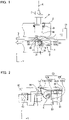
- Fig. 1 illustrates a first embodiment of a cutting die D according to the present invention.
- Fig. 1 describes a tool including the cutting die D and a cutting punch P in collaboration with that.
- the tool in Fig. 1 is applied to a turret punch press ( Figs. 17(A) and 17(B) ), for example, and a ram striker 2 is mounted on an upper frame 1, the cutting punch P is mounted on an upper turret 6, the cutting die D according to the present invention in collaboration with the cutting punch P is mounted on a lower turret 7, respectively.
- a through hole 40 is formed, and the cutting punch P is supported by an upper edge of the through hole 40 through a lift spring 31.
- the cutting die D according to the present invention is fixed.
- the cutting die D has a columnar trapezoidal shape as a whole as is well-known (corresponding to Fig. 4 ), in which a cutting chip 50 is incorporated, an ejector plate 60 covering a die body 41 including the cutting chip 50 is provided, and the ejector plate 60 is urged by a spring 43 ( Fig. 1 ) and communicates with a scrap discharge hole 39.
- the cutting chip 50 is used in cutting works in general by placing a work W thereon and moving it, and when seen from a front (corresponding to Fig. 5 ), it has a diamond shape, for example, with bite-shaped blade edges 50A, 50B, 50C, and 50D formed at tip ends thereof, and is mounted on a chip holder 36 through a bolt 37.
- the ejector plate 60 constitutes a simple vertically moving unit instead of an original vertical moving mechanism ( Figs. 6 and 7 ).
- the cutting die D ( Fig. 1 ) according to the present invention usually has the vertically moving mechanism such as a cylinder provided below that and by lowering when the work W is moved, the cutting chip 50 leaves the work W so as not to scratch a back surface thereof, and by rising when the work W is machined, the work W is cut by the cutting chip 50, but the ejector plate 60 constitutes a simple vertically moving unit which will be described later ( Figs. 6 and 7 ) instead of such original vertically moving mechanism.
- the vertically moving mechanism such as a cylinder provided below that and by lowering when the work W is moved, the cutting chip 50 leaves the work W so as not to scratch a back surface thereof, and by rising when the work W is machined, the work W is cut by the cutting chip 50, but the ejector plate 60 constitutes a simple vertically moving unit which will be described later ( Figs. 6 and 7 ) instead of such original vertically moving mechanism.
- a resistance member 51 fixed to a side wall 39A of the scrap discharge hole 39 formed in the die body 41 and penetrating through the ejector plate 60 is provided.
- the resistance member 51 is constituted by a vertical portion 51B extending vertically downward along the side wall 39A of the scrap discharge hole 39 and an inclined portion 51A penetrating through the ejector plate 60 continuously to the vertical portion 51B and extending diagonally upward to get close to a vicinity of an upper part of the cutting chip 50.
- the work W is lowered together with the ejector plate 60 and is moved in contact with the cutting chip 50 while cutting work such as V-groove machining is performed and thus, the swarf K generated at that time is guided so as to pass through the opening portion 152 between the cutting chip 50 and the resistance member 51 and collides against the resistance member 51, is given resistance, is finely divided and is discharged through the scrap discharge hole 39 to the outside.
- the cutting die which finely divides the swarf generated during cutting of the work so as to prevent clogging by scrap is provided, and since the clogging by scrap does not occur any more, the swarf K does not scratch the back surface of the work W any more, whereby the value of the work W as a product is maintained, and machining is continued.
- the first embodiment described above is particularly effective when there is a concern that a long and curled swarf K is generated and remains in the scrap discharge hole 39, which causes clogging by scrap as illustrated in Fig. 18(A) .
- a shape of the entire cutting die D, a shape of the cutting chip 50, a function of the ejector plate 60 and the like are all common in the first to sixth embodiments.
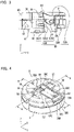
- Fig. 2 illustrates a second embodiment of the cutting die D according to the present invention.
- Fig. 2 the cutting punch P which is the other tool, the work W, a clamp 13 gripping it and the like are omitted but only the cutting die D is described, and the same also applies to Fig. 3 .
- the resistance member 53 is constituted by a horizontal inclined portion 53A and an L-shaped portion 53B fixed to the die body 41 by the same fixing unit, and the L-shaped portion 53B enters into the scrap discharge hole 39.
- the horizontal inclined portion 53A is constituted by a horizontal part 53A2 tightened by a bolt, for example, which is a fixing unit 61 and arranged horizontally and an inclined part 53A1 continuing to the horizontal part 53A2 and extending diagonally upward so as to get close to the vicinity of the upper part of the cutting chip 50.
- the L-shaped portion 53B is constituted by a horizontal part 53B1 tightened by a bolt which is the fixing unit 61 and arranged horizontally and a vertical part 53B2 continuing to the horizontal part 53B1, inclined downward at a right angle and entering into the scrap discharge hole 39.
- the swarf K generated at that time passes through the opening portion 152 between the cutting chip 50 and the resistance member 53 and is guided and collides against the resistance member 53, is given resistance and is finely divided and is discharged through the scrap discharge hole 39 to the outside.
- the resistance member 53 illustrated in Fig. 2 is particularly effective when there is a concern that the long and curled swarf K is generated and remains in the scrap discharge hole 39 and clogs it as illustrated in Fig. 18(A) similarly to Fig. 1 , and thus, the second embodiment in Fig. 2 can be regarded as a variation of the first embodiment in Fig. 1 .
- the long and curled swarf K may be stretched long downward, and in such a case, the swarf K cannot be divided even by the resistance member 53 in Fig. 2 .
- a resistance member 53 constituted by a guidance guard portion 53C fixed to a lower surface of the die body 41 and entering into the scrap discharge hole 39 is provided.
- the guidance guard portion 53C is constituted by a horizontal part 53C1 fixed to the lower surface of the die body 41 by a bolt 62, an upward inclined part 53C2 continuing to the horizontal part 53C1, inclined upward at larger than 90 degrees and entering into the scrap discharge hole 39 and in close contact with the chip holder 36 of the cutting chip 50, and a downward inclined part 53C3 continuing to the upward inclined part 53C2 and inclined downward at larger than 90 degrees in an opposite direction in the scrap discharge hole 39.
- the swarf K when the swarf K is generated due to cutting by the cutting chip 50, the swarf K passes through the opening portion 152 between the cutting chip 50 and the resistance member 53 and then hits the downward inclined part 53C3 of the guidance guard portion 53C and changes its course to the right, collides against the horizontal inclined portion 53A and the L-shaped portion 53B originally provided and is given resistance, is finely divided and is discharged through the scrap discharge hole 39 to the outside, whereby clogging by scrap is prevented.
- the resistance members 51 and 53 in the aforementioned first to third embodiments are both fixed to the die body 41 in the end, and in terms of the relation with the scrap discharge hole 39, it is provided around the scrap discharge hole 39 and thus, according to the present invention, the swarf K generated from the work W is divided through the resistance members 51 and 53 and is discharged to the outside without remaining in the scrap discharge hole 39 and thus, the effect of preventing clogging by scrap is exerted.
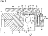
- Figs. 4 to 9 are views illustrating a fourth embodiment of the present invention.
- the cutting die D has a columnar trapezoidal shape ( Fig. 4 ) as a whole as is well-known, the cutting chip 50 is incorporated, the ejector plate 60 covering the die body 41 including the cutting chip 50 is provided, and a resistance member 55 is fixed to the die body 41.
- the cutting chip 50 is used in cutting work in general similarly by placing a work W thereon and moving it, and when seen from a front as illustrated in Fig. 5 , it has a diamond shape, for example, with the bite-shaped blade edges 50A, 50B, 50C, and 50D formed at the tip ends thereof , and is mounted on the chip holder 36 through the bolt 37.
- the chip holder 36 of the cutting chip 50 supports the resistance member 55.
- both side plates 36A and 36B extend to a rear from a head portion 36C on a front to which the cutting chip 50 is fixed, and a base 36D is provided on lower parts in the rear of the both side plates 36A and 36B.
- the resistance member 55 of the fourth embodiment has a cuboid shape as a whole, in which a front surface 55B has the opening portion 52 which faces the cutting chip 50 and the head portion 36C having the chip holder 36 fixed thereto and through which the swarf K passes.
- both side surfaces 55D and 55E of the resistance member 55 face the both side plates 36A and 36B of the chip holder 36, and an upper surface 55A and a rear surface 55C are exposed from the chip holder 36.
- the resistance member 55 is fixed to the die body 41 through the base 36D of the chip holder 36 by inserting a fixing unit 63 from the upper surface 55A in the vicinity of the rear surface 55C. That is, a rear portion 55F ( Fig. 8 ) of the resistance member 55 is fixed to the die body 41 through the base 36D of the chip holder 36.
- a division chamber 70 is formed, and the division chamber 70 is constituted by a first chamber 71 communicating with the opening portion 52 and a second chamber 72 which communicates with the first chamber 71, is located at a position lower than that and a scrap discharge hole 39 side ( Fig. 7 ) of which is opened.
- the swarf K having passed through the opening portion 52 is guided to the resistance member 55 and then, is given resistance by the first chamber 71 and the second chamber 72 or the first chamber 71 or the second chamber 72 and is divided and is discharged through the scrap discharge hole 39 to the outside, whereby clogging by scrap is prevented.
- the first chamber 71 is opened at the cutting chip 50 side and at the lower side and is closed at the rear side, and has a ceiling wall 71B having a triangular section communicating with the opening portion 52.
- the closed rear wall 71A ( Figs. 7 and 8 ) has a shape of a half of a triangular pyramid as a whole for convenience of the tool.
- a shape of the ceiling wall 71B of the first chamber 71 is constituted having a triangular section due to the following reason.
- the ceiling wall 71B having a triangular section guides the swarf K having passed through the opening portion 52 smoothly along the ceiling wall 71B, the swarf K is given resistance and divided by the rear wall 71A, a horizontal wall 72B constituting the second chamber 72 which will be described later, and a side wall 72A having a horseshoe shape as a whole and is carried out through the scrap discharge hole 39 to the outside, whereby clogging by scrap is prevented.
- the shape of the ceiling wall 71B communicating with the opening portion 52 is a triangular section.
- the second chamber 72 located at a position lower than the first chamber is opened at the cutting chip 50 side and at the scrap discharge hole 39 side and communicates with the first chamber 71 through the opened lower part, and has the horizontal wall 72B provided continuing to the first chamber 71 and the side wall 72A orthogonal to the horizontal wall 72B and having a horseshoe shape as a whole.
- the ejector plate 60 constitutes a simple vertically moving unit instead of the original vertically moving mechanism as described before ( Figs. 6 and 7 ). An entire operation of the fourth embodiment including the operation of this ejector plate 60 will be described below.
- rollers 57 and 58 are rotatably provided, and on the rollers 57 and 58, the work W ( Fig. 6 ) is placed.
- the swarf K generated by cutting of the work W passes through the opening portion 52 formed in the front surface 55B ( Figs. 4 , 7 and 8 ) of the resistance member 55 and is guided to the resistance member 55.
- the swarf K is given resistance and is finely divided by the rear wall 71A constituting the first chamber 71 of the division chamber 70, the horizontal wall 72B constituting the second chamber 72, and the side wall 72A having a horseshoe shape as a whole as described above, and is discharged through the scrap discharge hole 39 to the outside.
- the swarf K having passed through the opening portion 52 which is a part of the open portion 152, that is, the open portion 152(52) ( Fig. 7 ) is guided to the resistance member 55 and then, is given resistance and is divided by the first chamber 71 and the second chamber 72 or the first chamber 71 or the second chamber 72 and is discharged through the scrap discharge hole 39 to the outside, whereby clogging by scrap is prevented.
- the present invention similarly has an effect of providing a cutting die which finely divides the swarf generated when the work is cut so as to prevent clogging by scrap, and since clogging by scrap does not occur any more, the back surface of the work W is not scratched by the swarf K, the value of the work W as a product is maintained, and the machining is continued.
- the fourth embodiment described above is particularly effective when there is a concern that, as illustrated in Fig. 18(C) , continuous long swarf K generated as the result of machining of the long V-groove remains in the scrap discharge hole 39 and causes clogging by scrap.
- Figs. 10 to 16(A) and 16(B) are views illustrating a fifth embodiment of the present invention.
- the cutting die D has a columnar trapezoidal shape ( Fig. 10 ) as a whole as is well-known, the cutting chip 50 is incorporated, the ejector plate 60 covering the die body 41 including the cutting chip 50 is provided, and a resistance member 56 is fixed to the ejector plate 60.
- a point that the resistance member 56 ( Fig. 10 ) is fixed not to the die body 41 but to the ejector plate 60 is a marked difference from the first to fourth embodiments.
- the gap between the back surface of the work W and the resistance member 56 is not varied, and by setting the gap to a predetermined value in advance, the swarf K does not remain in the gap or clogging by scrap does not occur.
- the work W, the ejector plate 60, and the resistance member 56 are vertically moved integrally on the basis of a pressing force of the cutting punch P ( Fig. 1 ) and thus, the gap between the back surface of the work W ( Fig. 10 ) and the resistance member 56 is not changed by the type of the machining, that is, whether it is the shallow V-groove machining or deep V-groove machining, for example.
- a difference between the first to fourth embodiments and the fifth embodiment is presence of a space portion at a position on the die body 41 and corresponding to the rollers 57 and 58 of the ejector plate 60.
- the cutting chip 50 is similarly used for cutting in general by placing the work W thereon and moving it, and as illustrated in Fig. 11 , it has a diamond shape, for example, when seen from the front, with bite-shaped blade edges 50A, 50B, 50C, and 50D formed at tip ends thereof, and is mounted on the chip holder 36 through the bolt 37.
- the resistance member 56 is fixed to the ejector plate 60 ( Fig. 10 ).
- This resistance member 56 of the fifth embodiment ( Figs. 10 and 15 ) has an elongated opening portion 52 which is opened at the front and from which the cutting chip 50 ( Fig. 10 ) is exposed, and the swarf K ( Fig. 13 ) generated from the work W passes through this opening portion 52 and is guided to the resistance member 56.
- the entire outer side surface 59 of the resistance member 56 faces the rollers 57 ( Fig. 10 ) on the ejector plate 60 side and 58 and an entire inner side surface 69, and an upper surface 56A and a rear surface 56C are exposed from the ejector plate 60.
- the resistance member 56 ( Fig. 10 ) has a fixing unit 64 such as a bolt, for example, inserted from the upper surface 56A in the vicinity of the rear surface 56C, and a rear portion 56F of the resistance member 56 is fixed to the ejector plate 60 through a stepped portion 60D of the ejector plate 60 ( Fig. 15 ).
- a fixing unit 64 such as a bolt, for example, inserted from the upper surface 56A in the vicinity of the rear surface 56C, and a rear portion 56F of the resistance member 56 is fixed to the ejector plate 60 through a stepped portion 60D of the ejector plate 60 ( Fig. 15 ).
- the ejector plate 60 to which the resistance member 56 is fixed is mounted on the die body 41 on which the space portions 45 and 46 described above are formed through the spring 43 and a stopper 44 (in this case, positions of numbers 0 and 90 described on the ejector plate 60 ( Fig. 15 ) are assumed to be positioned at positions of keyways 41A and 41B to the lower turret 7 ( Fig. 1 ) of the die body 41, respectively, so that the angle position of the cutting die D according to the present invention in the turret punch press ( Fig. 17 ) is known.
- the work W, the ejector plate 60, and the resistance member 56 are vertically moved integrally so that the gap between the back surface of the work W and the resistance member 56 is not varied depending on the type of working and the clogging by the swarf K in the gap does not cause clogging by scrap.
- a division chamber 80 is formed, and the division chamber 80 is constituted by a first chamber 81 communicating with the opening portion 52 and a second chamber 82 which communicates with the first chamber 81 and is located at a position lower than that and the scrap discharge hole 39 side ( Fig. 13 ) of which is opened.
- the swarf K having passed through the opening portion 52 ( Fig.13 ) which is a part of the open portion 152, that is, the open portion 152(52) between the cutting chip 50 and the resistance member 56 is guided to the resistance member 56 and then, is given resistance by the first chamber 81 and the second chamber 82 or the first chamber 81 or the second chamber 72 and is divided and is discharged through the scrap discharge hole 39 to the outside, whereby clogging by scrap is prevented.
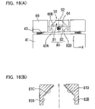
- the first chamber 81 is opened at the opening portion 52 side on an upper side, at the front side (right side in Fig. 15 ), and at a lower side, and has a horizontal ceiling wall 81A at the same height position as the opening portion 52 and an inclined wall 81B having a U-shape in entirety gradually opening downward continuing to the horizontal ceiling wall 81A and the opening portion 52.
- the resistance member 56 is fixed to the ejector plate 60, and when the ejector plate 60 is vertically moved, the resistance member 56 is also vertically moved at the same time, and thus the relief portions 81C ( Fig. 15 ) and 81D are provided to avoid interference between the resistance member 56 and the cutting chip 50.
- the second chamber 82 located at the position lower than the first chamber 81 is opened at a front side (right side in Fig. 15 ), at a rear side (left side in Fig. 15 ), and at a lower side, that is, the scrap discharge hole 39 side ( Fig. 13 ) and communicates with the first chamber 81 ( Figs. 15 and 16(A) ) through the opened lower side.
- the second chamber 82 has vertical walls 82A and 82B provided along a longitudinal direction (Y-axis direction) of linear portions on both sides at a lowermost end of the inclined wall 81B having a U-shape in entirety constituting the first chamber 81.
- the ejector plate 60 similarly constitutes a simple vertically moving unit instead of the original vertically moving mechanism ( Figs. 12 to 14 ).
- the ejector plate 60 is, as is well-known, urged upward to the die body 41 ( Fig. 14 ) through the spring 43 and the stopper 44 (common also to the first to fourth embodiments), and an operation of the entire fifth embodiment will be described including the operation of this ejector plate 60.
- a point that the resistance member 56 is fixed to this ejector plate 60 is different from the first to fourth embodiments.
- the rollers 57 and 58 are rotatably provided, and the work W ( Fig. 12 ) is placed on the rollers 57 and 58.
- the cutting punch P ( Fig. 1 ) is at an upper limit position, for example, the work W ( Fig. 12 ) is not pressed but is moved along the path line PL, while the ejector plate 60 is urged upward through the spring 43 ( Fig. 14 ) and the stopper 44, and the cutting chip 50 is not brought into contact with the work W and its back surface is not scratched.
- the swarf K generated by cutting of the work W passes through the opening portion 52 ( Figs. 10 , 13 , and 15 ) formed in the front of the resistance member 56 and is guided to the resistance member 56.
- the swarf K is given resistance and is finely divided by the horizontal ceiling wall 81A constituting the first chamber 81 of the division chamber 80, the inclined wall 81B having the U-shape entirety, and the vertical walls 82A and 82B constituting the second chamber 82, and is discharged through the scrap discharge hole 39 to the outside.
- the swarf K having passed through the opening portion 52 is guided to the resistance member 56, is then given resistance and divided by the first chamber 81 and the second chamber 82 or the first chamber 81 or the second chamber 82 and is discharged through the scrap discharge hole 39 to the outside, whereby clogging by scrap is prevented.
- the present invention similarly has an effect of providing a cutting die which finely divides the swarf generated during cutting of the work so as to prevent clogging by scrap, and since clogging by scrap does not occur any more, the back surface of the work W is not scratched by the swarf K, the value of the work W as a product is maintained, and the machining is continued.
- the fifth embodiment described above is particularly effective similarly when there is a concern that, as illustrated in Fig. 18(C) , continuous long swarf K generated as the result of machining of the long V-groove remains in the scrap discharge hole 39 and causes clogging by scrap.
- the space portions 45 and 46 communicating with the scrap discharge hole 39 are formed ( Figs. 11 and 15 ) and thus, even if the swarf K generated during working of the work W adheres to the rollers 57 and 58 of the ejector plate 60, the adhering swarf K is discharged from the scrap discharge hole 39 through the space portions 45 and 46 to the outside, and clogging by scrap does not occur.
- the relief portions 81C ( Fig. 15 ) and 81D to the blade edges 50D ( Fig. 11 ) and 50A of the cutting chip 50 are provided ( Fig. 16(B) ) and thus, interference between the resistance member 56 vertically moving with the ejector plate 60 and the cutting chip 50 is avoided.
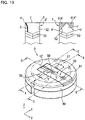
- Figs. 19 to 25 are views illustrating a sixth embodiment of the present invention.
- the cutting die D has a columnar trapezoidal shape as a whole as is well-known ( Fig. 19 ), the cutting chip 50 is incorporated, the ejector plate 60 covering the die body 41 including the cutting chip 50 is provided, and a resistance member 59 is fixed to the ejector plate 60.
- a difference between the sixth embodiment and the first to fourth embodiments is similar to that between the fifth embodiment and them, and the cutting chip 50 ( Fig. 20 ) is totally the same as that of the fifth embodiment (paragraph numbers 0071 to 0080) and moreover, a correspondence relation between the resistance member 59 ( Fig. 19 ) and the ejector plate 60, the fixing unit to the ejector plate 60, a relation between the ejector plate 60 and the die body 41, an effect of fixing the resistance member 59 to the ejector plate 60 (paragraph numbers 0083 to 0086), and the interference avoiding unit between the resistance member 59 and the cutting chip 50 are similar to those of the fifth embodiment (paragraph numbers 0090 to 0091), and detailed description will be omitted.
- the resistance member 59 is fixed to the ejector plate 60 similarly to the fifth embodiment ( Fig. 19 ), and the resistance member 59 will be described below in detail.
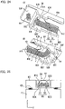
- the resistance member 59 ( Figs. 19 and 24 ) of this sixth embodiment has the elongated opening portion 52 which is opened at a front side (right side of Fig. 24 (A), for example) and from which the cutting chip 50 ( Fig. 19 ) is exposed, and the swarf K ( Fig. 22 ) generated from the work W passes through this opening portion 52 and is guided to the resistance member 59.
- a difference of the opening portion 52 between the sixth embodiment ( Fig. 19 ) and the fifth embodiment ( Fig. 10 ) is as follows.
- the opening portions 52 of the sixth embodiment ( Fig. 19 ) and the fifth embodiment ( Fig. 10 ) facing the cutting chip 50 has a triangle T (right in an upper view in Figs. 19 and 24 (B)) with a tapered shape for the former and a square F ( Fig. 10 and left in an upper view in Fig. 19 ) with a tip-expanded shape for the latter.
- the shape of the rear (the side facing the cutting chip 50) of the opening portion 52 is changed as described above because there is a difference in a clogging degree by the swarf depending on the cutting method.
- a desired V-groove V3 is formed in some cases.
- the swarf generated in this case tries to pass through the opening portion 52 not through the center of the cutting chip 50 but in a state biased to the right side ( Figs. 10 and 19 ) or the left side.
- the rear side (the side facing the cutting chip 50) of the opening portion 52 is formed by the square F made of a, b, and c as in the fifth embodiment ( Fig. 10 ), the following disadvantage occurs.
- the swarf K generated by cutting of the work W with the cutting chip 50 passes through the opening portion 52 not through the center of the cutting chip 50 but in the state biased to the right side or to the left side.
- the swarf K having passed through is divided while being curled upward in some cases.
- An action to pop out upward works in the divided swarf K, which is caught between the a portion ( Fig. 10 and left in the upper view in Fig. 19 ) or the b portion and the cutting chip 50 and is not smoothly guided into the resistance member 56 in some cases ( Fig. 13 ).
- the swarf K generated by cutting of the work W with the cutting chip 50 is not caught between the opening portion 52 and the chip 50 but is smoothly guided into the resistance member 59 ( Fig. 22 ).
- the triangle T which is the shape of the rear of the opening portion 52 includes an isosceles triangle, for example.
- a semi-circular, semi-oval or trapezoidal shape exerts the similar effect as long as it is tapered.
- the tapered opening portion shape can be applied also to the fourth embodiment ( Fig. 4 ) and the fifth embodiment ( Fig. 10 ).
- a division chamber 90 is similarly formed, and the division chamber 90 is constituted by a first chamber 91 communicating with the opening portion 52 and a second chamber 92 which communicates with the first chamber 91 and is located at a position lower than that and the scrap discharge hole 39 side ( Fig. 22 ) of which is opened.
- the first chamber 91 ( Fig. 24 ) similarly has the horizontal ceiling wall 91A at the same height position as the opening portion 52 and an inclined wall 91B having a U-shape in entirety gradually opening downward continuing to the horizontal ceiling wall 91A and the opening portion 52.
- Steps 91C are continuously provided from top to bottom over the inclined wall 91B having a U-shape in entirety.
- the swarf K ( Fig. 22 ) having passed through the opening portion 52 which is a part of the open portion 152, that is, the open portion 152(52) between the cutting chip 50 and the resistance member 59 and guided to the resistance member 59 is given stronger resistance and is further finely divided by a corner part of the steps 91C provided on the inclined wall 91B constituting the first chamber 91 of the division chamber 90 and is discharged from the scrap discharge hole 39 to the outside.
- the swarf K ( Fig. 13 ) is given resistance by the simply flat inclined wall 81B ( Figs. 13 and 15 ) on which the steps 91C ( Fig. 22 ) as in the sixth embodiment are not provided, but the resistance is relatively small.
- the second chamber 92 ( Fig. 24 ) constituting the division chamber 90 in the sixth embodiment similarly has vertical walls 92A and 92B.
- the vertical walls 92A and 92B constitute the aforementioned first chamber 91 and moreover, they are provided along the longitudinal direction (Y-axis direction) of the linear portion on both sides of the lowermost end of the entirely U-shaped inclined wall 91B on which the steps 91C are provided.
- an entry preventing wall 92C ( Fig. 24 ) connecting the both vertical walls 92A and 92B is provided on a rear portion 59F side of the resistance member 59, that is, the side fixed to the ejector plate 60 ( Fig. 19 ) by insertion of the bolt 64 or the like.
- the swarf K divided by the first chamber 91 and the second chamber 92 constituting the division chamber 90 ( Figs. 22 and 24 ) of the sixth embodiment is inhibited by this entry preventing wall 92C and does not enter the gap formed between the vertically moving ejector plate 60 and the die body 41 and the vertically moving operation ( Fig. 23 ) of the ejector plate 60 is performed extremely smoothly.
- the swarf K enters the gap between the ejector plate 60 and the die body 41 and prevents a smooth vertically moving operation of the ejector plate 60 in some cases.
- the both vertical walls 92A and 92B( Fig. 24 ) constituting the second chamber 92 of the division chamber 90 become deeper as they get closer to the side fixed to the ejector plate 60 which is the rear portion 59F side of the resistance member 59 (92A', 92B').
- the entry preventing wall 92C connecting the deeper portions 92A' and 92B' (Figs. 24(A) and 24(B)) is provided on the rear portion 59F side of the resistance member 59.
- an entirely U-shaped chamber 92D ( Figs. 22 and 24 ) surrounded by the aforementioned deeper portions 92A' and 92B' and the entry preventing wall 92C connecting the both portions 92A' and 92B' is fully contained in the scrap discharge hole 39 and moreover, completely covers the gap between the ejector plate 60 and the die body 41.
- the swarf K generated from the work W ( Fig. 22 ) during working is prevented by the U-shaped chamber 29D and does not enter the gap between the ejector plate 60 and the die body 41 as described above.
- entry preventing wall 92C ( Fig. 24 ) can be also applied to the fifth embodiment ( Fig. 10 ) .
- the work W gripped by the clamp 13 ( Fig. 17 ) constituting a work positioning device is positioned at a working position K1 ( Fig. 17(B) ), and it is moved in an arrow direction with the work W placed on the rollers 57 ( Fig. 21 ) and 58.
- the cutting punch P ( Fig. 1 ) when the work W is moved ( Fig. 21 ), the cutting punch P ( Fig. 1 ) is at the upper limit position, for example, the work W ( Fig. 21 ) is not pressed but is moved along the path line PL, while the ejector plate 60 is similarly urged upward ( Fig. 23 ), but when the work W is machined ( Fig. 22 ), the cutting punch P ( Fig. 1 ) lowers and presses the work W and thus, the work W lowers together with the ejector plate 60 ( Fig. 22 ) and as illustrated, moves in contact with the cutting chip 50 and performs cutting such as V-groove machining, and the generated swarf K passes through the opening portion 52 and is guided and divided by the resistance member 59.
- the generated swarf K tries to pass through the opening portion 52 in the state biased to the right end ( Fig. 19 ) or the left side of the cutting chip 50.
- the swarf K guided into the resistance member 59 ( Fig. 22 ) is given strong resistance by the steps 91C provided in the first chamber 91 constituting the division chamber 90 and thus, it is further finely divided, whereby clogging by scrap is prevented.
- the further finely divided swarf K ( Fig. 22 ) tries to enter the gap between the ejector plate 60 and the die body 41, but since the entry preventing wall 92C connecting the both vertical walls 92A and 92B of the second chamber 92 constituting the division chamber 90 is provided, the entry is prevented, and the smooth vertically moving operation of the ejector plate 60 is guaranteed.
- Fig. 17 is a view illustrating a turret punch press in the punch press to which the present invention is applied, and the turret punch press has the upper turret 6 and the lower turret 7 as described above ( Fig. 1 ).
- a tool including the cutting die D ( Figs. 1 to 16 ) according to the present invention and the cutting punch P collaborating with it and tools including various punches P and dies D for punching, molding, and the like are concentrically arranged, respectively.
- Chains 4 and 5 are wound around a rotating shaft 8 of the upper turret 6 ( Fig. 17(B) ) and a rotating shaft 9 of the lower turret 7, respectively, and the chains 4 and 5 are wound around a driving shaft 3, while, immediately above the punch P at the working position K1 and on the upper frame 1, as described above ( Fig. 1 ), the ram striker 2 for pressing the cutting punch P and pushing down the entire punch P is provided, for example.
- a length of the generated swarf K ( Fig. 18 ), a degree of curling and the like are different, and a degree of difficulty of clogging by scrap is made different in accordance with that and thus, the optimal cutting die D according to the present invention to be used and the cutting punch P collaborating with that can be selected from among Figs. 1 to 4 and Fig. 10 , for example.
- a Y-axis LM guide rail 17 is laid on a lower frame 21 ( Fig. 17(B) ) of the turret punch press, a support bracket 16 is slidingly connected to the Y-axis LM guide rail 17, a carriage base 11 is placed on the support bracket 16, a ball screw 14 of a Y-axis motor My provided on the upper frame 1 is screwed with the carriage base 11, a carriage 12 on which the clamp 13 is mounted is slidingly connected to an X-axis LM guide rail (not shown) on the carriage base 11, and a ball screw 15 of an X-axis motor Mx ( Fig. 17(A) ) is screwed with the carriage 12.
- a center table 10 is fixed, side tables 10A and 10B are arranged on both sides of the fixing table 10, and the side tables 10A and 10B are mounted on the support bracket 16.
- the carriage 12 is moved in the X-axis direction on the carriage base 11 by rotation of the X-axis motor Mx, while the carriage base 11 supported by the support bracket 16 is moved in the Y-axis direction together with the side tables 10A and 10B by rotation of the Y-axis motor My (Fig. 10(A)).
- the work W gripped by the clamp 13 ( Fig. 1 ) mounted on the carriage 12 ( Fig. 17 ) is positioned at the working position K1, and the work W is moved on the cutting chip 50 as it is, whereby the cutting such as V-groove machining can be performed by the cutting die D according to the present invention.
- a relation between the swarf K ( Figs. 1 to 3 , Figs, 7 , 13 , and 22 ) generated by the cutting and the resistance members 51, 53, 55, 56, and 59 constituting the present invention is constant, and the swarf K passes through the opening portion 52 on the front and is guided and collides against the resistance member 51, 53, 55, 56 or 59, is given resistance, finely divided and discharged from the scrap discharge hole 39 to the outside.
- the present invention is used in the cutting die which finely divides the swarf generated during cutting of the work and prevents clogging by scrap and moreover, it is applied not only to a single punch press in which a pair of tools is arranged but also to a turret punch press having an upper turret and a lower turret in which a plurality of pairs of tools is arranged, which is extremely useful.
Landscapes
- Engineering & Computer Science (AREA)
- Mechanical Engineering (AREA)
- Physics & Mathematics (AREA)
- Optics & Photonics (AREA)
- Punching Or Piercing (AREA)
- Auxiliary Devices For Machine Tools (AREA)
- Perforating, Stamping-Out Or Severing By Means Other Than Cutting (AREA)
- Cutting Tools, Boring Holders, And Turrets (AREA)
Claims (8)
- Matrice de coupe (D) comportant une plaquette de coupe (50) appliquée à une presse de poinçonnage et découpant une pièce (W) en collaboration avec un poinçon de coupe (P),
caractérisée en ce qu'un élément de résistance (51, 53, 55, 56, 59) pour guider le copeau (K) généré durant la découpe de la pièce (W) à travers la plaquette de coupe (50) et le diviser en lui opposant une résistance est pourvu autour d'un trou d'évacuation des déchets (39) de telle sorte que le copeau divisé (K) ne reste pas dans le trou d'évacuation des déchets (39) mais est éliminé vers l'extérieur de manière à éviter une obstruction par des déchets, et l'élément de résistance (51, 53, 55, 56, 59) est fixé à une paroi latérale du trou d'évacuation des déchets (39) formé dans le corps de matrice (41) et traverse une plaque d'éjecteur (60). - Matrice de coupe (D) selon la revendication 1, dans laquelle
l'élément de résistance (51, 53, 55, 56, 59) est constitué par une portion verticale qui s'étend verticalement vers le bas le long de la paroi latérale du trou d'évacuation des déchets (39) et une portion inclinée qui traverse la plaque d'éjecteur (60) de manière continue jusqu'à la portion verticale et qui s'étend en diagonale vers le haut de manière à s'approcher d'une partie supérieure de la plaquette de coupe (50). - Matrice de coupe (D) selon la revendication 1, dans laquelle
l'élément de résistance (51, 53, 55, 56, 59) est constitué par une portion inclinée horizontale et une portion en forme de L fixées au corps de matrice (41) par la même unité de fixation (61, 62, 63, 64), et la portion en forme de L entre dans le trou d'évacuation des déchets (39) . - Matrice de coupe (D) selon la revendication 3, dans laquelle
la portion inclinée horizontale est constituée par une partie horizontale serrée par l'unité de fixation (61, 62, 63, 64) et agencée horizontalement et une partie inclinée qui continue jusqu'à la partie horizontale et s'étend en diagonale vers le haut de manière à s'approcher de la partie supérieure de la plaquette de coupe (50), et la portion en forme de L est constituée par une partie horizontale serrée par l'unité de fixation (61, 62, 63, 64) et agencée horizontalement et une partie verticale qui continue jusqu'à la partie horizontale, inclinée vers le bas à angle droit et entrant dans le trou d'évacuation des déchets (39). - Matrice de coupe (D) selon la revendication 3, dans laquelle
l'élément de résistance (51, 53, 55, 56, 59) est constitué par une portion protectrice de guidage fixée à une surface inférieure du corps de matrice (41) et entrant dans le trou d'évacuation des déchets (39), en plus de la portion inclinée horizontale et de la portion en forme de L fixées au corps de matrice (41) par la même unité de fixation (61, 62, 63, 64). - Matrice de coupe (D) selon la revendication 5, dans laquelle
la portion protectrice de guidage est constituée par une partie horizontale fixée à la surface inférieure du corps de matrice (41), une partie inclinée vers le haut qui continue jusqu'à la partie horizontale, inclinée vers le haut sur plus de 90 degrés, entrant dans le trou d'évacuation des déchets (39) et en contact étroit avec un support de plaquette (36) de la plaquette de coupe (50), et une partie inclinée vers le bas qui continue jusqu'à la partie inclinée vers le haut et inclinée vers le bas sur plus de 90 degrés en direction opposée dans le trou d'évacuation des déchets (39). - Matrice de coupe (D) comportant une plaquette de coupe (50) appliquée à une presse de poinçonnage et découpant une pièce (W) en collaboration avec un poinçon de coupe (P),
caractérisée en ce qu'un élément de résistance (51, 53, 55, 56, 59) comportant une portion d'ouverture (52) à travers laquelle passe le copeau (K) généré durant la coupe d'une pièce (W) à travers une plaquette de coupe (50) et divisant le copeau (K) en exerçant une résistance sur le copeau (K) est pourvu autour d'un trou d'évacuation des déchets (39) de telle sorte que le copeau divisé (K) ne reste pas dans le trou d'évacuation des déchets (39) mais est éliminé vers l'extérieur de manière à éviter une obstruction par les copeaux (K). - Matrice de coupe selon la revendication 7, dans laquelle
une forme conique est conformée à l'arrière de la portion d'ouverture de l'élément de résistance.
Applications Claiming Priority (3)
| Application Number | Priority Date | Filing Date | Title |
|---|---|---|---|
| JP2014075912 | 2014-04-02 | ||
| JP2015044670A JP5873197B2 (ja) | 2014-04-02 | 2015-03-06 | 切削加工用ダイ |
| PCT/JP2015/058204 WO2015151829A1 (fr) | 2014-04-02 | 2015-03-19 | Outil de découpage |
Publications (3)
| Publication Number | Publication Date |
|---|---|
| EP3127628A1 EP3127628A1 (fr) | 2017-02-08 |
| EP3127628A4 EP3127628A4 (fr) | 2018-01-03 |
| EP3127628B1 true EP3127628B1 (fr) | 2022-06-08 |
Family
ID=54240160
Family Applications (1)
| Application Number | Title | Priority Date | Filing Date |
|---|---|---|---|
| EP15772332.1A Active EP3127628B1 (fr) | 2014-04-02 | 2015-03-19 | Outil de découpage |
Country Status (7)
| Country | Link |
|---|---|
| US (1) | US10010924B2 (fr) |
| EP (1) | EP3127628B1 (fr) |
| JP (1) | JP5873197B2 (fr) |
| KR (1) | KR101758861B1 (fr) |
| CN (1) | CN106794510B (fr) |
| TW (1) | TWI610731B (fr) |
| WO (1) | WO2015151829A1 (fr) |
Families Citing this family (8)
| Publication number | Priority date | Publication date | Assignee | Title |
|---|---|---|---|---|
| DE102017118268A1 (de) | 2017-08-10 | 2019-02-14 | Trumpf Werkzeugmaschinen Gmbh + Co. Kg | Werkzeug und Verfahren zum Bearbeiten von plattenförmigen Werkstücken, insbesondere Blechen |
| JP2020124782A (ja) * | 2019-02-05 | 2020-08-20 | 日鉄めっき鋼管株式会社 | 溶接ビード除去装置及びそのビードカッタホルダ |
| DE102019211066B3 (de) * | 2019-07-25 | 2020-10-15 | Pass Stanztechnik Ag | Verfahren zum Schneiden einer nutförmigen Ausnehmung in ein Werkstück |
| US12303960B2 (en) * | 2020-05-28 | 2025-05-20 | Zhejiang Sanhua Automotive Components Co., Ltd. | Processing apparatus, control method for processing apparatus and heat exchanger |
| CN112246978B (zh) * | 2020-10-10 | 2022-06-28 | 南京瀚孚机械有限公司 | 一种稳定下料的冲压模具 |
| CN112873412B (zh) * | 2020-12-23 | 2022-06-28 | 广东天浩智能科技有限公司 | 一种电子产品加工用芯片冲切装置 |
| CN114536515B (zh) * | 2022-03-28 | 2023-07-21 | 北部湾大学 | 瓷板半成型一体装置 |
| US20250031382A1 (en) * | 2023-07-20 | 2025-01-23 | International Business Machines Corporation | Dielectric isolation for mram array |
Family Cites Families (16)
| Publication number | Priority date | Publication date | Assignee | Title |
|---|---|---|---|---|
| US4443143A (en) * | 1982-03-08 | 1984-04-17 | Kabushiki Kaisha Kobe Seiko Sho | Billet scalper and drive mechanism therefor |
| DE3438010C2 (de) | 1984-10-17 | 1986-08-28 | Ernst Peter 6638 Dillingen Braun | Brennbartentfernungsmaschine für Brammen, Blooms und Knüppel |
| GB2206513B (en) * | 1987-07-08 | 1991-11-06 | Amada Co Ltd | V-shaped groove forming machine and its control method |
| JP3297599B2 (ja) * | 1996-02-13 | 2002-07-02 | 株式会社アマダ | 連続切断金型 |
| US5823720A (en) * | 1996-02-16 | 1998-10-20 | Bitmoore | High precision cutting tools |
| JP2000233340A (ja) * | 1999-02-10 | 2000-08-29 | Toyota Motor Corp | 切粉除去装置 |
| DE29911152U1 (de) * | 1999-06-26 | 1999-11-04 | Mate Precision Tooling GmbH, 61440 Oberursel | Werkzeugvorrichtung zur spanenden Bearbeitung tafelförmiger Werkstücke |
| JP4471248B2 (ja) * | 2000-08-02 | 2010-06-02 | 株式会社アマダ | 金型装置 |
| US7479004B2 (en) * | 2002-06-18 | 2009-01-20 | Amada Company, Limited | Die and die device |
| ITMO20030208A1 (it) | 2003-07-22 | 2005-01-23 | Oto Mills Spa | Utensile scordonatore esterno con rompitruciolo. |
| TWM250746U (en) * | 2004-02-13 | 2004-11-21 | Leadwell Cnc Machines Mfg Corp | Multi-layer type scraping/brushing apparatus for cutting machine |
| TWM338739U (en) * | 2008-03-10 | 2008-08-21 | Sunco Pneumatic Tools Co Ltd | Chip and dust collection plate structure of plate cutting platform |
| JP2012061534A (ja) * | 2010-09-15 | 2012-03-29 | Murata Machinery Ltd | 切屑案内具付き工具および旋盤 |
| JP5940884B2 (ja) * | 2012-05-10 | 2016-06-29 | 株式会社アマダホールディングス | 切粉除去方法及び切削加工工具 |
| JP5944257B2 (ja) * | 2012-07-25 | 2016-07-05 | Dmg森精機株式会社 | 切屑吸引装置用工具ホルダ及び該工具ホルダを備えた工作機械 |
| EP3078432B1 (fr) * | 2015-04-08 | 2017-10-18 | TRUMPF Werkzeugmaschinen GmbH + Co. KG | Outil pour une machine d'usinage |
-
2015
- 2015-03-06 JP JP2015044670A patent/JP5873197B2/ja active Active
- 2015-03-19 US US15/300,080 patent/US10010924B2/en active Active
- 2015-03-19 WO PCT/JP2015/058204 patent/WO2015151829A1/fr not_active Ceased
- 2015-03-19 KR KR1020167030645A patent/KR101758861B1/ko active Active
- 2015-03-19 CN CN201580018582.9A patent/CN106794510B/zh active Active
- 2015-03-19 EP EP15772332.1A patent/EP3127628B1/fr active Active
- 2015-04-01 TW TW104110709A patent/TWI610731B/zh active
Also Published As
| Publication number | Publication date |
|---|---|
| JP5873197B2 (ja) | 2016-03-01 |
| JP2015199124A (ja) | 2015-11-12 |
| CN106794510A (zh) | 2017-05-31 |
| KR101758861B1 (ko) | 2017-07-17 |
| KR20160142859A (ko) | 2016-12-13 |
| CN106794510B (zh) | 2019-06-28 |
| EP3127628A1 (fr) | 2017-02-08 |
| US10010924B2 (en) | 2018-07-03 |
| US20170136518A1 (en) | 2017-05-18 |
| TWI610731B (zh) | 2018-01-11 |
| TW201600194A (zh) | 2016-01-01 |
| EP3127628A4 (fr) | 2018-01-03 |
| WO2015151829A1 (fr) | 2015-10-08 |
Similar Documents
| Publication | Publication Date | Title |
|---|---|---|
| EP3127628A1 (fr) | Outil de découpage | |
| JP6966955B2 (ja) | 切削加工方法、曲げ加工品の製造方法、被加工板材、加工処理用プログラム及び加工処理用プログラムの作成プログラム | |
| EP3960405B1 (fr) | Scie circulaire à table | |
| CA2692664A1 (fr) | Coupe-dechets interchangeable a ressort | |
| DE102016008607B4 (de) | Robotersystem, das mit einem Unterteilungselement versehen ist, das einen Teil einer Öffnung einer Abdeckung abdeckt | |
| US3935772A (en) | Punching device having selectable pinch point clearance | |
| US9908187B2 (en) | Tool and method for shear cutting a workpiece | |
| CN109482713A (zh) | 多特征连续成型冲裁机械 | |
| EP3388176B1 (fr) | Machine à scier circulaire capable de supprimer l'oscillation de la lame de scie circulaire | |
| JPH08206751A (ja) | 輪郭断面を持った材料の孔あけ加工機 | |
| CA2197417C (fr) | Outil a mortaiser | |
| CA2792162C (fr) | Appareil pourvu de zones de guidage de rebuts positionnees sur l' ensemble de coupe | |
| JP6353677B2 (ja) | セミホロー材のプレス剪断加工装置 | |
| JPH10314863A (ja) | プレス型のカム構造 | |
| DE10357923A1 (de) | Vorrichtung zum Umformen oder Zerteilen von Werkstücken mit integrierter Absaugeinrichtung | |
| JP2001025829A (ja) | プレス金型 | |
| KR101395300B1 (ko) | 피가공물의 홀 가공 공정이 단축되는 홀포밍 금형 어셈블리 | |
| KR20170112706A (ko) | 피어싱 금형의 피어싱 다이 | |
| CN222198701U (zh) | 一种冲床防护装置 | |
| CN220840302U (zh) | 一种亮饰条自动切断模 | |
| JPH07290173A (ja) | プレス用金型のノックアウト機構 | |
| KR100722556B1 (ko) | 프로그레시브 금형의 준비커팅장치 및 그 방법 | |
| CN222492393U (zh) | 模具钢加工定位装置 | |
| JP2859841B2 (ja) | パンチユニット | |
| JP2018176173A (ja) | 下型装置及びワークの折曲げ加工方法 |
Legal Events
| Date | Code | Title | Description |
|---|---|---|---|
| STAA | Information on the status of an ep patent application or granted ep patent |
Free format text: STATUS: THE INTERNATIONAL PUBLICATION HAS BEEN MADE |
|
| PUAI | Public reference made under article 153(3) epc to a published international application that has entered the european phase |
Free format text: ORIGINAL CODE: 0009012 |
|
| STAA | Information on the status of an ep patent application or granted ep patent |
Free format text: STATUS: REQUEST FOR EXAMINATION WAS MADE |
|
| 17P | Request for examination filed |
Effective date: 20161031 |
|
| AK | Designated contracting states |
Kind code of ref document: A1 Designated state(s): AL AT BE BG CH CY CZ DE DK EE ES FI FR GB GR HR HU IE IS IT LI LT LU LV MC MK MT NL NO PL PT RO RS SE SI SK SM TR |
|
| AX | Request for extension of the european patent |
Extension state: BA ME |
|
| DAV | Request for validation of the european patent (deleted) | ||
| DAX | Request for extension of the european patent (deleted) | ||
| A4 | Supplementary search report drawn up and despatched |
Effective date: 20171204 |
|
| RIC1 | Information provided on ipc code assigned before grant |
Ipc: B21D 28/34 20060101ALI20171128BHEP Ipc: B21D 28/14 20060101AFI20171128BHEP |
|
| STAA | Information on the status of an ep patent application or granted ep patent |
Free format text: STATUS: EXAMINATION IS IN PROGRESS |
|
| 17Q | First examination report despatched |
Effective date: 20210423 |
|
| GRAP | Despatch of communication of intention to grant a patent |
Free format text: ORIGINAL CODE: EPIDOSNIGR1 |
|
| STAA | Information on the status of an ep patent application or granted ep patent |
Free format text: STATUS: GRANT OF PATENT IS INTENDED |
|
| INTG | Intention to grant announced |
Effective date: 20220225 |
|
| GRAS | Grant fee paid |
Free format text: ORIGINAL CODE: EPIDOSNIGR3 |
|
| GRAA | (expected) grant |
Free format text: ORIGINAL CODE: 0009210 |
|
| STAA | Information on the status of an ep patent application or granted ep patent |
Free format text: STATUS: THE PATENT HAS BEEN GRANTED |
|
| AK | Designated contracting states |
Kind code of ref document: B1 Designated state(s): AL AT BE BG CH CY CZ DE DK EE ES FI FR GB GR HR HU IE IS IT LI LT LU LV MC MK MT NL NO PL PT RO RS SE SI SK SM TR |
|
| REG | Reference to a national code |
Ref country code: GB Ref legal event code: FG4D |
|
| REG | Reference to a national code |
Ref country code: AT Ref legal event code: REF Ref document number: 1496563 Country of ref document: AT Kind code of ref document: T Effective date: 20220615 Ref country code: CH Ref legal event code: EP |
|
| REG | Reference to a national code |
Ref country code: DE Ref legal event code: R096 Ref document number: 602015079361 Country of ref document: DE |
|
| REG | Reference to a national code |
Ref country code: IE Ref legal event code: FG4D |
|
| REG | Reference to a national code |
Ref country code: LT Ref legal event code: MG9D |
|
| REG | Reference to a national code |
Ref country code: NL Ref legal event code: MP Effective date: 20220608 |
|
| PG25 | Lapsed in a contracting state [announced via postgrant information from national office to epo] |
Ref country code: SE Free format text: LAPSE BECAUSE OF FAILURE TO SUBMIT A TRANSLATION OF THE DESCRIPTION OR TO PAY THE FEE WITHIN THE PRESCRIBED TIME-LIMIT Effective date: 20220608 Ref country code: NO Free format text: LAPSE BECAUSE OF FAILURE TO SUBMIT A TRANSLATION OF THE DESCRIPTION OR TO PAY THE FEE WITHIN THE PRESCRIBED TIME-LIMIT Effective date: 20220908 Ref country code: LT Free format text: LAPSE BECAUSE OF FAILURE TO SUBMIT A TRANSLATION OF THE DESCRIPTION OR TO PAY THE FEE WITHIN THE PRESCRIBED TIME-LIMIT Effective date: 20220608 Ref country code: HR Free format text: LAPSE BECAUSE OF FAILURE TO SUBMIT A TRANSLATION OF THE DESCRIPTION OR TO PAY THE FEE WITHIN THE PRESCRIBED TIME-LIMIT Effective date: 20220608 Ref country code: GR Free format text: LAPSE BECAUSE OF FAILURE TO SUBMIT A TRANSLATION OF THE DESCRIPTION OR TO PAY THE FEE WITHIN THE PRESCRIBED TIME-LIMIT Effective date: 20220909 Ref country code: FI Free format text: LAPSE BECAUSE OF FAILURE TO SUBMIT A TRANSLATION OF THE DESCRIPTION OR TO PAY THE FEE WITHIN THE PRESCRIBED TIME-LIMIT Effective date: 20220608 Ref country code: ES Free format text: LAPSE BECAUSE OF FAILURE TO SUBMIT A TRANSLATION OF THE DESCRIPTION OR TO PAY THE FEE WITHIN THE PRESCRIBED TIME-LIMIT Effective date: 20220608 Ref country code: BG Free format text: LAPSE BECAUSE OF FAILURE TO SUBMIT A TRANSLATION OF THE DESCRIPTION OR TO PAY THE FEE WITHIN THE PRESCRIBED TIME-LIMIT Effective date: 20220908 |
|
| REG | Reference to a national code |
Ref country code: AT Ref legal event code: MK05 Ref document number: 1496563 Country of ref document: AT Kind code of ref document: T Effective date: 20220608 |
|
| PG25 | Lapsed in a contracting state [announced via postgrant information from national office to epo] |
Ref country code: RS Free format text: LAPSE BECAUSE OF FAILURE TO SUBMIT A TRANSLATION OF THE DESCRIPTION OR TO PAY THE FEE WITHIN THE PRESCRIBED TIME-LIMIT Effective date: 20220608 Ref country code: LV Free format text: LAPSE BECAUSE OF FAILURE TO SUBMIT A TRANSLATION OF THE DESCRIPTION OR TO PAY THE FEE WITHIN THE PRESCRIBED TIME-LIMIT Effective date: 20220608 |
|
| PG25 | Lapsed in a contracting state [announced via postgrant information from national office to epo] |
Ref country code: NL Free format text: LAPSE BECAUSE OF FAILURE TO SUBMIT A TRANSLATION OF THE DESCRIPTION OR TO PAY THE FEE WITHIN THE PRESCRIBED TIME-LIMIT Effective date: 20220608 |
|
| PG25 | Lapsed in a contracting state [announced via postgrant information from national office to epo] |
Ref country code: SM Free format text: LAPSE BECAUSE OF FAILURE TO SUBMIT A TRANSLATION OF THE DESCRIPTION OR TO PAY THE FEE WITHIN THE PRESCRIBED TIME-LIMIT Effective date: 20220608 Ref country code: SK Free format text: LAPSE BECAUSE OF FAILURE TO SUBMIT A TRANSLATION OF THE DESCRIPTION OR TO PAY THE FEE WITHIN THE PRESCRIBED TIME-LIMIT Effective date: 20220608 Ref country code: RO Free format text: LAPSE BECAUSE OF FAILURE TO SUBMIT A TRANSLATION OF THE DESCRIPTION OR TO PAY THE FEE WITHIN THE PRESCRIBED TIME-LIMIT Effective date: 20220608 Ref country code: PT Free format text: LAPSE BECAUSE OF FAILURE TO SUBMIT A TRANSLATION OF THE DESCRIPTION OR TO PAY THE FEE WITHIN THE PRESCRIBED TIME-LIMIT Effective date: 20221010 Ref country code: EE Free format text: LAPSE BECAUSE OF FAILURE TO SUBMIT A TRANSLATION OF THE DESCRIPTION OR TO PAY THE FEE WITHIN THE PRESCRIBED TIME-LIMIT Effective date: 20220608 Ref country code: CZ Free format text: LAPSE BECAUSE OF FAILURE TO SUBMIT A TRANSLATION OF THE DESCRIPTION OR TO PAY THE FEE WITHIN THE PRESCRIBED TIME-LIMIT Effective date: 20220608 Ref country code: AT Free format text: LAPSE BECAUSE OF FAILURE TO SUBMIT A TRANSLATION OF THE DESCRIPTION OR TO PAY THE FEE WITHIN THE PRESCRIBED TIME-LIMIT Effective date: 20220608 |
|
| PG25 | Lapsed in a contracting state [announced via postgrant information from national office to epo] |
Ref country code: PL Free format text: LAPSE BECAUSE OF FAILURE TO SUBMIT A TRANSLATION OF THE DESCRIPTION OR TO PAY THE FEE WITHIN THE PRESCRIBED TIME-LIMIT Effective date: 20220608 Ref country code: IS Free format text: LAPSE BECAUSE OF FAILURE TO SUBMIT A TRANSLATION OF THE DESCRIPTION OR TO PAY THE FEE WITHIN THE PRESCRIBED TIME-LIMIT Effective date: 20221008 |
|
| REG | Reference to a national code |
Ref country code: DE Ref legal event code: R097 Ref document number: 602015079361 Country of ref document: DE |
|
| PG25 | Lapsed in a contracting state [announced via postgrant information from national office to epo] |
Ref country code: AL Free format text: LAPSE BECAUSE OF FAILURE TO SUBMIT A TRANSLATION OF THE DESCRIPTION OR TO PAY THE FEE WITHIN THE PRESCRIBED TIME-LIMIT Effective date: 20220608 |
|
| PLBE | No opposition filed within time limit |
Free format text: ORIGINAL CODE: 0009261 |
|
| STAA | Information on the status of an ep patent application or granted ep patent |
Free format text: STATUS: NO OPPOSITION FILED WITHIN TIME LIMIT |
|
| PG25 | Lapsed in a contracting state [announced via postgrant information from national office to epo] |
Ref country code: DK Free format text: LAPSE BECAUSE OF FAILURE TO SUBMIT A TRANSLATION OF THE DESCRIPTION OR TO PAY THE FEE WITHIN THE PRESCRIBED TIME-LIMIT Effective date: 20220608 |
|
| 26N | No opposition filed |
Effective date: 20230310 |
|
| PG25 | Lapsed in a contracting state [announced via postgrant information from national office to epo] |
Ref country code: SI Free format text: LAPSE BECAUSE OF FAILURE TO SUBMIT A TRANSLATION OF THE DESCRIPTION OR TO PAY THE FEE WITHIN THE PRESCRIBED TIME-LIMIT Effective date: 20220608 |
|
| P01 | Opt-out of the competence of the unified patent court (upc) registered |
Effective date: 20230428 |
|
| PG25 | Lapsed in a contracting state [announced via postgrant information from national office to epo] |
Ref country code: MC Free format text: LAPSE BECAUSE OF FAILURE TO SUBMIT A TRANSLATION OF THE DESCRIPTION OR TO PAY THE FEE WITHIN THE PRESCRIBED TIME-LIMIT Effective date: 20220608 |
|
| REG | Reference to a national code |
Ref country code: CH Ref legal event code: PL |
|
| REG | Reference to a national code |
Ref country code: BE Ref legal event code: MM Effective date: 20230331 |
|
| PG25 | Lapsed in a contracting state [announced via postgrant information from national office to epo] |
Ref country code: LU Free format text: LAPSE BECAUSE OF NON-PAYMENT OF DUE FEES Effective date: 20230319 |
|
| REG | Reference to a national code |
Ref country code: IE Ref legal event code: MM4A |
|
| PG25 | Lapsed in a contracting state [announced via postgrant information from national office to epo] |
Ref country code: LI Free format text: LAPSE BECAUSE OF NON-PAYMENT OF DUE FEES Effective date: 20230331 Ref country code: IT Free format text: LAPSE BECAUSE OF FAILURE TO SUBMIT A TRANSLATION OF THE DESCRIPTION OR TO PAY THE FEE WITHIN THE PRESCRIBED TIME-LIMIT Effective date: 20220608 Ref country code: IE Free format text: LAPSE BECAUSE OF NON-PAYMENT OF DUE FEES Effective date: 20230319 Ref country code: FR Free format text: LAPSE BECAUSE OF NON-PAYMENT OF DUE FEES Effective date: 20230331 Ref country code: CH Free format text: LAPSE BECAUSE OF NON-PAYMENT OF DUE FEES Effective date: 20230331 |
|
| PG25 | Lapsed in a contracting state [announced via postgrant information from national office to epo] |
Ref country code: BE Free format text: LAPSE BECAUSE OF NON-PAYMENT OF DUE FEES Effective date: 20230331 |
|
| PG25 | Lapsed in a contracting state [announced via postgrant information from national office to epo] |
Ref country code: BG Free format text: LAPSE BECAUSE OF FAILURE TO SUBMIT A TRANSLATION OF THE DESCRIPTION OR TO PAY THE FEE WITHIN THE PRESCRIBED TIME-LIMIT Effective date: 20220608 |
|
| PG25 | Lapsed in a contracting state [announced via postgrant information from national office to epo] |
Ref country code: BG Free format text: LAPSE BECAUSE OF FAILURE TO SUBMIT A TRANSLATION OF THE DESCRIPTION OR TO PAY THE FEE WITHIN THE PRESCRIBED TIME-LIMIT Effective date: 20220608 |
|
| PGFP | Annual fee paid to national office [announced via postgrant information from national office to epo] |
Ref country code: GB Payment date: 20250321 Year of fee payment: 11 |
|
| PG25 | Lapsed in a contracting state [announced via postgrant information from national office to epo] |
Ref country code: CY Free format text: LAPSE BECAUSE OF FAILURE TO SUBMIT A TRANSLATION OF THE DESCRIPTION OR TO PAY THE FEE WITHIN THE PRESCRIBED TIME-LIMIT; INVALID AB INITIO Effective date: 20150319 |
|
| PG25 | Lapsed in a contracting state [announced via postgrant information from national office to epo] |
Ref country code: HU Free format text: LAPSE BECAUSE OF FAILURE TO SUBMIT A TRANSLATION OF THE DESCRIPTION OR TO PAY THE FEE WITHIN THE PRESCRIBED TIME-LIMIT; INVALID AB INITIO Effective date: 20150319 |
|
| PG25 | Lapsed in a contracting state [announced via postgrant information from national office to epo] |
Ref country code: TR Free format text: LAPSE BECAUSE OF FAILURE TO SUBMIT A TRANSLATION OF THE DESCRIPTION OR TO PAY THE FEE WITHIN THE PRESCRIBED TIME-LIMIT Effective date: 20220608 |
|
| PGFP | Annual fee paid to national office [announced via postgrant information from national office to epo] |
Ref country code: DE Payment date: 20260319 Year of fee payment: 12 |