EP3128127A1 - Expander und damit ausgestattete luftgefriervorrichtung - Google Patents
Expander und damit ausgestattete luftgefriervorrichtung Download PDFInfo
- Publication number
- EP3128127A1 EP3128127A1 EP14888109.7A EP14888109A EP3128127A1 EP 3128127 A1 EP3128127 A1 EP 3128127A1 EP 14888109 A EP14888109 A EP 14888109A EP 3128127 A1 EP3128127 A1 EP 3128127A1
- Authority
- EP
- European Patent Office
- Prior art keywords
- expander
- piston
- air
- axis
- outlet
- Prior art date
- Legal status (The legal status is an assumption and is not a legal conclusion. Google has not performed a legal analysis and makes no representation as to the accuracy of the status listed.)
- Withdrawn
Links
Images


Classifications
-
- F—MECHANICAL ENGINEERING; LIGHTING; HEATING; WEAPONS; BLASTING
- F01—MACHINES OR ENGINES IN GENERAL; ENGINE PLANTS IN GENERAL; STEAM ENGINES
- F01B—MACHINES OR ENGINES, IN GENERAL OR OF POSITIVE-DISPLACEMENT TYPE, e.g. STEAM ENGINES
- F01B1/00—Reciprocating-piston machines or engines characterised by number or relative disposition of cylinders or by being built-up from separate cylinder-crankcase elements
- F01B1/01—Reciprocating-piston machines or engines characterised by number or relative disposition of cylinders or by being built-up from separate cylinder-crankcase elements with one single cylinder
-
- F—MECHANICAL ENGINEERING; LIGHTING; HEATING; WEAPONS; BLASTING
- F01—MACHINES OR ENGINES IN GENERAL; ENGINE PLANTS IN GENERAL; STEAM ENGINES
- F01B—MACHINES OR ENGINES, IN GENERAL OR OF POSITIVE-DISPLACEMENT TYPE, e.g. STEAM ENGINES
- F01B9/00—Reciprocating-piston machines or engines characterised by connections between pistons and main shafts, not specific to groups F01B1/00 - F01B7/00
- F01B9/02—Reciprocating-piston machines or engines characterised by connections between pistons and main shafts, not specific to groups F01B1/00 - F01B7/00 with crankshaft
- F01B9/023—Reciprocating-piston machines or engines characterised by connections between pistons and main shafts, not specific to groups F01B1/00 - F01B7/00 with crankshaft of Bourke-type or Scotch yoke
-
- F—MECHANICAL ENGINEERING; LIGHTING; HEATING; WEAPONS; BLASTING
- F01—MACHINES OR ENGINES IN GENERAL; ENGINE PLANTS IN GENERAL; STEAM ENGINES
- F01L—CYCLICALLY OPERATING VALVES FOR MACHINES OR ENGINES
- F01L1/00—Valve-gear or valve arrangements, e.g. lift-valve gear
- F01L1/12—Transmitting gear between valve drive and valve
- F01L1/18—Rocking arms or levers
-
- F—MECHANICAL ENGINEERING; LIGHTING; HEATING; WEAPONS; BLASTING
- F25—REFRIGERATION OR COOLING; COMBINED HEATING AND REFRIGERATION SYSTEMS; HEAT PUMP SYSTEMS; MANUFACTURE OR STORAGE OF ICE; LIQUEFACTION SOLIDIFICATION OF GASES
- F25B—REFRIGERATION MACHINES, PLANTS OR SYSTEMS; COMBINED HEATING AND REFRIGERATION SYSTEMS; HEAT PUMP SYSTEMS
- F25B9/00—Compression machines, plants or systems, in which the refrigerant is air or other gas of low boiling point
- F25B9/002—Compression machines, plants or systems, in which the refrigerant is air or other gas of low boiling point characterised by the refrigerant
- F25B9/004—Compression machines, plants or systems, in which the refrigerant is air or other gas of low boiling point characterised by the refrigerant the refrigerant being air
-
- F—MECHANICAL ENGINEERING; LIGHTING; HEATING; WEAPONS; BLASTING
- F25—REFRIGERATION OR COOLING; COMBINED HEATING AND REFRIGERATION SYSTEMS; HEAT PUMP SYSTEMS; MANUFACTURE OR STORAGE OF ICE; LIQUEFACTION SOLIDIFICATION OF GASES
- F25B—REFRIGERATION MACHINES, PLANTS OR SYSTEMS; COMBINED HEATING AND REFRIGERATION SYSTEMS; HEAT PUMP SYSTEMS
- F25B9/00—Compression machines, plants or systems, in which the refrigerant is air or other gas of low boiling point
- F25B9/06—Compression machines, plants or systems, in which the refrigerant is air or other gas of low boiling point using expanders
-
- F—MECHANICAL ENGINEERING; LIGHTING; HEATING; WEAPONS; BLASTING
- F16—ENGINEERING ELEMENTS AND UNITS; GENERAL MEASURES FOR PRODUCING AND MAINTAINING EFFECTIVE FUNCTIONING OF MACHINES OR INSTALLATIONS; THERMAL INSULATION IN GENERAL
- F16H—GEARING
- F16H21/00—Gearings comprising primarily only links or levers, with or without slides
- F16H21/10—Gearings comprising primarily only links or levers, with or without slides all movement being in, or parallel to, a single plane
- F16H21/16—Gearings comprising primarily only links or levers, with or without slides all movement being in, or parallel to, a single plane for interconverting rotary motion and reciprocating motion
- F16H21/18—Crank gearings; Eccentric gearings
- F16H21/36—Crank gearings; Eccentric gearings without swinging connecting-rod, e.g. with epicyclic parallel motion, slot-and-crank motion
-
- F—MECHANICAL ENGINEERING; LIGHTING; HEATING; WEAPONS; BLASTING
- F25—REFRIGERATION OR COOLING; COMBINED HEATING AND REFRIGERATION SYSTEMS; HEAT PUMP SYSTEMS; MANUFACTURE OR STORAGE OF ICE; LIQUEFACTION SOLIDIFICATION OF GASES
- F25B—REFRIGERATION MACHINES, PLANTS OR SYSTEMS; COMBINED HEATING AND REFRIGERATION SYSTEMS; HEAT PUMP SYSTEMS
- F25B11/00—Compression machines, plants or systems, using turbines, e.g. gas turbines
- F25B11/02—Compression machines, plants or systems, using turbines, e.g. gas turbines as expanders
-
- F—MECHANICAL ENGINEERING; LIGHTING; HEATING; WEAPONS; BLASTING
- F25—REFRIGERATION OR COOLING; COMBINED HEATING AND REFRIGERATION SYSTEMS; HEAT PUMP SYSTEMS; MANUFACTURE OR STORAGE OF ICE; LIQUEFACTION SOLIDIFICATION OF GASES
- F25B—REFRIGERATION MACHINES, PLANTS OR SYSTEMS; COMBINED HEATING AND REFRIGERATION SYSTEMS; HEAT PUMP SYSTEMS
- F25B2400/00—General features or devices for refrigeration machines, plants or systems, combined heating and refrigeration systems or heat-pump systems, i.e. not limited to a particular subgroup of F25B
- F25B2400/14—Power generation using energy from the expansion of the refrigerant
- F25B2400/141—Power generation using energy from the expansion of the refrigerant the extracted power is not recycled back in the refrigerant circuit
Definitions
- Embodiments of the present invention relate to an expander comprising an XY separate crank mechanism that converts reciprocating motion into rotary motion or rotary motion into reciprocating motion and transmits the converted motion and an air refrigerating device comprising the expander.
- the air freezing technology was invented by Gorrie et al. 140 years ago, and the world's first ice making started then. After that, the refrigeration efficiency has been improved by using coolants such as ammonia and chlorofluocarbon. However, due to the problem of global warming, the use of chlorofluocarbon, which has a high environmental problem index, has been inhibited.
- the air refrigeration device employing the turbine-type expander has a compression-expansion ratio small as 2 to 3 and therefore need to be equipped with a plurality of turbines of two stages or three stages. With such a structure, the entire device is large, and is difficult to be made smaller. Further, such an expander entails drawbacks that it need to make the rotation constant at high speed and is difficult to adjust the temperature. Also, the turbine is easily damaged and expensive. Unless the rotation speed of the turbine is increased, the efficiency is low. At the same time, because of the high-speed rotation, the turbine is easily damaged. If one blade of a turbine is broken, other blades are always entangled and broken, easily making the damage worse.
- Such an expander which employs a piston, a crosshead, a connecting rod and a crank becomes large, and is difficult to be made smaller or be multicylinder. Further, such an expander is operated at a low speed of about 300 rpm, and it is difficult to increase its speed. Further, the efficiency is low.
- An expender which employs planetary gears has a large gear loss, and operates in one stage, which increases the size of the cylinder. Therefore, it is difficult to increase the volume. Further, the expander is difficult to be made into a multicylinder type or increase its speed. Instead of making a multicylinder reduction, usually, expanders of the same type are simultaneously operated, which increases the size and degrades the efficiency.
- the present invention has been proposed in view of the above, an object thereof is to provide an expander which can convert and transmit motions with high efficiency, and can be made smaller, and an air refrigeration system comprising the same.
- an expander comprises:
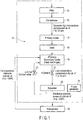
- FIG. 1 is a block diagram schematically showing an air refrigeration device including an expander according to the first embodiment.
- an air refrigeration device 11 comprises a compressor 12 with an entry-side filter 10 provided in an air-intake side, a primary cooler (heat exchanger) 14 connected to an exhaust side of the compressor 12, a drier 16, a secondary cooler (heat exchanger) 18 connected to an exhaust side of the drier 16, an expander 20 which cools the cold air sent from the secondary cooler by adiabatic expansion, and a power generator 75 drivable with regenerative energy of the expander 20.
- a control valve 21 is provided between the secondary cooler 18 and the expander 20, to adjust the flow of air.
- the exhaust side of the expander 20 is communicated to a refrigerator (freezer) 22 in which, for example, items to be cooled, such as perishable foods and frozen food, are accommodated. Further, a part of the exhaust side of the expander 20 is connected to the secondary cooler 18 through a control valve 23, and an exhaust side of the freezer 22 is further connected to the secondary cooler 18.
- the filter 10, the compressor 12, the primary cooler 14, the drier 16, the secondary cooler 18 and the expander 20 may be placed either indoor or outdoor.
- the air refrigeration device 11 indoor or outdoor natural air is taken through the filter 10 into the compressor 12, where it is adiabatically compressed into high-temperature, high-pressure air of about 7 to 10 atmospheres, and then discharged from the compressor 12. After the compression the high-temperature, high-pressure air is sterilized by its own heat. Subsequently, the high-temperature, high-pressure air is sent to the primary cooler 14, where it is cooled by room temperature air to room temperature, and then subjected to removal of water content by the drier (chemical drier, a membrane dryer or the like) 16 in moisture. Furthermore, the air is cooled to a negative temperature zone by the secondary cooler 18, into low-temperature, high-pressure dry air of about 7 to 10 atmospheres.
- the returning cold air from the freezer 22 and controlled cold air from the expander 20 can be used by the secondary cooler 18 to improve the air cooling efficiency.
- the low-temperature, high-pressure air sent from the secondary cooler 18 is taken into the expander 20, where it is adiabatically expanded into a cold air of even lower temperature, for example, of -100°C.
- the cold air (positive-pressure cold air) is discharged from the expander 20 to be supplied to the freezer 22. With this operation, the inside of the freezer 22 is cooled to -80°C at a positive pressure. Excessive cold air in the freezer 22 is returned to the secondary cooler 18 and after passing the secondary cooler 18, it is released to the atmosphere by the positive pressure.
- FIG. 2 is a perspective view showing an appearance of the expander
- FIG. 3 is a perspective view showing an appearance the expander from back side
- FIG. 4 is a perspective view of the expander, showing an internal structure thereof
- FIG. 5 is a front view of the expander.
- the expander 20 comprises a support frame 24, a cylinder 26 attached onto the support frame 24, a cylinder head 28 fixed to the cylinder so as to close an upper end opening of the cylinder 26, a piston 30 arranged to be ascendable/descendable (perpendicularly reciprocative) in the cylinder 26, a plurality of valve mechanisms 40 provided in the cylinder 26 and the cylinder head 28, a drive shaft (crankshaft) 50 rotatably supported by the support frame 24, and an XY-separation crank mechanism 60 which converts the reciprocating motion of the piston into a rotary motion to be transmitted to the crankshaft.
- the support frame 24 comprises a rectangular base frame 25 including a pair of legs, a rectangular first base plate 27a detachably attached to a front side of the base frame 25 so as to close a front-side opening of the base frame, a rectangular second base plate 27b fixed to a back side of the base frame so as to close a back side opening of the base frame, and a pair of support plates 31a and 31b to stand on an upper wall of the base frame 25 to face each other in parallel with an interval therebetween.
- the base frame 25 includes a bottom wall 25a and an upper wall 25b expanding substantially horizontally, and two sidewalls 25c expanding perpendicularly between the bottom wall 25a and the upper wall 25b, which are integrated as one, and a pair of legs 29 formed to have a flange shape in an lower end of each sidewall.
- the cylinder 26 is fixed at substantially the center of the upper wall 25b of the base frame 25 and extends upwards from the base frame 25 in a vertical direction.
- the cylinder head 28 is fixed to the upper end of the cylinder to cover the upper end opening of the cylinder 26.
- the cylinder 26 has an outer shape of a prism, and interposed between a pair of support plates 31a and 31b to be supported therebetween.
- a partition 32 is formed near the lower end of the cylinder 26 and the lower-end side opening of the cylinder 26 is closed by the partition 32.
- the cylindrical piston 30 is arranged to be slidable between the partition 32 and the cylinder head 28.
- a perimeter of the piston 30 is provided with a plurality of piston rings, and these piston rings are airtightly attached to an inner circumferential surface of the cylinder 26.
- a first expansion-compression chamber 26a is defined by the piston 30 and the cylinder head 28, and also a second expansion-compression chamber is defined by the piston 30 and the partition 32.
- the piston 30 ascends and descends the inside of the cylinder 26, that is, reciprocates in a shaft direction (Y-axis direction) of the cylinder 26, to increase and decrease the volume of the first expansion-compression chamber 26a and that of the second expansion-compression chamber 26b alternately, thus establishing the so-called double-action piston.
- the piston rod 34 is coupled with the piston 30, or they are formed integrally as one unit.
- the piston rod 34 extends from the piston 30 into the base frame 25 while passing through a circular first through-hole 36a formed in the partition 32 and a circular second through-hole 36b formed at a center of the upper wall 25b of the base frame 25.
- the piston rod 34 is formed to be coaxial with the cylinder 26 so as to extend in the vertical direction. Further, for example, two rod gaskets 37 are engaged to the first through-hole 36a of the partition 32, and the piston rod 34 is airtightly put through the rod gaskets 37.
- thermal insulation members for example, thermal-insulating sheets 38 of a fluoro-resin are arranged, respectively.
- the heat-insulating sheets 38 insulate against heat propagating from the exterior, for example, from the cylinder-head 28 side or the base frame 25 side to the cylinder 26 to maintain the cylinder 26 at low temperature.
- the crankshaft 50 extends in a direction perpendicularly intersecting a referential plane including a central axis (a moving shaft, Y-axis) of the piston 30.
- both axial ends of the crankshaft 50 are rotatably supported by a first bearing 38a attached to the first base plate 27a of the support frame 24 and a second bearing 38b attached to the second base plate 27b, respectively.
- the crankshaft 50 is located at substantially a center of the base frame 25 to extend in an direction perpendicularly intersecting the first and second base plates 27a and 27b, and is rotatably supported by the support frame 24 around an axis perpendicularly intersecting the central axis of the piston 30.
- crankshaft 50 projects outward from the first base plate 27a, and a large-diameter output wheel (flywheel) 52 is attached coaxially to the projecting end.
- the other end of the crankshaft 50 projects outward from the second base plate 27b and a driving pulley 53 is attached coaxially to the projecting end.
- the output wheel 52 and the driving pulley 53 rotate together with the crankshaft 50.
- FIG. 6 is a perspective view showing the crankshaft and the crank wheel
- FIG. 7 is a plan view of the crankshaft and the crank wheel
- FIG. 8 is an exploded perspective view showing the crankshaft and a crank connection plate.
- crank webs (a crank arm and a counter weight) 54a and 54b are fixed in a middle portion of the crankshaft 50, and further a crank wheel 57 which acts equivalently as a crankpin is fixed between the crank webs 54a and 54b.
- the central axis of the crank wheel 57 is located in parallel to the crankshaft 50 and also eccentrically with respect to the central axis of the crankshaft.
- Counterweights of the crank webs 54a and 54b are arranged to opposite the crank wheel 57 by 180 degrees.
- the crank wheel 57 and the crank webs 54a and 54b are arranged in the base frame 25 and they are eccentrically rotate around the crankshaft 50 according to the rotation of the crankshaft 50.
- crankpin a large-diameter crank wheel as the crankpin
- a large amount of eccentricity can be created at the end of the crank wheel, and thus the moving stroke of the piston, which will be described later, can be enlarged.
- the Z-mechanism XY-separation crank mechanism 60 is provided between the piston 30 and the crankshaft 50 to convert the Y-axial reciprocating motion in of the piston 30 into the rotary motion of the crankshaft 50 mutually and vise versa, to be transmitted.
- a driving force is input to the piston 30 by the pressurized air expanding within the cylinder 26, and the piston 30 reciprocates along the Y-axis.
- the Z-mechanism XY-separation crank mechanism 60 converts the reciprocating motion of the piston 30, which is the driving input, into the rotary motion to be transmitted to the crankshaft 50, thereby applying the rotating output to the crankshaft 50.
- the XY separation crank mechanism 60 comprises a support member (L-type combinatory member) 62 provided to be reciprocative along the Y-axis in the reference plane including the central axis (moving shaft, Y-axis) of the piston 30, and a crank connection member (crank connection plate) 64 attached to the support member 62 so as to be reciprocative in a second direction (X-axis) intersecting perpendicularly with the Y-axis direction in the reference plane, and a coupling member 66 which couples the piston 30 and the support member 62 with each other.
- the moving central shaft (Y-axis direction) of the support member 62, the moving central shaft (X-axis direction) of the crank connection member 64, and the moving central shaft (Y-axis direction) of the coupling member 66 are located in the reference plane.
- the support member 62 is formed into, for example, an L shape and includes a first support portion 62a extending in the Y-axis direction and a second support portion 62b extending in the X-axis direction from one end (here, the upper end) of the first support portion 62a.
- a first linear slider 67a is fixed to the first support portion 62a, and a guiderail 68a is fixed to an inner surface of one of the sidewalls 25c of the base frame 25 to extend in the Y-axis direction.
- the first linear slider 67a is reciprocatively supported and guided to the guiderail 68a.
- the first support portion 62a is supported by the base frame 25 reciprocatively in the Y-axis.
- a guiderail 68b extending in the X-axis direction is being fixed to the second support portion 62b of the support member 62.
- Two second linear sliders 67b are attached to the crank connection member 64 so as to be arranged along the X-axis.
- the second linear sliders 67b are reciprocatively supported and guided to the guiderail 68b.
- the crank connection member 64 is supported by the support member 62 reciprocatively along the X-axis.
- a balance weight (stopper) 63 is fixed to the extending end (the end opposite to the first support portion) of the second support portion 62b.
- the first and the second linear sliders 67a and 67b may include ball bearings built therein and rotatably contacting the guiderails, respectively.
- the crank connection member 64 is formed, for example, into substantially a ring shape and includes a circular through-hole 70.
- the crank connection member 64 is formed dividable into a first half portion 64a and a second half portion 64b with a dividing surface 65 including the center of the through-hole 70, and the second half portion 64b is fixed to the first half portion 64a with a screw or the like.
- the second linear sliders 67b in pair are fixed to a flat part of the first half portion 64a.
- crank wheel 57 of the crankshaft 50 is put through the through-hole 70 of the crank connection member 64 so as to be rotatable via a bearing such as ball bearing or plain bearing 71.
- a bearing such as ball bearing or plain bearing 71.
- the coupling member 66 is formed to have a slender coupling rod, for example, and one end thereof is coupled with the piston rod 34 through a support pin, and the other end is coupled with the second support portion 20b of the support member 62.
- the coupling member 66 is integrated with the support member 62 as one unit.
- the coupling member 66 extends coaxially with the central axis (moving shaft) of the piston 30.
- the coupling member 66 reciprocates integrally with the support member 62 along the Y-axis to reciprocate the piston 30 along the Y-axis.
- the expander 20 including the Z-mechanism XY-separation crank mechanism 60 with the above-described structure operates as follows. That is, as the piston 30 reciprocates along the Y-axis by expansion of the compressed air introduced to the cylinder 26, the reciprocating motion is transmitted to the support member 62 through the piston rod 34 and the coupling member 66 and is separated into a Y-axial movement and an X-axial movement by the XY-separation crank mechanism 60. More specifically, the support member 62 is reciprocated together with the crank connection member 64 along the Y-axis by the first linear slider 67a, and the crank connection member 64 is reciprocated along the X-axis by the second linear slider 67b. Thus, the crank wheel 57 rotates eccentrically around the crankshaft 50 to apply a rotating output to the crankshaft 50.
- the power generator 75 is attached to an outer surface of the sidewall 25c of the base frame 25.
- An input shaft 75a of the power generator 75 is engaged with the output wheel 52 via a plurality of pulleys or a row of pulleys 91.
- the rotating output of the crankshaft 50 rotates the output wheel 52 and is input into the power generator 75 via the row of pulleys 91.
- the input shaft 75a of the power generator 75 is rotated to generate power.
- the cylinder head 28 includes a first inlet port 42a and a first outlet port 42b which communicate to the first expansion-compression chamber 26a of the cylinder 26. Respective ends of the first inlet port 42a and the first outlet port 42b are opened a bottom surface of the cylinder head 28 and the other ends thereof are opened to the both sides of the cylinder head 28, respectively.
- the partition 32 of the cylinder 26 includes a second inlet port 44a and a second outlet port 44b communicating to the second expansion-compression chamber 26b of the cylinder 26. Respective ends of the second inlet port 44a and the second outlet port 44b are opened to a top surface of the partition 32 and the other ends are opened to the front surface face side of the cylinder 26, respectively.
- the valve mechanism of the expander 20 comprises a first inlet-side XY-separation valve mechanism 46 which opens/closes the first inlet port 42a, a first outlet-side valve mechanism 48 which opens/closes the first outlet port 42b, a second inlet-side XY-separation valve mechanism 54 which opens/closes the second inlet port 44a and a second outlet-side valve mechanism 56 which opens/closes the second outlet port 44b.
- FIG. 9 is an enlarged side view of the cylinder head, the first inlet-side XY-separation valve mechanism and the first outlet-side valve mechanism
- FIG. 10 is a perspective view showing the first inlet-side XY-separation valve mechanism.
- the first inlet-side XY-separation valve mechanism 46 comprises a suction valve (for example, a mushroom valve) 72a guided to be ascendable/descendable in the Y-axis direction (third direction) by a valve guide 70a, which opens/closes an opening of the first inlet port 42a on the side of the first expansion-compression chamber 26a, a coiled spring (for example, helical compression spring) 74a which urges the suction valve 72a toward the close position side, and an XY-separation drive mechanism 77 coupled with a stem-extending end of the suction valve 72a, which drives the suction valve 72a to open/close.
- the stem of the suction valve 72a is airtightly put through a ceiling 76a and projects upward from the cylinder head 28.
- the XY-separation drive mechanism 77 comprises a Y-axis separation slider (combinatory member) 78a fixed to the stem extending end of the suction valve 72a and movable in the Y-axis direction together with the suction valve 72a as one unit, a fulcrum hinge 80a provided to stand on the cylinder head 28 and extend in the Y-axis direction, a rocker arm 82a swingably supported by an extending end of the fulcrum hinge 80a, an X-axis separation slider (power-point block) 84a swingably supported by one end (power point) of the rocker arm 82a, a cam follower (roller) 85a rotatably supported by the other end (point of action) of the rocker arm 82a, and a first air inlet cam 86a rotatably supported by the support frame 24 and rotatably contacting the cam follower 85a.
- a Y-axis separation slider (combinatory member) 78a fixed to the stem
- the Y-axis separation slider 78a is formed into, substantially, a rectangular block shape, and includes side surfaces expanding in the Y-axis direction and a top surface expanding in the X-axis direction.
- the Y-axis linear slider 87a extending in the Y-axis direction is fixed on the side surface of the Y-axis separation slider 78a or it is formed integrally with the Y-axis separation slider 78a as one unit.
- the X-axis guiderail 88a extending in the X-axis direction is fixed to the top face of the Y-axis separation slider 78a.
- the Y-axis guiderail 90a extending in the Y-axis direction is fixed on a side surface of the fulcrum hinges 80a, which opposes the Y-axis separation slider 78a.
- the Y-axis linear slider 87a of the Y-axis separation slider 78a is guided and supported by the Y-axis guiderail 90a so as to be slidable along the Y-axis.
- the X-axis linear slider 92a is fixed to the bottom surface of the X-axis separation slider 84a, which opposes the Y-axis separation slider 78a, or it is formed integrally with the X-axis separation slider 84a as one unit.
- the X-axis linear slider 92a is guided and supported by the X-axis guiderail 88a of the Y-axis separation slider 78a so as to be slidable in the X-axis direction.
- Y-axis linear slider 87a and the X-axis linear slider 92a may each include a built-in ball bearing rotatably contacting the respective guiderail.
- the extending end portion (upper end portion) of the fulcrum hinges 80a is curved towards the Y-axis separation slider 78a (XC-axis separation slider 84a side) with respect to the Y-axis direction. Therefore, the rocker arm 82a is swingably supported by the fulcrum hinge 80a on a power-point side with respect to the longitudinal central portion, that is, on a side of the X-axis separation slider 84a.
- a distance L1 between the power point (the cam follower) and the fulcrum is set to be sufficiently greater than a distance L2 of the fulcrum and power point (engaging position of the X-separation slider 84a and the rocker arm 82a) (L1 > L2).
- a first inlet-side coupler 93a is fitted to an inlet-side end opening of the inlet port 42a.
- a pipe (supply line) from the secondary cooler 18 is connected to the first inlet-side coupler 93a to guide low-temperature, high-pressure air to the first inlet port 42a from the secondary cooler 18.
- the first suction valve 72a is urged by the coil spring 74a so as to descend and tightly attach to the seat (valve seat) of the first inlet port 42a, thereby closing the first inlet port 42a.
- the first air inlet cam 86a rotates to push the cam follower 85a of the rocker arm 82a downward at a predetermined timing.
- the rocker arm 82a pivots clockwise around the fulcrum, whereas the X-axis separation slider 84a pivots upwards.
- the X-axis separation slider 84a pulls up the Y-axis separation slider 78a and the suction valve 72a upwards along the Y-axis, and simultaneously slides in the X-axis direction with respect to the Y-axis separation slider 78a. That is, the rotating motion of the X-axis separation slider 84a is divided into a Y-axis movement and an X-axis movement and only the Y-axis movement is transmitted to the Y-axis separation slider 78a.
- the Y-axis separation slider 78a and the first suction valve 72a reciprocate along the Y-axis by the Y-axis linear slider 87a to open/close the first inlet port 42a.
- the cam follower 85a is brought into rotatable contact with a small-diameter portion of the first air inlet cam 86a to reduce the pressure by the air inlet cam 86a. Therefore, with the urging force of the coil spring 74a, the first suction valve 72a and the Y-axis separation slider 78a are moved downward in the Y-axis direction to close the first inlet port 42a. Meanwhile, the rocker arm 82a pivots in the counterclockwise direction, and the X-axis separation slider 84a moves downward together with the Y-axis separation slider 78a, while sliding in the to X-axis direction.
- the first exhaust side valve mechanism 48 includes a discharge valve (for example, a mushroom valve) 96a ascendably/descendably guided along the Y-axis (third direction) by a valve guide 94a embedded in the cylinder head 28.
- a stem of the discharge valve 96a is airtightly put through the ceiling 95a so as to project upwards from the cylinder head 28.
- the discharge valve 96a ascends/descends in the Y-axis direction to open/close the end opening of the first outlet port 42b, which is on the side of the first expansion-compression chamber 26a.
- the first exhaust-side valve mechanism 48 includes a slide drive mechanism 98 coupled with a coiled spring (for example, helical compression spring) 97a which urges the discharge valve 96a towards the close position side and with the stem extending end of the discharge valve 96a, to open/close the discharge valve 96a.
- a coiled spring for example, helical compression spring
- the slide drive mechanism 98 comprises a Y-axis slider 100a fixed to the stem extending end of the discharge valve 96a to moves in the Y-axis direction integrally with the discharge valve 96a as one unit, a cam follower (roller) 102a rotatably attached to the Y-axis slider 100a, a slide holder 104a provided to stand on the cylinder head 28 and extend in the Y-axis direction, and a first outlet cam 105a rotatably supported by the support frame 24 and rotatable contacting the cam follower 102a.
- a cam follower (roller) 102a rotatably attached to the Y-axis slider 100a
- a slide holder 104a provided to stand on the cylinder head 28 and extend in the Y-axis direction
- a first outlet cam 105a rotatably supported by the support frame 24 and rotatable contacting the cam follower 102a.
- the Y-axis slider 100a is formed into substantially a rectangular block shape and includes a side surface expanding in the Y-axis direction.
- a Y-axis linear slider 106a expanding in the Y-axis direction is fixed on a side surface of the Y-axis slider 100a or is formed integrally with the Y-axis slider 100a as one unit.
- a Y-axis guiderail 108a extending in the Y-axis direction is fixed on a side surface of the slide holder 104a, which opposes the Y-axis slider 100a.
- the Y-axis linear slider 106a of the Y-axis slider 100a is slidably guided and supported by the Y-axis guiderail 108a in the Y-axis direction.
- the Y-axis linear slider 106a may include a built-in ball bearing rotatably contacting the Y-axis guiderail 108a.
- a first exhaust-side coupler 109a is fitted to an outlet-side end opening of the first outlet port 42b.
- a pipe discharge line is connected to the first exhaust-side coupler 109a to send therethrough the cold air discharged from the expander 20 to the freezer 22.
- the first discharge valve 96a and the Y-axis slider 100a are urged by the coil spring 97a an thus the first discharge valve 96a ascends and tightly attaches to the seat (valve seat) of the first outlet port 42b, thereby closing the first outlet port 42a.
- the first outlet cam 105a rotates to push the cam follower 102a of the Y-axis slider 100a downward at a predetermined timing.
- the Y-axis slider 100a slides downward along the Y-axis to move the first discharge valve 96a downward along the Y-axis therewith, to open the first outlet port 42b.
- the cam follower 102a is brought into rotatable contact with a small-diameter portion of the first outlet cam 105a. Therefore, with the urging force of the coil spring 97a, the first discharge valve 96a and the Y-axis slider 100a are moved upward along the Y-axis, and the first discharge valve 96a closes the first outlet port 42b.
- the second inlet-side XY-separation valve mechanism 54 which opens/closes the second inlet port 44a has a structure similar to that of the first inlet-side XY-separation valve mechanism 46 described above except the following. That is, the first inlet-side XY-separation valve mechanism 46 has the so-called vertical structure in which the first suction valve and the Y-axis separation slider ascend/descend along the Y-axis, whereas the second inlet-side XY-separation valve mechanism 54 has the so-called horizontal structure in which the second suction valve and the separation slider reciprocate along the X-axis.
- the second inlet-side XY-separation valve mechanism 54 comprises a second suction valve (for example, a mushroom valve) 72b guided reciprocatively along the X-axis (the fourth direction) by the valve guide, to open/close the end opening of the second inlet port 44a, on the side of the second expansion-compression chamber 26b, a coiled spring (for example, a compression spring) 74b which urges the second suction valve 72b toward the close position side, and an XY separation drive mechanism coupled with the stem extending end of the second suction valve 72b, to open/close the second suction valve 72b.
- the stem of the second suction valve 72b is airtightly put through the ceiling 76b, to project to a side of the cylinder 26.
- the XY separation drive mechanism comprises an X-axis separation slider (combinatory member) 78b fixed to the stem extending end of the second suction valve 72b so as to be movable along the X-axis therewith as one unit, a fulcrum hinge 80b provided to stand on the cylinder 26 and extend in the X-axis direction, a rocker arm 82b swingably supported by the extending end of the fulcrum hinge 80b, a Y-axis separation slider (power point block) 84b swingably supported by one end (power point) of the rocker arm 82b, a cam follower (roller) 85b rotatably supported by the other end (point of application) of the rocker arm 82b and a second air inlet cam 86b rotatably supported by the support frame 24 and rotatably contacting the cam follower 85b.
- the X-axis linear guide of the X-axis separation slider 78b is guided and supported slidably along the X-axis by an X-axis guiderail attached to the fulcrum hinge 80b.
- the Y-axis linear slider of the Y-axis separation slider 84b is guided and supported slidably along the Y-axis by a Y-axis guiderail of the X-axis separation slider 78b.
- a second inlet-side coupler 93b (see FIG. 2 ) is fitted to the inlet-side end opening of the second inlet port 44a.
- a pipe (supply line) from the secondary cooler 18 described above is connected to this second inlet-side coupler 93b and low-temperature, high-pressure air is guided to the inlet port 44a from the secondary cooler 18.
- the second inlet-side XY-separation valve mechanism 54 which has the above-described structure operates in a similar fashion to that of the first inlet-side XY-separation valve mechanism 46 described above, to open/close the second inlet port 44a.
- the second outlet-side valve mechanism 56 which opens/closes the second outlet port 44b has a stricture similar to that of the first outlet-side valve mechanism 48 described above.
- the first outlet-side valve mechanism 48 has the so-called vertical structure in which the first discharge valve and the Y-axis slider ascend/descend along the Y-axis
- the second outlet-side valve mechanism 56 has the so-called horizontal structure in which the second discharge valve and the X-axis slider reciprocate along the X-axis.
- the second outlet-side XY-separation valve mechanism 56 comprises a second discharge (for example, a mushroom valve) 96b guided reciprocatively along the X-axis (the fourth direction) by the valve guide embedded in the cylinder 26.
- the stem of the discharge valve 96b is airtightly put through the ceiling, to project to a side of the cylinder 26.
- the discharge valve 96b reciprocates along the X-axis to open/close the end opening of the second outlet port 44b, located on the side of the second expansion-compression chamber 26b.
- the second outlet-side valve mechanism 56 comprises a coiled spring (for example, a compression spring) 97b which urges the discharge valve 96b toward the close position side, and a slide drive mechanism coupled with the stem extending end of the discharge valve 96b to open/close the discharge valve 96b.
- a coiled spring for example, a compression spring
- the slide drive mechanism comprises an X-axis slider 100b fixed to the stem extending end of the discharge valve 96b to be movable along the X-axis integrally with the discharge valve 96b as one unit, a cam follower (roller) rotatably attached to the X-axis slider 100b, a slide holder 104b provided to stand on the cylinder 26 so as to extend in the X-axis direction and a second outlet cam 105b rotatably supported by the support frame 24 and rotatably contacting the cam follower.
- the X-axis linear slider of the X-axis slider 100b is guided and supported slidably along the X-axis by the X-axis guiderail provided in the slide holder 104b to extend in the X-axis direction.
- a second outlet-side coupler 109b (see FIG. 2 ) is fitted to the outlet-side end opening of the second outlet port 44b.
- a pipe discharge line is connected to the second outlet-side coupler 109b to send therethrough the cold air discharged from the expander 20 to the freezer 22.
- the second outlet-side valve mechanism 56 having the above-described structure operates in a similar manner to that of the first outlet-side valve mechanism 48 described above, to open/close the second outlet port 44b.
- a plurality of camshafts are rotatably attached to the support frame 24, and various cams described above are attached to the camshafts, respectively. More specifically, a first inlet camshaft 110a and a first outlet camshaft 112a are supported rotatably by a pair of support plates 31a and 31b of the support frame 24. The first inlet camshaft 110a and the first outlet camshaft 112a are provided above the cylinder head 28 to be parallel to each other.
- the first air inlet cam 86a is fixed to the first inlet camshaft 110a so as to rotate integrally with the camshaft as one unit.
- the first outlet cam 105a is fixed to the first outlet camshaft 112a so as to rotate integrally with the camshaft as one unit.
- One end portion of the first inlet camshaft 110a and one end portion of the first outlet camshaft 112a project from the support plate 31b toward the back side.
- a first driven pulley 124a and a second driven pulley 124b are attached to these end portions, respectively, to be rotatable integrally with the camshafts as one unit.
- a second inlet camshaft 110b and a second outlet camshaft 112b are rotatably supported by the pair of support plates 31a and 31b of the support frame 24.
- the second inlet camshaft 110b and the second outlet camshaft 112b are provided respectively in both sides of the cylinder 26 to be in parallel to each other.
- the second air inlet cam 86b is fixed to the second inlet camshaft 110b so as to rotate integrally with the camshaft as one unit.
- the second outlet cam 105b is fixed to the second outlet camshaft 112b so as to rotate integrally with the camshaft as one unit.
- One end portion of the second inlet camshaft 110b and one end portion of the second outlet camshaft 112b project from the support plate 31b toward the back side.
- a third driven pulley 124c and a fourth driven pulleys 124d are attached to these end portions, respectively, to be rotatable integrally with the camshafts as one unit.
- a plurality of tension pulleys 126 are rotatably attached to the back side of the support plate 31b, and the back side of the second base plate 27b.
- a loop-like timing belt 128 is fasten over first to fourth driven pulleys 124a to 124d, four tension pulleys 126, and a passive belt pulley 53 attached to the crankshaft.
- the first to fourth driven pulleys 124a to 124d are rotated synchronously by the timing belt 128.
- the first and second inlet camshafts 110a and 110b and the first and second outlet camshafts 112a and 112b rotate, and along with these camshafts, the first and second air inlet cams 86a and 86b and the first and second outlet cams 105a and 105b rotate to open/close the valves of the respective valve mechanisms at a predetermined cycle and timing.
- the crankshaft 50 is rotated with a motor or the like, which is not shown in the drawings, at the time of start up, to ascend/descend the piston 30.
- the first suction valve 72a is opened to supply the low-temperature, high-pressure air from the first inlet port 42a into the first expansion-compression chamber 26a.
- the first suction valve 72a is closed, as the piston 30 descends toward a lower dead center, the volume of the first expansion-compression chamber 26a increases gradually, and accordingly, the low-temperature, high-pressure air inside adiabatically expands.
- the air is cooled to a cryogenic temperature of -80 to -100°C.
- the first discharge valve 96a is opened and the cooling air (cold air) in the first expansion-compression chamber 26a is pushed with the piston 30, to be discharged to the pipe from the first outlet port 42b and the first discharge coupler 109a.
- the discharged cooling air is emitted into the freezer 22 through the pipe to cool the inside of the freezer 22.
- the second suction valve 74b is opened to supply the low-temperature, high-pressure air to the second expansion-compression chamber 26b from the second inlet port 44a.
- the second suction valve 74b is closed, as the piston 30 ascends toward the upper dead center, the volume of the second expansion-compression chamber 26b increases gradually, and accordingly, the low-temperature and high-pressure inside adiabatically expands.
- the air is cooled to a cryogenic temperature of -80 to -100°C.
- the second discharge valve 96b When the piston 30 moves from the lower dead center toward the upper dead center, the second discharge valve 96b is opened, and the cooling air (cold air) in the second expansion-compression chamber 26b is pushed with the piston 30 to be discharged to the pipe from the second outlet port 44b and the second inlet coupler 109b.
- the discharged cooling air is emitted into the freezer 22 through the pipe to cool the inside of the freezer 22.
- Part of the cold air discharged from first and second outlet ports 42b and 44b is sent to the secondary cooler 18 through the control valve 23.
- the piston 30 After the start of the expander 20, the piston 30 is driven by the low-temperature, high-pressure air, and its reciprocating motion is converted into rotary motion with the XY separation crank mechanism 60, to rotate the crankshaft 50. That is, the crankshaft 50 is rotated by the expansive power of high-pressure air, and the power generator 75 is driven by this turning force to obtain the regenerative power.
- the reciprocating motion of the piston can be converted into rotary motion by the XY separation crank mechanism, to be transmitted to the crankshaft. Therefore, as compared to the mechanism using a swinging connecting rod (coupling rod) or a slider crank, the side thrust loss (friction loss) and vibration of the piston or cylinder can be greatly suppressed. Since there is no friction loss, the vibration can be suppressed to low, thereby enabling a high-speed operation. At the same time, there is no heat loss by the side thrust loss, thereby making it possible to significantly improve the efficiency, and also to easily make the structure smaller. According to this embodiment, with use of the double-acting pistons and cylinders, the volume becomes twice as much to have a better efficiency, and therefore an effect of 3 times higher than usual cases can be expected.
- the power is transmitted by the Z-mechanism XY-separation crank mechanism and the direct-acting connection member.
- the cylinder part and the crank part can be detached from each other, and therefore it is easy to provide a thermal insulator in a gap therebetween, thereby making it possible to minimize the heat transfer.
- the heat loss can be reduced further to improve the efficiency even further.
- the space factor is reduced to a half, thereby making it easy to make the expander smaller.
- valve mechanism With use of an XY-separation valve mechanism as the valve mechanism, the side thrust acting on the valve can be eliminated to be able to reduce the heat loss caused by friction loss and avoid deformation of the valve by the side thrust itself.
- the valve operations an exact linear motion by the linear guide of the valve-opening/closing directions, and thus the valve and the valve seat tightly attach to each other with precision, thereby improving the sealing properties and realizing a precise opening-and-closing operation. Further, the valve mechanism can achieve high efficiency and excellent durability.
- the working oil of the valve also serves as lubricating oil, it is easy to stop unnecessary rotation of the valve, and the valve can be easily made into a type of solenoid-type electromagnetic mechanism.
- the cooling air can be supplied and discharged precisely and at high speed with high sealing properties.
- the expansion rate and air cooling efficiency of the expander can be further improved.
- the expander of this embodiment can obtain a larger expansion ratio, and therefore various adjustment mechanisms including the bypass can be simplified. Further, the device can be freely designed from a large- to a small-size type. The rotation of the expander can be arbitrarily changed to be able to easily adjust the temperature. It can be manufactured at low cost and rigid as compared to the turbine type.
- the expansion work of the expander is recoverable as regeneration energy with a power generator, for example. Since the expansion energy can be used as the load at a ratio of 1 : 1, the energy can be collected substantially 100% while generating the cold air. For example, with an expander having 700W of shaft horsepower, it has been actually monitored that a recovery power of 500W was achieved.
- the piston and valve can be operated in a perfect parallel motion. Therefore, when using a small piston of about 30 mm diameter ( ⁇ ) or a large-sized piston of 500 mm diameter, excellent sealing properties can be achieved, thereby realizing a lossless and efficient operation. Moreover, it is easy to remodel it into a multistage type, achieving high flexibility to arbitrarily remodel into a 2-, 3- or 8-cylinder type. Further, since there is no side thrust loss, it is possible to manufacture the piston and the valve easily from ceramics. With ceramics, it is possible to reduce the weight of the device and also improve the thermal insulating properties.
- the expander of this embodiment it is possible to simplify the structure as compared to the conventional air refrigeration device, thereby making it possible to provide a low-cost air refrigeration device.
- the chiller is no longer necessary inside the air conditioner, but only an air outlet for mixed air with the room temperature air is required, thereby making it possible to miniaturize the air conditioner.
- the air refrigeration device of this embodiment when the compressor pressurizes to 1 MPa, the room-temperature air become to have 200°C, and thus the viruses and bacteria in the air can be easily destroyed for sterilization. Since the sterilization of viruses and bacteria is easy, a clean room can be easily prepared. For operating rooms or semiconductor-factories, the filter can be miniaturized, thereby making it possible to reduce the total cost. Further, since the cold air is discharged from the expander into the freezer, the inside of the freezer has a positive pressure and therefore the air does not enter the freezer from the exterior. Therefore, if the freezer is formed to have such a simple structure, a sufficient refrigeration function can be exhibited. Thus, the manufacturing cost of the freezer can be significantly reduced.
- FIG. 11 is a block diagram schematically showing an air refrigeration device according to the second embodiment.
- an air refrigeration device 11 comprises a compressor 12 with an entry-side filter 10 provided in an air-intake side, a primary cooler (heat exchanger) 14 connected to an outlet side of the compressor 12, a drier 16, a secondary cooler (heat exchanger) 18 connected to an outlet side of the drier 16, an expander 20 which cool the cold air sent from the secondary cooler by adiabatic expansion and a refrigerating unit 200 connected to an outlet side of the expander 20.
- the second embodiment comprises a refrigerating unit 200 in pace of a freezer and the cold air discharged from the expander 20 is directly supplied to the refrigerating unit 200.
- the expander 20 has a structure similar to that of the first embodiment described above.
- the air refrigeration device 11 indoor or outdoor natural air is taken through the filter 10 into the compressor 12, where it is adiabatically compressed into high-temperature, high-pressure air of about 7 to 10 atmospheres, and then discharged from the compressor 12. After the compression the high-temperature, high-pressure air is sterilized by its own heat. Subsequently, the high-temperature, high-pressure air is sent to the primary cooler 14, where it is cooled by room temperature air to room temperature, and then subjected to removal of water content by the drier (chemical drier, a membrane dryer or the like) 16 in moisture. Furthermore, the air is cooled down to a negative temperature zone by the secondary cooler 18, into low-temperature, high-pressure dry air of about 7 to 10 atmospheres.
- the drier chemical drier, a membrane dryer or the like
- the low-temperature, high-pressure air sent from the secondary cooler 18 is taken into the expander 20, where it is adiabatically expanded into a cold air of even lower temperature, for example, of -100°C.
- the cold air (positive-pressure cold air) is discharged from the expander 20 to be supplied to the refrigerating unit 200. Excessive cold air in the refrigerating unit 200 is allowed pass therethrough and then, it is released out to the space where the unit is placed (working room).
- FIG. 13 is a perspective view showing a refrigerating unit
- FIG. 14 is a side view of the refrigerating unit of FIG. 12 .
- the refrigerating unit 200 comprises a belt conveyor 202, which is a conveying line which convey, for example, items to be cooled, such as perishable foods and frozen foods, and a cooler 203 placed to cover at least a part of the belt conveyor 202.
- the cooler 203 comprises two support stands 208 and 210 set on both sides of the belt conveyor 202 and a cooling cover 204 pivotably supported by the support stand 210 with a hinge 212.
- the cooling cover 204 is pivotably supported between a cooling position to cover the belt conveyor 202 as shown in FIG. 13 and an open position to uncover the belt conveyor 202 as shown in FIG. 14 .
- a plurality of current plates 206 are formed in the cooling cover 204.
- a plurality of, for example, two supply holes 216a and 216b are formed in the cooling cover 204 and the air-blow fans 214a and 214b are provided in the supply holes, respectively.
- air-pipes 220a and 220b are connected to the supply holes 216a and 216b, respectively.
- the air-pipes 220a and 220b are formed flexibly and connected respectively to the first outlet-side coupler 109a and the second outlet-side coupler 109b of the expander 20, described above, through a discharge line.
- the cold air discharged from the expander 20 is supplied into the cooling cover 204 through the air-pipes 220a and 220b and is further blown onto items to be cooled, on the belt conveyor 202 by the air-blow fans 214a and 214b.
- the cooling air of -80 to -100°C is directly applied to the items to be cooled, to be able to freeze the items immediately.
- cooling cover 204 is pivotable to the open position. For cleaning, the cooling cover 204 is opened, and the inner side of the cover, the upper surface of the belt conveyor 202 and the like can be easily cleaned.
- the air refrigeration device having the structure described above, items to be cooled can be easily frozen using the refrigerating unit 200 which has a comparatively simple structure. Further, the location of the refrigerating unit 200 may not necessarily be in the freezer or freezer compartment, but it may be freely installed. In addition, the second embodiment can exhibit an effect similar to that of the first embodiment.
- FIG. 15 schematically shows an air refrigeration device according to the third embodiment.
- the air refrigeration device comprises an expander 20 which has the same structure as that of the first embodiment, a compressor 12, an engine 300, a heat exchanger 306 and a power generator 75 connectable with an output side of the expander 20.
- the compressor 12 has the same structure as that of the expander 20 except that the timing for opening/closing of the valve mechanisms 46, 48, 54, and 56 is set appropriately so that it can exhibit the function as a compressor.
- the engine 300 has the same structure as that of the expander 20.
- the engine 300 comprises a first ignition plug 302 which ignites the first expansion-compression chamber of the cylinder 26 and a second ignition plug 304 which ignites the second expansion-compression chamber of the cylinder 26. Further, the timing for opening/closing of the valve mechanisms 46, 48, 54, and 56 is set appropriately so that it can exhibit the function as an engine.
- the crankshaft 50 of the expander 20 is selectively connected to the power generator 75 by a first clutch 308.
- the power generator 75 is selectively connected to the crankshaft 50 of the engine 300 by a second clutch 310.
- the output shaft (crankshaft 50) of the compressor 12 is selectively connected to the crankshaft 50 of the engine 300 by a third clutch 312.
- the heat exchanger 306 is connected to an outlet side of the engine 300.
- An electric apparatus, for example, a lighting apparatus 320 is connectable to the power generator 75.
- the air refrigeration device having the structure described above can be operated in various modes by switching the first to third clutches 308, 310 and 312.
- the air refrigeration device When the first clutch 308 is on, the second clutch 310 is off and the third clutch 312 is on, the air refrigeration device simultaneously generates power while in the air refrigeration mode. More specifically, the low-temperature, high-pressure air is supplied from the compressor 12 to the expander 20, where cryogenic air is generated to be discharged. Simultaneously, with the regenerative energy of the expander 20, the power generator 75 is driven to generate power. The generated power is supplied to the lighting apparatus 320, for example. Further, by driving the engine 300, the compressor 12 can be driven by using the output of the engine 300.
- the air refrigeration device When the first clutch 308 is off, the second clutch 310 is on and the third clutch 312 is off, the air refrigeration device operates in a power generation mode. More specifically, the power generator 75 is driven by the output of the engine 300 to generate power. When electrical power is required but the freezing or refrigeration is not, the priority can be given to the power.
- a power generator may be attached to the expander which has a Z-mechanism XY-separation mechanism, and a power generator may be attached also to the engine 300.
- the power generator can be handled as a load approximately equivalent to a flywheel, unless the electromagnet is turned off and the load is not applied. But by switching with clutches, the equipment can be miniaturized. If the system includes two power generators, the degree of freedom is further improved.
- 2.5 Kw is generated per cooling device, and there are three sets of cooling device, which makes a total of 7.5 Kw, by which the heat source for the gas, etc. of the engine 300 and the compressor 12 can be saved. Since 2.5 Kw is generated automatically, when consuming 1 Kw, a difference of 1.5 Kw of electricity can be sold to a utility.
- gas can be converted directly into cooling and power generation.
- 75 Kw can be saved per unit, and 250,000 Kw is generated, which is equivalent to one unit of nuclear power plant of one million Kw.
- the GDP value global warming index
- the GDP value is decreased from 8500 of chlorofluocarbon to 1, which is significantly advantageous for global environment.
- Such cooling or cooling area is not only for ordinary households, but can improve the efficiency of a wide range of industries including the semiconductor manufacture and the electrochemical fields.
- the present invention is not limited to the embodiments described above but the constituent elements of the invention can be modified in various manners without departing from the spirit and scope of the invention.
- Various aspects of the invention can also be extracted from any appropriate combination of a plurality of constituent elements disclosed in the embodiments. Some constituent elements may be deleted in all of the constituent elements disclosed in the embodiments. The constituent elements described in different embodiments may be combined arbitrarily.
- the support member or the support portion which reciprocatively supports a crank connection member is not limited to a linear slider, but some other support structures may be employed. In place of the linear slider, a dovetail slide support structure may be used. Further, a magnetic levitation system such as a linear motor mechanism can also be introduced to the linear guide of the XY separation crank mechanism. In this case, a further high speed driving can be achieved.
- the expander is not limited to a 1-cylinder type, but may be a 2- or more cylinder type.
- the expander is not limited to the so-called vertical type, but may be of a horizontal type in which the cylinder and piston are arranged horizontally.
Landscapes
- Engineering & Computer Science (AREA)
- Mechanical Engineering (AREA)
- General Engineering & Computer Science (AREA)
- Physics & Mathematics (AREA)
- Thermal Sciences (AREA)
- Compressor (AREA)
- Compressors, Vaccum Pumps And Other Relevant Systems (AREA)
- Valve-Gear Or Valve Arrangements (AREA)
- Chemical & Material Sciences (AREA)
- Analytical Chemistry (AREA)
- Power Engineering (AREA)
Applications Claiming Priority (1)
| Application Number | Priority Date | Filing Date | Title |
|---|---|---|---|
| PCT/JP2014/060041 WO2015151297A1 (ja) | 2014-04-04 | 2014-04-04 | 膨張機およびこれを備える空気冷凍装置 |
Publications (2)
| Publication Number | Publication Date |
|---|---|
| EP3128127A1 true EP3128127A1 (de) | 2017-02-08 |
| EP3128127A4 EP3128127A4 (de) | 2017-10-04 |
Family
ID=54239657
Family Applications (1)
| Application Number | Title | Priority Date | Filing Date |
|---|---|---|---|
| EP14888109.7A Withdrawn EP3128127A4 (de) | 2014-04-04 | 2014-04-04 | Expander und damit ausgestattete luftgefriervorrichtung |
Country Status (6)
| Country | Link |
|---|---|
| US (1) | US10400599B2 (de) |
| EP (1) | EP3128127A4 (de) |
| JP (1) | JP5857324B1 (de) |
| CN (1) | CN106460514B (de) |
| SG (1) | SG11201608324YA (de) |
| WO (1) | WO2015151297A1 (de) |
Families Citing this family (9)
| Publication number | Priority date | Publication date | Assignee | Title |
|---|---|---|---|---|
| KR101778197B1 (ko) * | 2015-05-19 | 2017-09-26 | 여태순 | 확장형 나이프 스키 장치가 구비된 바이크 |
| CN106885679A (zh) * | 2017-04-07 | 2017-06-23 | 西南交通大学 | 一种振动翼栅驱动装置 |
| CN108692905B (zh) * | 2018-06-14 | 2020-11-17 | 江苏东恒光电有限公司 | 一种角度冲击装置 |
| JP6812532B1 (ja) * | 2019-12-24 | 2021-01-13 | 株式会社三井E&Sマシナリー | 往復式圧縮膨張機 |
| CN111706398B (zh) * | 2020-07-31 | 2024-04-09 | 中南大学 | 一种高膨胀比水平对置活塞式膨胀机及控制方法 |
| WO2022067604A1 (zh) * | 2020-09-30 | 2022-04-07 | 周连惠 | 一种压缩空气综合利用系统 |
| GB2604330A (en) * | 2021-02-02 | 2022-09-07 | Pierce Martin Parry John | Air disinfecting machine |
| JP7766094B2 (ja) * | 2021-06-10 | 2025-11-07 | 住友重機械工業株式会社 | 極低温冷凍機および極低温冷凍機の運転方法 |
| CN116357402B (zh) * | 2021-12-28 | 2025-08-12 | 宁波奥克斯电气有限公司 | 活塞式膨胀机和空调器 |
Family Cites Families (27)
| Publication number | Priority date | Publication date | Assignee | Title |
|---|---|---|---|---|
| US8080A (en) | 1851-05-06 | Improved process for the artificial production of ice | ||
| US2405016A (en) * | 1943-07-21 | 1946-07-30 | William H Cook | Piston and cylinder device |
| US3572299A (en) * | 1969-12-15 | 1971-03-23 | Lester Ind Inc | Valve-actuating train for machinery having a cyclicly operated poppet valve |
| US3694109A (en) * | 1970-12-09 | 1972-09-26 | Patrick Joseph Walls | Internal combustion engine or compressor |
| US4226169A (en) * | 1978-06-05 | 1980-10-07 | The United States Of America As Represented By The United States Department Of Energy | Adjustable expandable cryogenic piston and ring |
| JPS57150748U (de) * | 1981-03-18 | 1982-09-21 | ||
| US4520632A (en) * | 1982-10-25 | 1985-06-04 | Centrifugal Piston Expander, Inc. | Method and apparatus for extracting heat and mechanical energy from a pressured gas |
| JPS59231255A (ja) * | 1983-06-14 | 1984-12-25 | Shizuo Yoshida | ピストン摺動子式クランク軸回転機構 |
| US4580413A (en) * | 1985-06-06 | 1986-04-08 | Air Products And Chemicals, Inc. | Pressurized fluid lift system for a cryogenic freezer |
| JPS62217060A (ja) * | 1986-03-17 | 1987-09-24 | 株式会社東芝 | 冷却機用膨張エンジン |
| JPH01139958A (ja) * | 1987-11-26 | 1989-06-01 | Nippon Denso Co Ltd | 膨脹機の弁構造 |
| US5092131A (en) * | 1990-02-14 | 1992-03-03 | Kabushiki Kaisha Toshiba | Gas expansion engine |
| MD950436A (ro) * | 1994-03-18 | 1998-01-31 | Yoshiki Industrial Co., Ltd | Dispozitiv de transformarea reciprocă a mişcării de rotaţie în mişcare rectilinie alternativă |
| GB2287766B (en) * | 1994-03-18 | 1998-01-28 | Yoshiki Kogyo Kk | Apparatus for mutual conversion between circular motion and reciprocal motion |
| JP2929280B2 (ja) * | 1996-10-02 | 1999-08-03 | 三菱電機冷熱設備株式会社 | 冷凍装置 |
| AUPO641097A0 (en) * | 1997-04-24 | 1997-05-22 | Mitchell, William Richard | Compact internal combustion engine |
| JP3331198B2 (ja) * | 1998-11-27 | 2002-10-07 | 健二 青井 | トンネル式冷却冷凍装置 |
| JP2002318027A (ja) | 2001-04-20 | 2002-10-31 | Shimadzu Corp | 冷凍システム |
| JP2003214103A (ja) * | 2002-01-23 | 2003-07-30 | Makio Nobuaki | 回転力発生装置および回転力発生システム |
| JP3780281B2 (ja) * | 2003-12-25 | 2006-05-31 | Lwj株式会社 | 冷凍システム |
| WO2006060859A1 (en) * | 2004-12-06 | 2006-06-15 | Peter Robert Raffaele | Improved engine and pump |
| SE528784C2 (sv) * | 2005-06-07 | 2007-02-13 | Scania Cv Abp | Anordning för överföring av rörelse från en vipparm till en ventilinrättning hos en förbränningsmotor och en förbränningsmotor innefattande en sådan anordning |
| US8448440B2 (en) * | 2007-03-07 | 2013-05-28 | Thermal Power Recovery Llc | Method and apparatus for achieving higher thermal efficiency in a steam engine or steam expander |
| US20090013681A1 (en) * | 2007-07-12 | 2009-01-15 | Courtright Geoffrey B | Energized Fluid Motor and Components |
| CN102149914B (zh) * | 2009-06-23 | 2013-06-26 | 浪越博道 | 内燃引擎 |
| WO2012144073A1 (ja) * | 2011-04-22 | 2012-10-26 | 有限会社タックリサーチ | Xy分離クランク機構およびこれを備えた駆動装置 |
| JP5393907B1 (ja) | 2012-11-09 | 2014-01-22 | 有限会社タック リサーチ | Xy分離クランク機構およびこれを備えた駆動装置 |
-
2014
- 2014-04-04 SG SG11201608324YA patent/SG11201608324YA/en unknown
- 2014-04-04 JP JP2014517310A patent/JP5857324B1/ja active Active
- 2014-04-04 WO PCT/JP2014/060041 patent/WO2015151297A1/ja not_active Ceased
- 2014-04-04 EP EP14888109.7A patent/EP3128127A4/de not_active Withdrawn
- 2014-04-04 CN CN201480077795.4A patent/CN106460514B/zh not_active Expired - Fee Related
-
2016
- 2016-10-03 US US15/284,160 patent/US10400599B2/en active Active
Also Published As
| Publication number | Publication date |
|---|---|
| SG11201608324YA (en) | 2016-11-29 |
| US20170022810A1 (en) | 2017-01-26 |
| CN106460514A (zh) | 2017-02-22 |
| EP3128127A4 (de) | 2017-10-04 |
| WO2015151297A1 (ja) | 2015-10-08 |
| JP5857324B1 (ja) | 2016-02-10 |
| US10400599B2 (en) | 2019-09-03 |
| JPWO2015151297A1 (ja) | 2017-04-13 |
| CN106460514B (zh) | 2019-10-22 |
Similar Documents
| Publication | Publication Date | Title |
|---|---|---|
| EP3128127A1 (de) | Expander und damit ausgestattete luftgefriervorrichtung | |
| US7784300B2 (en) | Refrigerator | |
| KR101289395B1 (ko) | 가스 평형 극저온 팽창 엔진 | |
| US7603858B2 (en) | Harmonic engine | |
| JP5894663B2 (ja) | ガス圧を均衡させた極低温膨張エンジン | |
| WO2009066178A4 (en) | Heat engines | |
| US11199157B2 (en) | Efficient heat recovery engine | |
| CN101182837A (zh) | 一种双作用自由活塞式膨胀-压缩机组 | |
| US20150184897A1 (en) | Refrigeration apparatus | |
| WO2008156913A2 (en) | Harmonic engine | |
| JP5839519B1 (ja) | Zメカニズムバルブ機構 | |
| CN100359167C (zh) | 一种自由活塞式膨胀-压缩机组 | |
| KR100654660B1 (ko) | 냉각장치 | |
| RU2814992C1 (ru) | Способ получения механической энергии от срабатывания давления газа и поршневой детандер для его реализации | |
| CN216592305U (zh) | 一种采用平面密封阀和回热器预冷的jt/gm制冷机 | |
| CN110145449A (zh) | 一种微型无油双缸压缩机 | |
| JP3676945B2 (ja) | 冷却装置 | |
| JP3586555B2 (ja) | 冷凍システム | |
| US6968703B2 (en) | Mechanical freezer | |
| JPH076703B2 (ja) | ガスサイクル冷凍機およびガスサイクル冷凍方法 | |
| RU97490U1 (ru) | Устройство для охлаждения рабочего тела | |
| JP2004093133A (ja) | 冷凍システム | |
| KR200435918Y1 (ko) | 엔진실린더, 재생기와 냉각기가 일체형으로 결합된외연열기관 | |
| JP2004530841A (ja) | 回転式のクランク−連接棒機構 | |
| JP2000356426A (ja) | 冷却装置 |
Legal Events
| Date | Code | Title | Description |
|---|---|---|---|
| STAA | Information on the status of an ep patent application or granted ep patent |
Free format text: STATUS: THE INTERNATIONAL PUBLICATION HAS BEEN MADE |
|
| PUAI | Public reference made under article 153(3) epc to a published international application that has entered the european phase |
Free format text: ORIGINAL CODE: 0009012 |
|
| STAA | Information on the status of an ep patent application or granted ep patent |
Free format text: STATUS: REQUEST FOR EXAMINATION WAS MADE |
|
| 17P | Request for examination filed |
Effective date: 20161103 |
|
| AK | Designated contracting states |
Kind code of ref document: A1 Designated state(s): AL AT BE BG CH CY CZ DE DK EE ES FI FR GB GR HR HU IE IS IT LI LT LU LV MC MK MT NL NO PL PT RO RS SE SI SK SM TR |
|
| AX | Request for extension of the european patent |
Extension state: BA ME |
|
| DAX | Request for extension of the european patent (deleted) | ||
| A4 | Supplementary search report drawn up and despatched |
Effective date: 20170905 |
|
| RIC1 | Information provided on ipc code assigned before grant |
Ipc: F01B 9/02 20060101AFI20170830BHEP Ipc: F25B 9/00 20060101ALI20170830BHEP Ipc: F01L 1/18 20060101ALI20170830BHEP Ipc: F16H 21/36 20060101ALI20170830BHEP Ipc: F25B 9/06 20060101ALI20170830BHEP Ipc: F01B 25/10 20060101ALI20170830BHEP Ipc: F02B 75/32 20060101ALI20170830BHEP |
|
| STAA | Information on the status of an ep patent application or granted ep patent |
Free format text: STATUS: EXAMINATION IS IN PROGRESS |
|
| 17Q | First examination report despatched |
Effective date: 20180426 |
|
| STAA | Information on the status of an ep patent application or granted ep patent |
Free format text: STATUS: THE APPLICATION IS DEEMED TO BE WITHDRAWN |
|
| 18D | Application deemed to be withdrawn |
Effective date: 20211103 |