EP3128162B1 - Führungselement zum führen schmierflüssigkeit in einem motor - Google Patents
Führungselement zum führen schmierflüssigkeit in einem motor Download PDFInfo
- Publication number
- EP3128162B1 EP3128162B1 EP15002358.8A EP15002358A EP3128162B1 EP 3128162 B1 EP3128162 B1 EP 3128162B1 EP 15002358 A EP15002358 A EP 15002358A EP 3128162 B1 EP3128162 B1 EP 3128162B1
- Authority
- EP
- European Patent Office
- Prior art keywords
- engine
- guide member
- cylinder
- cylinder member
- coupled
- Prior art date
- Legal status (The legal status is an assumption and is not a legal conclusion. Google has not performed a legal analysis and makes no representation as to the accuracy of the status listed.)
- Active
Links
Images


Classifications
-
- F—MECHANICAL ENGINEERING; LIGHTING; HEATING; WEAPONS; BLASTING
- F01—MACHINES OR ENGINES IN GENERAL; ENGINE PLANTS IN GENERAL; STEAM ENGINES
- F01M—LUBRICATING OF MACHINES OR ENGINES IN GENERAL; LUBRICATING INTERNAL COMBUSTION ENGINES; CRANKCASE VENTILATING
- F01M11/00—Component parts, details or accessories, not provided for in, or of interest apart from, groups F01M1/00 - F01M9/00
-
- F—MECHANICAL ENGINEERING; LIGHTING; HEATING; WEAPONS; BLASTING
- F01—MACHINES OR ENGINES IN GENERAL; ENGINE PLANTS IN GENERAL; STEAM ENGINES
- F01M—LUBRICATING OF MACHINES OR ENGINES IN GENERAL; LUBRICATING INTERNAL COMBUSTION ENGINES; CRANKCASE VENTILATING
- F01M11/00—Component parts, details or accessories, not provided for in, or of interest apart from, groups F01M1/00 - F01M9/00
- F01M11/0004—Oilsumps
-
- F—MECHANICAL ENGINEERING; LIGHTING; HEATING; WEAPONS; BLASTING
- F02—COMBUSTION ENGINES; HOT-GAS OR COMBUSTION-PRODUCT ENGINE PLANTS
- F02F—CYLINDERS, PISTONS OR CASINGS, FOR COMBUSTION ENGINES; ARRANGEMENTS OF SEALINGS IN COMBUSTION ENGINES
- F02F1/00—Cylinders; Cylinder heads
- F02F1/18—Other cylinders
- F02F1/20—Other cylinders characterised by constructional features providing for lubrication
-
- F—MECHANICAL ENGINEERING; LIGHTING; HEATING; WEAPONS; BLASTING
- F01—MACHINES OR ENGINES IN GENERAL; ENGINE PLANTS IN GENERAL; STEAM ENGINES
- F01M—LUBRICATING OF MACHINES OR ENGINES IN GENERAL; LUBRICATING INTERNAL COMBUSTION ENGINES; CRANKCASE VENTILATING
- F01M1/00—Pressure lubrication
- F01M1/08—Lubricating systems characterised by the provision therein of lubricant jetting means
-
- F—MECHANICAL ENGINEERING; LIGHTING; HEATING; WEAPONS; BLASTING
- F01—MACHINES OR ENGINES IN GENERAL; ENGINE PLANTS IN GENERAL; STEAM ENGINES
- F01M—LUBRICATING OF MACHINES OR ENGINES IN GENERAL; LUBRICATING INTERNAL COMBUSTION ENGINES; CRANKCASE VENTILATING
- F01M11/00—Component parts, details or accessories, not provided for in, or of interest apart from, groups F01M1/00 - F01M9/00
- F01M11/0004—Oilsumps
- F01M2011/0033—Oilsumps with special means for guiding the return of oil into the sump
-
- F—MECHANICAL ENGINEERING; LIGHTING; HEATING; WEAPONS; BLASTING
- F01—MACHINES OR ENGINES IN GENERAL; ENGINE PLANTS IN GENERAL; STEAM ENGINES
- F01M—LUBRICATING OF MACHINES OR ENGINES IN GENERAL; LUBRICATING INTERNAL COMBUSTION ENGINES; CRANKCASE VENTILATING
- F01M11/00—Component parts, details or accessories, not provided for in, or of interest apart from, groups F01M1/00 - F01M9/00
- F01M11/0004—Oilsumps
- F01M2011/005—Oilsumps with special anti-turbulence means, e.g. anti-foaming means or intermediate plates
Definitions
- the present disclosure relates to an engine, and particularly to guiding a lubricating fluid from a cylinder of the engine.
- a typical engine system includes an engine body having one or more casted components, such as a cylinder block, a cylinder head etc.
- One or more fluid passages are formed in the engine body for receiving and transporting lubricating oil and/or a coolant to relevant portions of the engine.
- the lubricating oil may be supplied to different bearing components and other moving components, such as a crankshaft, a connecting rod and the like.
- a surface of the piston or piston rings may deflect the oil from the cylinder to counterweights of the crankshaft that are located below the cylinder.
- due to contact of the oil falling from the cylinder onto the counterweights and/or presence of oil mist in the crank case provides resistance to a movement of counterweights and thereby the crankshaft in the mist, which may decrease the efficiency of the engine.
- U.S. patent 7,617,810 discloses a casing that is provided to be disposed around at least a portion of a counterweight of a balance shaft in order to define a circumferential surface surrounding the counterweight which has a generally constant radius relative to the axis of rotation.
- the function of the casing is to reduce or eliminate aeration of oil in which the balance shaft is disposed.
- JP H05 214918 A , WO 2015/060123 A1 , JP S63 34315 U 5, FR 2 750 474 A1 , DE 10 2013 002233 A1 and JP S57 134343 U 21 refer generally to various embodiments of shielding devices configured to control infiltration of scattering oil into the piston pin side or the crankcase.
- an engine in an aspect of the present disclosure, includes a cylinder member and a piston slidably disposed in the cylinder member.
- the engine also includes a crankshaft operatively coupled to the piston.
- the crankshaft has at least one counterweight located adjacent to the cylinder member.
- the engine also includes a guide member coupled to the cylinder member and disposed outside the cylinder member.
- the guide member comprises a first portion coupled to the cylinder member and a second portion angularly extending from the first portion so as to guide lubricant around the counterweight and, at least partially, direct a flow of the lubricating fluid away from the counterweight adjacent to the cylinder member.
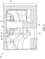
- FIG. 1 is a side view of an engine 100, according to an embodiment of the present disclosure.
- the engine 100 may be any type of engine, such as internal combustion engine run by gasoline, diesel, gaseous fuel, or a combination thereof.
- the engine 100 may be used as a source of power for any machine (not shown), such as, on-highway trucks or vehicles, off-highway trucks or machines, earth moving equipment, pumps, stationary equipment, generators, and the like. Accordingly, the engine 100 may also be used to power machines or devices used in construction, transportation, power generation, aerospace applications, locomotive applications, marine applications, and other engine powered applications.
- the engine 100 is illustrated as a V-Type internal combustion engine 100, having a plurality of cylinder members 108.
- various embodiments and aspects of the present disclosure may be suitably applicable to any type of engine 100 having a single cylinder or multiple cylinder members in any other alternative configurations, such as in-line, radial and the like.
- the engine 100 includes a cylinder block 102 having the cylinder members 108, one of which is labeled via reference numeral 108. It may be apparent to a person ordinarily skilled in the art that certain components of the engine 100, such as camshafts, fuel injectors, valves, etc., are omitted from FIG. 1 .
- Each of the cylinder members 108 includes a piston 110 slidably received therein.
- the engine 100 also includes a connecting rod 114 having a first end 116 and a second end 118. The first end 116 is coupled to a free end of the piston 110.
- the engine 100 also includes a crank case 122 coupled to the cylinder block 102.
- the crank case 122 may be configured to rotatably support a crankshaft 124.
- the crankshaft 124 is coupled to the second end 118 of the connecting rod 114.
- the crankshaft 124 includes crankpins (not shown) configured to couple each of the connecting rods 114 to the crankshaft 124. With such an implementation, a rotational movement of the crankshaft 124 causes a sliding movement of one or more of the pistons 110 inside the corresponding cylinder members 108.
- the crankshaft 124 may include at least one counterweight 128 located adjacent to the second end 118 of the connecting rod 114.
- the counterweights 128 may be configured to rotate along with the crankshaft 124.
- the crankshaft 124 includes multiple bearing journals that are aligned longitudinally along the crankshaft 124.
- Each of the pairs of counterweights 128 may be secured to the crankshaft 124 on each side of the bearing journals.
- Each of the counterweights 128 has a center of gravity at an offset from an axis of rotation of the crankshaft 124.
- the counterweights 128 may be configured to counteract unbalanced forces acting during operation of the engine 100.
- the connecting rods 114 for the corresponding pair of cylinder members 108 on both the cylinder banks may be coupled between the two counterweights 128.
- the engine 100 may also include an oil pan 130 configured to store the lubricating fluid therein.
- the lubricating fluid may be oil.
- the oil pan 130 may be disposed below the crankshaft 124.
- the engine 100 may define one or more fluid passages configured to allow a passage of a lubricating oil therethrough.
- the fluid passage may be configured to receive a lubricating oil therethrough and allow it to reach bearing components or other moving components, such as the pistons 110, a camshaft, the crankshaft 124 and the like.
- the fluid passages may be configured to communicate with the bearing components and other engine moving components in such a manner to communicate the fluid, for example, lubrication oil from the oil pan 130.
- the oil pan 130 collects the lubricating fluid necessary for lubricating engine moving components.
- the lubricating fluid in the oil pan 130 may be pumped and allowed to pass through the fluid passages. It should be understood that there may be any number of the fluid passages that are formed at least partly in various portions of the engine 100, such as, the cylinder block 102, the cylinder head and the like.
- the engine 100 includes a guide member 134 configured for guiding lubricating fluid in the engine 100, according to various embodiments of the present disclosure.
- the guide member 134 is coupled to an outer wall 106 of the cylinder member 108 defining an axis MM' (shown in FIG. 3 ).
- the guide member 134 may be coupled to a bottom wall 107 of the cylinder member 108. Additionally or optionally, the guide member 134 may be coupled indirectly to the cylinder member 108 by way of coupling to the crank case 122.
- the guide member 134 may be coupled to the cylinder member 108 using fasteners, such as, but not limited to, bolts, screws and the like. Additionally or optionally, various adhesives may also be used to couple the guide members 134 with the cylinder member 108.
- the guide member 134 is disposed outside and on one side of the cylinder member 108.
- the guide member 134 is shown to extend from the outer wall 106 of the cylinder member 108. Further, a length of the guide member 134 may be chosen to avoid contact with the counterweights 128 and the crankshaft 124. In an example, multiple guide members 134 may be disposed on other sides of the cylinder member 108.
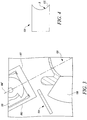
- the guide member 134 according to an embodiment is illustrated.
- the guide member 134 has a planar shape coupled to the outer wall 106 of the cylinder member 108. Further, an end 135 of the guide member 134 may be configured to be attached to the cylinder member 108. Accordingly, the end 135 may have an arc shape with a radius of curvature 'B' that is substantially greater than a radius of curvature (not shown) of the cylinder member 108.
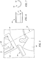
- the guide member 134 according to another embodiment is illustrated. As shown, the guide member 134 has a boat configuration.
- the guide member 134 includes a first portion 142 and a second portion 144 extending from the first portion 142. Further, the first portion 142 may be coupled to the cylinder member 108. The second portion 144 is angularly inclined with respect the first portion 142. The second portion 144 may be inclined at a suitable angle with the first portion 142 so as to guide the lubricant around the counterweight.
- first portion 142 and the second portion 144 may be separate from each other and may be coupled each other to form the guide member 134 using methods such as, but not limited to, fasteners, adhesives and the like.
- first portion 142 and the second portion 144 may be integral to each other to form a unitary construction.
- the first portion 142 may be the guide member 134 having a curvilinear shape
- the second portion 144 may be an extension member coupled to the first portion 142.
- the second portion 144 may also be curvilinear so as to form a rail or drain pipe configuration.
- at least one of the first portion 142 and the second portion 144 may have a planar shape.
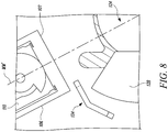
- the guide member 134 is illustrated. As shown, the guide member 134 is disposed below the cylinder member 108. Further, the guide member 134 may be indirectly coupled to the cylinder member 108 by coupling to the crank case 122. As shown, the guide member 134 has a curvilinear shape. Further, the axis of curvature (not shown) of the guide member 134 is substantially perpendicular to the axis MM' of the cylinder member 108. With such a configuration, spilling of the lubricant from sides of the cylinder member 108 onto the counterweights 128 may be avoided.
- An outer surface (not shown) of the guide member 134 may be configured to at least partly direct the lubricating fluid away from an adjacent counterweight 128 of the crankshaft 124 of the engine 100.
- at least a portion of the guide member 134 may be parallel to the adjacent counterweight 128 (best shown in FIG. 1 ). Accordingly, at least a portion of the guide member 134 that is extending from the cylinder member 108 may act as a ramp over the adjacent counterweight 128 to direct the lubricating fluid away from the adjacent counterweight 128.
- the outer surface of the guide member 134 may also be configured to direct the lubricating fluid from the cylinder member 108 into the oil pan 130 of the engine 100.
- the guide member 134 may embody any other shapes based on other parameters, such as tolerances between different components of the engine 100 and the like.
- the guide member 134 may be designed to conform to the dimensions and shape of the corresponding counterweights 128.
- a shape of the corresponding counterweights 128 and/or other components may be modified so as to accommodate the guide member 134.
- multiple guide members 134 may be coupled to the cylinder member 108. Further, the guide members 134 may be disposed so as to allow general movement of other components of the engine 100.
- the guide member 134 is made of one of a sheet metal. In another embodiment, the guide member 134 is made of plastic. In various other embodiments, the guide member 134 may be made of any other light weight materials including, but not limited to, polymers, composites and the like. For example, the guide member 134 may be implemented as a coating on the cylinder member 108.
- the present disclosure relates to the guide member 134 for guiding the lubricating fluid.
- the guide member 134 is coupled to the the cylinder member 108 and is disposed outside the cylinder member 108. Further, the guide member 134 may be configured to direct a flow of the lubricating fluid from the corresponding cylinder member 108 away from the adjacent counterweight 128. With such an implementation in all the cylinder members 108 of the engine 100, the counterweights 128 of the crankshaft 124 may be shielded from contacting with the lubricating fluid falling from the cylinder member 108.
- the guide member 134 may be made of light weight materials such as, plastic, sheet metal, polymers and the like. Additionally, the guide member 134 may be implemented on the existing engines with little or no modification to other components of the engine 100. Moreover, dimensions and a shape of the guide member 134 may be customized to suit different applications.
Landscapes
- Engineering & Computer Science (AREA)
- Mechanical Engineering (AREA)
- General Engineering & Computer Science (AREA)
- Chemical & Material Sciences (AREA)
- Combustion & Propulsion (AREA)
- Shafts, Cranks, Connecting Bars, And Related Bearings (AREA)
- Cylinder Crankcases Of Internal Combustion Engines (AREA)
- Lubrication Of Internal Combustion Engines (AREA)
- Lubrication Details And Ventilation Of Internal Combustion Engines (AREA)
Claims (7)
- Motor (100), umfassend:ein Zylinderelement (108);einen in dem Zylinderelement (108) beweglich angeordneten Kolben (110);eine Kurbelwelle (124), die mit dem Kolben (110) wirkverbunden ist, wobei die Kurbelwelle (124) mindestens ein Gegengewicht (128) aufweist, das sich angrenzend an das Zylinderelement (108) befindet; undein Führungselement (134), das mit dem Zylinderelement (108) gekoppelt ist und außerhalb des Zylinderelements (108) angeordnet ist, wobei das Führungselement (134) einen ersten Abschnitt (142), der mit dem Zylinderelement (108) gekoppelt ist, und einen zweiten Abschnitt (144), der sich winklig von dem ersten Abschnitt (142) erstreckt, umfasst, um Schmiermittel um das Gegengewicht (128) herum zu führen und mindestens teilweise eine Strömung der Schmierflüssigkeit von dem an das Zylinderelement (108) angrenzenden Gegengewicht (128) wegzulenken.
- Motor (100) nach Anspruch 1, wobei das Führungselement (134) aus einem von einem Blech und einem Kunststoff hergestellt ist.
- Motor (100) nach Anspruch 1 oder 2, wobei das Führungselement (134) eine kurvenförmige Form aufweist.
- Motor (100) nach Anspruch 1 oder 2, wobei das Führungselement (134) eine ebene Konfiguration aufweist.
- Motor (100) nach einem der vorhergehenden Ansprüche, wobei das Führungselement (134) mit einem von einer Außenwand (106) des Zylinderelements (108) und einer Bodenwand (107) des Zylinderelements (108) gekoppelt ist.
- Motor (100) nach einem der vorhergehenden Ansprüche, wobei das Führungselement (134) mit dem Zylinderelement (108) unter Verwendung mindestens eines von einem Klebstoff und einem Befestigungselement gekoppelt ist.
- Maschine, umfassend den Motor (100) nach einem der Ansprüche 1 bis 6.
Priority Applications (2)
| Application Number | Priority Date | Filing Date | Title |
|---|---|---|---|
| EP15002358.8A EP3128162B1 (de) | 2015-08-07 | 2015-08-07 | Führungselement zum führen schmierflüssigkeit in einem motor |
| CN201610632996.7A CN106437931A (zh) | 2015-08-07 | 2016-08-04 | 用于导引发动机中的润滑流体的导引构件 |
Applications Claiming Priority (1)
| Application Number | Priority Date | Filing Date | Title |
|---|---|---|---|
| EP15002358.8A EP3128162B1 (de) | 2015-08-07 | 2015-08-07 | Führungselement zum führen schmierflüssigkeit in einem motor |
Publications (2)
| Publication Number | Publication Date |
|---|---|
| EP3128162A1 EP3128162A1 (de) | 2017-02-08 |
| EP3128162B1 true EP3128162B1 (de) | 2021-05-12 |
Family
ID=53835856
Family Applications (1)
| Application Number | Title | Priority Date | Filing Date |
|---|---|---|---|
| EP15002358.8A Active EP3128162B1 (de) | 2015-08-07 | 2015-08-07 | Führungselement zum führen schmierflüssigkeit in einem motor |
Country Status (2)
| Country | Link |
|---|---|
| EP (1) | EP3128162B1 (de) |
| CN (1) | CN106437931A (de) |
Families Citing this family (1)
| Publication number | Priority date | Publication date | Assignee | Title |
|---|---|---|---|---|
| RU199021U1 (ru) * | 2020-03-11 | 2020-08-07 | Федеральное государственное бюджетное образовательное учреждение высшего образования «Брянский государственный технический университет» | Маслозащитное устройство цилиндропоршневой группы двигателя внутреннего сгорания |
Family Cites Families (8)
| Publication number | Priority date | Publication date | Assignee | Title |
|---|---|---|---|---|
| JPS57134343U (de) * | 1981-02-16 | 1982-08-21 | ||
| JPS6334315U (de) * | 1986-08-22 | 1988-03-05 | ||
| JPH05214918A (ja) * | 1992-02-04 | 1993-08-24 | Mitsubishi Heavy Ind Ltd | 2サイクルユニフロー掃気機関の潤滑油消費量低減装置 |
| FR2750474B1 (fr) * | 1996-06-28 | 1998-07-31 | Renault | Carter cylindres pour moteur a combustion interne |
| US7617810B1 (en) | 2007-12-03 | 2009-11-17 | Brunswick Corporation | Counterweight shaft construction which reduces lubricant aeration |
| US8245685B2 (en) * | 2009-06-26 | 2012-08-21 | Ford Global Technologies | Lubrication and sealing system for internal combustion engine |
| DE102013002233A1 (de) * | 2013-02-11 | 2014-08-14 | Man Diesel & Turbo Se | Brennkraftmaschine und Abschirmeinrichtung für eine Zylinderlaufbuchse einer Brennkraftmaschine |
| JP6056788B2 (ja) * | 2013-10-22 | 2017-01-11 | アイシン精機株式会社 | ブローバイガス還流装置 |
-
2015
- 2015-08-07 EP EP15002358.8A patent/EP3128162B1/de active Active
-
2016
- 2016-08-04 CN CN201610632996.7A patent/CN106437931A/zh active Pending
Non-Patent Citations (1)
| Title |
|---|
| None * |
Also Published As
| Publication number | Publication date |
|---|---|
| EP3128162A1 (de) | 2017-02-08 |
| CN106437931A (zh) | 2017-02-22 |
Similar Documents
| Publication | Publication Date | Title |
|---|---|---|
| CN106050386B (zh) | 用于活塞冷却的系统 | |
| CN102667198B (zh) | 用于车辆内燃机的轴瓦片 | |
| US5152373A (en) | Crankshaft lubricating system | |
| US8757028B2 (en) | Crankshaft for a two-stroke engine | |
| EP3091251A1 (de) | Oszillierende kolbenpumpe, kreisförmiger gleitblockmechanismus für körper und kurbel, kreisförmiger gleitblock, lagersitz, kurbelgehäuseoberteilabdeckung und kolbensitz | |
| US8689762B2 (en) | Cylinder head rocker arm stand repair and process | |
| EP3171044B1 (de) | Kurbelwelle für hubkolbenmotor und konstruktionsverfahren für besagte kurbelwelle | |
| EP3171045B1 (de) | Kurbelwelle für hubkolbenmotor | |
| US20190249711A1 (en) | Main bearing for crankshaft of internal combustion engine | |
| EP3128162B1 (de) | Führungselement zum führen schmierflüssigkeit in einem motor | |
| US20140261281A1 (en) | Dry Sump Scavenge Pump System With Balance Shaft Capability For Application To Flat Plane V8 Engines | |
| US9677600B2 (en) | Connecting rod system for an engine | |
| EP3106652A1 (de) | Verschlusselement für ein kurbelgehäuse eines motors | |
| JP4397263B2 (ja) | クランク軸を備える機械 | |
| Vellandi et al. | Design and Development of an Ultra-Low Friction and High Power-Density Diesel for the Indian Market | |
| GB2541212A (en) | Cover assembly for connecting rod of an engine | |
| EP2407658A2 (de) | Mehrzylindermotor | |
| JP2015064009A (ja) | 内燃機関のクランクシャフトの軸受構造 | |
| US8251038B2 (en) | Cylinder head rocker arm stand repair insert | |
| US10247226B2 (en) | Crankshaft for reciprocating engine | |
| JPH09209731A (ja) | 内燃機関の潤滑装置 | |
| JP6374800B2 (ja) | エンジン | |
| GB2507976A (en) | Crankcase engine oil shield | |
| EP1848895A2 (de) | Lageranordnung | |
| WO2008120239A1 (en) | A novel inline two cylinder multi point fuel injection four-stroke reciprocating piston internal combustion spark ignition engine |
Legal Events
| Date | Code | Title | Description |
|---|---|---|---|
| PUAI | Public reference made under article 153(3) epc to a published international application that has entered the european phase |
Free format text: ORIGINAL CODE: 0009012 |
|
| STAA | Information on the status of an ep patent application or granted ep patent |
Free format text: STATUS: THE APPLICATION HAS BEEN PUBLISHED |
|
| AK | Designated contracting states |
Kind code of ref document: A1 Designated state(s): AL AT BE BG CH CY CZ DE DK EE ES FI FR GB GR HR HU IE IS IT LI LT LU LV MC MK MT NL NO PL PT RO RS SE SI SK SM TR |
|
| AX | Request for extension of the european patent |
Extension state: BA ME |
|
| STAA | Information on the status of an ep patent application or granted ep patent |
Free format text: STATUS: REQUEST FOR EXAMINATION WAS MADE |
|
| 17P | Request for examination filed |
Effective date: 20170808 |
|
| RBV | Designated contracting states (corrected) |
Designated state(s): AL AT BE BG CH CY CZ DE DK EE ES FI FR GB GR HR HU IE IS IT LI LT LU LV MC MK MT NL NO PL PT RO RS SE SI SK SM TR |
|
| STAA | Information on the status of an ep patent application or granted ep patent |
Free format text: STATUS: EXAMINATION IS IN PROGRESS |
|
| 17Q | First examination report despatched |
Effective date: 20200128 |
|
| GRAP | Despatch of communication of intention to grant a patent |
Free format text: ORIGINAL CODE: EPIDOSNIGR1 |
|
| STAA | Information on the status of an ep patent application or granted ep patent |
Free format text: STATUS: GRANT OF PATENT IS INTENDED |
|
| RIC1 | Information provided on ipc code assigned before grant |
Ipc: F01M 11/00 20060101ALN20201106BHEP Ipc: F01M 1/08 20060101ALN20201106BHEP Ipc: F02F 1/20 20060101AFI20201106BHEP |
|
| INTG | Intention to grant announced |
Effective date: 20201203 |
|
| RIC1 | Information provided on ipc code assigned before grant |
Ipc: F02F 1/20 20060101AFI20201120BHEP Ipc: F01M 1/08 20060101ALN20201120BHEP Ipc: F01M 11/00 20060101ALN20201120BHEP |
|
| GRAS | Grant fee paid |
Free format text: ORIGINAL CODE: EPIDOSNIGR3 |
|
| GRAA | (expected) grant |
Free format text: ORIGINAL CODE: 0009210 |
|
| STAA | Information on the status of an ep patent application or granted ep patent |
Free format text: STATUS: THE PATENT HAS BEEN GRANTED |
|
| AK | Designated contracting states |
Kind code of ref document: B1 Designated state(s): AL AT BE BG CH CY CZ DE DK EE ES FI FR GB GR HR HU IE IS IT LI LT LU LV MC MK MT NL NO PL PT RO RS SE SI SK SM TR |
|
| REG | Reference to a national code |
Ref country code: GB Ref legal event code: FG4D |
|
| REG | Reference to a national code |
Ref country code: CH Ref legal event code: EP |
|
| REG | Reference to a national code |
Ref country code: DE Ref legal event code: R096 Ref document number: 602015069174 Country of ref document: DE |
|
| REG | Reference to a national code |
Ref country code: IE Ref legal event code: FG4D |
|
| REG | Reference to a national code |
Ref country code: AT Ref legal event code: REF Ref document number: 1392327 Country of ref document: AT Kind code of ref document: T Effective date: 20210615 |
|
| REG | Reference to a national code |
Ref country code: LT Ref legal event code: MG9D |
|
| REG | Reference to a national code |
Ref country code: AT Ref legal event code: MK05 Ref document number: 1392327 Country of ref document: AT Kind code of ref document: T Effective date: 20210512 |
|
| REG | Reference to a national code |
Ref country code: NL Ref legal event code: MP Effective date: 20210512 |
|
| PG25 | Lapsed in a contracting state [announced via postgrant information from national office to epo] |
Ref country code: HR Free format text: LAPSE BECAUSE OF FAILURE TO SUBMIT A TRANSLATION OF THE DESCRIPTION OR TO PAY THE FEE WITHIN THE PRESCRIBED TIME-LIMIT Effective date: 20210512 Ref country code: FI Free format text: LAPSE BECAUSE OF FAILURE TO SUBMIT A TRANSLATION OF THE DESCRIPTION OR TO PAY THE FEE WITHIN THE PRESCRIBED TIME-LIMIT Effective date: 20210512 Ref country code: LT Free format text: LAPSE BECAUSE OF FAILURE TO SUBMIT A TRANSLATION OF THE DESCRIPTION OR TO PAY THE FEE WITHIN THE PRESCRIBED TIME-LIMIT Effective date: 20210512 Ref country code: AT Free format text: LAPSE BECAUSE OF FAILURE TO SUBMIT A TRANSLATION OF THE DESCRIPTION OR TO PAY THE FEE WITHIN THE PRESCRIBED TIME-LIMIT Effective date: 20210512 Ref country code: BG Free format text: LAPSE BECAUSE OF FAILURE TO SUBMIT A TRANSLATION OF THE DESCRIPTION OR TO PAY THE FEE WITHIN THE PRESCRIBED TIME-LIMIT Effective date: 20210812 |
|
| PG25 | Lapsed in a contracting state [announced via postgrant information from national office to epo] |
Ref country code: NO Free format text: LAPSE BECAUSE OF FAILURE TO SUBMIT A TRANSLATION OF THE DESCRIPTION OR TO PAY THE FEE WITHIN THE PRESCRIBED TIME-LIMIT Effective date: 20210812 Ref country code: PL Free format text: LAPSE BECAUSE OF FAILURE TO SUBMIT A TRANSLATION OF THE DESCRIPTION OR TO PAY THE FEE WITHIN THE PRESCRIBED TIME-LIMIT Effective date: 20210512 Ref country code: PT Free format text: LAPSE BECAUSE OF FAILURE TO SUBMIT A TRANSLATION OF THE DESCRIPTION OR TO PAY THE FEE WITHIN THE PRESCRIBED TIME-LIMIT Effective date: 20210913 Ref country code: ES Free format text: LAPSE BECAUSE OF FAILURE TO SUBMIT A TRANSLATION OF THE DESCRIPTION OR TO PAY THE FEE WITHIN THE PRESCRIBED TIME-LIMIT Effective date: 20210512 Ref country code: RS Free format text: LAPSE BECAUSE OF FAILURE TO SUBMIT A TRANSLATION OF THE DESCRIPTION OR TO PAY THE FEE WITHIN THE PRESCRIBED TIME-LIMIT Effective date: 20210512 Ref country code: SE Free format text: LAPSE BECAUSE OF FAILURE TO SUBMIT A TRANSLATION OF THE DESCRIPTION OR TO PAY THE FEE WITHIN THE PRESCRIBED TIME-LIMIT Effective date: 20210512 Ref country code: IS Free format text: LAPSE BECAUSE OF FAILURE TO SUBMIT A TRANSLATION OF THE DESCRIPTION OR TO PAY THE FEE WITHIN THE PRESCRIBED TIME-LIMIT Effective date: 20210912 Ref country code: LV Free format text: LAPSE BECAUSE OF FAILURE TO SUBMIT A TRANSLATION OF THE DESCRIPTION OR TO PAY THE FEE WITHIN THE PRESCRIBED TIME-LIMIT Effective date: 20210512 Ref country code: GR Free format text: LAPSE BECAUSE OF FAILURE TO SUBMIT A TRANSLATION OF THE DESCRIPTION OR TO PAY THE FEE WITHIN THE PRESCRIBED TIME-LIMIT Effective date: 20210813 |
|
| PG25 | Lapsed in a contracting state [announced via postgrant information from national office to epo] |
Ref country code: NL Free format text: LAPSE BECAUSE OF FAILURE TO SUBMIT A TRANSLATION OF THE DESCRIPTION OR TO PAY THE FEE WITHIN THE PRESCRIBED TIME-LIMIT Effective date: 20210512 |
|
| PG25 | Lapsed in a contracting state [announced via postgrant information from national office to epo] |
Ref country code: SM Free format text: LAPSE BECAUSE OF FAILURE TO SUBMIT A TRANSLATION OF THE DESCRIPTION OR TO PAY THE FEE WITHIN THE PRESCRIBED TIME-LIMIT Effective date: 20210512 Ref country code: SK Free format text: LAPSE BECAUSE OF FAILURE TO SUBMIT A TRANSLATION OF THE DESCRIPTION OR TO PAY THE FEE WITHIN THE PRESCRIBED TIME-LIMIT Effective date: 20210512 Ref country code: EE Free format text: LAPSE BECAUSE OF FAILURE TO SUBMIT A TRANSLATION OF THE DESCRIPTION OR TO PAY THE FEE WITHIN THE PRESCRIBED TIME-LIMIT Effective date: 20210512 Ref country code: DK Free format text: LAPSE BECAUSE OF FAILURE TO SUBMIT A TRANSLATION OF THE DESCRIPTION OR TO PAY THE FEE WITHIN THE PRESCRIBED TIME-LIMIT Effective date: 20210512 Ref country code: CZ Free format text: LAPSE BECAUSE OF FAILURE TO SUBMIT A TRANSLATION OF THE DESCRIPTION OR TO PAY THE FEE WITHIN THE PRESCRIBED TIME-LIMIT Effective date: 20210512 Ref country code: RO Free format text: LAPSE BECAUSE OF FAILURE TO SUBMIT A TRANSLATION OF THE DESCRIPTION OR TO PAY THE FEE WITHIN THE PRESCRIBED TIME-LIMIT Effective date: 20210512 |
|
| REG | Reference to a national code |
Ref country code: DE Ref legal event code: R097 Ref document number: 602015069174 Country of ref document: DE |
|
| PLBE | No opposition filed within time limit |
Free format text: ORIGINAL CODE: 0009261 |
|
| STAA | Information on the status of an ep patent application or granted ep patent |
Free format text: STATUS: NO OPPOSITION FILED WITHIN TIME LIMIT |
|
| REG | Reference to a national code |
Ref country code: CH Ref legal event code: PL |
|
| PG25 | Lapsed in a contracting state [announced via postgrant information from national office to epo] |
Ref country code: MC Free format text: LAPSE BECAUSE OF FAILURE TO SUBMIT A TRANSLATION OF THE DESCRIPTION OR TO PAY THE FEE WITHIN THE PRESCRIBED TIME-LIMIT Effective date: 20210512 |
|
| 26N | No opposition filed |
Effective date: 20220215 |
|
| REG | Reference to a national code |
Ref country code: BE Ref legal event code: MM Effective date: 20210831 |
|
| GBPC | Gb: european patent ceased through non-payment of renewal fee |
Effective date: 20210812 |
|
| PG25 | Lapsed in a contracting state [announced via postgrant information from national office to epo] |
Ref country code: LI Free format text: LAPSE BECAUSE OF NON-PAYMENT OF DUE FEES Effective date: 20210831 Ref country code: CH Free format text: LAPSE BECAUSE OF NON-PAYMENT OF DUE FEES Effective date: 20210831 |
|
| PG25 | Lapsed in a contracting state [announced via postgrant information from national office to epo] |
Ref country code: IS Free format text: LAPSE BECAUSE OF FAILURE TO SUBMIT A TRANSLATION OF THE DESCRIPTION OR TO PAY THE FEE WITHIN THE PRESCRIBED TIME-LIMIT Effective date: 20210912 Ref country code: LU Free format text: LAPSE BECAUSE OF NON-PAYMENT OF DUE FEES Effective date: 20210807 Ref country code: AL Free format text: LAPSE BECAUSE OF FAILURE TO SUBMIT A TRANSLATION OF THE DESCRIPTION OR TO PAY THE FEE WITHIN THE PRESCRIBED TIME-LIMIT Effective date: 20210512 |
|
| PG25 | Lapsed in a contracting state [announced via postgrant information from national office to epo] |
Ref country code: IT Free format text: LAPSE BECAUSE OF FAILURE TO SUBMIT A TRANSLATION OF THE DESCRIPTION OR TO PAY THE FEE WITHIN THE PRESCRIBED TIME-LIMIT Effective date: 20210512 Ref country code: IE Free format text: LAPSE BECAUSE OF NON-PAYMENT OF DUE FEES Effective date: 20210807 Ref country code: GB Free format text: LAPSE BECAUSE OF NON-PAYMENT OF DUE FEES Effective date: 20210812 Ref country code: FR Free format text: LAPSE BECAUSE OF NON-PAYMENT OF DUE FEES Effective date: 20210831 Ref country code: BE Free format text: LAPSE BECAUSE OF NON-PAYMENT OF DUE FEES Effective date: 20210831 |
|
| PG25 | Lapsed in a contracting state [announced via postgrant information from national office to epo] |
Ref country code: HU Free format text: LAPSE BECAUSE OF FAILURE TO SUBMIT A TRANSLATION OF THE DESCRIPTION OR TO PAY THE FEE WITHIN THE PRESCRIBED TIME-LIMIT; INVALID AB INITIO Effective date: 20150807 |
|
| P01 | Opt-out of the competence of the unified patent court (upc) registered |
Effective date: 20230517 |
|
| PG25 | Lapsed in a contracting state [announced via postgrant information from national office to epo] |
Ref country code: CY Free format text: LAPSE BECAUSE OF FAILURE TO SUBMIT A TRANSLATION OF THE DESCRIPTION OR TO PAY THE FEE WITHIN THE PRESCRIBED TIME-LIMIT Effective date: 20210512 |
|
| PG25 | Lapsed in a contracting state [announced via postgrant information from national office to epo] |
Ref country code: MK Free format text: LAPSE BECAUSE OF FAILURE TO SUBMIT A TRANSLATION OF THE DESCRIPTION OR TO PAY THE FEE WITHIN THE PRESCRIBED TIME-LIMIT Effective date: 20210512 |
|
| PG25 | Lapsed in a contracting state [announced via postgrant information from national office to epo] |
Ref country code: MT Free format text: LAPSE BECAUSE OF FAILURE TO SUBMIT A TRANSLATION OF THE DESCRIPTION OR TO PAY THE FEE WITHIN THE PRESCRIBED TIME-LIMIT Effective date: 20210512 |
|
| PGFP | Annual fee paid to national office [announced via postgrant information from national office to epo] |
Ref country code: DE Payment date: 20250724 Year of fee payment: 11 |
|
| PG25 | Lapsed in a contracting state [announced via postgrant information from national office to epo] |
Ref country code: TR Free format text: LAPSE BECAUSE OF FAILURE TO SUBMIT A TRANSLATION OF THE DESCRIPTION OR TO PAY THE FEE WITHIN THE PRESCRIBED TIME-LIMIT Effective date: 20210512 |