EP3128235A1 - Gasbrenner, insbesondere für eine kochplatte für haushaltszwecke - Google Patents
Gasbrenner, insbesondere für eine kochplatte für haushaltszwecke Download PDFInfo
- Publication number
- EP3128235A1 EP3128235A1 EP15179560.6A EP15179560A EP3128235A1 EP 3128235 A1 EP3128235 A1 EP 3128235A1 EP 15179560 A EP15179560 A EP 15179560A EP 3128235 A1 EP3128235 A1 EP 3128235A1
- Authority
- EP
- European Patent Office
- Prior art keywords
- burner
- gas
- base
- sheet
- air
- Prior art date
- Legal status (The legal status is an assumption and is not a legal conclusion. Google has not performed a legal analysis and makes no representation as to the accuracy of the status listed.)
- Withdrawn
Links
- 238000010411 cooking Methods 0.000 title claims abstract description 57
- 239000000203 mixture Substances 0.000 claims abstract description 16
- 239000002184 metal Substances 0.000 claims abstract description 15
- 229910052751 metal Inorganic materials 0.000 claims abstract description 15
- 229910001092 metal group alloy Inorganic materials 0.000 claims abstract description 7
- 238000011144 upstream manufacturing Methods 0.000 claims description 4
- 230000008878 coupling Effects 0.000 claims description 2
- 238000010168 coupling process Methods 0.000 claims description 2
- 238000005859 coupling reaction Methods 0.000 claims description 2
- 238000007789 sealing Methods 0.000 claims description 2
- 239000007789 gas Substances 0.000 description 53
- 238000002485 combustion reaction Methods 0.000 description 6
- 238000013021 overheating Methods 0.000 description 6
- 239000000463 material Substances 0.000 description 4
- 230000000694 effects Effects 0.000 description 3
- 238000004519 manufacturing process Methods 0.000 description 3
- 235000013305 food Nutrition 0.000 description 2
- 229910000838 Al alloy Inorganic materials 0.000 description 1
- 229910001369 Brass Inorganic materials 0.000 description 1
- 229910001018 Cast iron Inorganic materials 0.000 description 1
- 229910000831 Steel Inorganic materials 0.000 description 1
- 238000004026 adhesive bonding Methods 0.000 description 1
- 229910045601 alloy Inorganic materials 0.000 description 1
- 239000000956 alloy Substances 0.000 description 1
- 239000004411 aluminium Substances 0.000 description 1
- 229910052782 aluminium Inorganic materials 0.000 description 1
- XAGFODPZIPBFFR-UHFFFAOYSA-N aluminium Chemical compound [Al] XAGFODPZIPBFFR-UHFFFAOYSA-N 0.000 description 1
- QVGXLLKOCUKJST-UHFFFAOYSA-N atomic oxygen Chemical compound [O] QVGXLLKOCUKJST-UHFFFAOYSA-N 0.000 description 1
- 239000010951 brass Substances 0.000 description 1
- 238000004512 die casting Methods 0.000 description 1
- 239000002737 fuel gas Substances 0.000 description 1
- 238000010438 heat treatment Methods 0.000 description 1
- 238000009434 installation Methods 0.000 description 1
- 238000012986 modification Methods 0.000 description 1
- 230000004048 modification Effects 0.000 description 1
- 239000001301 oxygen Substances 0.000 description 1
- 229910052760 oxygen Inorganic materials 0.000 description 1
- 230000002093 peripheral effect Effects 0.000 description 1
- 230000001902 propagating effect Effects 0.000 description 1
- 230000000284 resting effect Effects 0.000 description 1
- 238000000926 separation method Methods 0.000 description 1
- 239000010959 steel Substances 0.000 description 1
- 238000003466 welding Methods 0.000 description 1
Images


Classifications
-
- F—MECHANICAL ENGINEERING; LIGHTING; HEATING; WEAPONS; BLASTING
- F23—COMBUSTION APPARATUS; COMBUSTION PROCESSES
- F23D—BURNERS
- F23D14/00—Burners for combustion of a gas, e.g. of a gas stored under pressure as a liquid
- F23D14/02—Premix gas burners, i.e. in which gaseous fuel is mixed with combustion air upstream of the combustion zone
- F23D14/04—Premix gas burners, i.e. in which gaseous fuel is mixed with combustion air upstream of the combustion zone induction type, e.g. Bunsen burner
- F23D14/06—Premix gas burners, i.e. in which gaseous fuel is mixed with combustion air upstream of the combustion zone induction type, e.g. Bunsen burner with radial outlets at the burner head
- F23D14/065—Premix gas burners, i.e. in which gaseous fuel is mixed with combustion air upstream of the combustion zone induction type, e.g. Bunsen burner with radial outlets at the burner head with injector axis inclined to the burner head axis
-
- F—MECHANICAL ENGINEERING; LIGHTING; HEATING; WEAPONS; BLASTING
- F23—COMBUSTION APPARATUS; COMBUSTION PROCESSES
- F23D—BURNERS
- F23D14/00—Burners for combustion of a gas, e.g. of a gas stored under pressure as a liquid
- F23D14/02—Premix gas burners, i.e. in which gaseous fuel is mixed with combustion air upstream of the combustion zone
- F23D14/04—Premix gas burners, i.e. in which gaseous fuel is mixed with combustion air upstream of the combustion zone induction type, e.g. Bunsen burner
-
- F—MECHANICAL ENGINEERING; LIGHTING; HEATING; WEAPONS; BLASTING
- F23—COMBUSTION APPARATUS; COMBUSTION PROCESSES
- F23D—BURNERS
- F23D14/00—Burners for combustion of a gas, e.g. of a gas stored under pressure as a liquid
- F23D14/02—Premix gas burners, i.e. in which gaseous fuel is mixed with combustion air upstream of the combustion zone
- F23D14/04—Premix gas burners, i.e. in which gaseous fuel is mixed with combustion air upstream of the combustion zone induction type, e.g. Bunsen burner
- F23D14/08—Premix gas burners, i.e. in which gaseous fuel is mixed with combustion air upstream of the combustion zone induction type, e.g. Bunsen burner with axial outlets at the burner head
- F23D14/085—Premix gas burners, i.e. in which gaseous fuel is mixed with combustion air upstream of the combustion zone induction type, e.g. Bunsen burner with axial outlets at the burner head with injector axis inclined to the burner head axis
-
- F—MECHANICAL ENGINEERING; LIGHTING; HEATING; WEAPONS; BLASTING
- F24—HEATING; RANGES; VENTILATING
- F24C—DOMESTIC STOVES OR RANGES ; DETAILS OF DOMESTIC STOVES OR RANGES, OF GENERAL APPLICATION
- F24C3/00—Stoves or ranges for gaseous fuels
- F24C3/08—Arrangement or mounting of burners
-
- F—MECHANICAL ENGINEERING; LIGHTING; HEATING; WEAPONS; BLASTING
- F23—COMBUSTION APPARATUS; COMBUSTION PROCESSES
- F23D—BURNERS
- F23D2203/00—Gaseous fuel burners
- F23D2203/007—Mixing tubes, air supply regulation
-
- F—MECHANICAL ENGINEERING; LIGHTING; HEATING; WEAPONS; BLASTING
- F23—COMBUSTION APPARATUS; COMBUSTION PROCESSES
- F23D—BURNERS
- F23D2212/00—Burner material specifications
-
- F—MECHANICAL ENGINEERING; LIGHTING; HEATING; WEAPONS; BLASTING
- F23—COMBUSTION APPARATUS; COMBUSTION PROCESSES
- F23D—BURNERS
- F23D2213/00—Burner manufacture specifications
Definitions
- the present invention relates to a gas burner, in particular for a cooking top for household use, according to the preamble of claim 1.
- the present invention also relates to a cooking top comprising said gas burner.
- Such gas burners usually comprise a cup associated with supply means that supply gas to said burner.
- Said supply means may comprise a Venturi effect chamber adapted to receive gas coming from an injector associated with a duct; in particular, said injector, duct and/or Venturi effect chamber may be either vertical, i.e. with their axis parallel to an axis of the burner cup, or horizontal, i.e. with their axis orthogonal to the axis of the burner cup.
- Gas burners currently installed in cooking tops for household use typically comprise a cup and a flame divider (or cap) arranged on the cooking top, and utilize, as primary air to be mixed with gas, the air available above the cooking top.
- the cup is usually made of die-cast aluminium, while the flame divider or cap is usually made of enamelled cast iron (or brass alloy or steel) and acts as a cup closing element.
- Known burners typically propagate a flame known as "crown flame”; a “crown flame” is a flame with a substantially radial direction of propagation, i.e.
- a carpet flame may be a total carpet flame or a perimetric carpet flame, depending on whether it covers a geometric figure (generally a circle) entirely or just the peripheral portion of said geometric figure (generally a circular crown).
- document EP1934532 ensures all the advantages that distinguish a "carpet flame” from a “crown flame”, including optimal gas efficiency.
- the burner components are substantially made by die casting, being typically made of die-cast aluminium alloys; it is clear that this solution is an expensive one, and therefore a cooking top comprising such burners will implement solutions that are not very effective in economical terms.
- the flame divider is so realized as to be positioned flush with the visible surface of the cooking top.
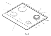
- reference numeral 1 designates as a whole a cooking top according to the present invention, in particular intended for household use and of the built-in type.
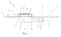
- the cooking top 1 is so shaped as to comprise a substantially flat visible surface 2, on which a plurality of housings 3 are formed or obtained for accommodating at least one gas burner 10, such as the one shown in the sectional view of Fig. 2 and in the exploded perspective view of Fig. 3 .
- the cooking top 1 may also comprise supporting means (not shown) for cooking vessels containing foods to be cooked, which are adapted to ensure an adequate separation distance between the visible surface 2 of the cooking top 1 and said cooking vessels.
- the cooking top 1 may comprise interfacing means (not shown) adapted to, among other things, allow adjusting and/or displaying the operating parameters of each burner 10.
- the interfacing means may comprise a "touch control" interface, or a mechanical interface, for controlling on-off taps.
- the burner 10 adapted for installation in a cooking top 1 comprises a base (designated as a whole by reference numeral 20 in the annexed drawings) equipped with a Venturi element 21 adapted to receive a gas coming from an injector 4, and with a duct 22 for supplying an air-gas mixture to said burner 10.
- Fig. 2 also shows a tube 5 for supplying gas to said injector 4.
- the Venturi element 21 is arranged substantially horizontally, i.e. with its axis substantially orthogonal to an axis A-A (shown in Fig. 2 ) of the burner 10; preferably, also the injector 4 is substantially horizontal.
- the assembly consisting of the Venturi element 21 and the duct 22 is shaped substantially like a pipe, in particular of the type known as "straight pipe". It is however clear that at least one of said elements may be positioned differently, e.g. vertically, i.e. with its axis parallel to said axis A-A of the burner 10.
- said Venturi element 21 allows creating, within the duct 22 and within the entire burner 10, a pressure drop for conveying gas and primary air (i.e. the air-gas mixture) towards the mixing and/or combustion zone of the burner 10.
- Primary air is air mixed with fuel gas inside the gas burner 10
- secondary air is air added to the already formed air-gas mixture in the area outside the cooking top 1 surrounding the gas burner 10, which air is called “secondary air” because it is necessary for providing the additional Oxygen required for a proper combustion.
- the base 20 comprises at least one air intake 23 to allow entry of primary air, in particular said at least one air intake 23 being associated with that part of said base 20 which is adjacent to the injector 4 and upstream of the Venturi element 21, with reference to the gas path.
- said at least one air intake 23 is sufficiently large to ensure an adequate flow of primary air through it.
- a primary air forced circulation system may be associated with said burner 10.
- the gas burner 10 according to the present invention is of the type that takes primary air from below the cooking top 1.
- the base 20 further comprises a seat 24 for housing the injector 4 and/or a terminal portion of said tube 5 for supplying gas to the injector 4, in particular said seat 24 being positioned upstream of said at least one air intake 23 (with reference to the path of the gas and of the primary air/gas mixture).
- the base 20 comprises at least one bracket 25, 26 for associating at least one ignition spark plug 6 and at least one thermocouple 7 with the burner 10; in particular, said base 20 comprises a first bracket 25 for associating said at least one ignition spark plug 6 with the burner 10, and a second bracket 26 for associating said at least one thermocouple 7 with the burner 10.
- the burner 10 further comprises a burner body 30 associated with the base 20 and comprising a hole 31 for the passage of the air-gas mixture coming from the duct 22 of the base 20.
- the burner 10 comprises a flame divider 40 associated with said burner body 30 and comprising a plurality of apertures 41 to allow the air-gas mixture to exit, in particular said apertures 41 being so realized as to generate a "carpet flame", i.e. a flame (not shown in the drawings) that propagates outwards from the burner 10 in a substantially axial direction with respect to the axis A-A of the burner 10.
- the burner body 30 comprises a pair of first openings 30F
- the flame divider 40 comprises a pair of second openings 40F adapted to allow the passage of said at least one ignition spark plug 6 and at least one thermocouple 7. It is in fact clear that, in an operating condition (in particular a condition in which the burner body 30 and the flame divider 40 of the burner 10 are assembled together), said first openings 30F and second openings 40F are aligned to each other.
- said base 20 is made from sheet, in particular metal or metal-alloy sheet, which is shaped by deep drawing; preferably, said base 20 is made from aluminized sheet metal.
- said base 20 comprises a first half shell 20A and a second half shell 20B made from sheet metal and joined together.
- first half shell 20A and the second half shell 20B may be joined together, in particular, by welding; it is however clear that such components may also be joined together otherwise, e.g. by glueing.
- the burner body 30 is made from sheet, in particular metal or metal-alloy sheet, which is shaped by deep drawing.
- the burner body 30 is preferably made from enamelled sheet metal.
- the flame divider 40 is made from sheet, in particular metal or metal-alloy sheet.
- the flame divider 40 is arranged on the burner body 30, in particular said flame divider 40 resting on the burner body 30.
- the flame divider 40 comprises a side wall 42 that allows the apertures 41 to be kept in a raised position relative to the cooking top 1.
- said side wall 42 has a height H (see Fig. 2 ) in the range of 10 mm to 20 mm, in particular said height H being approximately 15 mm.
- the burner body 30 comprises a flank 32, the height of which is essentially close to the height H of said side wall 42, so that the coupling between the burner body 30 and the flame divider 40 will ensure proper sealing and will prevent the air-gas mixture from escaping sideways; in an operating condition of the burner 10 (i.e. a condition in which the burner body 30 and the flame divider 40 of the burner 10 are assembled together), the flank 32 of the burner body 30 and the side wall 42 of the flame divider 40 are arranged substantially side by side and cooperate to keeping the apertures 41 of the flame divider 40 raised relative to the cooking top 1, in particular at a distance substantially corresponding to or slightly greater than said height H.
- an operating condition of the burner 10 i.e. a condition in which the burner body 30 and the flame divider 40 of the burner 10 are assembled together
- the flank 32 of the burner body 30 and the side wall 42 of the flame divider 40 are arranged substantially side by side and cooperate to keeping the apertures 41 of the flame divider 40 raised relative to the cooking top 1, in particular at a distance
- the burner 10 can ensure optimal gas efficiency thanks to the apertures 41, which provide a "carpet flame”; furthermore, the fact that the base 20 is made from sheet metal (just like the burner body 30 and the flame divider 40) allows reducing the costs incurred for manufacturing the burner 10 and the whole cooking top 1.
- flank 32 of the burner body 30 and of the side wall 42 of the flame divider 40 allows the apertures 41 to be positioned at a certain distance (substantially corresponding to the height H) from the visible surface 2 of the cooking top 1, thus preventing overheating of the area of the cooking top 1 around the burner 10; it is clear that this prevents said cooking top 1 from suffering possible damage, particularly when it is made from glassy materials or the like.
- the burner body 30 and the flame divider 40 advantageously have a substantially axially symmetrical shape, since preferably the axis of the burner body 30 and/or of the flame divider 40 substantially coincides with the axis A-A of the burner 10.
- the flame divider 40 also performs the functions of delimiting at the top the inner environment of the burner 10 and allowing the flame originated by the combustion of the air-gas mixture to come out of the burner 10 through the plurality of apertures 41.
- said flame divider 40 is preferably microperforated, i.e. it comprises a plurality of apertures 41, the diameter of which is substantially the same as the thickness of the metal sheet or smaller.
- the thickness of the microperforated sheet is preferably approx. 1 mm, and the diameter of the apertures 41 of the microperforated sheet is conveniently comprised between 100 ⁇ m and 1 mm.
- the burner 10 according to the present invention is so realized as to turn out to be particularly effective, since it ensures optimal gas efficiency thanks to the apertures 41, which produce a "carpet flame"; in addition, the burner 10 according to the present invention has an economical realization, in that the fact that the base 20 is made from sheet metal (just like the burner body 30 and the flame divider 40) makes for lower costs incurred for manufacturing the burner 10 and the whole cooking top 1.
- flank 32 of the burner body 30 and of the side wall 42 of the flame divider 40 prevents overheating of the area of the cooking top 1 around the burner 10, while also preventing said cooking top 1 from suffering damage, particularly when the latter is made from glassy materials or the like.
- the present invention has disclosed in detail a gas burner and a cooking top particularly suited for use in a household environment. Nevertheless, the present invention may also be conveniently implemented in gas burners and cooking tops intended for different applications, e.g. in the hotel industry.
Landscapes
- Engineering & Computer Science (AREA)
- Chemical & Material Sciences (AREA)
- Combustion & Propulsion (AREA)
- Mechanical Engineering (AREA)
- General Engineering & Computer Science (AREA)
- Gas Burners (AREA)
Priority Applications (2)
| Application Number | Priority Date | Filing Date | Title |
|---|---|---|---|
| EP15179560.6A EP3128235A1 (de) | 2015-08-03 | 2015-08-03 | Gasbrenner, insbesondere für eine kochplatte für haushaltszwecke |
| US15/226,184 US20170038076A1 (en) | 2015-08-03 | 2016-08-02 | Gas burner, in particular for a cooking top for household use |
Applications Claiming Priority (1)
| Application Number | Priority Date | Filing Date | Title |
|---|---|---|---|
| EP15179560.6A EP3128235A1 (de) | 2015-08-03 | 2015-08-03 | Gasbrenner, insbesondere für eine kochplatte für haushaltszwecke |
Publications (1)
| Publication Number | Publication Date |
|---|---|
| EP3128235A1 true EP3128235A1 (de) | 2017-02-08 |
Family
ID=54251915
Family Applications (1)
| Application Number | Title | Priority Date | Filing Date |
|---|---|---|---|
| EP15179560.6A Withdrawn EP3128235A1 (de) | 2015-08-03 | 2015-08-03 | Gasbrenner, insbesondere für eine kochplatte für haushaltszwecke |
Country Status (2)
| Country | Link |
|---|---|
| US (1) | US20170038076A1 (de) |
| EP (1) | EP3128235A1 (de) |
Cited By (1)
| Publication number | Priority date | Publication date | Assignee | Title |
|---|---|---|---|---|
| CN114838354A (zh) * | 2022-05-30 | 2022-08-02 | 杭州老板电器股份有限公司 | 上进风燃烧器及燃气灶 |
Families Citing this family (2)
| Publication number | Priority date | Publication date | Assignee | Title |
|---|---|---|---|---|
| CN108981171B (zh) * | 2018-08-20 | 2019-06-28 | 北京华通兴远供热节能技术有限公司 | 一种燃气锅炉烟气、水蒸气及热量回收装置 |
| WO2023195867A1 (es) * | 2022-04-08 | 2023-10-12 | Espinoza Sanchez Julio Victor | Cocina mejorada |
Citations (7)
| Publication number | Priority date | Publication date | Assignee | Title |
|---|---|---|---|---|
| US3219098A (en) * | 1963-02-28 | 1965-11-23 | Roper Corp Geo D | Burner for gas range |
| US5152276A (en) * | 1990-12-27 | 1992-10-06 | Maytag Corporation | Sealed gas burner assembly |
| FR2714155A1 (fr) * | 1993-12-21 | 1995-06-23 | Sourdillon Sa | Corps métallique pour brûleur à gaz d'appareil de chauffage à rayonnement infra-rouge. |
| EP1934532A1 (de) | 2005-09-30 | 2008-06-25 | Indesit Company S.p.A. | Ein semipermeables element umfassende kochfläche mit gasbrenner |
| US20100326420A1 (en) * | 2007-02-27 | 2010-12-30 | Indesit Company S.P. A. | Cooking top |
| WO2013065018A2 (en) * | 2011-11-03 | 2013-05-10 | Indesit Company S.P.A. | Gas burner, in particular for a cooking appliance |
| FR2999276A1 (fr) * | 2012-12-10 | 2014-06-13 | Applic Gaz Sa | Bruleur a gaz comprenant une tete de bruleur |
-
2015
- 2015-08-03 EP EP15179560.6A patent/EP3128235A1/de not_active Withdrawn
-
2016
- 2016-08-02 US US15/226,184 patent/US20170038076A1/en not_active Abandoned
Patent Citations (7)
| Publication number | Priority date | Publication date | Assignee | Title |
|---|---|---|---|---|
| US3219098A (en) * | 1963-02-28 | 1965-11-23 | Roper Corp Geo D | Burner for gas range |
| US5152276A (en) * | 1990-12-27 | 1992-10-06 | Maytag Corporation | Sealed gas burner assembly |
| FR2714155A1 (fr) * | 1993-12-21 | 1995-06-23 | Sourdillon Sa | Corps métallique pour brûleur à gaz d'appareil de chauffage à rayonnement infra-rouge. |
| EP1934532A1 (de) | 2005-09-30 | 2008-06-25 | Indesit Company S.p.A. | Ein semipermeables element umfassende kochfläche mit gasbrenner |
| US20100326420A1 (en) * | 2007-02-27 | 2010-12-30 | Indesit Company S.P. A. | Cooking top |
| WO2013065018A2 (en) * | 2011-11-03 | 2013-05-10 | Indesit Company S.P.A. | Gas burner, in particular for a cooking appliance |
| FR2999276A1 (fr) * | 2012-12-10 | 2014-06-13 | Applic Gaz Sa | Bruleur a gaz comprenant une tete de bruleur |
Cited By (1)
| Publication number | Priority date | Publication date | Assignee | Title |
|---|---|---|---|---|
| CN114838354A (zh) * | 2022-05-30 | 2022-08-02 | 杭州老板电器股份有限公司 | 上进风燃烧器及燃气灶 |
Also Published As
| Publication number | Publication date |
|---|---|
| US20170038076A1 (en) | 2017-02-09 |
Similar Documents
| Publication | Publication Date | Title |
|---|---|---|
| US11441781B2 (en) | System of gas burners, in particular for a cooking top for household use | |
| EP1934532B1 (de) | Ein semipermeables element umfassende kochfläche mit gasbrenner | |
| US20100279238A1 (en) | Gas burner | |
| US10393386B2 (en) | System of gas burners, in particular for a cooking top for household use | |
| WO2008033238A2 (en) | Improved gas burner | |
| CA2719675C (en) | Burner for cooking appliances | |
| EP2773905B1 (de) | Gasbrenner, insbesondere für eine kochvorrichtung | |
| EP3263986A1 (de) | Hocheffizienter hochleistungsbrenner mit innerer flamme | |
| EP3343104B1 (de) | Verteilter vertikalflammenbrenner | |
| JP7281067B2 (ja) | 多炎孔バーナ | |
| AU2013357097A1 (en) | Gas burner comprising a burner heat | |
| US20170038076A1 (en) | Gas burner, in particular for a cooking top for household use | |
| WO2019202423A1 (en) | A cooktop with extractor hood | |
| TW202022293A (zh) | 瓦斯爐用燃燒器以及瓦斯爐 | |
| US8899223B2 (en) | Hot surface igniter shield for a gaseous fuel appliance | |
| EP3591289B1 (de) | Zweikreisbrenner, gasbrenneranordnung und gasherd | |
| JP2015230144A (ja) | コンロバーナ | |
| KR20070053917A (ko) | 실드 더블 버너 | |
| KR100738697B1 (ko) | 실드 더블 버너 | |
| JP6671233B2 (ja) | コンロバーナー | |
| JP2019158234A (ja) | ガスコンロ | |
| CN218993390U (zh) | 火盖及具有其的燃烧器 | |
| TW202340651A (zh) | 爐灶燃燒器及燃氣灶 | |
| EP4513085B1 (de) | Brenner und kochherd | |
| JP2002333109A (ja) | バーナ及びそれを用いたコンロ |
Legal Events
| Date | Code | Title | Description |
|---|---|---|---|
| PUAI | Public reference made under article 153(3) epc to a published international application that has entered the european phase |
Free format text: ORIGINAL CODE: 0009012 |
|
| AK | Designated contracting states |
Kind code of ref document: A1 Designated state(s): AL AT BE BG CH CY CZ DE DK EE ES FI FR GB GR HR HU IE IS IT LI LT LU LV MC MK MT NL NO PL PT RO RS SE SI SK SM TR |
|
| AX | Request for extension of the european patent |
Extension state: BA ME |
|
| RAP1 | Party data changed (applicant data changed or rights of an application transferred) |
Owner name: WHIRLPOOL EMEA S.P.A |
|
| STAA | Information on the status of an ep patent application or granted ep patent |
Free format text: STATUS: THE APPLICATION IS DEEMED TO BE WITHDRAWN |
|
| 18D | Application deemed to be withdrawn |
Effective date: 20170809 |