EP3128236B1 - System aus gasbrennern, insbesondere für eine kochplatte für haushaltszwecke - Google Patents
System aus gasbrennern, insbesondere für eine kochplatte für haushaltszwecke Download PDFInfo
- Publication number
- EP3128236B1 EP3128236B1 EP15179573.9A EP15179573A EP3128236B1 EP 3128236 B1 EP3128236 B1 EP 3128236B1 EP 15179573 A EP15179573 A EP 15179573A EP 3128236 B1 EP3128236 B1 EP 3128236B1
- Authority
- EP
- European Patent Office
- Prior art keywords
- burners
- burner
- base
- burner body
- air
- Prior art date
- Legal status (The legal status is an assumption and is not a legal conclusion. Google has not performed a legal analysis and makes no representation as to the accuracy of the status listed.)
- Active
Links
Images


Classifications
-
- F—MECHANICAL ENGINEERING; LIGHTING; HEATING; WEAPONS; BLASTING
- F24—HEATING; RANGES; VENTILATING
- F24C—DOMESTIC STOVES OR RANGES ; DETAILS OF DOMESTIC STOVES OR RANGES, OF GENERAL APPLICATION
- F24C3/00—Stoves or ranges for gaseous fuels
- F24C3/08—Arrangement or mounting of burners
-
- F—MECHANICAL ENGINEERING; LIGHTING; HEATING; WEAPONS; BLASTING
- F23—COMBUSTION APPARATUS; COMBUSTION PROCESSES
- F23D—BURNERS
- F23D14/00—Burners for combustion of a gas, e.g. of a gas stored under pressure as a liquid
- F23D14/02—Premix gas burners, i.e. in which gaseous fuel is mixed with combustion air upstream of the combustion zone
- F23D14/04—Premix gas burners, i.e. in which gaseous fuel is mixed with combustion air upstream of the combustion zone induction type, e.g. Bunsen burner
- F23D14/06—Premix gas burners, i.e. in which gaseous fuel is mixed with combustion air upstream of the combustion zone induction type, e.g. Bunsen burner with radial outlets at the burner head
- F23D14/065—Premix gas burners, i.e. in which gaseous fuel is mixed with combustion air upstream of the combustion zone induction type, e.g. Bunsen burner with radial outlets at the burner head with injector axis inclined to the burner head axis
-
- F—MECHANICAL ENGINEERING; LIGHTING; HEATING; WEAPONS; BLASTING
- F23—COMBUSTION APPARATUS; COMBUSTION PROCESSES
- F23D—BURNERS
- F23D14/00—Burners for combustion of a gas, e.g. of a gas stored under pressure as a liquid
- F23D14/02—Premix gas burners, i.e. in which gaseous fuel is mixed with combustion air upstream of the combustion zone
- F23D14/04—Premix gas burners, i.e. in which gaseous fuel is mixed with combustion air upstream of the combustion zone induction type, e.g. Bunsen burner
- F23D14/08—Premix gas burners, i.e. in which gaseous fuel is mixed with combustion air upstream of the combustion zone induction type, e.g. Bunsen burner with axial outlets at the burner head
- F23D14/085—Premix gas burners, i.e. in which gaseous fuel is mixed with combustion air upstream of the combustion zone induction type, e.g. Bunsen burner with axial outlets at the burner head with injector axis inclined to the burner head axis
-
- F—MECHANICAL ENGINEERING; LIGHTING; HEATING; WEAPONS; BLASTING
- F23—COMBUSTION APPARATUS; COMBUSTION PROCESSES
- F23D—BURNERS
- F23D2203/00—Gaseous fuel burners
- F23D2203/10—Flame diffusing means
- F23D2203/102—Flame diffusing means using perforated plates
-
- F—MECHANICAL ENGINEERING; LIGHTING; HEATING; WEAPONS; BLASTING
- F23—COMBUSTION APPARATUS; COMBUSTION PROCESSES
- F23D—BURNERS
- F23D2213/00—Burner manufacture specifications
-
- F—MECHANICAL ENGINEERING; LIGHTING; HEATING; WEAPONS; BLASTING
- F23—COMBUSTION APPARATUS; COMBUSTION PROCESSES
- F23D—BURNERS
- F23D2900/00—Special features of, or arrangements for burners using fluid fuels or solid fuels suspended in a carrier gas
- F23D2900/14—Special features of gas burners
- F23D2900/14062—Special features of gas burners for cooking ranges having multiple flame rings
Definitions
- the present invention relates to a system of gas burners, in particular for a cooking top for household use, according to the preamble of claim 1.
- the present invention also relates to a cooking top comprising said gas burner.
- Such systems of burners are known as "double-crown", and include gas supply means, said supply means comprising, for example, a pair of gas inlet ducts associated with independent control valves, so that the two burners (i.e. the outer burner and the inner burner) can be used either together or separately in order to achieve good variability and a homogeneous distribution of the heat to be supplied to the cooking containers.
- both concentric burners may be fed by a single gas inlet duct, with an associated tap, which simultaneously feeds the different intake channels that supply the air-gas mixture to the concentric burners.
- Such systems of burners further comprise a cup comprising at least one first chamber for supplying the air-gas mixture to the inner burner and at least one second chamber for supplying said air-gas mixture to the outer burner, said cup being associated with the supply means and with at least one flame divider (or cap).
- the cup and the flame divider may be positioned on the cooking top where the system of burners is installed, and use the air above the cooking top as primary air to be mixed with the gas.
- the cup is usually made of die-cast aluminium, while the flame divider or cap is usually made of enamelled cast iron (or brass alloy or steel) and acts as a cup closing element.
- Known burners typically propagate a flame known as “crown flame”; a “crown flame” is a flame with a substantially radial direction of propagation, i.e. a flame that propagates outwards from the gas burner in a substantially radial direction with respect to the burner axis, and therefore in a direction which is substantially tangential to a visible surface of the cooking top.
- Said “crown flame” when emitted at an insufficient height above the cooking top, may cause low-CO 2 combustion, resulting in the generation of a high level of unburnt products (CO and NOx).
- Systems of burners are also known in the art which comprise a flame divider or cap comprising a plurality of apertures adapted to generate a "carpet flame", i.e. a flame that propagates out of the system of burners in a substantially axial direction with respect to the axis of the system of burners, and therefore in a direction which is substantially orthogonal to a visible surface of the cooking top.
- a "carpet flame” i.e. a flame that propagates out of the system of burners in a substantially axial direction with respect to the axis of the system of burners, and therefore in a direction which is substantially orthogonal to a visible surface of the cooking top.
- a carpet flame may be a total carpet flame or a perimetric carpet flame, depending on whether it covers a geometric figure (generally a circle) entirely or just the peripheral portion of said geometric figure (generally a circular crown).
- a system of gas burners according to the preamble of claim 1 is known from US2007/059657 .
- the flame divider is so realized as to be positioned flush with the visible surface of the cooking top.
- the system of burners it has been noticed that such a realization may cause overheating of that area of the visible surface of the cooking top which is closest to the system of burners; it is clear that this overheating may also cause damages to the cooking top, particularly when the latter is made from glassy materials or the like.
- reference numeral 1 designates as a whole a cooking top according to the present invention, in particular intended for household use and of the embedded type.
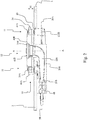
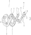
- the cooking top 1 is so shaped as to comprise a substantially flat visible surface 2, on which a plurality of housings 3 are formed for accommodating at least one system of gas burners 10, such as the one shown in the sectional view of Fig. 2 and in the exploded perspective view of Fig. 3 .
- the cooking top 1 may also comprise supporting means (not shown) for cooking vessels containing foods to be cooked, said supporting means being adapted to ensure an adequate separation distance between the visible surface 2 of the cooking top 1 and said cooking vessels.
- the cooking top 1 may comprise interfacing means (not shown) adapted to, among other things, allow adjusting and/or displaying the operating parameters of the system of burners 10 and of other burners (also not shown) associated with the cooking top 1.
- the interfacing means may comprise a "touch control" interface, or a mechanical interface, for controlling on-off taps.
- the system of burners 10 adapted for installation in a cooking top 1 comprises a pair of substantially concentric burners 11, 12, said pair of burners 11, 12 comprising:
- the first base 20A of the outer burner 11 and the second base 20B of the inner burner 12 are made from sheet, in particular metal or metal-alloy sheet, said sheet being shaped by deep drawing.
- said first flame divider 40A and said second flame divider 40B comprise, respectively, a plurality of first apertures 41A and second apertures 41B to allow an air-gas mixture to exit, said first apertures 41A and second apertures 41B being so realized as to extend substantially parallel to an axis A-A of the system of burners 10.
- the particular realization of the first apertures 41A and second apertures 41B can be especially appreciated in a sectional view and when viewed in a direction substantially perpendicular to the axis A-A (as shown in Fig. 2 ) of the system of burners 10.
- first apertures 41A and second apertures 41B are so realized as to generate a flame that propagates outwards from the system of burners 10 in a direction substantially parallel to said axis A-A of the system of burners 10, said first apertures 41A and second apertures 41B being thus so realized as to generate a "carpet flame”.
- the system of burners 10 according to the present invention is therefore realized to be particularly effective and economical.
- the system of burners 10 can ensure optimal gas efficiency thanks to the first apertures 41A and second apertures 41B, which provide a "carpet flame"; furthermore, the fact that the first base 20A and the second base 20B are made from sheet metal allows reducing the costs incurred for manufacturing the system of burners 10 and the whole cooking top 1.
- the first base 20A of the outer burner 11 comprises a first Venturi element 21A adapted to receive gas coming from a first injector 4A and a first duct 122A for supplying an air-gas mixture to said first base 20A and to the outer burner 11.
- Fig. 2 also shows a first tube 5A for supplying gas to said first injector 4A.
- the first base 20A of the outer burner 11 is so realized that said first duct 122A enters a substantially toroidal portion 122B having at least one aperture 122C for the gas flow.
- the second base 20B of the inner burner 12 comprises a second Venturi element 21B adapted to receive gas coming from a second injector 4B and a second duct 122B for supplying an air-gas mixture to said second base 20B and to the inner burner 12.
- Fig. 2 also shows a second tube 5B for supplying gas to said second injector 4B.
- the assembly consisting of the second Venturi element 21B and the second duct 22B is shaped substantially like a pipe, in particular of the type known as "straight pipe".
- the first Venturi element 21A and the second Venturi element 21B are arranged substantially horizontal, i.e. with their axis substantially orthogonal to an axis A-A (shown in Fig. 2 ) of the system of burners 10; preferably, also the first injector 4A and the second injector 4B are arranged substantially horizontal and with their axis substantially orthogonal to said axis A-A.
- the first Venturi element 21A and the second Venturi element 21B allow creating a pressure drop within the first duct 122A and second duct 22B, said pressure drop being used for conveying the gas (enriched with primary air, i.e. the air-gas mixture) towards the combustion area of the system of burners 10.
- Primary air is air mixed with fuel gas inside the system of gas burners 10
- secondary air is air added to the already formed air-gas mixture in the area outside the cooking top 1 surrounding the system of gas burners 10, said “secondary air” being necessary for providing the additional Oxygen required for a proper combustion.
- the first base 20A comprises at least one first air intake 23A to allow entry of primary air, in particular said at least one first air intake 23A being associated with that part of said first base 20A which is adjacent to the first injector 4A and upstream of the first Venturi element 21A, with reference to the gas path.
- the second base 20B comprises at least one second air intake 23B to allow entry of primary air, in particular said at least one second air intake 23B being associated with that part of said second base 20B which is adjacent to the second injector 4B and upstream of the second Venturi element 21B, with reference to the gas path.
- said at least one first air intake 23A and said at least one second air intake 23B are sufficiently large to ensure an adequate flow of primary air through them.
- a primary air forced circulation system (not shown in the annexed drawings) may be associated with said system of burners 10.
- system of gas burners 10 is of the type that takes primary air from below the cooking top 1.
- the first base 20A and the second base 20B preferably comprise, respectively, a first seat 24A and a second seat 24B adapted to house, respectively, the first injector 4A and the second injector 4B and/or a terminal portion of said first tube 5A and second tube 5B, in particular said first seat 24A and second seat 24B being located upstream of said at least one first air intake 23A and second air intake 23B (with reference to the path of the gas and of the primary air/gas mixture).
- the first base 20A comprises a first half body 121A and a second half body 122A made form sheet metal and joined together; moreover, the second base 20B comprises a first half shell 121B and a second half shell 122B made from sheet metal and joined together.
- first half body 121A and the second half body 122A are joined together by welding, just like the first half shell 121B and the second half shell 122B; it is however clear that such components may be joined together otherwise, e.g. by glueing or through the use of fastening means.
- the first base 20A and the second base 20B may then comprise connection means (not shown) for associating at least one ignition spark plug 6 and at least one thermocouple 7 with the system of burners 10; furthermore, said first base 20A and second base 20B may be joined together.
- the annexed drawings also show that the first burner body 30A of the outer burner 11 is coupled to the portion 122B of the first base 20A and comprises at least one opening 31A adapted to be coupled to said at least one aperture 122C of said portion 122B to allow the passage of the gas (in particular, the passage of the primary air-gas mixture).
- the first burner body 30A comprises also a central hole 32A adapted to house the second burner body 30B of the inner burner 12, said second burner body 30B being coupled to the second base 20B and comprising a second hole 32B for the passage of the gas coming from the second duct 22B of the second base 20B.
- the first burner body 30A and the second burner body 30B are substantially shaped like a circular crown, the second burner body 30B being arranged in a substantially concentric manner in the central hole 32A of the first burner body 30A.
- first burner body 30A and the second burner body 30B are made from sheet, in particular metal or metal-alloy sheet, which are shaped by deep drawing.
- said first burner body 30A and second burner body 30B are preferably made from enamelled sheet metal.
- the first burner body 30A and the second burner body 30B are preferably joined together by at least one bridge 33 (visible in Fig. 3 ); in particular, said at least one bridge 33 comprises a first and a second bridge 33 substantially positioned on opposite sides with respect to the second burner body 30B.
- first flame divider 40A is positioned on the first burner body 30A of the outer burner 11 and the second flame divider 40B is positioned on the second burner body 30B of the inner burner 12; preferably, in a top view of the system of burners 10 according to the present invention, the shape and dimensions of said first flame divider 40A and second flame divider 40B almost coincide, respectively, with those of said first burner body 30A and second burner body 30B.
- first flame divider 40A and second flame divider 40B are made from sheet, in particular metal or metal-alloy sheet.
- the first flame divider 40A is preferably made as one piece adapted to be positioned on the first burner body 30A, and the second flame divider 40B is coupled to said first flame divider 40A by means of at least one arm 42; in particular, said at least one arm 42 comprises a pair of arms 42 located on substantially opposite sides with respect to the second flame divider 40B.
- said at least one arm 42 may be so realized as to comprise third apertures 42A, the function of which is to ensure adequate ignition and combustion of the air-gas mixture coming out of the first apertures 41A and second apertures 41B.
- the first flame divider 40A comprises a side wall 43 that allows the apertures 41A, 41B to be kept in a raised position relative to the cooking top 1.
- said side wall 43 has a height H (see Fig. 2 ) in the range of 10 mm to 20 mm, in particular said height H being approximately 15 mm.
- the first burner body 30A comprises a flank 34, the height of which is essentially close to said height H of said side wall 43, so that the coupling between the burner body 30 and the flame divider 40 will ensure proper sealing and will prevent the air-gas mixture from escaping sideways; in an operating condition of the system of burners 10 (i.e. a condition in which the first burner body 30A and the first flame divider 40A of the system of burners 10 are assembled together), the flank 34 of the first burner body 30A and the side wall 43 of the first flame divider 40A are arranged substantially side by side and cooperate to keeping the apertures 41A, 41B raised relative to the cooking top 1, in particular at a distance substantially corresponding to or slightly greater than said height H.
- the particular realization of the side wall 43 of the first flame divider 40A and of the flank 34 of the first burner body 30A allows the first apertures 41A of the first flame divider 40A and the second apertures 41B of the second flame divider 40B to be positioned at a certain distance (substantially corresponding to the height H) from the visible surface 2 of the cooking top 1; this provision prevents overheating of the area of the cooking top 1 around the system of burners 10. It is clear that this prevents said cooking top 1 from suffering possible damage, particularly when it is made from glassy materials or the like.
- first flame divider 40A and the second flame divider 40B provide the functions of delimiting the internal environment of the system of burners 10 at the top and of allowing the flame generated by the combustion of the air-gas mixture to exit the system of burners 10 through the plurality of first apertures 41A and second apertures 41B.
- first flame divider 40A and the second flame divider 40B are preferably microperforated, i.e. they are so realized as to comprise a plurality of first apertures 41A and second apertures 41B, the diameter of which is substantially equal to the thickness of the sheet or smaller than the thickness of the sheet.
- the thickness of the microperforated sheet is preferably approximately 1 mm, and the diameter of the first apertures 41A and second apertures 41B of the microperforated sheet is conveniently comprised between 100 ⁇ m and 1 mm.
- the system of burners 10 is so realized as to comprise a first tube 5A and a second tube 5B associated with independent control valves (not shown), so that the outer burner 11 and the inner burner 12 can be used either jointly or separately. Consequently, in this preferred embodiment the system of burners 10 is of the double-crown, double-control type, and ensures good variability and a homogeneous distribution of the heat to be supplied to a cooking container positioned over said system of burners 10. It is however clear that the system of burners 10 according to the present invention may also be of the double-crown, single-control type, i.e. realized in such a way that the outer burner 11 and the inner burner 12 are fed by a common gas inlet duct associated with a common tap or control valve (not shown).
- the system of burners 10 according to the present invention is so realized as to turn out to be particularly effective, in that it ensures optimal gas efficiency thanks to the first apertures 41A and second apertures 41B, which produce a "carpet flame".
- the system of burners 10 according to the present invention is so realized as to turn out to be particularly economical, in that the fact that the first base 20A and the second base 20B are made from sheet metal allows reducing the costs incurred for manufacturing the system of burners 10 and the whole cooking top 1.
- first burner body 30A, the second burner body 30B, the first flame divider 40A and the second flame divider 40B are preferably made from sheet metal.
- the present description has disclosed in detail a system of gas burners and a cooking top particularly suited for use in a household environment. Nevertheless, the present invention may also be conveniently implemented in systems of gas burners and cooking tops intended for different applications, e.g. in the hotel industry.
Landscapes
- Engineering & Computer Science (AREA)
- Chemical & Material Sciences (AREA)
- Combustion & Propulsion (AREA)
- Mechanical Engineering (AREA)
- General Engineering & Computer Science (AREA)
- Gas Burners (AREA)
Claims (13)
- System von Gasbrennern (10), insbesondere für ein Kochfeld (1) für Haushaltszwecke, umfassend ein Paar von im Wesentlichen konzentrischen Brennern (11, 12), wobei das Paar von Brennern (11, 12) umfasst:- einen Außenbrenner (11), der mit einer ersten Basis (20A), einem ersten Brennerkörper (30A) und einem ersten Flammenteiler (40A) ausgestattet ist;- einen Innenbrenner (12), der mit einer zweiten Basis (20B), einem zweiten Brennerkörper (30B) und einem zweiten Flammenteiler (40B) ausgestattet ist,wobei die erste Basis (20A) des Außenbrenners (11) und die zweite Basis (20B) des Innenbrenners (12) aus Blech, insbesondere Metall- oder Metalllegierungsblech hergestellt sind, das durch Tiefziehen geformt wird,
und wobei die erste Basis (20A) des Außenbrenners (11) ein erstes Venturi-Element (21A), das ausgelegt ist, Gas aufzunehmen, das aus einem ersten Injektor (4A) kommt, und einen ersten Kanal (122A) zum Zuführen einer Luft-Gas-Mischung zu der ersten Basis (20A) und zu dem Außenbrenner (11) umfasst,
dadurch gekennzeichnet, dass
die zweite Basis (20B) des Innenbrenners (12) ein zweites Venturi-Element (21B), das ausgelegt ist, Gas aufzunehmen, das aus einem zweiten Injektor (4B) kommt, und einen zweiten Kanal (122B) zum Zuführen einer Luft-Gas-Mischung zu der zweiten Basis (20B) und zu dem Innenbrenner (12) umfasst,
wobei die erste Basis (20A) einen ersten Halbkörper (121A) und einen zweiten Halbkörper (122A) umfasst, die aus Blech hergestellt und miteinander verbunden sind, wobei die zweite Basis (20B) eine erste Halbschale (121B) und eine zweite Halbschale (122B) umfasst, die aus Blech gefertigt und miteinander verbunden sind. - System von Brennern (10) nach Anspruch 1, dadurch gekennzeichnet, dass der erste Flammenteiler (40A) und der zweite Flammenteiler (40B) jeweils mehrere erste Öffnungen (41A) und zweite Öffnungen (41B) umfassen, um eine Luft-Gas-Mischung entweichen zu lassen, wobei die ersten Öffnungen (41A) und zweiten Öffnungen (41B) derart ausgebildet sind, dass sie sich im Wesentlichen parallel zu einer Achse (A-A) des Brennersystems (10) erstrecken.
- Brennersystem (10) nach Anspruch 1, dadurch gekennzeichnet, dass die erste Basis (20A) des Außenbrenners (11) derart ausgebildet ist, dass der erste Kanal (122A) in einen im Wesentlichen torusförmigen Abschnitt (122B) mit mindestens einer Öffnung (122C) für den Durchlass der Luft-Gas-Mischung eintritt.
- System von Brennern (10) nach Anspruch 1, dadurch gekennzeichnet, dass die aus dem zweiten Venturi-Element (21B) und dem zweiten Kanal (22B) bestehende Anordnung im Wesentlichen wie ein Rohr geformt ist.
- System von Brennern (10) nach einem oder mehreren der vorstehenden Ansprüche 1 bis 4, dadurch gekennzeichnet, dass das erste Venturi-Element (21A) und das zweite Venturi-Element (21B) im Wesentlichen horizontal, d. h. mit ihrer Achse im Wesentlichen senkrecht zu einer Achse (A-A) des Systems von Brennern (10) angeordnet sind.
- System von Brennern (10) nach einem oder mehreren der vorstehenden Ansprüche 1 bis 5, dadurch gekennzeichnet, dass es von der Art ist, die Primärluft von unterhalb des Kochfeldes (1), insbesondere der ersten Basis (20A) und der zweite Basis (20B) aufnimmt, die jeweils mindestens einen ersten Lufteinlass (23A) und mindestens einen zweiten Lufteinlass (23B) umfassen, um den Eintritt von Primärluft zu ermöglichen, die sich stromaufwärts des ersten Venturi-Elements (21A) und des zweiten Venturi-Elements (21B) befinden.
- System von Brennern (10) nach einem oder mehreren der vorstehenden Ansprüche, dadurch gekennzeichnet, dass der erste Brennerkörper (30A) und der zweite Brennerkörper (30B) aus Blech, insbesondere Metall oder Metalllegierungsblech, hergestellt sind, die durch Tiefziehen geformt werden.
- System von Brennern (10) nach einem oder mehreren der vorstehenden Ansprüche 1 und 7, dadurch gekennzeichnet, dass der erste Brennerkörper (30A) und der zweite Brennerkörper (30B) mittels mindestens einer Brücke (33) miteinander verbunden sind.
- System von Brennern (10) nach einem oder mehreren der Ansprüche 1, 7 und 8, dadurch gekennzeichnet, dass der erste Brennerkörper (30A) und der zweite Brennerkörper (30B) im Wesentlichen wie eine Kreiskrone ausgebildet sind, wobei der zweite Brennerkörper (30B) im Wesentlichen konzentrisch in einem zentralen Loch (32A) des ersten Brennerkörpers (30A) angeordnet ist.
- System von Brennern (10) nach einem oder mehreren der vorstehenden Ansprüche, dadurch gekennzeichnet, dass der erste Flammenteiler (40A) und der zweite Flammenteiler (30B) aus Blech, insbesondere Metall oder Metalllegierungsblech, hergestellt sind.
- System von Brennern (10) nach einem oder mehreren der vorstehenden Ansprüche, dadurch gekennzeichnet, dass der erste Flammenteiler (40A) eine Seitenwand (43) umfasst, die es ermöglicht, die Öffnungen (41A, 41B) in einer relativ zum Kochfeld (1) angehobenen Position zu halten, wobei die Seitenwand (43) insbesondere eine Höhe (H) im Bereich von 10 mm bis 20 mm aufweist, wobei die Höhe (H) insbesondere ungefähr 15 mm beträgt.
- System von Brennern (10) nach Anspruch 11, dadurch gekennzeichnet, dass der erste Brennerkörper (30A) eine Flanke (34) umfasst, deren Höhe im Wesentlichen nahe an der Höhe (H) der Seitenwand (43) liegt, so dass die Kopplung zwischen dem Brennerkörper (30) und dem Flammenteiler (40) eine einwandfreie Abdichtung gewährleistet und verhindert, dass die Luft-Gas-Mischung seitlich austritt, wobei die Flanke (34) des ersten Brennerkörpers (30A) und die Seitenwand (43) des ersten Flammenteilers (40A) in einem Betriebszustand des Systems von Brennern (10) im Wesentlichen nebeneinander angeordnet ist.
- Kochfeld, umfassend ein System von Gasbrennern (10) nach einem oder mehreren der vorstehenden Ansprüche 1 bis 12.
Priority Applications (3)
| Application Number | Priority Date | Filing Date | Title |
|---|---|---|---|
| EP15179573.9A EP3128236B1 (de) | 2015-08-03 | 2015-08-03 | System aus gasbrennern, insbesondere für eine kochplatte für haushaltszwecke |
| US15/227,157 US10578308B2 (en) | 2015-08-03 | 2016-08-03 | System of gas burners, in particular for a cooking top for household use |
| US16/748,011 US11441781B2 (en) | 2015-08-03 | 2020-01-21 | System of gas burners, in particular for a cooking top for household use |
Applications Claiming Priority (1)
| Application Number | Priority Date | Filing Date | Title |
|---|---|---|---|
| EP15179573.9A EP3128236B1 (de) | 2015-08-03 | 2015-08-03 | System aus gasbrennern, insbesondere für eine kochplatte für haushaltszwecke |
Publications (2)
| Publication Number | Publication Date |
|---|---|
| EP3128236A1 EP3128236A1 (de) | 2017-02-08 |
| EP3128236B1 true EP3128236B1 (de) | 2020-04-08 |
Family
ID=54251916
Family Applications (1)
| Application Number | Title | Priority Date | Filing Date |
|---|---|---|---|
| EP15179573.9A Active EP3128236B1 (de) | 2015-08-03 | 2015-08-03 | System aus gasbrennern, insbesondere für eine kochplatte für haushaltszwecke |
Country Status (2)
| Country | Link |
|---|---|
| US (2) | US10578308B2 (de) |
| EP (1) | EP3128236B1 (de) |
Families Citing this family (5)
| Publication number | Priority date | Publication date | Assignee | Title |
|---|---|---|---|---|
| CN109681869B (zh) * | 2018-11-20 | 2020-06-23 | 吴江市格瑞福金属制品有限公司 | 一种燃气灶头 |
| EP3980688B1 (de) * | 2019-07-10 | 2024-08-14 | Femas Metal San. Ve Tic. A.S. | Brenneranordnung mit einem venturi-element für gaskochgerät |
| US11473775B2 (en) | 2019-08-08 | 2022-10-18 | Whirlpool Corporation | Cooking appliance having a hob |
| EP4337889A4 (de) * | 2021-05-12 | 2025-07-09 | Liva Gaz Armaturleri Ve Endustriyel Mutfak Aksesuarlari Sanayi Ve Ticaret Ltd Sirketi | Brenner für gasherde |
| US11940148B2 (en) | 2021-10-28 | 2024-03-26 | Electrolux Appliances Aktiebolag | Multi injection dual ring gas burner for domestic gas cooking units |
Family Cites Families (12)
| Publication number | Priority date | Publication date | Assignee | Title |
|---|---|---|---|---|
| US1903032A (en) * | 1932-03-28 | 1933-03-28 | Alderic Fugere | Burner |
| US5152276A (en) * | 1990-12-27 | 1992-10-06 | Maytag Corporation | Sealed gas burner assembly |
| US6132205A (en) * | 2000-01-06 | 2000-10-17 | Harneit; Uwe | Multi-ring sealed gas burner |
| US6923643B2 (en) * | 2003-06-12 | 2005-08-02 | Honeywell International Inc. | Premix burner for warm air furnace |
| US7591008B2 (en) * | 2005-06-30 | 2009-09-15 | Microsoft Corporation | Client authentication using multiple user certificates |
| US20070059657A1 (en) * | 2005-09-15 | 2007-03-15 | Chia-Hsi Yen | Gas burner |
| ITRN20070013A1 (it) * | 2007-02-27 | 2008-08-28 | Indesit Company Spa | Piano cottura. |
| ES2375855B1 (es) * | 2009-01-26 | 2012-10-10 | Butsir S.L | Quemador doble de gas. |
| US8985092B2 (en) * | 2011-10-05 | 2015-03-24 | W.C. Bradley Co. | Cooking grill and burner having V-shaped firebox |
| FR2999276B1 (fr) * | 2012-12-10 | 2014-12-12 | Applic Gaz Sa | Bruleur a gaz comprenant une tete de bruleur |
| US20150107577A1 (en) * | 2013-10-18 | 2015-04-23 | Lg Electronics Inc. | Burner |
| US9951959B2 (en) * | 2013-12-20 | 2018-04-24 | Bsh Home Appliances Corporation | Home appliance with improved burner |
-
2015
- 2015-08-03 EP EP15179573.9A patent/EP3128236B1/de active Active
-
2016
- 2016-08-03 US US15/227,157 patent/US10578308B2/en not_active Expired - Fee Related
-
2020
- 2020-01-21 US US16/748,011 patent/US11441781B2/en active Active
Non-Patent Citations (1)
| Title |
|---|
| None * |
Also Published As
| Publication number | Publication date |
|---|---|
| US11441781B2 (en) | 2022-09-13 |
| US10578308B2 (en) | 2020-03-03 |
| US20200158345A1 (en) | 2020-05-21 |
| EP3128236A1 (de) | 2017-02-08 |
| US20170038078A1 (en) | 2017-02-09 |
Similar Documents
| Publication | Publication Date | Title |
|---|---|---|
| US11441781B2 (en) | System of gas burners, in particular for a cooking top for household use | |
| US9127838B2 (en) | Gas burner for cooking appliances | |
| EP2697567B1 (de) | Gasbrenner für gargeräte | |
| EP0552135B1 (de) | Gaskochherdbrenner mit drei konzentrischen Flammen | |
| US10393386B2 (en) | System of gas burners, in particular for a cooking top for household use | |
| US9416963B2 (en) | Cooking top with improved gas top burner | |
| CA2719675C (en) | Burner for cooking appliances | |
| US20100154776A1 (en) | Cooking range burner head assembly | |
| EP1781989B1 (de) | Gasbrenner mit mehreren flammenringen | |
| EP3263986A1 (de) | Hocheffizienter hochleistungsbrenner mit innerer flamme | |
| US20100186730A1 (en) | Gas burner | |
| TR201906118T4 (tr) | Mutfak ocağı için gaz brülörü. | |
| EP2799771B1 (de) | Gasbrenner, insbesondere für Kochgerät | |
| EP3128235A1 (de) | Gasbrenner, insbesondere für eine kochplatte für haushaltszwecke | |
| US20060147865A1 (en) | Cooking range burner head assembly | |
| US20210172608A1 (en) | A pan support, a gas stove and a method for producing a pan support | |
| US10605462B2 (en) | Main top of a cooktop appliance | |
| JP7132111B2 (ja) | コンロ用バーナ並びにガスコンロ | |
| US8899223B2 (en) | Hot surface igniter shield for a gaseous fuel appliance | |
| EP3591289B1 (de) | Zweikreisbrenner, gasbrenneranordnung und gasherd | |
| JP2006138596A (ja) | ガスコンロ | |
| US20250003584A1 (en) | Gas burner, gas burner arrangement and gas stove | |
| TW202340651A (zh) | 爐灶燃燒器及燃氣灶 | |
| JP2023073167A (ja) | コンロバーナ、およびコンロバーナを搭載した加熱調理器 | |
| HK40092266A (en) | Stove burner and gas stove |
Legal Events
| Date | Code | Title | Description |
|---|---|---|---|
| PUAI | Public reference made under article 153(3) epc to a published international application that has entered the european phase |
Free format text: ORIGINAL CODE: 0009012 |
|
| STAA | Information on the status of an ep patent application or granted ep patent |
Free format text: STATUS: THE APPLICATION HAS BEEN PUBLISHED |
|
| AK | Designated contracting states |
Kind code of ref document: A1 Designated state(s): AL AT BE BG CH CY CZ DE DK EE ES FI FR GB GR HR HU IE IS IT LI LT LU LV MC MK MT NL NO PL PT RO RS SE SI SK SM TR |
|
| AX | Request for extension of the european patent |
Extension state: BA ME |
|
| RAP1 | Party data changed (applicant data changed or rights of an application transferred) |
Owner name: WHIRLPOOL EMEA S.P.A |
|
| STAA | Information on the status of an ep patent application or granted ep patent |
Free format text: STATUS: REQUEST FOR EXAMINATION WAS MADE |
|
| 17P | Request for examination filed |
Effective date: 20170807 |
|
| RBV | Designated contracting states (corrected) |
Designated state(s): AL AT BE BG CH CY CZ DE DK EE ES FI FR GB GR HR HU IE IS IT LI LT LU LV MC MK MT NL NO PL PT RO RS SE SI SK SM TR |
|
| STAA | Information on the status of an ep patent application or granted ep patent |
Free format text: STATUS: EXAMINATION IS IN PROGRESS |
|
| 17Q | First examination report despatched |
Effective date: 20180830 |
|
| GRAP | Despatch of communication of intention to grant a patent |
Free format text: ORIGINAL CODE: EPIDOSNIGR1 |
|
| STAA | Information on the status of an ep patent application or granted ep patent |
Free format text: STATUS: GRANT OF PATENT IS INTENDED |
|
| INTG | Intention to grant announced |
Effective date: 20200109 |
|
| GRAS | Grant fee paid |
Free format text: ORIGINAL CODE: EPIDOSNIGR3 |
|
| GRAA | (expected) grant |
Free format text: ORIGINAL CODE: 0009210 |
|
| STAA | Information on the status of an ep patent application or granted ep patent |
Free format text: STATUS: THE PATENT HAS BEEN GRANTED |
|
| AK | Designated contracting states |
Kind code of ref document: B1 Designated state(s): AL AT BE BG CH CY CZ DE DK EE ES FI FR GB GR HR HU IE IS IT LI LT LU LV MC MK MT NL NO PL PT RO RS SE SI SK SM TR |
|
| REG | Reference to a national code |
Ref country code: CH Ref legal event code: EP Ref country code: AT Ref legal event code: REF Ref document number: 1254878 Country of ref document: AT Kind code of ref document: T Effective date: 20200415 |
|
| REG | Reference to a national code |
Ref country code: DE Ref legal event code: R096 Ref document number: 602015050166 Country of ref document: DE |
|
| REG | Reference to a national code |
Ref country code: IE Ref legal event code: FG4D |
|
| REG | Reference to a national code |
Ref country code: NL Ref legal event code: MP Effective date: 20200408 |
|
| REG | Reference to a national code |
Ref country code: LT Ref legal event code: MG4D |
|
| PG25 | Lapsed in a contracting state [announced via postgrant information from national office to epo] |
Ref country code: LT Free format text: LAPSE BECAUSE OF FAILURE TO SUBMIT A TRANSLATION OF THE DESCRIPTION OR TO PAY THE FEE WITHIN THE PRESCRIBED TIME-LIMIT Effective date: 20200408 Ref country code: NL Free format text: LAPSE BECAUSE OF FAILURE TO SUBMIT A TRANSLATION OF THE DESCRIPTION OR TO PAY THE FEE WITHIN THE PRESCRIBED TIME-LIMIT Effective date: 20200408 Ref country code: FI Free format text: LAPSE BECAUSE OF FAILURE TO SUBMIT A TRANSLATION OF THE DESCRIPTION OR TO PAY THE FEE WITHIN THE PRESCRIBED TIME-LIMIT Effective date: 20200408 Ref country code: PT Free format text: LAPSE BECAUSE OF FAILURE TO SUBMIT A TRANSLATION OF THE DESCRIPTION OR TO PAY THE FEE WITHIN THE PRESCRIBED TIME-LIMIT Effective date: 20200817 Ref country code: GR Free format text: LAPSE BECAUSE OF FAILURE TO SUBMIT A TRANSLATION OF THE DESCRIPTION OR TO PAY THE FEE WITHIN THE PRESCRIBED TIME-LIMIT Effective date: 20200709 Ref country code: IS Free format text: LAPSE BECAUSE OF FAILURE TO SUBMIT A TRANSLATION OF THE DESCRIPTION OR TO PAY THE FEE WITHIN THE PRESCRIBED TIME-LIMIT Effective date: 20200808 Ref country code: SE Free format text: LAPSE BECAUSE OF FAILURE TO SUBMIT A TRANSLATION OF THE DESCRIPTION OR TO PAY THE FEE WITHIN THE PRESCRIBED TIME-LIMIT Effective date: 20200408 Ref country code: NO Free format text: LAPSE BECAUSE OF FAILURE TO SUBMIT A TRANSLATION OF THE DESCRIPTION OR TO PAY THE FEE WITHIN THE PRESCRIBED TIME-LIMIT Effective date: 20200708 |
|
| REG | Reference to a national code |
Ref country code: AT Ref legal event code: MK05 Ref document number: 1254878 Country of ref document: AT Kind code of ref document: T Effective date: 20200408 |
|
| PG25 | Lapsed in a contracting state [announced via postgrant information from national office to epo] |
Ref country code: HR Free format text: LAPSE BECAUSE OF FAILURE TO SUBMIT A TRANSLATION OF THE DESCRIPTION OR TO PAY THE FEE WITHIN THE PRESCRIBED TIME-LIMIT Effective date: 20200408 Ref country code: RS Free format text: LAPSE BECAUSE OF FAILURE TO SUBMIT A TRANSLATION OF THE DESCRIPTION OR TO PAY THE FEE WITHIN THE PRESCRIBED TIME-LIMIT Effective date: 20200408 Ref country code: BG Free format text: LAPSE BECAUSE OF FAILURE TO SUBMIT A TRANSLATION OF THE DESCRIPTION OR TO PAY THE FEE WITHIN THE PRESCRIBED TIME-LIMIT Effective date: 20200708 Ref country code: LV Free format text: LAPSE BECAUSE OF FAILURE TO SUBMIT A TRANSLATION OF THE DESCRIPTION OR TO PAY THE FEE WITHIN THE PRESCRIBED TIME-LIMIT Effective date: 20200408 |
|
| PG25 | Lapsed in a contracting state [announced via postgrant information from national office to epo] |
Ref country code: AL Free format text: LAPSE BECAUSE OF FAILURE TO SUBMIT A TRANSLATION OF THE DESCRIPTION OR TO PAY THE FEE WITHIN THE PRESCRIBED TIME-LIMIT Effective date: 20200408 |
|
| REG | Reference to a national code |
Ref country code: DE Ref legal event code: R097 Ref document number: 602015050166 Country of ref document: DE |
|
| PG25 | Lapsed in a contracting state [announced via postgrant information from national office to epo] |
Ref country code: ES Free format text: LAPSE BECAUSE OF FAILURE TO SUBMIT A TRANSLATION OF THE DESCRIPTION OR TO PAY THE FEE WITHIN THE PRESCRIBED TIME-LIMIT Effective date: 20200408 Ref country code: CZ Free format text: LAPSE BECAUSE OF FAILURE TO SUBMIT A TRANSLATION OF THE DESCRIPTION OR TO PAY THE FEE WITHIN THE PRESCRIBED TIME-LIMIT Effective date: 20200408 Ref country code: RO Free format text: LAPSE BECAUSE OF FAILURE TO SUBMIT A TRANSLATION OF THE DESCRIPTION OR TO PAY THE FEE WITHIN THE PRESCRIBED TIME-LIMIT Effective date: 20200408 Ref country code: EE Free format text: LAPSE BECAUSE OF FAILURE TO SUBMIT A TRANSLATION OF THE DESCRIPTION OR TO PAY THE FEE WITHIN THE PRESCRIBED TIME-LIMIT Effective date: 20200408 Ref country code: SM Free format text: LAPSE BECAUSE OF FAILURE TO SUBMIT A TRANSLATION OF THE DESCRIPTION OR TO PAY THE FEE WITHIN THE PRESCRIBED TIME-LIMIT Effective date: 20200408 Ref country code: DK Free format text: LAPSE BECAUSE OF FAILURE TO SUBMIT A TRANSLATION OF THE DESCRIPTION OR TO PAY THE FEE WITHIN THE PRESCRIBED TIME-LIMIT Effective date: 20200408 Ref country code: AT Free format text: LAPSE BECAUSE OF FAILURE TO SUBMIT A TRANSLATION OF THE DESCRIPTION OR TO PAY THE FEE WITHIN THE PRESCRIBED TIME-LIMIT Effective date: 20200408 |
|
| PLBE | No opposition filed within time limit |
Free format text: ORIGINAL CODE: 0009261 |
|
| STAA | Information on the status of an ep patent application or granted ep patent |
Free format text: STATUS: NO OPPOSITION FILED WITHIN TIME LIMIT |
|
| PG25 | Lapsed in a contracting state [announced via postgrant information from national office to epo] |
Ref country code: SK Free format text: LAPSE BECAUSE OF FAILURE TO SUBMIT A TRANSLATION OF THE DESCRIPTION OR TO PAY THE FEE WITHIN THE PRESCRIBED TIME-LIMIT Effective date: 20200408 Ref country code: PL Free format text: LAPSE BECAUSE OF FAILURE TO SUBMIT A TRANSLATION OF THE DESCRIPTION OR TO PAY THE FEE WITHIN THE PRESCRIBED TIME-LIMIT Effective date: 20200408 |
|
| 26N | No opposition filed |
Effective date: 20210112 |
|
| PG25 | Lapsed in a contracting state [announced via postgrant information from national office to epo] |
Ref country code: MC Free format text: LAPSE BECAUSE OF FAILURE TO SUBMIT A TRANSLATION OF THE DESCRIPTION OR TO PAY THE FEE WITHIN THE PRESCRIBED TIME-LIMIT Effective date: 20200408 |
|
| REG | Reference to a national code |
Ref country code: CH Ref legal event code: PL |
|
| PG25 | Lapsed in a contracting state [announced via postgrant information from national office to epo] |
Ref country code: CH Free format text: LAPSE BECAUSE OF NON-PAYMENT OF DUE FEES Effective date: 20200831 Ref country code: LI Free format text: LAPSE BECAUSE OF NON-PAYMENT OF DUE FEES Effective date: 20200831 Ref country code: LU Free format text: LAPSE BECAUSE OF NON-PAYMENT OF DUE FEES Effective date: 20200803 |
|
| REG | Reference to a national code |
Ref country code: BE Ref legal event code: MM Effective date: 20200831 |
|
| PG25 | Lapsed in a contracting state [announced via postgrant information from national office to epo] |
Ref country code: SI Free format text: LAPSE BECAUSE OF FAILURE TO SUBMIT A TRANSLATION OF THE DESCRIPTION OR TO PAY THE FEE WITHIN THE PRESCRIBED TIME-LIMIT Effective date: 20200408 |
|
| PG25 | Lapsed in a contracting state [announced via postgrant information from national office to epo] |
Ref country code: BE Free format text: LAPSE BECAUSE OF NON-PAYMENT OF DUE FEES Effective date: 20200831 Ref country code: IE Free format text: LAPSE BECAUSE OF NON-PAYMENT OF DUE FEES Effective date: 20200803 |
|
| PG25 | Lapsed in a contracting state [announced via postgrant information from national office to epo] |
Ref country code: TR Free format text: LAPSE BECAUSE OF FAILURE TO SUBMIT A TRANSLATION OF THE DESCRIPTION OR TO PAY THE FEE WITHIN THE PRESCRIBED TIME-LIMIT Effective date: 20200408 Ref country code: MT Free format text: LAPSE BECAUSE OF FAILURE TO SUBMIT A TRANSLATION OF THE DESCRIPTION OR TO PAY THE FEE WITHIN THE PRESCRIBED TIME-LIMIT Effective date: 20200408 Ref country code: CY Free format text: LAPSE BECAUSE OF FAILURE TO SUBMIT A TRANSLATION OF THE DESCRIPTION OR TO PAY THE FEE WITHIN THE PRESCRIBED TIME-LIMIT Effective date: 20200408 |
|
| PG25 | Lapsed in a contracting state [announced via postgrant information from national office to epo] |
Ref country code: MK Free format text: LAPSE BECAUSE OF FAILURE TO SUBMIT A TRANSLATION OF THE DESCRIPTION OR TO PAY THE FEE WITHIN THE PRESCRIBED TIME-LIMIT Effective date: 20200408 |
|
| P01 | Opt-out of the competence of the unified patent court (upc) registered |
Effective date: 20230523 |
|
| REG | Reference to a national code |
Ref country code: DE Ref legal event code: R081 Ref document number: 602015050166 Country of ref document: DE Owner name: WHIRLPOOL EMEA S.R.L., IT Free format text: FORMER OWNER: WHIRLPOOL EMEA S.P.A, PERO, IT |
|
| PGFP | Annual fee paid to national office [announced via postgrant information from national office to epo] |
Ref country code: DE Payment date: 20240828 Year of fee payment: 10 |
|
| PGFP | Annual fee paid to national office [announced via postgrant information from national office to epo] |
Ref country code: GB Payment date: 20240827 Year of fee payment: 10 |
|
| PGFP | Annual fee paid to national office [announced via postgrant information from national office to epo] |
Ref country code: FR Payment date: 20240826 Year of fee payment: 10 |
|
| PGFP | Annual fee paid to national office [announced via postgrant information from national office to epo] |
Ref country code: IT Payment date: 20240722 Year of fee payment: 10 |
|
| REG | Reference to a national code |
Ref country code: DE Ref legal event code: R119 Ref document number: 602015050166 Country of ref document: DE |
|
| GBPC | Gb: european patent ceased through non-payment of renewal fee |
Effective date: 20250803 |
|
| PG25 | Lapsed in a contracting state [announced via postgrant information from national office to epo] |
Ref country code: GB Free format text: LAPSE BECAUSE OF NON-PAYMENT OF DUE FEES Effective date: 20250803 |
|
| PG25 | Lapsed in a contracting state [announced via postgrant information from national office to epo] |
Ref country code: IT Free format text: LAPSE BECAUSE OF NON-PAYMENT OF DUE FEES Effective date: 20250803 |
|
| PG25 | Lapsed in a contracting state [announced via postgrant information from national office to epo] |
Ref country code: DE Free format text: LAPSE BECAUSE OF NON-PAYMENT OF DUE FEES Effective date: 20260303 |
|
| PG25 | Lapsed in a contracting state [announced via postgrant information from national office to epo] |
Ref country code: FR Free format text: LAPSE BECAUSE OF NON-PAYMENT OF DUE FEES Effective date: 20250831 |