EP3128237A1 - Système de brûleurs à gaz, notamment pour une table de cuisson à usage ménager - Google Patents
Système de brûleurs à gaz, notamment pour une table de cuisson à usage ménager Download PDFInfo
- Publication number
- EP3128237A1 EP3128237A1 EP15179580.4A EP15179580A EP3128237A1 EP 3128237 A1 EP3128237 A1 EP 3128237A1 EP 15179580 A EP15179580 A EP 15179580A EP 3128237 A1 EP3128237 A1 EP 3128237A1
- Authority
- EP
- European Patent Office
- Prior art keywords
- cup
- burners
- flame divider
- apertures
- flame
- Prior art date
- Legal status (The legal status is an assumption and is not a legal conclusion. Google has not performed a legal analysis and makes no representation as to the accuracy of the status listed.)
- Withdrawn
Links
- 238000010411 cooking Methods 0.000 title claims abstract description 49
- 239000000203 mixture Substances 0.000 claims abstract description 35
- 239000004411 aluminium Substances 0.000 claims description 7
- 229910052782 aluminium Inorganic materials 0.000 claims description 7
- XAGFODPZIPBFFR-UHFFFAOYSA-N aluminium Chemical compound [Al] XAGFODPZIPBFFR-UHFFFAOYSA-N 0.000 claims description 7
- 230000008878 coupling Effects 0.000 claims description 5
- 238000010168 coupling process Methods 0.000 claims description 5
- 238000005859 coupling reaction Methods 0.000 claims description 5
- 239000002184 metal Substances 0.000 claims description 4
- 229910052751 metal Inorganic materials 0.000 claims description 4
- 238000005192 partition Methods 0.000 claims description 3
- 239000007789 gas Substances 0.000 description 76
- 238000002485 combustion reaction Methods 0.000 description 9
- 239000000126 substance Substances 0.000 description 4
- 230000008901 benefit Effects 0.000 description 3
- 235000013305 food Nutrition 0.000 description 3
- 230000003116 impacting effect Effects 0.000 description 3
- 238000004519 manufacturing process Methods 0.000 description 3
- QVGXLLKOCUKJST-UHFFFAOYSA-N atomic oxygen Chemical compound [O] QVGXLLKOCUKJST-UHFFFAOYSA-N 0.000 description 2
- 239000001301 oxygen Substances 0.000 description 2
- 229910052760 oxygen Inorganic materials 0.000 description 2
- 229910001369 Brass Inorganic materials 0.000 description 1
- 229910001018 Cast iron Inorganic materials 0.000 description 1
- 229910000831 Steel Inorganic materials 0.000 description 1
- 229910045601 alloy Inorganic materials 0.000 description 1
- 239000000956 alloy Substances 0.000 description 1
- 239000010951 brass Substances 0.000 description 1
- 239000003795 chemical substances by application Substances 0.000 description 1
- 239000002737 fuel gas Substances 0.000 description 1
- 238000010438 heat treatment Methods 0.000 description 1
- 238000000265 homogenisation Methods 0.000 description 1
- 238000009434 installation Methods 0.000 description 1
- 230000002452 interceptive effect Effects 0.000 description 1
- 239000007788 liquid Substances 0.000 description 1
- 238000000034 method Methods 0.000 description 1
- 238000012986 modification Methods 0.000 description 1
- 230000004048 modification Effects 0.000 description 1
- 230000002093 peripheral effect Effects 0.000 description 1
- 230000008569 process Effects 0.000 description 1
- 230000001737 promoting effect Effects 0.000 description 1
- 238000000926 separation method Methods 0.000 description 1
- 239000010959 steel Substances 0.000 description 1
Images



Classifications
-
- F—MECHANICAL ENGINEERING; LIGHTING; HEATING; WEAPONS; BLASTING
- F24—HEATING; RANGES; VENTILATING
- F24C—DOMESTIC STOVES OR RANGES ; DETAILS OF DOMESTIC STOVES OR RANGES, OF GENERAL APPLICATION
- F24C3/00—Stoves or ranges for gaseous fuels
- F24C3/08—Arrangement or mounting of burners
-
- F—MECHANICAL ENGINEERING; LIGHTING; HEATING; WEAPONS; BLASTING
- F23—COMBUSTION APPARATUS; COMBUSTION PROCESSES
- F23D—BURNERS
- F23D14/00—Burners for combustion of a gas, e.g. of a gas stored under pressure as a liquid
- F23D14/02—Premix gas burners, i.e. in which gaseous fuel is mixed with combustion air upstream of the combustion zone
- F23D14/04—Premix gas burners, i.e. in which gaseous fuel is mixed with combustion air upstream of the combustion zone induction type, e.g. Bunsen burner
- F23D14/08—Premix gas burners, i.e. in which gaseous fuel is mixed with combustion air upstream of the combustion zone induction type, e.g. Bunsen burner with axial outlets at the burner head
- F23D14/085—Premix gas burners, i.e. in which gaseous fuel is mixed with combustion air upstream of the combustion zone induction type, e.g. Bunsen burner with axial outlets at the burner head with injector axis inclined to the burner head axis
-
- F—MECHANICAL ENGINEERING; LIGHTING; HEATING; WEAPONS; BLASTING
- F23—COMBUSTION APPARATUS; COMBUSTION PROCESSES
- F23D—BURNERS
- F23D2203/00—Gaseous fuel burners
- F23D2203/007—Mixing tubes, air supply regulation
-
- F—MECHANICAL ENGINEERING; LIGHTING; HEATING; WEAPONS; BLASTING
- F23—COMBUSTION APPARATUS; COMBUSTION PROCESSES
- F23D—BURNERS
- F23D2203/00—Gaseous fuel burners
- F23D2203/10—Flame diffusing means
- F23D2203/102—Flame diffusing means using perforated plates
-
- F—MECHANICAL ENGINEERING; LIGHTING; HEATING; WEAPONS; BLASTING
- F23—COMBUSTION APPARATUS; COMBUSTION PROCESSES
- F23D—BURNERS
- F23D2900/00—Special features of, or arrangements for burners using fluid fuels or solid fuels suspended in a carrier gas
- F23D2900/14—Special features of gas burners
- F23D2900/14062—Special features of gas burners for cooking ranges having multiple flame rings
Definitions
- the present invention relates to a system of gas burners, in particular for a cooking top for household use, according to the preamble of claim 1.
- the present invention also relates to a cooking top comprising said gas burner.
- Such systems of burners are known as "double-crown", and comprise gas supply means, for example said supply means comprising a pair of gas inlet ducts associated with independent control valves, so that the two burners (i.e. the outer burner and the inner burner) can be used either together or separately in order to achieve good variability and a homogeneous distribution of the heat to be supplied to the cooking containers.
- both concentric burners may be fed by a single gas inlet duct, with an associated tap, which simultaneously feeds the different intake channels that supply the air-gas mixture to the concentric burners.
- Such systems of burners further comprise a cup comprising at least one first chamber for supplying the air-gas mixture to the inner burner and at least one second chamber for supplying said air-gas mixture to the outer burner, said cup being associated with the supply means and with at least one flame divider (or cap).
- the flame divider is positioned on the cooking top where the system of burners is installed, and uses the air under or above the cooking top as primary air to be mixed with the gas.
- the cup is usually made of die-cast aluminium, while the flame divider or cap is usually made of enamelled cast iron (or brass alloy or steel) and acts as a cup closing element.
- a “crown flame” is a flame with a substantially radial direction of propagation, i.e. a flame that propagates outwards from the gas burner in a substantially radial direction with respect to the burner axis, and therefore in a direction which is substantially tangential to a visible surface of the cooking top.
- Said “crown flame” when emitted at an insufficient height above the cooking top, may cause the generation of a high level of CO, NOx and CO 2 because of poor supply of secondary air, necessary for a proper combustion, towards the flames.
- Single burners are also known in the art which comprise a flame divider or cap comprising a plurality of apertures adapted to generate a "carpet flame", i.e. a flame that propagates out of the system of burners in a substantially axial direction with respect to the axis of the system of burners, and therefore in a direction which is substantially orthogonal to a visible surface of the cooking top.
- a "carpet flame” i.e. a flame that propagates out of the system of burners in a substantially axial direction with respect to the axis of the system of burners, and therefore in a direction which is substantially orthogonal to a visible surface of the cooking top.
- a carpet flame may be a total carpet flame or a perimetric carpet flame, depending on whether it covers a geometric figure (generally a circle) entirely or just the peripheral portion of said geometric figure (generally a circular crown).
- double-crown systems of burners comprise a gas inlet duct centrally coupled to the outer burner; this type of coupling results in the primary air-gas mixture impacting against the inner wall of the central cup of the inner burner, thus being drastically slowed and suddenly diverted upwards, which may lead to considerable differences in the velocity at which the primary air/gas mixture will exit through the holes of the flame divider in the areas corresponding to this flow.
- one object of the present invention is to provide a system of gas burners which is so realized as to ensure better uniformity of the exit velocity of the primary air/gas mixture through the apertures of the flame divider or cap.
- reference numeral 100 designates as a whole a cooking top according to the present invention, in particular intended for household use and of the built-in type.
- the cooking top 100 is so shaped as to comprise a substantially flat visible surface 101 (usually defined as “cover” by those skilled in the art), on which a plurality of housings 102 are formed for accommodating at least one system of gas burners 1 according to the present invention.
- Said visible surface 101 may then be associated with a lower portion (not shown) of the cooking top 100, said lower portion being commonly referred to as "hob bottom box" by those skilled in the art.
- the cooking top 100 may also comprise supporting means (not shown) for cooking vessels containing foods to be cooked, said supporting means being adapted to ensure an adequate separation distance between the visible surface 101 of the cooking top 100 and said cooking vessels.
- the cooking top 100 may comprise interfacing means (not shown) adapted to, among other things, allow adjusting and/or displaying the operating parameters of the system of burners 1 and of other burners (also not shown) associated with the cooking top 100.
- the interfacing means may comprise a "touch control" interface, or a mechanical interface, for controlling at least one intercepting tap.
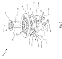
- the system of burners 1 adapted for installation in a cooking top 100 comprises a pair of substantially concentric burners 10, 20, said pair of burners 10, 20 comprising:
- the outlet section of the first apertures 12A and second apertures 22A is substantially parallel to the visible surface 101 of the cooking top 100, or slightly inclined relative to said visible surface 101.
- the outlet section of the first apertures 12A and second apertures 22A may be slightly inclined relative to a horizontal plane (i.e. a plane which is substantially parallel to the visible surface 101), e.g. by an angle between 0° and 30°, in particular an angle substantially equal to 15°.
- the particular realization of the first apertures 12A and second apertures 22A can be especially appreciated in a sectional view and when viewed in a direction substantially perpendicular to the axis A-A of the system of burners 1.
- said first apertures 12A and second apertures 22A are clearly realized in such a way as to generate a flame that propagates outwards from the system of burners 10 in a direction substantially parallel to said axis A-A of the system of burners 1, said first apertures 12A and second apertures 22A being thus so realized as to generate a "carpet flame", i.e. a flame that propagates outwards in a substantially vertical direction or anyway in a direction inclined by a very small angle relative to the vertical.
- the concentration of the first apertures 12A and second apertures 22A is in the range of one to ten per square centimetre (cm 2 ); as a result, the distance between each one of said first apertures 12A and each one of said second apertures 22A is not excessive, thus promoting flame propagation, while at the same time not being too small, so as to allow a sufficient supply of secondary air.
- first flame divider 12 and the second flame divider 22 provide the functions of delimiting the internal environment of the system of burners 1 at the top and of allowing the flame generated by the combustion of the air-gas mixture to exit the system of burners 1 through the plurality of first apertures 12A and second apertures 22A.
- the first flame divider 12 and the second flame divider 22 are so realized as to comprise a plurality of first apertures 12A and second apertures 22A, in particular having a diameter substantially equal to the thickness of the first flame divider 12 and second flame divider 22.
- first flame divider 12 and the second flame divider 22 are preferably situated at the same level with respect to the visible surface 101 of the cooking top 100; consequently, any means (not shown) for supporting cooking vessels containing foods to be cooked can have a reduced height, in accordance with the current design trends.
- the first cup 11 of the outer burner 10 and the second cup 12 of the inner burner 20 are made of die-cast aluminium; also, the first chamber 11A of the first cup 11 and the second chamber 21A of the second cup 21 are defined at the top by said first flame divider 12 and said second flame divider 22, respectively.
- the first cup 11 of the outer burner 10 comprises a first Venturi element 13 for supplying an air-gas mixture to a first chamber 11A of said first cup 11, and the second cup 21 of the inner burner 20 comprises a second Venturi element 23 for supplying an air-gas mixture to a second chamber 21A of said second cup 21.
- the first Venturi element 13 is made as one piece with the first cup 11 of the outer burner 10
- the second Venturi element 23 is made as one piece with the second cup 21 of the inner burner 20; however, it is clear that the first Venturi element 13 and the second Venturi element 23 may also be made separately from said outer burner 10 and inner burner 20, and then associated with said outer burner 10 and inner burner 20.
- the first Venturi element 13 and the second Venturi element 23 may be made as parts of a duct that includes them, or may themselves substantially constitute said duct in its entirety.
- the first Venturi element 13 and the second Venturi element 23 are so realized as to comprise, respectively, a first longitudinal axis of symmetry A1 and a second longitudinal axis of symmetry A2 arranged substantially horizontally (as shown in Figures 3a, 3b , 4 and 5 by means of a dashed-dotted line), said first Venturi element 13 being associated with the first cup 11 in a manner such that said first axis A1 is located on the outside of an inner wall 11B of the cup 11.
- said first Venturi element 13 is associated with the first cup 11 in such a way that said first axis 13A will not intersect said inner wall 11B of the cup 11; in a borderline case, said first axis 13A may be positioned tangentially relative to said inner wall 11B of the cup 11.
- the inner wall 11B of the cup 11 is preferably located on the outside of a projection along said first axis A1 of the outlet section (i.e. the section that enters the first chamber 11A) of the first Venturi element 13; it should be noted that in such a borderline situation (i.e. a situation in which the first axis A1 is positioned tangentially relative to said inner wall 11B), the inner wall 11B of the first cup 11 is preferably located on the outside of at least half the projection of the outlet section of the first Venturi element 13.
- Said first Venturi element 13 is associated with a partition 13A entering the first chamber 11A and positioned substantially parallel to the first axis A1 of the first Venturi element 13 and substantially tangent to the inner wall 11B of the cup 11.
- said partition 13A constitutes some sort of extension of the first Venturi element 13, in particular an extension that enters the first chamber 11A in such a way as to form a sort of guide for the air-gas mixture coming from the first Venturi element 13 and flowing into the first chamber 11A of the cup 11; it is therefore clear that this provision also allows the first Venturi element 13 to be substantially tangent to the inner wall 11B of the cup 11. It is also clear (as can be seen in the annexed drawings) that the first Venturi element 13 is associated with the first cup 11 in a manner such that the flow of air-gas mixture being fed to said first chamber 11A will be tangent to said inner wall 11B of the first cup 11.
- the first Venturi element 13 is associated with the first cup 11 in such a way that the inner wall 11B of the first cup 11 will not be directly hit by the flow of air-gas mixture exiting the first Venturi element 13.
- the provisions of the present invention allow, therefore, providing a system of burners 1 which is so realized as to prevent the air-gas mixture coming from the first Venturi element 13 from impacting directly against the inner wall 11B of the cup 11 and from being drastically slowed down and suddenly diverted upwards.
- the provisions of the present invention allow preventing said air-gas mixture from flowing out of said first apertures 12A of the first flame divider 12 at significantly different velocities, thus avoiding the onset of phenomena of incomplete ignition of the flame that should be produced by the outer burner 10, in particular because of the phenomenon known as "flame lift".
- the first cup 11 and the first chamber 11A have a substantially toroidal shape, wherein the inner wall 11B of the first cup 11 delimits a space suitable for receiving the second cup 21 of the inner burner 20; in particular, said inner wall 11B has a tubular and substantially cylindrical or truncated conical shape.
- the first cup 11 when viewed from above, is substantially shaped like a circular crown, and the second cup 21 is arranged substantially concentric in the central hole of the first cup 11, said central hole being delimited by the inner wall 11B of the first cup 11.
- the first cup 11 and the second cup 21 may be joined together.
- first Venturi element 13 and the second Venturi element 23 are positioned side by side, in particular in a manner such that the first axis A1 and the second axis A2 are substantially parallel and substantially lie in the same horizontal plane.
- first axis A1 of the first Venturi element 13 and the second axis A2 of the second Venturi element 23 are positioned in planes orthogonal to the plane in which the axis A-A of the system of burners 1 lies, said second axis A2 being preferably positioned in such a way as to intersect the axis A-A of the system of burners 1.
- the first Venturi element 13 receives a gas coming from a first injector 4A
- the second Venturi element 23 receives a gas coming from a second injector 4B.
- the first Venturi element 13 is associated with at least one first air intake 14 to allow entry of primary air, in particular said at least one first air intake 14 being associated with the first Venturi element 13 downstream of the first injector 4A with reference to the gas path.
- the second Venturi element 23 is associated with at least one second air intake 24 to allow entry of primary air, in particular said at least one second air intake 24 being associated with the second Venturi element 23 downstream of the second injector 4B with reference to the gas path.
- the first Venturi element 13 and the second Venturi element 23 create a pressure drop that drags primary air into them; the gas (enriched with primary air, i.e. the air-gas mixture) is then conveyed towards the combustion area of the system of burners 1.
- Primary air is air mixed with fuel gas inside the system of gas burners 1
- secondary air is air added to the already formed air-gas mixture in the area outside the cooking top 100 near the first apertures 12A and second apertures 22A of the system of gas burners 1, said “secondary air” being supplied when the flame has been ignited and being necessary for providing the additional Oxygen required for a proper combustion.
- said at least one first air intake 14 and said at least one second air intake 24 are sufficiently large to ensure an adequate flow of primary air through them.
- a primary air forced circulation system (not shown in the annexed drawings) may be associated with said system of burners 1.
- the system of burners 1 according to the present invention is designed to allow dragging a quantity of primary air in the range of 60% to 70% of the stoichiometric value, i.e. the quantity of air that would be necessary to ensure a proper combustion.
- the provisions of the present invention ensure an adequate flow of secondary air to reach an optimal stoichiometric value.
- system of gas burners 1 is of the type that takes primary air from below the cooking top 100.
- the system of burners 1 is so realized as to comprise a first tube and a second tube (not shown) associated with the injectors 4A, 4B and with independent control valves (also not shown), so that the outer burner 10 and the inner burner 20 can be used either jointly or separately. Consequently, in this preferred embodiment the system of burners 1 is of the double-crown, double-control type, and ensures good variability and a homogeneous distribution of the heat to be supplied to a cooking container positioned over said system of burners 1. It is however clear that the system of burners 1 according to the present invention may also be of the double-crown, single-control type, i.e. realized in such a way that the outer burner 10 and the inner burner 20 will be fed by a common gas inlet duct associated with a common tap or control valve (not shown).
- the first cup 11 and the first chamber 11A have a substantially toroidal shape, wherein the inner wall 11B of the first cup 11 delimits a central hole suitable for receiving the second cup 21 of the inner burner 20.
- the system of gas burners 1 comprises at least one opening 5 formed between the inner wall 11B of the first cup 11 and the second cup 21 of the inner burner 20 to allow the passage of secondary air (indicated by dashed arrows designated as AS in Fig. 6 ) taken from below the system of burners 1 (and also below the cooking top 100).
- said at least one opening 5 is associated with at least one first passage 15 (shown in Fig. 6 and Fig. 7 ) located between the upper portion of an inner edge of the first flame divider 12 and the lower portion of an outer edge of the second flame divider 22, so as to supply an adequate quantity of secondary air to the first apertures 12A (in particular, those first apertures 12A which are proximal to said inner edge of the first flame divider 12).
- first passage 15 shown in Fig. 6 and Fig. 7
- the second flame divider 22 lies in a horizontal plane which is higher than a horizontal plane in which the first flame divider 12 lies, said second flame divider 22 being so realized as to extend over said at least one first passage 15; such a realization of the second flame divider 22 prevents any liquid that might be spilled during the cooking process from flowing into said at least one first passage 15.
- Fig. 7 shows an embodiment of the system of burners 1 which is alternative to the one shown in Fig. 6 .
- said at least one opening 5 is preferably associated with at least one second passage 25 located between the second apertures 22A (in particular, the outer crown of said second apertures 22A) and the outer edge of the second flame divider 22, so as to supply an adequate quantity of secondary air to said second apertures 22A.
- said at least one second passage 25 is shaped substantially like an eyelet, in particular an eyelet shaped like a circular crown sector.
- said at least one second passage 25 comprises a plurality of second passages 25 located between the second apertures 22A and the outer edge of the second flame divider 22.
- said at least one second passage 25 is additional to said at least one first passage 15; however, said at least one second passage 25 may also be alternative to or substitutive of said at least one first passage 15.
- the first flame divider 12 is associated with a first frame 12B that allows coupling said first flame divider 12 to the first cup 11 of the outer burner 10.
- said first frame 12B is made of die-cast aluminium, and the first flame divider 12 is made from enamelled sheet metal, the union between the first flame divider 12 and the first frame 12B being accomplished through fastening means.
- Said first frame 12B allows the second apertures 22A of the second flame divider 22 to be kept in a slightly raised position relative to the cooking top 100 for the purpose of improving the supply of secondary air to the inner burner 20, so as to prevent the flames of said inner burner 20 from interfering with the flames of the outer burner 10.
- the second flame divider 22 is associated with a second frame 22B that allows coupling said second flame divider 22 to the second cup 21 of the inner burner 20.
- said second frame 22B is made of die-cast aluminium, and the second flame divider 22 is made from enamelled sheet metal, the union between the second flame divider 22 and the second frame 22B being accomplished through fastening means.
- system of burners 1 may comprise one or more of the following components:
- the first temperature sensor 7A and the second temperature sensor 7B interrupt the gas supply if the detected temperature falls below a predefined minimum value, the occurrence of such a condition being a signal for detecting that the air-gas mixture has not been ignited, resulting in the automatic closure of the on-off valve (not shown in the drawings) that supplies gas to of the system of burners 1.
- first ignition spark plug 6A and the first temperature sensor 7A are associated with the outer burner 10
- second ignition spark plug 6B and the second temperature sensor 7B are associated with the inner burner 20; it is clear that the outer burner 10 and the inner burner 20 may comprise connection means for associating said ignition spark plugs 6A, 6B and said temperature sensors 7A, 7B with the system of burner 1.
- the provisions of the present invention allow providing a system of burners 1 which is so realized as to prevent the air-gas mixture coming from the first Venturi element 13 from impacting directly against the inner wall 11B of the cup 11 and from being drastically slowed down and suddenly diverted upwards.
- the provisions of the present invention allow preventing said air-gas mixture from flowing out of said first apertures 12A of the first flame divider 12 at significantly different velocities, thus avoiding the onset of phenomena of incomplete ignition of the flame that should be produced by the outer burner 10, in particular because of the phenomenon known as "flame lift".
- the presence of at least one opening 5 formed between the inner wall 11B of the first cup 11 and the second cup 21 of the inner burner 20, and of said at least one first passage 15 and at least one second passage 25, allows supplying an adequate quantity of secondary air, taken from below the system of burners 1, to the first apertures 12A of the first flame divider 12 and to the second apertures 22A of the second flame divider 22; thanks to this provision, therefore, an adequate amount of oxygen can be supplied to the first apertures 12A and to the second apertures 22A to ensure a proper combustion.
- the system of burners 1 according to the present invention is so realized as to turn out to be particularly effective, in that it ensures optimal gas efficiency thanks to the first apertures 12A and second apertures 22A, which produce a "carpet flame".
- Another advantage of the system of burners 1 according to the present invention is that it avoids the creation of zones where the exit velocity of the primary air-gas mixture is different in the various perforated regions of the flame dividers 12, 22; as a consequence, the particular realization of the system of burners 1 according to the present invention allows preventing the occurrence of "flame lift" phenomena, particularly at ignition time.
- the present description has disclosed in detail a system of gas burners and a cooking top particularly suited for use in a household environment. Nevertheless, the present invention may also be conveniently implemented in systems of gas burners and cooking tops intended for different applications, e.g. in the hotel industry.
Landscapes
- Engineering & Computer Science (AREA)
- Chemical & Material Sciences (AREA)
- Combustion & Propulsion (AREA)
- Mechanical Engineering (AREA)
- General Engineering & Computer Science (AREA)
- Gas Burners (AREA)
Priority Applications (2)
| Application Number | Priority Date | Filing Date | Title |
|---|---|---|---|
| EP15179580.4A EP3128237A1 (fr) | 2015-08-03 | 2015-08-03 | Système de brûleurs à gaz, notamment pour une table de cuisson à usage ménager |
| US15/226,236 US10393386B2 (en) | 2015-08-03 | 2016-08-02 | System of gas burners, in particular for a cooking top for household use |
Applications Claiming Priority (1)
| Application Number | Priority Date | Filing Date | Title |
|---|---|---|---|
| EP15179580.4A EP3128237A1 (fr) | 2015-08-03 | 2015-08-03 | Système de brûleurs à gaz, notamment pour une table de cuisson à usage ménager |
Publications (1)
| Publication Number | Publication Date |
|---|---|
| EP3128237A1 true EP3128237A1 (fr) | 2017-02-08 |
Family
ID=54251917
Family Applications (1)
| Application Number | Title | Priority Date | Filing Date |
|---|---|---|---|
| EP15179580.4A Withdrawn EP3128237A1 (fr) | 2015-08-03 | 2015-08-03 | Système de brûleurs à gaz, notamment pour une table de cuisson à usage ménager |
Country Status (2)
| Country | Link |
|---|---|
| US (1) | US10393386B2 (fr) |
| EP (1) | EP3128237A1 (fr) |
Cited By (2)
| Publication number | Priority date | Publication date | Assignee | Title |
|---|---|---|---|---|
| CN108151021A (zh) * | 2018-01-05 | 2018-06-12 | 余馨恬 | 一种燃烧方法 |
| CN111372501A (zh) * | 2017-09-27 | 2020-07-03 | 德隆奇电器单一股东有限责任公司 | 用于烹饪食物的自主装置以及烹饪方法 |
Families Citing this family (4)
| Publication number | Priority date | Publication date | Assignee | Title |
|---|---|---|---|---|
| US10551056B2 (en) * | 2017-02-23 | 2020-02-04 | Whirlpool Corporation | Burner base |
| US11098892B2 (en) | 2019-06-27 | 2021-08-24 | Bsh Home Appliances Corporation | Dual venturi single chamber gas burner |
| CN112393237B (zh) * | 2020-12-02 | 2025-01-21 | 杭州老板电器股份有限公司 | 一种燃烧器及灶具 |
| US11940148B2 (en) | 2021-10-28 | 2024-03-26 | Electrolux Appliances Aktiebolag | Multi injection dual ring gas burner for domestic gas cooking units |
Citations (9)
| Publication number | Priority date | Publication date | Assignee | Title |
|---|---|---|---|---|
| US1568853A (en) * | 1925-02-17 | 1926-01-05 | Joseph P Lane | Stove burner and water heater |
| EP0732541A2 (fr) * | 1995-03-17 | 1996-09-18 | OVER ALL srl | Brûleur à gaz pour des tables de cuisson en vitrocéramique et pour le chauffage |
| CN2288371Y (zh) * | 1997-01-10 | 1998-08-19 | 国营大众机械厂 | 具有碟形旋火火盖的燃气灶具燃烧器 |
| US20030190573A1 (en) * | 2002-04-09 | 2003-10-09 | Keem Phillip William | Burner with tangential gas inlet |
| WO2007036772A1 (fr) * | 2005-09-30 | 2007-04-05 | Indesit Company S.P.A. | Surface de cuisson à brûleur à gaz comprenant un élément semi-perméable |
| US20100326420A1 (en) * | 2007-02-27 | 2010-12-30 | Indesit Company S.P. A. | Cooking top |
| EP2503237A2 (fr) * | 2011-03-22 | 2012-09-26 | BSH Bosch und Siemens Hausgeräte GmbH | Four à gaz |
| US20140060517A1 (en) * | 2011-02-14 | 2014-03-06 | Hangzhou Robam Appliances Co., Ltd. | Burner |
| FR2999276A1 (fr) * | 2012-12-10 | 2014-06-13 | Applic Gaz Sa | Bruleur a gaz comprenant une tete de bruleur |
Family Cites Families (1)
| Publication number | Priority date | Publication date | Assignee | Title |
|---|---|---|---|---|
| CN105934633B (zh) * | 2014-01-14 | 2019-01-22 | 德芬迪意大利有限责任公司 | 用于烹饪搁架的气体燃烧器 |
-
2015
- 2015-08-03 EP EP15179580.4A patent/EP3128237A1/fr not_active Withdrawn
-
2016
- 2016-08-02 US US15/226,236 patent/US10393386B2/en active Active
Patent Citations (9)
| Publication number | Priority date | Publication date | Assignee | Title |
|---|---|---|---|---|
| US1568853A (en) * | 1925-02-17 | 1926-01-05 | Joseph P Lane | Stove burner and water heater |
| EP0732541A2 (fr) * | 1995-03-17 | 1996-09-18 | OVER ALL srl | Brûleur à gaz pour des tables de cuisson en vitrocéramique et pour le chauffage |
| CN2288371Y (zh) * | 1997-01-10 | 1998-08-19 | 国营大众机械厂 | 具有碟形旋火火盖的燃气灶具燃烧器 |
| US20030190573A1 (en) * | 2002-04-09 | 2003-10-09 | Keem Phillip William | Burner with tangential gas inlet |
| WO2007036772A1 (fr) * | 2005-09-30 | 2007-04-05 | Indesit Company S.P.A. | Surface de cuisson à brûleur à gaz comprenant un élément semi-perméable |
| US20100326420A1 (en) * | 2007-02-27 | 2010-12-30 | Indesit Company S.P. A. | Cooking top |
| US20140060517A1 (en) * | 2011-02-14 | 2014-03-06 | Hangzhou Robam Appliances Co., Ltd. | Burner |
| EP2503237A2 (fr) * | 2011-03-22 | 2012-09-26 | BSH Bosch und Siemens Hausgeräte GmbH | Four à gaz |
| FR2999276A1 (fr) * | 2012-12-10 | 2014-06-13 | Applic Gaz Sa | Bruleur a gaz comprenant une tete de bruleur |
Cited By (4)
| Publication number | Priority date | Publication date | Assignee | Title |
|---|---|---|---|---|
| CN111372501A (zh) * | 2017-09-27 | 2020-07-03 | 德隆奇电器单一股东有限责任公司 | 用于烹饪食物的自主装置以及烹饪方法 |
| CN111372501B (zh) * | 2017-09-27 | 2023-03-07 | 德隆奇电器单一股东有限责任公司 | 用于烹饪食物的自主烹饪装置以及烹饪方法 |
| CN108151021A (zh) * | 2018-01-05 | 2018-06-12 | 余馨恬 | 一种燃烧方法 |
| CN108151021B (zh) * | 2018-01-05 | 2019-03-26 | 余馨恬 | 一种燃烧方法 |
Also Published As
| Publication number | Publication date |
|---|---|
| US10393386B2 (en) | 2019-08-27 |
| US20170038077A1 (en) | 2017-02-09 |
Similar Documents
| Publication | Publication Date | Title |
|---|---|---|
| US10393386B2 (en) | System of gas burners, in particular for a cooking top for household use | |
| US9127838B2 (en) | Gas burner for cooking appliances | |
| US11441781B2 (en) | System of gas burners, in particular for a cooking top for household use | |
| EP2572141B1 (fr) | Brûleur à gaz aux anneaux de flamme multiples | |
| US8932049B2 (en) | Top-burner and cooker comprising the same | |
| US20080202494A1 (en) | Gas Burner for Cooking Appliances | |
| US20100154776A1 (en) | Cooking range burner head assembly | |
| US20100186730A1 (en) | Gas burner | |
| US8863735B2 (en) | Gas burner assembly | |
| US8381714B2 (en) | Burner for cooking appliances | |
| KR20140137721A (ko) | 이중 버너 형태의 가스 버너 | |
| TR201906118T4 (tr) | Mutfak ocağı için gaz brülörü. | |
| EP2390569B1 (fr) | Brûleur pour cuisinières à gaz professionnelles ou domestiques, particulièrement les brûleurs à flamme verticale adaptés à la cuisson de woks et similaire | |
| US20060147865A1 (en) | Cooking range burner head assembly | |
| EP3128235A1 (fr) | Brûleur à gaz, notamment pour une table de cuisson à usage ménager | |
| TW202022293A (zh) | 瓦斯爐用燃燒器以及瓦斯爐 | |
| US6131561A (en) | Burner with secondary air stability ring | |
| JP6842957B2 (ja) | コンロバーナ | |
| EP3591289B1 (fr) | Brûleur à deux circuits, agencement de brûleur à gaz et cuisinière à gaz | |
| JP6635778B2 (ja) | コンロ用バーナ、及びそれを備えたコンロ | |
| CN220355418U (zh) | 一种外环火盖及燃烧器 | |
| JP2019158234A (ja) | ガスコンロ | |
| US20220221146A1 (en) | Double-stacked gas burner | |
| KR101304847B1 (ko) | 빌트인 타입 조리기기 | |
| KR20100069015A (ko) | 탑버너 및 이를 포함하는 조리기기 |
Legal Events
| Date | Code | Title | Description |
|---|---|---|---|
| PUAI | Public reference made under article 153(3) epc to a published international application that has entered the european phase |
Free format text: ORIGINAL CODE: 0009012 |
|
| AK | Designated contracting states |
Kind code of ref document: A1 Designated state(s): AL AT BE BG CH CY CZ DE DK EE ES FI FR GB GR HR HU IE IS IT LI LT LU LV MC MK MT NL NO PL PT RO RS SE SI SK SM TR |
|
| AX | Request for extension of the european patent |
Extension state: BA ME |
|
| RAP1 | Party data changed (applicant data changed or rights of an application transferred) |
Owner name: WHIRLPOOL EMEA S.P.A |
|
| 17P | Request for examination filed |
Effective date: 20170808 |
|
| RBV | Designated contracting states (corrected) |
Designated state(s): AL AT BE BG CH CY CZ DE DK EE ES FI FR GB GR HR HU IE IS IT LI LT LU LV MC MK MT NL NO PL PT RO RS SE SI SK SM TR |
|
| 17Q | First examination report despatched |
Effective date: 20180830 |
|
| STAA | Information on the status of an ep patent application or granted ep patent |
Free format text: STATUS: THE APPLICATION HAS BEEN WITHDRAWN |
|
| 18W | Application withdrawn |
Effective date: 20190215 |