EP3128255B1 - Verfahren zur herstellung einer sonnenwärmesammlungsvorrichtung - Google Patents
Verfahren zur herstellung einer sonnenwärmesammlungsvorrichtung Download PDFInfo
- Publication number
- EP3128255B1 EP3128255B1 EP15774204.0A EP15774204A EP3128255B1 EP 3128255 B1 EP3128255 B1 EP 3128255B1 EP 15774204 A EP15774204 A EP 15774204A EP 3128255 B1 EP3128255 B1 EP 3128255B1
- Authority
- EP
- European Patent Office
- Prior art keywords
- exhaust hole
- tube
- sealing member
- inner tube
- heat collecting
- Prior art date
- Legal status (The legal status is an assumption and is not a legal conclusion. Google has not performed a legal analysis and makes no representation as to the accuracy of the status listed.)
- Active
Links
- 238000004519 manufacturing process Methods 0.000 title claims description 6
- 238000007789 sealing Methods 0.000 claims description 54
- 238000003466 welding Methods 0.000 claims description 14
- 229910052751 metal Inorganic materials 0.000 claims description 13
- 239000002184 metal Substances 0.000 claims description 13
- 238000000034 method Methods 0.000 claims description 10
- 238000010438 heat treatment Methods 0.000 claims description 7
- 230000002040 relaxant effect Effects 0.000 claims description 5
- 239000000155 melt Substances 0.000 claims description 2
- 230000008878 coupling Effects 0.000 description 21
- 238000010168 coupling process Methods 0.000 description 21
- 238000005859 coupling reaction Methods 0.000 description 21
- 239000000463 material Substances 0.000 description 10
- 239000011521 glass Substances 0.000 description 8
- XEEYBQQBJWHFJM-UHFFFAOYSA-N Iron Chemical compound [Fe] XEEYBQQBJWHFJM-UHFFFAOYSA-N 0.000 description 6
- 230000003287 optical effect Effects 0.000 description 4
- 229910000851 Alloy steel Inorganic materials 0.000 description 3
- 229910000975 Carbon steel Inorganic materials 0.000 description 3
- 229910000831 Steel Inorganic materials 0.000 description 3
- 229910052782 aluminium Inorganic materials 0.000 description 3
- XAGFODPZIPBFFR-UHFFFAOYSA-N aluminium Chemical compound [Al] XAGFODPZIPBFFR-UHFFFAOYSA-N 0.000 description 3
- 239000010962 carbon steel Substances 0.000 description 3
- 229910052742 iron Inorganic materials 0.000 description 3
- 239000010935 stainless steel Substances 0.000 description 3
- 229910001220 stainless steel Inorganic materials 0.000 description 3
- 239000010959 steel Substances 0.000 description 3
- 239000000470 constituent Substances 0.000 description 2
- 238000010894 electron beam technology Methods 0.000 description 2
- 229910000833 kovar Inorganic materials 0.000 description 2
- 238000012856 packing Methods 0.000 description 2
- 238000004544 sputter deposition Methods 0.000 description 2
- UFHFLCQGNIYNRP-UHFFFAOYSA-N Hydrogen Chemical compound [H][H] UFHFLCQGNIYNRP-UHFFFAOYSA-N 0.000 description 1
- 239000006096 absorbing agent Substances 0.000 description 1
- 230000015572 biosynthetic process Effects 0.000 description 1
- 239000005388 borosilicate glass Substances 0.000 description 1
- 239000011195 cermet Substances 0.000 description 1
- 230000007547 defect Effects 0.000 description 1
- 230000001419 dependent effect Effects 0.000 description 1
- 238000007599 discharging Methods 0.000 description 1
- 229910052739 hydrogen Inorganic materials 0.000 description 1
- 239000001257 hydrogen Substances 0.000 description 1
- 238000012423 maintenance Methods 0.000 description 1
- 239000012528 membrane Substances 0.000 description 1
- 239000012466 permeate Substances 0.000 description 1
- 229910000679 solder Inorganic materials 0.000 description 1
Images



Classifications
-
- F—MECHANICAL ENGINEERING; LIGHTING; HEATING; WEAPONS; BLASTING
- F24—HEATING; RANGES; VENTILATING
- F24S—SOLAR HEAT COLLECTORS; SOLAR HEAT SYSTEMS
- F24S10/00—Solar heat collectors using working fluids
- F24S10/40—Solar heat collectors using working fluids in absorbing elements surrounded by transparent enclosures, e.g. evacuated solar collectors
- F24S10/45—Solar heat collectors using working fluids in absorbing elements surrounded by transparent enclosures, e.g. evacuated solar collectors the enclosure being cylindrical
-
- F—MECHANICAL ENGINEERING; LIGHTING; HEATING; WEAPONS; BLASTING
- F24—HEATING; RANGES; VENTILATING
- F24S—SOLAR HEAT COLLECTORS; SOLAR HEAT SYSTEMS
- F24S23/00—Arrangements for concentrating solar-rays for solar heat collectors
- F24S23/70—Arrangements for concentrating solar-rays for solar heat collectors with reflectors
- F24S23/74—Arrangements for concentrating solar-rays for solar heat collectors with reflectors with trough-shaped or cylindro-parabolic reflective surfaces
-
- F—MECHANICAL ENGINEERING; LIGHTING; HEATING; WEAPONS; BLASTING
- F24—HEATING; RANGES; VENTILATING
- F24S—SOLAR HEAT COLLECTORS; SOLAR HEAT SYSTEMS
- F24S40/00—Safety or protection arrangements of solar heat collectors; Preventing malfunction of solar heat collectors
- F24S40/80—Accommodating differential expansion of solar collector elements
-
- F—MECHANICAL ENGINEERING; LIGHTING; HEATING; WEAPONS; BLASTING
- F24—HEATING; RANGES; VENTILATING
- F24S—SOLAR HEAT COLLECTORS; SOLAR HEAT SYSTEMS
- F24S70/00—Details of absorbing elements
- F24S70/20—Details of absorbing elements characterised by absorbing coatings; characterised by surface treatment for increasing absorption
- F24S70/225—Details of absorbing elements characterised by absorbing coatings; characterised by surface treatment for increasing absorption for spectrally selective absorption
-
- F—MECHANICAL ENGINEERING; LIGHTING; HEATING; WEAPONS; BLASTING
- F24—HEATING; RANGES; VENTILATING
- F24S—SOLAR HEAT COLLECTORS; SOLAR HEAT SYSTEMS
- F24S80/00—Details, accessories or component parts of solar heat collectors not provided for in groups F24S10/00-F24S70/00
- F24S80/70—Sealing means
-
- F—MECHANICAL ENGINEERING; LIGHTING; HEATING; WEAPONS; BLASTING
- F24—HEATING; RANGES; VENTILATING
- F24S—SOLAR HEAT COLLECTORS; SOLAR HEAT SYSTEMS
- F24S20/00—Solar heat collectors specially adapted for particular uses or environments
- F24S20/20—Solar heat collectors for receiving concentrated solar energy, e.g. receivers for solar power plants
-
- F—MECHANICAL ENGINEERING; LIGHTING; HEATING; WEAPONS; BLASTING
- F24—HEATING; RANGES; VENTILATING
- F24S—SOLAR HEAT COLLECTORS; SOLAR HEAT SYSTEMS
- F24S25/00—Arrangement of stationary mountings or supports for solar heat collector modules
- F24S25/60—Fixation means, e.g. fasteners, specially adapted for supporting solar heat collector modules
- F24S2025/6011—Fixation means, e.g. fasteners, specially adapted for supporting solar heat collector modules by welding or brazing
-
- F—MECHANICAL ENGINEERING; LIGHTING; HEATING; WEAPONS; BLASTING
- F24—HEATING; RANGES; VENTILATING
- F24S—SOLAR HEAT COLLECTORS; SOLAR HEAT SYSTEMS
- F24S25/00—Arrangement of stationary mountings or supports for solar heat collector modules
- F24S25/60—Fixation means, e.g. fasteners, specially adapted for supporting solar heat collector modules
- F24S2025/6012—Joining different materials
- F24S2025/6013—Joining glass with non-glass elements
-
- Y—GENERAL TAGGING OF NEW TECHNOLOGICAL DEVELOPMENTS; GENERAL TAGGING OF CROSS-SECTIONAL TECHNOLOGIES SPANNING OVER SEVERAL SECTIONS OF THE IPC; TECHNICAL SUBJECTS COVERED BY FORMER USPC CROSS-REFERENCE ART COLLECTIONS [XRACs] AND DIGESTS
- Y02—TECHNOLOGIES OR APPLICATIONS FOR MITIGATION OR ADAPTATION AGAINST CLIMATE CHANGE
- Y02E—REDUCTION OF GREENHOUSE GAS [GHG] EMISSIONS, RELATED TO ENERGY GENERATION, TRANSMISSION OR DISTRIBUTION
- Y02E10/00—Energy generation through renewable energy sources
- Y02E10/40—Solar thermal energy, e.g. solar towers
-
- Y—GENERAL TAGGING OF NEW TECHNOLOGICAL DEVELOPMENTS; GENERAL TAGGING OF CROSS-SECTIONAL TECHNOLOGIES SPANNING OVER SEVERAL SECTIONS OF THE IPC; TECHNICAL SUBJECTS COVERED BY FORMER USPC CROSS-REFERENCE ART COLLECTIONS [XRACs] AND DIGESTS
- Y02—TECHNOLOGIES OR APPLICATIONS FOR MITIGATION OR ADAPTATION AGAINST CLIMATE CHANGE
- Y02E—REDUCTION OF GREENHOUSE GAS [GHG] EMISSIONS, RELATED TO ENERGY GENERATION, TRANSMISSION OR DISTRIBUTION
- Y02E10/00—Energy generation through renewable energy sources
- Y02E10/40—Solar thermal energy, e.g. solar towers
- Y02E10/44—Heat exchange systems
Definitions
- This invention relates to a method of manufacturing a solar heat collection apparatus, and more particularly to a trough type solar heat collection apparatus.
- a heating medium flowing through the heat collecting tube is heated.
- the heat collecting tube used in this solar heat collection apparatus has a duplex tube structure formed of a glass outer tube and a metal inner tube so that sunlight is efficiently converted into heat, enabling a reduction in heat loss. Further, an enclosed space set in a vacuum condition is provided between the outer tube and the inner tube.
- an exhaust hole is provided in the outer tube, and after air has been discharged through the exhaust hole, the glass tube is heated and sealed.
- a sealing mark remains in the form of a projecting bump in the location where the exhaust hole was sealed.
- the projecting part of the sealing mark may be struck while installing the solar heat collection apparatus or handling the heat collecting tube during maintenance, and as a result, the outer tube may be damaged.
- the heat collecting tube is packed into a box made of a hard material, such as a wooden box, the projecting bump part may strike a wall of the box or an adjacent heat collecting tube such that the outer tube is damaged. Therefore, when the heat collecting tube is packed into a box or the like, packing must be performed while taking into consideration orientations and positions of individual heat collecting tubes, making the packing operation laborious.
- document JP S59-77252 A describes attaching an exhaust tip tube to a metal support tube that is provided between the inner tube and the outer tube in order to support the inner tube relative to the outer tube, discharging air by connecting a vacuum pump to the exhaust tip tube, and then sealing the exhaust tip tube.
- Document GB 2 005 823 A describes a heat collecting tube with an end cap having a small hole utilized during the manufacturing process for de-pressurizing, said small hole being then closed by a spot of solder.
- the exhaust tip tube that is attached to the support tube provided between the inner tube and the outer tube is sealed at an end portion of the heat collecting tube while projecting in an identical direction to an extension direction of the heat collecting tube.
- a plurality of heat collecting tubes are connected in succession at respective end portions thereof so as to extend in a lengthwise direction. Therefore, if the exhaust tip tube projects when the end portions of respective heat collecting tubes are connected to each other, a space for the exhaust tip tube must be secured in the lengthwise direction, leading to a corresponding reduction in an effective length by which the end portions can be connected to each other, and as a result, the heat collecting tubes cannot be connected easily.
- This invention has been designed to solve the problems described above, and the object thereof is to provide a method of manufacturing a solar heat collection apparatus with which damage to an outer tube can be prevented and heat collecting tubes can be easily connected to each other in a lengthwise direction.
- a solar heat collection apparatus heats a heating medium flowing through a heat collecting tube by collecting sunlight in the heat collecting tube using light collecting means, wherein the heat collecting tube includes an inner tube through which the heating medium flows, an outer tube provided on an outer side of the inner tube, and a connecting member connecting the inner tube to the outer tube, an insulating space is formed between the inner tube and the outer tube, an exhaust hole that communicates with the insulating space is formed in the connecting member, and the exhaust hole is sealed by a sealing member welded to the connecting member.
- the connecting member of the solar heat collection apparatus may include a flange connected to the inner tube and a stress relaxing member provided between the flange and the outer tube, and the exhaust hole may be formed in the flange.
- sealing member is welded to the connecting member by friction welding.
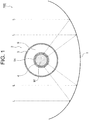
- a solar heat collection apparatus 100 includes a curved surface mirror 1 serving as light collecting means, and a heat collecting tube 2 disposed on an inner side of the curved surface mirror 1.
- the curved surface mirror 1 is formed to have a parabolic surface-shaped cross-section that extends in a lengthwise direction.
- an inner surface of the curved surface mirror 1 is formed as a mirror surface, and the heat collecting tube 2 is supported in a focal position of the mirror surface so as to extend in the lengthwise direction.
- sunlight L incident on the curved surface mirror 1 is reflected by the inner surface of the curved surface mirror 1 so as to enter the heat collecting tube 2.
- the heat collecting tube 2 has a duplex tube structure formed of a metal inner tube 4 through which a heating medium M flows, and a glass outer tube 3 provided on an outer side of the inner tube 4.
- An insulating space 9 maintained in a vacuum condition is formed between the inner tube 4 and the outer tube 3.
- the length of the inner tube 4 and the outer tube 3 in the lengthwise direction is approximately 4 m.
- An optical selective film 14 is formed on an outer surface of the inner tube 4.
- the optical selective film 14 is capable of absorbing visible light rays and near infrared rays from the sunlight L, and reflecting far ultraviolet rays emitted from the heating medium M.
- glass such as borosilicate glass is used for the outer tube 3.
- a heat resistant metal such as an iron-based material (for example, stainless steel, heat resistant steel, steel alloy, or carbon steel) or an aluminum-based material may be used.
- the optical selective film 14 is formed from a laminated body having a metal layer, a cermet layer, and a dielectric layer, for example.
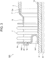
- Flanges 8a, 8b forming a pair of substantially disc-shaped members, each having an opening in a central part thereof, are attached to respective ends of the inner tube 4, and the flanges 8a, 8b are disposed so as to sandwich the outer tube 3 from either side on an outer periphery of the inner tube 4.
- the flanges are members that are attached perpendicularly to the outer periphery of the inner tube 4.
- Inner sides of the flanges 8a, 8b, or in other words parts thereof close to the inner tube 4, are shaped as substantially annular recesses recessed toward the interior of the insulating space 9.
- a substantially cylindrical part by which the flange 8a is attached fixedly to the inner tube 4 serves as an attachment portion 8a1.
- the optical selective film 14 is disposed only in the insulating space 9, and therefore the attachment portion 8a1 is attached directly to the inner tube 4.
- a substantially annular flat part on an outer side of the flange 8a serves as a flat portion 8a2.
- An end portion of the attachment portion 8a1 is positioned so as to be flush with the flat portion 8a2 of the flange 8a in the lengthwise direction.
- an exhaust hole 18 that communicates with the insulating space 9 is formed in the flat portion 8a2 of the flange 8a, and the exhaust hole 18 is sealed by a metal sealing member 20.
- one end of a substantially cylindrical bellows 7 that includes a bellows-shaped part is connected to the flat portion 8a2 of each flange 8a, 8b.
- One end of a substantially cylindrical cylinder member 15 is connected to the other end of each of the pair of bellows 7.
- Other ends of the pair of cylinder members 15 are connected to the respective ends of the outer tube 3.
- an end portion 15a of the cylinder member 15 on the side connected to the outer tube 3 is formed as a sharp edge, and the end portion 15a formed as a sharp edge is fixed by being inserted into the outer tube 3.
- the flanges 8a, 8b, the bellows 7, and the cylinder member 15 connect the inner tube 4 to the outer tube 3.
- the flanges 8a, 8b, the bellows 7, and the cylinder members 15 together constitute a connecting member.
- the bellows 7 provided between the flanges 8a, 8b and the outer tube 3 constitute stress relaxing members.
- the bellows 7 When the inner tube 4 undergoes thermal expansion so as to expand in the lengthwise direction, the bellows 7 also expands in the lengthwise direction, thereby absorbing a difference between respective coefficients of thermal expansion of the outer tube 3 and the inner tube 4.
- a heat resistant metal such as an iron-based material (for example, stainless steel, heat resistant steel, steel alloy, or carbon steel) or an aluminum-based material, for example, may be used as the material of the flanges 8a, 8b and the bellows 7.
- Kovar metal which has a linear expansion coefficient similar to the glass of the outer tube 3, is used for the cylinder members 15.
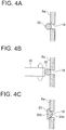
- Fig. 4 shows a process for sealing the exhaust hole 18.
- a portion 20a of the sealing member 20 on the insulating space 9 side is pushed into the exhaust hole 18, while a remaining portion 20b is pressed flat so as to spread over the flange 8a and welded at a predetermined thickness.
- the exhaust hole 18 is sealed by the sealing member 20, which is welded to the flange 8a by friction welding.
- the exhaust hole 18 is formed in the flange 8a and sealed by the sealing member 20 instead of an exhaust hole being formed in the outer tube 3, and therefore the risk of the glass outer tube 3 being damaged when a sealing mark of the exhaust hole is struck by another object can be eliminated.
- the exhaust hole 18 is sealed by welding the sealing member 20 directly to the flange 8a on the periphery of the exhaust hole 18, and therefore the sealing trace of the exhaust hole 18 does not project in the lengthwise direction.
- a sufficient effective length can be secured in the lengthwise direction to connect end portions of a plurality of the heat collecting tubes 2 to each other, and as a result, the heat collecting tubes 2 can be easily connected to each other.
- the exhaust hole 18 is sealed by friction-welding the sealing member 20 to the flange 8a.
- a current may be passed through the sealing member 20 so that the exhaust hole 18 is sealed by resistance welding.
- the electrical resistance of the sealing member 20 may be uneven, and it may therefore be impossible to ensure that the portion 20b of the sealing member 20 deforms in a uniform manner.
- the sealing member 20 merely needs to be pushed by the rotating rod 30, and therefore the portion 20b of the sealing member 20 can be deformed in a uniform manner, with the result that the exhaust hole 18 can be sealed more reliably.
- the exhaust hole 18 may also be sealed by performing electron beam welding on the sealing member 20. In this case, however, sputtering may occur in the sealing member 20. When the sealing member 20 is welded to the flange 8a by friction welding, on the other hand, sputtering does not occur, and therefore the likelihood of defects being formed in the sealed part of the exhaust hole 18 can be reduced.
- the formation position of the exhaust hole 18 is not limited to the flange 8a, and the exhaust hole 18 may be formed in the cylinder member 15 instead.
- Fig. 5 shows a configuration of a heat collecting tube 2' of a solar heat collection apparatus 200. Note that numerals identical to the reference numerals used in Figs. 1 to 3 denote identical or similar constituent components, and detailed description of these constituent components has been omitted.
- a substantially conical first coupling member 11 is attached to an outer periphery of one end portion of the outer tube 3.
- the first coupling member 11 is constituted by a substantially cylindrical attachment portion 11a having a substantially L-shaped cross section, a conical portion 11b having a partially cut-away cone shape, and a substantially ring-shaped annular portion 11c.
- the conical portion 11b increases in diameter from an end portion of the heat collecting tube 2' toward the center thereof.
- a small diameter end of the conical portion 11b is connected integrally to the attachment portion 11a, and a large diameter end of the conical portion 11b is connected integrally to an inside edge portion of the annular portion 11c.
- one side of the substantially L-shaped cross-section of the attachment portion 11a of the first coupling member 11 extends toward the center side of the heat collecting tube 2', and is fixed to the outer surface of the inner tube 4.
- the first coupling member 11 is attached to the outer surface of the inner tube 4 by the attachment portion 11a.
- one end of the bellows 7 is connected to the annular portion 11c, and a substantially cylindrical second coupling member 16 is connected to the other end of the bellows 7.
- the second coupling member 16 is constituted by an annular portion 16a to which one end of the bellows 7 is connected, and a substantially cylindrical cylinder portion 16b connected to an outside edge portion of the annular portion 16a.
- the annular portion 16a is perpendicular to the inner tube 4, and the attachment portion 11a of the first coupling member 11 is positioned further toward the center side of the heat collecting tube 2' than the annular portion 16a of the second coupling member 16 in the lengthwise direction. Further, an end portion of the cylinder portion 16b of the second coupling member 16 on a side that does not contact the annular portion 16a, or in other words an end portion 16c on the side that is connected to the outer tube 3, is formed as a sharp edge, and the sharp edge is fixed by being inserted into the outer tube 3. Thus, the outer tube 3 and the inner tube 4 are connected to each other via the bellows 7, the first coupling member 11, and the second coupling member 16. Moreover, an exhaust hole 28 is formed in the cylinder portion 16b of the second coupling member 16. The exhaust hole 28 is sealed by the sealing member 20, which is welded to the cylinder portion 16b by friction welding.
- the bellows 7, the first coupling member 11, and the second coupling member 16 together constitute the connecting member.
- the bellows 7 serving as the stress relaxing member contracts when the inner tube 4 undergoes thermal expansion so as to expand in the lengthwise direction, thereby absorbing the difference between the respective coefficients of thermal expansion of the outer tube 3 and the inner tube 4.
- a heat resistant metal such as an iron-based material (for example, stainless steel, heat resistant steel, steel alloy, or carbon steel) or an aluminum-based material, for example, may be used as the material of the first coupling member 11.
- Kovar metal which has a linear expansion coefficient similar to the glass of the outer tube 3, is used for the second coupling member 16.
- the exhaust hole 28 is formed in the second coupling member 16 serving as the connecting member, and therefore the risk of damage to the outer tube 3 is reduced. Further, the exhaust hole 28 is formed in the cylinder portion 16b of the second coupling member 16, which is positioned on a side face of the heat collecting tube 2, and therefore no sealing trace of the exhaust hole remains on the lengthwise direction side of the heat collecting tube 2'. Hence, a plurality of the heat collecting tubes 2' can be easily connected to each other in the lengthwise direction. Furthermore, the exhaust hole 28 is sealed by welding the sealing member 20 to the second coupling member 16 by friction welding, and therefore the exhaust hole 28 can be sealed more reliably than with resistance welding or electron beam welding.
- the shape of the sealing member is not limited to the ball-shaped sealing member 20 shown in Fig. 4A . More specifically, a columnar sealing member 21 such as that shown in Fig. 6A may be used instead. Alternatively, a sealing member 22 having a shape combining a column and a ball, such as that shown in Fig. 6B , may be employed. Further, a sealing member 23 having a shape combining a small diameter column with a ball, such as that shown in Fig. 6C , may be employed. Furthermore, a sealing member 24 having a shape combining a column and a cone, such as that shown in Fig. 6D , may be employed.
- the shape of the connecting member in which the exhaust hole 18 or 28 is formed is not limited to the shapes shown in Figs. 3 and 5 . More specifically, as shown in Fig. 7A , a flange 38a formed with an exhaust hole 48 may include a substantially columnar projecting portion, and the exhaust hole 48 may be formed in the center of the projecting portion. Alternatively, as shown in Fig. 7B , a flange 58a having a projecting shape only in a location where an exhaust hole 68 is formed may be used.
Landscapes
- Engineering & Computer Science (AREA)
- Physics & Mathematics (AREA)
- Chemical & Material Sciences (AREA)
- Sustainable Development (AREA)
- Sustainable Energy (AREA)
- Thermal Sciences (AREA)
- Life Sciences & Earth Sciences (AREA)
- Combustion & Propulsion (AREA)
- Mechanical Engineering (AREA)
- General Engineering & Computer Science (AREA)
- Spectroscopy & Molecular Physics (AREA)
- Joints Allowing Movement (AREA)
- Optical Elements Other Than Lenses (AREA)
- Photovoltaic Devices (AREA)
Claims (2)
- Verfahren zum Herstellen einer Solarwärmesammelvorrichtung, wobei das Wärmesammelrohr (2; 2') umfasst:ein inneres Rohr (4), durch das das durch Sonnenlicht erwärmtes Wärmemedium (M) fließt;und ein äußeres Rohr (3), das an einer Außenseite des inneren Rohrs (4) bereitgestellt ist; undein Verbindungselement (7, 8a, 8b, 15; 11, 16; 38a; 58a), das das innere Rohr (4) mit dem äußeren Rohr (3) verbindet, und ein isolierender Raum (9) zwischen dem inneren Rohr (4) und dem äußeren Rohr (3) ausgebildet ist,wobei das Verfahren einen Schritt umfasst, Luft in dem isolierendem Raum (9) durch eine Auslassbohrung (18) unter Verwendung einer Unterdruckpumpe zu evakuieren, sodass das Innere des isolierenden Raums in einen Unterdruckzustand versetzt ist;einen Schritt, eine Metallkugel, die einen größeren Durchmesser als die Auslassbohrung (18) aufweist, als ein Dichtelement (20) in Berührung mit der Auslassbohrung (18; 28; 48; 68) zu bringen, die in dem Verbindungselement ausgebildet ist und mit dem isolierenden Raum (9) in Verbindung ist, und die Metallkugel vorübergehend daran zu befestigen;und einen Schritt, das Dichtelement (20) durch eine drehende Stange (30) zu schieben und das Dichtelement (20) mit dem Verbindungselement mittels Reibung zu verschweißen,in dem das Dichtelement (20) schmilzt, um durch die durch die drehende Stange (30) erzeugte Reibungswärme so zu verformen, dass ein Abschnitt (20a) des Dichtelements (20) zu der Auslassbohrung (18; 28; 48; 68) geschoben wird, um die Auslassbohrung (18; 28; 48; 68) abzudichten, und das verbleibende Teil (20b) des Dichtelements (20) mit dem Verbindungselement verschweißt wird.
- Verfahren zum Herstellen einer Solarwärmesammelvorrichtung nach Anspruch 1, wobei das Verbindungselement einen Flansch (8a, 8b; 38a; 58a) hat, der mit dem inneren Rohr (4) verbunden ist, und ein Spannungsentlastungselement (7), das zwischen dem Flansch (8a, 8b; 38a; 58a) und dem äußeren Rohr (3) bereitgestellt ist, wobei die Auslassbohrung (18; 48; 68) in dem Flansch (8a; 38a; 58a) ausgebildet ist.
Applications Claiming Priority (2)
| Application Number | Priority Date | Filing Date | Title |
|---|---|---|---|
| JP2014072301A JP6260409B2 (ja) | 2014-03-31 | 2014-03-31 | 太陽熱集熱装置の製造方法 |
| PCT/JP2015/057698 WO2015151774A1 (ja) | 2014-03-31 | 2015-03-16 | 太陽熱集熱装置 |
Publications (3)
| Publication Number | Publication Date |
|---|---|
| EP3128255A1 EP3128255A1 (de) | 2017-02-08 |
| EP3128255A4 EP3128255A4 (de) | 2017-09-06 |
| EP3128255B1 true EP3128255B1 (de) | 2019-06-19 |
Family
ID=54240106
Family Applications (1)
| Application Number | Title | Priority Date | Filing Date |
|---|---|---|---|
| EP15774204.0A Active EP3128255B1 (de) | 2014-03-31 | 2015-03-16 | Verfahren zur herstellung einer sonnenwärmesammlungsvorrichtung |
Country Status (6)
| Country | Link |
|---|---|
| US (1) | US20170108244A1 (de) |
| EP (1) | EP3128255B1 (de) |
| JP (1) | JP6260409B2 (de) |
| CN (1) | CN106164602B (de) |
| ES (1) | ES2743218T3 (de) |
| WO (1) | WO2015151774A1 (de) |
Families Citing this family (10)
| Publication number | Priority date | Publication date | Assignee | Title |
|---|---|---|---|---|
| ES2761564T3 (es) * | 2015-11-02 | 2020-05-20 | Siemens Concentrated Solar Power Ltd | Tubo receptor de calor, procedimiento para fabricar el tubo receptor de calor, colector solar con el tubo receptor de calor y procedimiento para producir electricidad usando el colector solar |
| EP3163213B1 (de) * | 2015-11-02 | 2020-07-29 | Siemens Concentrated Solar Power Ltd. | Verfahren zur herstellung eines wärmeempfängerrohrs, sonnenkollektor mit dem wärmeempfängerrohr und verfahren zur erzeugung von strom mit dem sonnenkollektor |
| EP3190352A1 (de) * | 2016-01-08 | 2017-07-12 | Siemens Concentrated Solar Power Ltd. | Wärmeempfängerrohr mit metalldichtung, verfahren zur herstellung des wärmeempfängerrohrs, sonnenkollektor mit dem wärmeempfängerrohr und verfahren zur erzeugung von strom mit dem sonnenkollektor |
| DE102016201652B3 (de) * | 2016-02-03 | 2017-02-23 | Schott Ag | Verfahren zum Entladen eines Wasserstoffspeichers bei Parabolrinnenreceivern |
| DE102016201654B3 (de) | 2016-02-03 | 2017-03-02 | Schott Ag | Verfahren und Vorrichtung zum Entladen eines Wasserstoffspeichers bei Parabolrinnenreceivern |
| JP6690572B2 (ja) * | 2017-02-08 | 2020-04-28 | トヨタ自動車株式会社 | 減圧断熱配管構造 |
| JP6791016B2 (ja) * | 2017-05-31 | 2020-11-25 | トヨタ自動車株式会社 | 二重管断熱構造体 |
| SE542550C2 (en) * | 2018-08-13 | 2020-06-02 | Absolicon Solar Collector Ab | End seal for parabolic trough solar collectors |
| CN112524826B (zh) * | 2021-01-14 | 2025-01-21 | 上海兴邺材料科技有限公司 | 太阳能集热器及其集热管和联箱的密封连接结构 |
| CN113390360B (zh) * | 2021-06-16 | 2022-10-28 | 内蒙古工业大学 | 一种槽式太阳能集热管形变检测方法及装置 |
Family Cites Families (20)
| Publication number | Priority date | Publication date | Assignee | Title |
|---|---|---|---|---|
| US4183351A (en) * | 1977-02-08 | 1980-01-15 | Sanyo Electric Co. Ltd. | Solar heat collecting apparatus |
| US4153042A (en) * | 1977-10-07 | 1979-05-08 | National Patent Development Corp. | Solar collector |
| JPS57129352A (en) * | 1981-02-04 | 1982-08-11 | Toshiba Corp | Solar heat collecting device |
| JPS57128053U (de) * | 1981-02-04 | 1982-08-10 | ||
| JPS6019414B2 (ja) * | 1982-01-29 | 1985-05-16 | 株式会社東芝 | 太陽熱集熱装置 |
| JPS5977252A (ja) * | 1983-03-15 | 1984-05-02 | Sanyo Electric Co Ltd | 太陽熱集熱器 |
| US6038768A (en) * | 1998-06-09 | 2000-03-21 | Fafco, Incorporated | Method and apparatus for coupling panel boards and tubing to a header pipe |
| JP2001219281A (ja) * | 2000-02-07 | 2001-08-14 | Shin Sangyo Souzou Kenkyu Kiko | 真空形成体の製造方法及びその装置 |
| US6705311B1 (en) * | 2001-11-13 | 2004-03-16 | Solel Solar Systems Ltd. | Radiation heat-shield for solar system |
| US20080087277A1 (en) * | 2004-09-06 | 2008-04-17 | Holger Schweyher | Collector for a Solar Thermal Power Station |
| JP4716269B2 (ja) * | 2008-05-02 | 2011-07-06 | サーモス株式会社 | 真空構造体の封止方法 |
| CN201285171Y (zh) * | 2008-08-19 | 2009-08-05 | 高复立 | 全玻璃真空太阳能集热管 |
| US20100126499A1 (en) * | 2008-11-24 | 2010-05-27 | Wei David Lu | Solar Thermal Energy Absorber Tube |
| WO2010148137A2 (en) * | 2009-06-19 | 2010-12-23 | Fafco, Inc. | Solar water heating system |
| DE102009046064B4 (de) * | 2009-10-27 | 2014-03-06 | Schott Solar Ag | Absorberrohr und Verfahren zum reversiblen Be- und Entladen eines Gettermaterials |
| JP5099607B2 (ja) * | 2010-03-30 | 2012-12-19 | サーモス株式会社 | 金属製真空断熱容器 |
| ITMI20111492A1 (it) * | 2011-08-04 | 2013-02-05 | Getters Spa | Miglioramenti per tubi ricevitori per collettori solari |
| US20150369519A1 (en) * | 2012-06-27 | 2015-12-24 | Kabushiki Kaisha Toyota Jidoshokki | Solar-heat collection tube |
| JP6043535B2 (ja) * | 2012-08-01 | 2016-12-14 | 株式会社豊田自動織機 | 太陽熱集熱管 |
| US20150047675A1 (en) * | 2013-08-19 | 2015-02-19 | Dallas W. Simonette | System and Apparatus for Washing Vertical Surfaces and Related Methods |
-
2014
- 2014-03-31 JP JP2014072301A patent/JP6260409B2/ja not_active Expired - Fee Related
-
2015
- 2015-03-16 ES ES15774204T patent/ES2743218T3/es active Active
- 2015-03-16 US US15/128,533 patent/US20170108244A1/en not_active Abandoned
- 2015-03-16 CN CN201580018333.XA patent/CN106164602B/zh not_active Expired - Fee Related
- 2015-03-16 WO PCT/JP2015/057698 patent/WO2015151774A1/ja not_active Ceased
- 2015-03-16 EP EP15774204.0A patent/EP3128255B1/de active Active
Non-Patent Citations (1)
| Title |
|---|
| None * |
Also Published As
| Publication number | Publication date |
|---|---|
| US20170108244A1 (en) | 2017-04-20 |
| CN106164602B (zh) | 2018-10-12 |
| EP3128255A4 (de) | 2017-09-06 |
| EP3128255A1 (de) | 2017-02-08 |
| JP6260409B2 (ja) | 2018-01-17 |
| WO2015151774A1 (ja) | 2015-10-08 |
| ES2743218T3 (es) | 2020-02-18 |
| CN106164602A (zh) | 2016-11-23 |
| JP2015194298A (ja) | 2015-11-05 |
Similar Documents
| Publication | Publication Date | Title |
|---|---|---|
| EP3128255B1 (de) | Verfahren zur herstellung einer sonnenwärmesammlungsvorrichtung | |
| US11529701B2 (en) | Method and apparatus for producing a hermetic vacuum joint at low temperature | |
| CN102639945B (zh) | 集热管 | |
| US10801753B2 (en) | Method and device for introducing protective gas into a receiver tube | |
| JP2004251612A (ja) | 太陽熱利用暖房用吸収体パイプ | |
| JP6456172B2 (ja) | 陽極及びこれを用いたx線発生管、x線発生装置、x線撮影システム | |
| JP6049350B2 (ja) | 放射線発生管、放射線発生ユニット及び放射線撮影システム | |
| CN106537549B (zh) | 阳极和x射线生成管、x射线生成装置以及使用x射线生成装置的放射线照相系统 | |
| CN102951594A (zh) | 用于微光机电系统真空封装的管壳及其制作方法 | |
| SE533567C2 (sv) | Förfarande för montering av ett fönster för utgående elektroner och en fönsterenhet för utgående elektroner | |
| US20160211105A1 (en) | Vacuum assemblies and methods of formation | |
| US20170287668A1 (en) | X-ray generating tube including electron gun, x-ray generating apparatus and radiography system | |
| US4653060A (en) | Gas laser tube and method for manufacturing the same | |
| JP2015169391A (ja) | シーカ窓の取付構造及び飛しょう体 | |
| JP5948324B2 (ja) | 真空容器及びその製造方法 | |
| WO2015068603A1 (ja) | 太陽熱集熱管及びその製造方法 | |
| JP2008216174A (ja) | 赤外線検知器及びその製造方法 | |
| CN204612210U (zh) | 玻璃金属熔封内管柔性自适应的太阳能直通集热管 | |
| CN223218256U (zh) | 一种具有高稳定性光通量的x射线管 | |
| JP7502966B2 (ja) | エネルギー線管 | |
| US9719694B1 (en) | Solar heat collecting element having an edge welded bellows assembly | |
| JP7573413B2 (ja) | エネルギー線管 | |
| US11092769B2 (en) | Optical cap component | |
| JPH08306320A (ja) | マイクロ波管のコレクタ | |
| JP2014067670A (ja) | 放射線発生ユニット及び放射線撮影システム |
Legal Events
| Date | Code | Title | Description |
|---|---|---|---|
| STAA | Information on the status of an ep patent application or granted ep patent |
Free format text: STATUS: THE INTERNATIONAL PUBLICATION HAS BEEN MADE |
|
| PUAI | Public reference made under article 153(3) epc to a published international application that has entered the european phase |
Free format text: ORIGINAL CODE: 0009012 |
|
| STAA | Information on the status of an ep patent application or granted ep patent |
Free format text: STATUS: REQUEST FOR EXAMINATION WAS MADE |
|
| 17P | Request for examination filed |
Effective date: 20160913 |
|
| AK | Designated contracting states |
Kind code of ref document: A1 Designated state(s): AL AT BE BG CH CY CZ DE DK EE ES FI FR GB GR HR HU IE IS IT LI LT LU LV MC MK MT NL NO PL PT RO RS SE SI SK SM TR |
|
| AX | Request for extension of the european patent |
Extension state: BA ME |
|
| DAV | Request for validation of the european patent (deleted) | ||
| DAX | Request for extension of the european patent (deleted) | ||
| A4 | Supplementary search report drawn up and despatched |
Effective date: 20170807 |
|
| RIC1 | Information provided on ipc code assigned before grant |
Ipc: F24J 2/07 20060101ALI20170801BHEP Ipc: F24J 2/48 20060101ALI20170801BHEP Ipc: F24J 2/05 20060101ALI20170801BHEP Ipc: F24J 2/14 20060101ALI20170801BHEP Ipc: F24J 2/46 20060101ALI20170801BHEP Ipc: F24J 2/24 20060101AFI20170801BHEP |
|
| STAA | Information on the status of an ep patent application or granted ep patent |
Free format text: STATUS: EXAMINATION IS IN PROGRESS |
|
| 17Q | First examination report despatched |
Effective date: 20180706 |
|
| REG | Reference to a national code |
Ref country code: DE Ref legal event code: R079 Ref document number: 602015032332 Country of ref document: DE Free format text: PREVIOUS MAIN CLASS: F24J0002240000 Ipc: F24S0040800000 |
|
| GRAP | Despatch of communication of intention to grant a patent |
Free format text: ORIGINAL CODE: EPIDOSNIGR1 |
|
| STAA | Information on the status of an ep patent application or granted ep patent |
Free format text: STATUS: GRANT OF PATENT IS INTENDED |
|
| RIC1 | Information provided on ipc code assigned before grant |
Ipc: F24S 70/20 20180101ALI20181203BHEP Ipc: F24S 23/74 20180101ALI20181203BHEP Ipc: F24S 25/60 20180101ALI20181203BHEP Ipc: F24S 10/40 20180101ALI20181203BHEP Ipc: F24S 40/80 20180101AFI20181203BHEP Ipc: F24S 80/70 20180101ALI20181203BHEP |
|
| INTG | Intention to grant announced |
Effective date: 20190102 |
|
| RIC1 | Information provided on ipc code assigned before grant |
Ipc: F24S 23/74 20180101ALI20181203BHEP Ipc: F24S 10/40 20180101ALI20181203BHEP Ipc: F24S 70/20 20180101ALI20181203BHEP Ipc: F24S 40/80 20180101AFI20181203BHEP Ipc: F24S 80/70 20180101ALI20181203BHEP Ipc: F24S 25/60 20180101ALI20181203BHEP |
|
| GRAS | Grant fee paid |
Free format text: ORIGINAL CODE: EPIDOSNIGR3 |
|
| GRAA | (expected) grant |
Free format text: ORIGINAL CODE: 0009210 |
|
| STAA | Information on the status of an ep patent application or granted ep patent |
Free format text: STATUS: THE PATENT HAS BEEN GRANTED |
|
| AK | Designated contracting states |
Kind code of ref document: B1 Designated state(s): AL AT BE BG CH CY CZ DE DK EE ES FI FR GB GR HR HU IE IS IT LI LT LU LV MC MK MT NL NO PL PT RO RS SE SI SK SM TR |
|
| REG | Reference to a national code |
Ref country code: GB Ref legal event code: FG4D |
|
| REG | Reference to a national code |
Ref country code: CH Ref legal event code: EP |
|
| REG | Reference to a national code |
Ref country code: IE Ref legal event code: FG4D |
|
| REG | Reference to a national code |
Ref country code: DE Ref legal event code: R096 Ref document number: 602015032332 Country of ref document: DE |
|
| REG | Reference to a national code |
Ref country code: AT Ref legal event code: REF Ref document number: 1146034 Country of ref document: AT Kind code of ref document: T Effective date: 20190715 |
|
| REG | Reference to a national code |
Ref country code: NL Ref legal event code: MP Effective date: 20190619 |
|
| PG25 | Lapsed in a contracting state [announced via postgrant information from national office to epo] |
Ref country code: HR Free format text: LAPSE BECAUSE OF FAILURE TO SUBMIT A TRANSLATION OF THE DESCRIPTION OR TO PAY THE FEE WITHIN THE PRESCRIBED TIME-LIMIT Effective date: 20190619 Ref country code: LT Free format text: LAPSE BECAUSE OF FAILURE TO SUBMIT A TRANSLATION OF THE DESCRIPTION OR TO PAY THE FEE WITHIN THE PRESCRIBED TIME-LIMIT Effective date: 20190619 Ref country code: NO Free format text: LAPSE BECAUSE OF FAILURE TO SUBMIT A TRANSLATION OF THE DESCRIPTION OR TO PAY THE FEE WITHIN THE PRESCRIBED TIME-LIMIT Effective date: 20190919 Ref country code: FI Free format text: LAPSE BECAUSE OF FAILURE TO SUBMIT A TRANSLATION OF THE DESCRIPTION OR TO PAY THE FEE WITHIN THE PRESCRIBED TIME-LIMIT Effective date: 20190619 Ref country code: AL Free format text: LAPSE BECAUSE OF FAILURE TO SUBMIT A TRANSLATION OF THE DESCRIPTION OR TO PAY THE FEE WITHIN THE PRESCRIBED TIME-LIMIT Effective date: 20190619 Ref country code: SE Free format text: LAPSE BECAUSE OF FAILURE TO SUBMIT A TRANSLATION OF THE DESCRIPTION OR TO PAY THE FEE WITHIN THE PRESCRIBED TIME-LIMIT Effective date: 20190619 |
|
| REG | Reference to a national code |
Ref country code: LT Ref legal event code: MG4D |
|
| PG25 | Lapsed in a contracting state [announced via postgrant information from national office to epo] |
Ref country code: LV Free format text: LAPSE BECAUSE OF FAILURE TO SUBMIT A TRANSLATION OF THE DESCRIPTION OR TO PAY THE FEE WITHIN THE PRESCRIBED TIME-LIMIT Effective date: 20190619 Ref country code: GR Free format text: LAPSE BECAUSE OF FAILURE TO SUBMIT A TRANSLATION OF THE DESCRIPTION OR TO PAY THE FEE WITHIN THE PRESCRIBED TIME-LIMIT Effective date: 20190920 Ref country code: BG Free format text: LAPSE BECAUSE OF FAILURE TO SUBMIT A TRANSLATION OF THE DESCRIPTION OR TO PAY THE FEE WITHIN THE PRESCRIBED TIME-LIMIT Effective date: 20190919 Ref country code: RS Free format text: LAPSE BECAUSE OF FAILURE TO SUBMIT A TRANSLATION OF THE DESCRIPTION OR TO PAY THE FEE WITHIN THE PRESCRIBED TIME-LIMIT Effective date: 20190619 |
|
| REG | Reference to a national code |
Ref country code: AT Ref legal event code: MK05 Ref document number: 1146034 Country of ref document: AT Kind code of ref document: T Effective date: 20190619 |
|
| PG25 | Lapsed in a contracting state [announced via postgrant information from national office to epo] |
Ref country code: NL Free format text: LAPSE BECAUSE OF FAILURE TO SUBMIT A TRANSLATION OF THE DESCRIPTION OR TO PAY THE FEE WITHIN THE PRESCRIBED TIME-LIMIT Effective date: 20190619 Ref country code: RO Free format text: LAPSE BECAUSE OF FAILURE TO SUBMIT A TRANSLATION OF THE DESCRIPTION OR TO PAY THE FEE WITHIN THE PRESCRIBED TIME-LIMIT Effective date: 20190619 Ref country code: CZ Free format text: LAPSE BECAUSE OF FAILURE TO SUBMIT A TRANSLATION OF THE DESCRIPTION OR TO PAY THE FEE WITHIN THE PRESCRIBED TIME-LIMIT Effective date: 20190619 Ref country code: PT Free format text: LAPSE BECAUSE OF FAILURE TO SUBMIT A TRANSLATION OF THE DESCRIPTION OR TO PAY THE FEE WITHIN THE PRESCRIBED TIME-LIMIT Effective date: 20191021 Ref country code: AT Free format text: LAPSE BECAUSE OF FAILURE TO SUBMIT A TRANSLATION OF THE DESCRIPTION OR TO PAY THE FEE WITHIN THE PRESCRIBED TIME-LIMIT Effective date: 20190619 Ref country code: EE Free format text: LAPSE BECAUSE OF FAILURE TO SUBMIT A TRANSLATION OF THE DESCRIPTION OR TO PAY THE FEE WITHIN THE PRESCRIBED TIME-LIMIT Effective date: 20190619 Ref country code: SK Free format text: LAPSE BECAUSE OF FAILURE TO SUBMIT A TRANSLATION OF THE DESCRIPTION OR TO PAY THE FEE WITHIN THE PRESCRIBED TIME-LIMIT Effective date: 20190619 |
|
| REG | Reference to a national code |
Ref country code: ES Ref legal event code: FG2A Ref document number: 2743218 Country of ref document: ES Kind code of ref document: T3 Effective date: 20200218 |
|
| PG25 | Lapsed in a contracting state [announced via postgrant information from national office to epo] |
Ref country code: SM Free format text: LAPSE BECAUSE OF FAILURE TO SUBMIT A TRANSLATION OF THE DESCRIPTION OR TO PAY THE FEE WITHIN THE PRESCRIBED TIME-LIMIT Effective date: 20190619 Ref country code: IS Free format text: LAPSE BECAUSE OF FAILURE TO SUBMIT A TRANSLATION OF THE DESCRIPTION OR TO PAY THE FEE WITHIN THE PRESCRIBED TIME-LIMIT Effective date: 20191019 |
|
| PG25 | Lapsed in a contracting state [announced via postgrant information from national office to epo] |
Ref country code: TR Free format text: LAPSE BECAUSE OF FAILURE TO SUBMIT A TRANSLATION OF THE DESCRIPTION OR TO PAY THE FEE WITHIN THE PRESCRIBED TIME-LIMIT Effective date: 20190619 |
|
| PG25 | Lapsed in a contracting state [announced via postgrant information from national office to epo] |
Ref country code: DK Free format text: LAPSE BECAUSE OF FAILURE TO SUBMIT A TRANSLATION OF THE DESCRIPTION OR TO PAY THE FEE WITHIN THE PRESCRIBED TIME-LIMIT Effective date: 20190619 Ref country code: PL Free format text: LAPSE BECAUSE OF FAILURE TO SUBMIT A TRANSLATION OF THE DESCRIPTION OR TO PAY THE FEE WITHIN THE PRESCRIBED TIME-LIMIT Effective date: 20190619 |
|
| PG25 | Lapsed in a contracting state [announced via postgrant information from national office to epo] |
Ref country code: IS Free format text: LAPSE BECAUSE OF FAILURE TO SUBMIT A TRANSLATION OF THE DESCRIPTION OR TO PAY THE FEE WITHIN THE PRESCRIBED TIME-LIMIT Effective date: 20200224 |
|
| REG | Reference to a national code |
Ref country code: DE Ref legal event code: R097 Ref document number: 602015032332 Country of ref document: DE |
|
| PLBE | No opposition filed within time limit |
Free format text: ORIGINAL CODE: 0009261 |
|
| STAA | Information on the status of an ep patent application or granted ep patent |
Free format text: STATUS: NO OPPOSITION FILED WITHIN TIME LIMIT |
|
| PG2D | Information on lapse in contracting state deleted |
Ref country code: IS |
|
| 26N | No opposition filed |
Effective date: 20200603 |
|
| PG25 | Lapsed in a contracting state [announced via postgrant information from national office to epo] |
Ref country code: SI Free format text: LAPSE BECAUSE OF FAILURE TO SUBMIT A TRANSLATION OF THE DESCRIPTION OR TO PAY THE FEE WITHIN THE PRESCRIBED TIME-LIMIT Effective date: 20190619 |
|
| PG25 | Lapsed in a contracting state [announced via postgrant information from national office to epo] |
Ref country code: MC Free format text: LAPSE BECAUSE OF FAILURE TO SUBMIT A TRANSLATION OF THE DESCRIPTION OR TO PAY THE FEE WITHIN THE PRESCRIBED TIME-LIMIT Effective date: 20190619 |
|
| REG | Reference to a national code |
Ref country code: CH Ref legal event code: PL |
|
| REG | Reference to a national code |
Ref country code: BE Ref legal event code: MM Effective date: 20200331 |
|
| PG25 | Lapsed in a contracting state [announced via postgrant information from national office to epo] |
Ref country code: LU Free format text: LAPSE BECAUSE OF NON-PAYMENT OF DUE FEES Effective date: 20200316 |
|
| PG25 | Lapsed in a contracting state [announced via postgrant information from national office to epo] |
Ref country code: CH Free format text: LAPSE BECAUSE OF NON-PAYMENT OF DUE FEES Effective date: 20200331 Ref country code: IE Free format text: LAPSE BECAUSE OF NON-PAYMENT OF DUE FEES Effective date: 20200316 Ref country code: FR Free format text: LAPSE BECAUSE OF NON-PAYMENT OF DUE FEES Effective date: 20200331 Ref country code: LI Free format text: LAPSE BECAUSE OF NON-PAYMENT OF DUE FEES Effective date: 20200331 |
|
| PG25 | Lapsed in a contracting state [announced via postgrant information from national office to epo] |
Ref country code: BE Free format text: LAPSE BECAUSE OF NON-PAYMENT OF DUE FEES Effective date: 20200331 |
|
| GBPC | Gb: european patent ceased through non-payment of renewal fee |
Effective date: 20200316 |
|
| PG25 | Lapsed in a contracting state [announced via postgrant information from national office to epo] |
Ref country code: GB Free format text: LAPSE BECAUSE OF NON-PAYMENT OF DUE FEES Effective date: 20200316 |
|
| PGFP | Annual fee paid to national office [announced via postgrant information from national office to epo] |
Ref country code: DE Payment date: 20220203 Year of fee payment: 8 |
|
| PG25 | Lapsed in a contracting state [announced via postgrant information from national office to epo] |
Ref country code: MT Free format text: LAPSE BECAUSE OF FAILURE TO SUBMIT A TRANSLATION OF THE DESCRIPTION OR TO PAY THE FEE WITHIN THE PRESCRIBED TIME-LIMIT Effective date: 20190619 Ref country code: CY Free format text: LAPSE BECAUSE OF FAILURE TO SUBMIT A TRANSLATION OF THE DESCRIPTION OR TO PAY THE FEE WITHIN THE PRESCRIBED TIME-LIMIT Effective date: 20190619 |
|
| PGFP | Annual fee paid to national office [announced via postgrant information from national office to epo] |
Ref country code: IT Payment date: 20220210 Year of fee payment: 8 |
|
| PG25 | Lapsed in a contracting state [announced via postgrant information from national office to epo] |
Ref country code: MK Free format text: LAPSE BECAUSE OF FAILURE TO SUBMIT A TRANSLATION OF THE DESCRIPTION OR TO PAY THE FEE WITHIN THE PRESCRIBED TIME-LIMIT Effective date: 20190619 |
|
| PGFP | Annual fee paid to national office [announced via postgrant information from national office to epo] |
Ref country code: ES Payment date: 20220401 Year of fee payment: 8 |
|
| REG | Reference to a national code |
Ref country code: DE Ref legal event code: R119 Ref document number: 602015032332 Country of ref document: DE |
|
| PG25 | Lapsed in a contracting state [announced via postgrant information from national office to epo] |
Ref country code: DE Free format text: LAPSE BECAUSE OF NON-PAYMENT OF DUE FEES Effective date: 20231003 |
|
| PG25 | Lapsed in a contracting state [announced via postgrant information from national office to epo] |
Ref country code: IT Free format text: LAPSE BECAUSE OF NON-PAYMENT OF DUE FEES Effective date: 20230316 |
|
| REG | Reference to a national code |
Ref country code: ES Ref legal event code: FD2A Effective date: 20240507 |
|
| PG25 | Lapsed in a contracting state [announced via postgrant information from national office to epo] |
Ref country code: ES Free format text: LAPSE BECAUSE OF NON-PAYMENT OF DUE FEES Effective date: 20230317 |
|
| PG25 | Lapsed in a contracting state [announced via postgrant information from national office to epo] |
Ref country code: ES Free format text: LAPSE BECAUSE OF NON-PAYMENT OF DUE FEES Effective date: 20230317 |