EP3129151B1 - Dispositif de filtration - Google Patents
Dispositif de filtration Download PDFInfo
- Publication number
- EP3129151B1 EP3129151B1 EP15719801.1A EP15719801A EP3129151B1 EP 3129151 B1 EP3129151 B1 EP 3129151B1 EP 15719801 A EP15719801 A EP 15719801A EP 3129151 B1 EP3129151 B1 EP 3129151B1
- Authority
- EP
- European Patent Office
- Prior art keywords
- structures
- collecting
- emitting structures
- plate
- emitting
- Prior art date
- Legal status (The legal status is an assumption and is not a legal conclusion. Google has not performed a legal analysis and makes no representation as to the accuracy of the status listed.)
- Active
Links
Images


Classifications
-
- B—PERFORMING OPERATIONS; TRANSPORTING
- B03—SEPARATION OF SOLID MATERIALS USING LIQUIDS OR USING PNEUMATIC TABLES OR JIGS; MAGNETIC OR ELECTROSTATIC SEPARATION OF SOLID MATERIALS FROM SOLID MATERIALS OR FLUIDS; SEPARATION BY HIGH-VOLTAGE ELECTRIC FIELDS
- B03C—MAGNETIC OR ELECTROSTATIC SEPARATION OF SOLID MATERIALS FROM SOLID MATERIALS OR FLUIDS; SEPARATION BY HIGH-VOLTAGE ELECTRIC FIELDS
- B03C3/00—Separating dispersed particles from gases or vapour, e.g. air, by electrostatic effect
- B03C3/32—Transportable units, e.g. for cleaning room air
-
- B—PERFORMING OPERATIONS; TRANSPORTING
- B03—SEPARATION OF SOLID MATERIALS USING LIQUIDS OR USING PNEUMATIC TABLES OR JIGS; MAGNETIC OR ELECTROSTATIC SEPARATION OF SOLID MATERIALS FROM SOLID MATERIALS OR FLUIDS; SEPARATION BY HIGH-VOLTAGE ELECTRIC FIELDS
- B03C—MAGNETIC OR ELECTROSTATIC SEPARATION OF SOLID MATERIALS FROM SOLID MATERIALS OR FLUIDS; SEPARATION BY HIGH-VOLTAGE ELECTRIC FIELDS
- B03C3/00—Separating dispersed particles from gases or vapour, e.g. air, by electrostatic effect
- B03C3/01—Pretreatment of the gases prior to electrostatic precipitation
- B03C3/011—Prefiltering; Flow controlling
-
- B—PERFORMING OPERATIONS; TRANSPORTING
- B03—SEPARATION OF SOLID MATERIALS USING LIQUIDS OR USING PNEUMATIC TABLES OR JIGS; MAGNETIC OR ELECTROSTATIC SEPARATION OF SOLID MATERIALS FROM SOLID MATERIALS OR FLUIDS; SEPARATION BY HIGH-VOLTAGE ELECTRIC FIELDS
- B03C—MAGNETIC OR ELECTROSTATIC SEPARATION OF SOLID MATERIALS FROM SOLID MATERIALS OR FLUIDS; SEPARATION BY HIGH-VOLTAGE ELECTRIC FIELDS
- B03C3/00—Separating dispersed particles from gases or vapour, e.g. air, by electrostatic effect
- B03C3/02—Plant or installations having external electricity supply
- B03C3/04—Plant or installations having external electricity supply dry type
- B03C3/08—Plant or installations having external electricity supply dry type characterised by presence of stationary flat electrodes arranged with their flat surfaces parallel to the gas stream
-
- B—PERFORMING OPERATIONS; TRANSPORTING
- B03—SEPARATION OF SOLID MATERIALS USING LIQUIDS OR USING PNEUMATIC TABLES OR JIGS; MAGNETIC OR ELECTROSTATIC SEPARATION OF SOLID MATERIALS FROM SOLID MATERIALS OR FLUIDS; SEPARATION BY HIGH-VOLTAGE ELECTRIC FIELDS
- B03C—MAGNETIC OR ELECTROSTATIC SEPARATION OF SOLID MATERIALS FROM SOLID MATERIALS OR FLUIDS; SEPARATION BY HIGH-VOLTAGE ELECTRIC FIELDS
- B03C3/00—Separating dispersed particles from gases or vapour, e.g. air, by electrostatic effect
- B03C3/02—Plant or installations having external electricity supply
- B03C3/04—Plant or installations having external electricity supply dry type
- B03C3/09—Plant or installations having external electricity supply dry type characterised by presence of stationary flat electrodes arranged with their flat surfaces at right angles to the gas stream
-
- B—PERFORMING OPERATIONS; TRANSPORTING
- B03—SEPARATION OF SOLID MATERIALS USING LIQUIDS OR USING PNEUMATIC TABLES OR JIGS; MAGNETIC OR ELECTROSTATIC SEPARATION OF SOLID MATERIALS FROM SOLID MATERIALS OR FLUIDS; SEPARATION BY HIGH-VOLTAGE ELECTRIC FIELDS
- B03C—MAGNETIC OR ELECTROSTATIC SEPARATION OF SOLID MATERIALS FROM SOLID MATERIALS OR FLUIDS; SEPARATION BY HIGH-VOLTAGE ELECTRIC FIELDS
- B03C3/00—Separating dispersed particles from gases or vapour, e.g. air, by electrostatic effect
- B03C3/02—Plant or installations having external electricity supply
- B03C3/04—Plant or installations having external electricity supply dry type
- B03C3/14—Plant or installations having external electricity supply dry type characterised by the additional use of mechanical effects, e.g. gravity
- B03C3/155—Filtration
-
- B—PERFORMING OPERATIONS; TRANSPORTING
- B03—SEPARATION OF SOLID MATERIALS USING LIQUIDS OR USING PNEUMATIC TABLES OR JIGS; MAGNETIC OR ELECTROSTATIC SEPARATION OF SOLID MATERIALS FROM SOLID MATERIALS OR FLUIDS; SEPARATION BY HIGH-VOLTAGE ELECTRIC FIELDS
- B03C—MAGNETIC OR ELECTROSTATIC SEPARATION OF SOLID MATERIALS FROM SOLID MATERIALS OR FLUIDS; SEPARATION BY HIGH-VOLTAGE ELECTRIC FIELDS
- B03C3/00—Separating dispersed particles from gases or vapour, e.g. air, by electrostatic effect
- B03C3/34—Constructional details or accessories or operation thereof
- B03C3/36—Controlling flow of gases or vapour
- B03C3/368—Controlling flow of gases or vapour by other than static mechanical means, e.g. internal ventilator or recycler
-
- B—PERFORMING OPERATIONS; TRANSPORTING
- B03—SEPARATION OF SOLID MATERIALS USING LIQUIDS OR USING PNEUMATIC TABLES OR JIGS; MAGNETIC OR ELECTROSTATIC SEPARATION OF SOLID MATERIALS FROM SOLID MATERIALS OR FLUIDS; SEPARATION BY HIGH-VOLTAGE ELECTRIC FIELDS
- B03C—MAGNETIC OR ELECTROSTATIC SEPARATION OF SOLID MATERIALS FROM SOLID MATERIALS OR FLUIDS; SEPARATION BY HIGH-VOLTAGE ELECTRIC FIELDS
- B03C3/00—Separating dispersed particles from gases or vapour, e.g. air, by electrostatic effect
- B03C3/34—Constructional details or accessories or operation thereof
- B03C3/40—Electrode constructions
- B03C3/41—Ionising-electrodes
-
- B—PERFORMING OPERATIONS; TRANSPORTING
- B03—SEPARATION OF SOLID MATERIALS USING LIQUIDS OR USING PNEUMATIC TABLES OR JIGS; MAGNETIC OR ELECTROSTATIC SEPARATION OF SOLID MATERIALS FROM SOLID MATERIALS OR FLUIDS; SEPARATION BY HIGH-VOLTAGE ELECTRIC FIELDS
- B03C—MAGNETIC OR ELECTROSTATIC SEPARATION OF SOLID MATERIALS FROM SOLID MATERIALS OR FLUIDS; SEPARATION BY HIGH-VOLTAGE ELECTRIC FIELDS
- B03C3/00—Separating dispersed particles from gases or vapour, e.g. air, by electrostatic effect
- B03C3/34—Constructional details or accessories or operation thereof
- B03C3/40—Electrode constructions
- B03C3/45—Collecting-electrodes
- B03C3/47—Collecting-electrodes flat, e.g. plates, discs, gratings
-
- B—PERFORMING OPERATIONS; TRANSPORTING
- B03—SEPARATION OF SOLID MATERIALS USING LIQUIDS OR USING PNEUMATIC TABLES OR JIGS; MAGNETIC OR ELECTROSTATIC SEPARATION OF SOLID MATERIALS FROM SOLID MATERIALS OR FLUIDS; SEPARATION BY HIGH-VOLTAGE ELECTRIC FIELDS
- B03C—MAGNETIC OR ELECTROSTATIC SEPARATION OF SOLID MATERIALS FROM SOLID MATERIALS OR FLUIDS; SEPARATION BY HIGH-VOLTAGE ELECTRIC FIELDS
- B03C2201/00—Details of magnetic or electrostatic separation
- B03C2201/10—Ionising electrode with two or more serrated ends or sides
-
- B—PERFORMING OPERATIONS; TRANSPORTING
- B03—SEPARATION OF SOLID MATERIALS USING LIQUIDS OR USING PNEUMATIC TABLES OR JIGS; MAGNETIC OR ELECTROSTATIC SEPARATION OF SOLID MATERIALS FROM SOLID MATERIALS OR FLUIDS; SEPARATION BY HIGH-VOLTAGE ELECTRIC FIELDS
- B03C—MAGNETIC OR ELECTROSTATIC SEPARATION OF SOLID MATERIALS FROM SOLID MATERIALS OR FLUIDS; SEPARATION BY HIGH-VOLTAGE ELECTRIC FIELDS
- B03C2201/00—Details of magnetic or electrostatic separation
- B03C2201/30—Details of magnetic or electrostatic separation for use in or with vehicles
Definitions
- the present invention relates to a device for purifying a gaseous medium loaded with particles of all kinds, such as dust particles, organic particles in suspension in the exhaust gases of all kinds and in particular from diesel engines. ..
- It is more particularly intended for use in an industrial installation, an establishment (hospital, restaurant, etc.) or even a building for residential use (house, apartment), in particular in the form of a mobile device.
- This treatment device comprises a corona-effect electrofilter comprising a longitudinal casing of cylindrical shape in which extends a longitudinal passage for the gases to be treated, an emissive structure extending longitudinally in the center of the passage and a collecting structure extending longitudinally between the passage and the envelope and comprising a plurality of cavities forming housings for trapping the particles contained in the gaseous medium, the emissive structure comprising a plurality of serrated plates arranged transversely to the longitudinal direction and forming points directed towards the collecting structure . These serrated plates are all carried by a rod connected to a circuit providing a stabilized high voltage.
- Another device for purifying a gaseous medium loaded with particles is described in JP S58 119355 A .
- the present invention aims to provide a device of this type, better suited to the uses mentioned above, while remaining effective, and also leading to other advantages.
- the present invention proposes a purification device optimized in terms of efficiency as well as the aforementioned uses.
- each of the emissive structures or electrodes as desired, in particular to obtain for example effects of ozone production or not, to play with the flow of the gaseous medium in the filtration chamber , or even bringing each of the electrodes individually to a different voltage.
- these arrangements also make it possible to produce a device that is easy to manufacture and also to maintain which, moreover, can be produced, as needed, in the form of a compact structure.
- the device 10 for purifying a gaseous medium laden with particles forming the subject of the embodiment of the figures 1 to 3 is a free-standing device, which can be mounted on wheels. It has an overall rectangular parallelepiped configuration.
- This purification device 10 generally comprises an electrostatic filtration chamber 11 and suction means 12 downstream of this electrostatic filtration chamber, to extract from the chamber the gaseous medium stripped of its particles.
- this electrostatic filtration chamber 11 is, here, interposed between an inlet compartment 13 through which the gaseous medium laden with particles enters the device and more particularly into the electrostatic filtration chamber 11 and an outlet compartment 14, thanks to which the suction means 12 are housed and by which the gaseous medium stripped of its particles is discharged into the surrounding environment.
- the inlet compartment 13 comprises a frame 15 carried by a bottom 16 and formed of four walls assembled at right angles, one of which, 17, is perforated to allow the gaseous medium to enter the device, here from below the electrostatic filtration chamber 11.
- the gaseous medium laden with particles thus enters the purification device 10, in a direction substantially perpendicular to that of flow in the filtration chamber 11.
- a pre-filter 18 intended to retain large particles. This is, for example, a metal knit or stretched metal filter.
- the outlet compartment 14 for the gaseous medium stripped of its particles comprises a box 19 in the shape of a rectangular parallelepiped, the upper wall 20 of which is perforated to allow this gaseous medium stripped of its particles to pass. .
- suction means 12 which are here in the form of a fan, are mounted in this box 19, at the level of the face of the latter opposite the perforated wall 20.
- the gaseous medium thus flows horizontally in the inlet box 15 then vertically to the outlet of the purification device 10.
- the suction means 12 are arranged directly at the outlet of the electrostatic filtration chamber 11 and are in fluid communication therewith to suck in the gaseous medium.
- This electrostatic filtration chamber 11 comprises, here, two supports 21 of emissive structures arranged in the passage formed by the electrostatic filtration chamber 11 between an inlet therein (after the prefilter 18) and an outlet thereof (just before the suction means 12).
- collecting structures 22 designed to trap the particles contained in the gaseous medium charged with particles.
- Each support 21 of emissive structures comprises, more precisely, a plurality of emissive structures 23 arranged in the passage, one after the other, between the inlet and the outlet of the electrostatic filtration chamber 11.
- Each emissive structure 23 is in the form of a plate, preferably a blade, here five in number per support 21, designed to force the gaseous medium laden with particles to flow in the vicinity of the collecting structures 22.
- Each blade 23 also comprises, at its periphery, points 26 directed towards the collecting structures 22.
- Each support 21 comprises two U-sections 27 assembled, parallel to each other and back to back, by four spacers 28 each welded to a corner of the U-section 27. It should be noted in this respect that the fourth spacer 28 is not visible in the figures.
- Each blade 23 comprises, for its mounting on this support 21, a rod 29 welded to each of two opposite mounting edges 30 which extend generally perpendicular to the edges of the blades 23 provided with the points 26.
- the U-sections 27 are provided, for receiving the rods 29, with passage openings 31 for these rods.
- the maintenance in position on the support 21 of each of the blades is obtained, in the case of the present embodiment, by means of the interposition of a nested insulator 32, by complementarity of shapes (of square section), in an opening 31 and receiving, itself, a rod 29 of the blade 23.
- Each rod 29 is, to do this, threaded and engaged in a central cylindrical hole of the insulator 32 and fixed by a nut (not visible in the figures and housed in a passage hole 36 of square section preceding this cylindrical hole in the insulator and ending before this last hole with a bearing surface for the nut), so that each blade is mounted with possibility of angular orientation in the electrostatic filtration chamber 11.
- the insulator can also be protected by means of a bell and a counter-bell or deflectors, in the manner of what is described in the application for patent cited above ( WO 01/19525 ). This makes it possible in particular to avoid electrical bridges.
- Each blade 23 forming an emissive structure is, here, brought to a cathodic voltage of the order of 10 kV by a circuit supplying a high voltage 33, housed in a control box 34 mounted, within the framework of this embodiment, in box 19.
- each collector structure 22 comprises, in the context of the present embodiment, a metal knit in the form of a plate brought, here, to an anode voltage of the order of 5 kV, being connected to a circuit 35 providing a high voltage, which is also housed in the control box 34.
- the collector plates 22 can be mounted in a frame by means of rods passing through openings made in this frame and the interposition of insulators, in a manner similar to that provided for the blades 23 on their support 21. Therefore, this has not been shown in the figures, for the sake of simplification.
- connection to the circuit 35 can be obtained, for example, with a leaf spring integral with the upper box 19 and in contact with a rod of the plate 22.
- the implementation of one or more of these blades can also allow to maintain the plate in position within the device and its placement and removal therefrom.
- the purification device in accordance with the present invention thus proves to be particularly flexible, in particular thanks to the mounting of the blades 23 on the supports 21, one independently of the other (and electrically isolated from each other on their support).
- This makes it possible in particular to orient each of the blades as desired, in particular to produce ozone having a germicidal effect on microorganisms of the virus and bacteria type.
- This production of ozone can be obtained by orienting the blades 23 perpendicular to the collector plates 22, while an orientation different from the perpendicular (the tips of the collector structures 22 are moved away) will stop or reduce this production of ozone.
- the blades 23 are always oriented so as to form a non-zero angle with the plane of the collector plates 22 which extend parallel to one another, the blades 23 being themselves aligned according to a parallel alignment to these same planes.
- edges of the blades 23 provided with the points 26, extend to the vicinity of the collector plates 22, leaving only a space remaining avoiding the formation of arcs in a position in which the blades 23 are extend perpendicularly to these collector plates 22 or, in practice, a space of the order of one millimeter for 1000V of voltage applied to the blade 23 corresponding.
- negative ions produced by the ionization taking place in the electrostatic filtration chamber are also of interest in terms of the therapeutic effects that they can generate.
- a door 37 is, moreover, provided to isolate the side collector plates 22 from the surrounding environment, while being able to access them to remove them from the purification device 10 with a view to cleaning them.
- This device also proves to be easy to manufacture, for example from cutting and, where appropriate, bending of stainless steel plates.
- the device can operate vertically, as seen on the figures 1 to 3 , or horizontally.
- emissive structures 23′ here plates, extending side by side, preferably parallel to one another, in the passage, with an arrangement in staggered from one row to the other.
- a single support 21′ is moreover provided in the context of this embodiment to carry these emissive structures 23′.
- the spikes 26" do not protrude from the periphery of each of the plates, but are formed inside the corresponding plate, by means of a longitudinal cut made therein in the vicinity of each of its longitudinal edges.
- a cutout forming two rows of rounded notches 25", facing each other and forming between them the points 26" directed towards the collecting structures.
- Each cutout is further formed so that the 26" tips of the two rows are staggered.
- the device according to the invention could comprise a UV radiation lamp arranged upstream of the entrance to the electrostatic filtration chamber 11 (for example in the box 15) to attract and kill insects, such as mosquitoes .
- a finishing filter for example based on activated carbon, in metal knit or stretched metal, can also be implemented between the electrostatic filtration chamber 11 and the suction means 12.
- Each collector structure can also comprise one or a succession of stretched metal plates instead of the metal knit or even be made from an alternation of metal knit and stretched metal plates.
- voltages can also be considered for the emitting and collecting structures.
- it can be envisaged to bring, in a succession of stretched metal plates forming a collector structure, one plate out of two to a voltage of the order of 5 kV and to ground the following one.
- the voltages are chosen to be between 10 and 50 kV.
- the circuit supplying a high voltage will of course supply a positive or negative high voltage.
- Another possibility could be to bring one out of two emissive structures to a positive high voltage and the other to a negative high voltage, while the collecting structures would be grounded or a positive high voltage.
- a frame made from sections, such as angle irons, can complete the device, for example for its mounting on wheels or the positioning of the central collecting plates on rails in the form of U to facilitate their sliding.
- each blade may, to increase the turbulence at the level of the aspirated flow, be twisted.
Landscapes
- Electrostatic Separation (AREA)
Description
- La présente invention a trait à un dispositif de purification d'un milieu gazeux chargé de particules de toutes natures, telles que des particules de poussière, des particules organiques en suspension dans les gaz d'échappement de toutes natures et notamment de moteurs Diesel, ...
- Il est plus particulièrement destiné à être utilisé dans une installation industrielle, un établissement (hôpital, restaurant, ...) ou encore un bâtiment à usage d'habitation (maison, appartement), notamment sous la forme d'un dispositif mobile.
- Le demandeur a déjà proposé ce type de dispositif de traitement d'un milieu gazeux chargé de particules, mais destiné plus particulièrement aux gaz d'échappement d'un moteur à combustion interne (cf. notamment la demande de brevet
WO 01/19525 - Ce dispositif de traitement comporte un électrofiltre à effet couronne comportant une enveloppe longitudinale de forme cylindrique dans laquelle s'étend un passage longitudinal pour les gaz à traiter, une structure émissive s'étendant longitudinalement au centre du passage et une structure collectrice s'étendant longitudinalement entre le passage et l'enveloppe et comportant une pluralité de cavités formant des logements de piégeage des particules contenues dans le milieu gazeux, la structure émissive comportant une pluralité de plaques dentelées disposées transversalement à la direction longitudinale et formant des pointes dirigées vers la structure collectrice. Ces plaques dentelées sont toutes portées par une tige reliée à un circuit fournissant une haute tension stabilisée. Un autre dispositif de purification d'un milieu gazeux chargé de particules est décrit dans
JP S58 119355 A - La présente invention vise à proposer un dispositif de ce type, convenant mieux aux usages mentionnés ci-dessus, tout en restant efficace, et conduisant en outre à d'autres avantages.
- Elle propose, à cet effet, un dispositif de purification d'un milieu gazeux chargé de particules tel que défini dans la revendication 1.
- Grâce à ces dispositions, la présente invention propose un dispositif de purification optimisé sur le plan de l'efficacité ainsi que des usages précités.
- Il est en effet notamment possible d'orienter chacune des structures émissives ou électrodes comme on le souhaite, en particulier pour obtenir par exemple des effets de production d'ozone ou non, de jouer avec l'écoulement du milieu gazeux dans la chambre de filtration, voire de porter individuellement chacune des électrodes à une tension différente.
- Plus généralement, ces dispositions permettent également de réaliser un dispositif facile à fabriquer et aussi à entretenir qui, de surcroît, peut être réalisé, en tant que de besoin, sous la forme d'une structure compacte.
- Suivant des dispositions particulières, pouvant, le cas échéant, être combinées entre elles :
- l'une au moins des structures émissives est montée orientable dans la chambre de filtration électrostatique ;
- chaque plaque se présente sous la forme d'une lame pouvant être vrillée ;
- chaque plaque présente, de part et d'autre d'une surface centrale de déflexion, des échancrures formant entre elles lesdites pointes ;
- lequel les pointes sont disposées en quinconce le long de deux bords opposés de chaque plaque ;
- les bords des plaques pourvus des pointes s'étendent jusqu'au voisinage des structures collectrices, en ne laissant subsister qu'un espace évitant la formation d'arcs, dans une position dans laquelle les plaques s'étendent perpendiculairement aux structures collectrices, parallèles entre elles ;
- chaque plaque comporte une tige en saillie sur chacun de deux bords de montage opposés, pour le montage de la plaque sur un support ;
- le support se présente sous la forme d'un cadre pourvu, pour la réception de chaque tige, d'une ouverture de passage de celle-ci ;
- chaque structure émissive est portée à haute tension, de préférence à une tension de l'ordre de 10 kV ;
- chaque structure collectrice est portée à haute tension, de préférence à une tension de l'ordre de 5 kV ;
- les structures émissives sont alignées, suivant un alignement parallèle aux structures collectrices ;
- chaque structure collectrice a une forme de parallépipède rectangle ;
- chaque structure collectrice comporte une plaque collectrice montée sur un cadre et ayant au moins un élément de raccordement à un circuit fournissant une haute tension, isolé électriquement du cadre.
- D'autres objets, caractéristiques et avantages de la présente invention ressortent de la description qui suit, faite en référence aux dessins annexés, sur lesquels :
- la
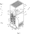
figure 1 est une vue schématique en perspective d'un dispositif de purification d'un milieu gazeux chargé de particules, conforme à la présente invention ; - la
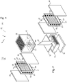
figure 2 est une vue éclatée, à échelle différente, des principaux éléments du dispositif de lafigure 1 ; - la
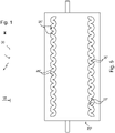
figure 3 est une vue en plan, schématique et à échelle différente, d'une structure émissive de ce dispositif ; - la
figure 4 est une vue schématique en perspective d'un support de structures émissives selon un autre mode de réalisation de la présente invention ; et - la
figure 5 est une vue en plan, schématique, d'une structure émissive selon un autre mode de réalisation de l'invention. - Le dispositif de purification 10 d'un milieu gazeux chargé de particules faisant l'objet du mode de réalisation des
figures 1 à 3 est un dispositif indépendant, qui peut être monté sur roulettes. Il a une configuration globale de parallélépipède rectangle. - Dans un souci de mise en évidence de ses éléments caractéristiques, ce dispositif de purification a été représenté de façon très schématique sur ces figures.
- L'assemblage de ses diverses pièces constitutives n'a en particulier pas été représenté dans le détail, car bien connu en soi de l'homme du métier.
- Ce dispositif de purification 10 comporte, d'une manière générale, une chambre de filtration électrostatique 11 et des moyens d'aspiration 12 en aval de cette chambre de filtration électrostatique, pour extraire de la chambre le milieu gazeux débarrassé de ses particules.
- En pratique, cette chambre de filtration électrostatique 11 est, ici, interposée entre un compartiment d'entrée 13 par lequel le milieu gazeux chargé de particules pénètre dans le dispositif et plus particulièrement dans la chambre de filtration électrostatique 11 et un compartiment de sortie 14, à la faveur duquel sont logés les moyens d'aspiration 12 et par lequel le milieu gazeux débarrassé de ses particules est rejeté dans le milieu environnant.
- Selon la configuration de parallépipède rectangle du dispositif de purification 10, le compartiment d'entrée 13 comporte un cadre 15 porté par un fond 16 et formé de quatre parois assemblées à angle droit dont l'une, 17, est perforée pour permettre au milieu gazeux d'entrer dans le dispositif, ici par le dessous de la chambre de filtration électrostatique 11.
- Dans le cas du présent mode de réalisation, le milieu gazeux chargé de particules pénètre ainsi dans le dispositif de purification 10, selon une direction sensiblement perpendiculaire à celle d'écoulement dans la chambre de filtration 11.
- Avant de pénétrer dans cette chambre de filtration électrostatique, il traverse, ici, un préfiltre 18 destiné à retenir les grosses particules. Il s'agit, par exemple, d'un filtre en tricot métallique ou en métal étiré.
- A l'extrémité opposée du dispositif de purification 10, le compartiment 14 de sortie du milieu gazeux débarrassé de ses particules comporte un caisson 19 en forme de parallépipède rectangle, dont la paroi supérieur 20 est perforée pour laisser passer ce milieu gazeux débarrassé de ses particules.
- Les moyens d'aspiration 12, qui se présentent ici sous la forme d'un ventilateur, sont montés dans ce caisson 19, au niveau de la face de celui-ci opposé à la paroi perforée 20.
- Le milieu gazeux s'écoule ainsi, horizontalement dans le caisson d'entrée 15 puis verticalement jusqu'à la sortie du dispositif de purification 10.
- Comme on peut le voir sur les
figures 1 et2 , les moyens d'aspiration 12 sont agencés directement à la sortie de la chambre de filtration électrostatique 11 et sont en communication fluidique avec celle-ci pour en aspirer le milieu gazeux. - Cette chambre de filtration électrostatique 11 comporte, ici, deux supports 21 de structures émissives agencés dans le passage que forme la chambre de filtration électrostatique 11 entre une entrée dans celle-ci (après le préfiltre 18) et une sortie de celle-ci (juste avant les moyens d'aspiration 12).
- De part et d'autre de ces supports 21 de structures émissives, sont agencées des structures collectrices 22 conçues pour piéger les particules contenues dans le milieu gazeux chargé de particules.
- Chaque support 21 de structures émissives comporte, plus précisément, une pluralité de structures émissives 23 agencées dans le passage, l'une à la suite de l'autre, entre l'entrée et la sortie de la chambre de filtration électrostatique 11.
- Chaque structure émissive 23 se présente sous la forme d'une plaque, de préférence d'une lame, ici au nombre de cinq par support 21, conçue pour forcer le milieu gazeux chargé de particules à s'écouler au voisinage des structures collectrices 22.
- Chaque lame 23 comporte par ailleurs, à sa périphérie, des pointes dirigées 26 vers les structures collectrices 22.
- Il s'agit, plus précisément, comme on le voit mieux sur la
figure 3 , d'une lame 23 présentant, de part et d'autre d'une surface centrale de déflexion 24, des échancrures 25 formant entre elles lesdites pointes 26. - Il s'agit, ici, d'échancrures arrondies découpées dans une plaque d'acier inoxydable de telle sorte à ce que les pointes des deux bords opposés de la lame 23 munis de ces pointes 26 soient disposées en quinconce.
- Chaque support 21 comporte deux profilés en U 27 assemblés, parallèlement l'un à l'autre et dos à dos, par quatre entretoises 28 soudées, chacune, à un coin du profilé en U 27. Il est à noter à cet égard que la quatrième entretoise 28 n'est pas visible sur les figures.
- Chaque lame 23 comporte, pour son montage sur ce support 21, une tige 29 soudée sur chacun de deux bords de montage opposés 30 qui s'étendent globalement perpendiculairement aux bords des lames 23 munies des pointes 26.
- Les profilés en U 27 sont pourvus, pour la réception des tiges 29, d'ouvertures de passage 31 de ces tiges .
- Le maintien en position sur le support 21 de chacune des lames est obtenu, dans le cas du présent mode de réalisation, au moyen de l'interposition d'un isolateur 32 emboité, par complémentarité de formes (de section carrée), dans une ouverture 31 et recevant, lui-même, une tige 29 de la lame 23.
- Chaque tige 29 est, pour ce faire, filetée et engagée dans un trou cylindrique central de l'isolateur 32 et fixée par un écrou (non visible sur les figures et logé dans un trou de passage 36 de section carrée précédant ce trou cylindrique dans l'isolateur et se terminant avant ce dernier trou par une surface d'appui pour l'écrou), de manière à ce que chaque lame soit montée avec possibilité d'orientation angulaire dans la chambre de filtration électrostatique 11.
- On notera, ici, que dans d'autres modes de réalisation, l'isolateur peut également être protégé au moyen d'une cloche et d'une contre-cloche ou de déflecteurs, à la manière de ce qui est décrit dans la demande de brevet citée ci-dessus (
WO 01/19525 - Chaque lame 23 formant une structure émissive est, ici, portée à une tension cathodique de l'ordre de 10 kV par un circuit fournissant une haute tension 33, logé dans un coffret de commande 34 monté, dans le cadre du présent mode de réalisation, dans le caisson 19.
- Pour le piégeage des particules, chaque structure collectrice 22 comporte, dans le cadre du présent mode de réalisation, un tricot métallique sous forme d'une plaque portée, ici, à une tension anodique de l'ordre de 5 kV, en étant relié à un circuit 35 fournissant une haute tension, qui est également logé dans le coffret de commande 34.
- Pour leur alimentation en haute tension, les plaques collectrices 22 peuvent être montées dans un cadre par l'intermédiaire de tiges traversant des ouvertures ménagées dans ce cadre et interposition d'isolateurs, d'une manière similaire de ce qui est prévu pour les lames 23 sur leur support 21. De ce fait, cela n'a pas été représenté sur les figures, dans un souci de simplification.
- On notera néanmoins que la liaison au circuit 35 peut-être obtenue par exemple avec une lame ressort solidaire du caisson supérieur 19 et en contact avec une tige de la plaque 22.La mise en œuvre d'une ou plusieurs de ces lames peut aussi permettre de maintenir la plaque en position au sein du dispositif et sa mise en place et son retrait de celui-ci.
- Dans le cas des plaques collectrices centrales 22, le maintien en place est assuré par leur agencement entre les deux supports 21 (leur mise en place et retrait est obtenu par simple coulissement).
- De telles dispositions ne sont pas représentées, dans un souci de simplification, sur les
figures 1 à 3 , mais peuvent être aisément mises en œuvre par l'homme du métier à partir des explications précitées. - Le dispositif de purification conforme à la présente invention, tel que décrit notamment en référence aux
figures 1 à 3 , s'avère ainsi particulièrement modulable, notamment grâce au montage des lames 23 sur les supports 21, l'une indépendamment de l'autre (et isolée électriquement l'une de l'autre sur leur support). Cela permet notamment d'orienter chacune des lames comme on le souhaite, en particulier pour produire de l'ozone ayant un effet germicide sur les micro-organismes du type virus et bactéries. Cette production d'ozone peut être obtenue en orientant les lames 23 perpendiculairement aux plaques collectrices 22 , tandis qu'une orientation différente de la perpendiculaire (on éloigne les pointes des structures collectrices 22) arrêtera ou diminuera cette production d'ozone. - Bien entendu, les lames 23 sont toujours orientées de telle sorte à former un angle non nul avec le plan des plaques collectrices 22 qui s'étendent parallèlement l'une à l'autre, les lames 23 étant elles-mêmes alignées suivant un alignement parallèle à ces mêmes plans.
- On notera encore que les bords des lames 23 pourvus des pointes 26, s'étendent jusqu'au voisinage des plaques collectrices 22, en ne laissant subsister qu'un espace évitant la formation d'arcs dans une position dans laquelle les lames 23 s'étendent perpendiculairement à ces plaques collectrices 22 soit, en pratique, un espace de l'ordre d'un millimètre pour 1000V de tension appliquée à la lame 23 correspondante.
- En outre, des ions négatifs produits par l'ionisation ayant lieu dans la chambre de filtration électrostatique sont également intéressants sur le plan des effets thérapeutiques qu'ils peuvent engendrer.
- On notera encore que la possibilité d'orienter les lames 23 permet de jouer avec la vitesse du flux gazeux s'écoulant dans la chambre de filtration électrostatique 11.
- Une porte 37 est, par ailleurs, prévue pour isoler les plaques collectrices 22 latérales du milieu environnant, tout en pouvant y accéder pour les retirer du dispositif de purification 10 en vue de leur nettoyage.
- Ce dispositif s'avère également aisé à fabriquer, par exemple à partir d'une découpe et, le cas échéant, d'un pliage de plaques d'acier inoxydable.
- Par ailleurs, un tel dispositif peut également être aisément mis en œuvre dans des systèmes déjà existants.
- Suivant une configuration inverse (il suffirait de retourner le ventilateur et déplacer le préfiltre 18), l'air à traiter pourrait être aspiré par le haut et être rejeté par le bas du dispositif. Une telle configuration trouverait avantageusement application dans les gaines de ventilation.
- Il peut être ajouté que le dispositif peut fonctionner verticalement, comme visible sur les
figures 1 à 3 , ou horizontalement. - Selon une autre possibilité (voir
figure 4 ), il peut être envisagé de mettre par exemple en œuvre deux rangées de structures émissives 23', ici des plaques, s'étendant côte à côte, de préférence parallèlement l'une à l'autre, dans le passage, avec une disposition en quinconce d'une rangée par rapport à l'autre. Un seul support 21' est par ailleurs prévu dans le cadre de ce mode de réalisation pour porter ces structures émissives 23'. - Selon encore un autre mode de réalisation des structures émissives 23", représenté sur la
figure 5 , les pointes 26" ne font pas saillie de la périphérie de chacune des plaques, mais sont formées à l'intérieur de la plaque correspondante, au moyen d'une découpe longitudinale pratiquée dans celle-ci au voisinage de chacun de ses bords longitudinaux. - Il s'agit plus précisément, de chaque côté de la plaque, d'une découpe formant deux rangées d'échancrures arrondies 25", se faisant face et formant entre elles les pointes 26" dirigées vers les structures collectrices. Chaque découpe est en outre formée de sorte à ce que les pointes 26" des deux rangées soient disposées en quinconce.
- Bien entendu, la présente invention ne se limite nullement aux modes de réalisation choisis et représentés, mais englobe toute variante à la portée de l'homme du métier.
- En particulier, le dispositif conforme à l'invention pourrait comporter une lampe à rayonnement UV agencée en amont de l'entrée de la chambre de filtration électrostatique 11 (par exemple dans le caisson 15) pour attirer et tuer des insectes, tels que des moustiques.
- A l'extrémité opposée, un filtre de finition, par exemple à base de charbon actif, en tricot métallique ou métal étiré, peut également être mis en œuvre entre la chambre de filtration électrostatique 11 et les moyens d'aspiration 12.
- Chaque structure collectrice peut par ailleurs comporter une ou une succession de plaques en métal étiré à la place du tricot métallique voire être réalisée à partir d'une alternance de tricot métallique et de plaques en métal étiré.
- D'autres tensions peuvent également être envisagées pour les structures émettrices et collectrices. En particulier, il peut être envisagé de porter, dans une succession de plaques de métal étiré formant structure collectrice, une plaque sur deux à une tension de l'ordre de 5 kV et de mettre la suivante à la masse. Généralement, les tensions sont choisies pour être comprise entre 10 et 50 kV.
- En fonction de la tension que l'on décide d'appliquer aux structures émissives et collectrices, le circuit fournissant une haute tension fournira bien entendu une haute tension positive ou négative.
- Une autre possibilité pourrait être de porter une structure émissive sur deux à une haute tension positive et l'autre à une haute tension négative, tandis que les structures collectrices seraient mises à la masse ou une haute tension positive.
- On notera, par ailleurs, qu'un bâti, réalisé à partir de profilés, tels que des cornières, peut venir compléter le dispositif, par exemple pour son montage sur roulettes ou la mise en place des plaques collectrices centrales sur des rails en forme de U en vue de faciliter leur coulissement.
- Bien plus de deux supports de structures émissives peuvent en outre être envisagés.
- En outre, chaque lame pourra, pour augmenter les turbulences au niveau du flux aspiré, être vrillée.
Claims (12)
- Dispositif de purification (10) d'un milieu gazeux chargé de particules, comportant une chambre de filtration électrostatique (11) ayant un passage pour le milieu gazeux chargé de particules qui s'étend entre une entrée de ce milieu dans la chambre (11) et une sortie de cette dernière ; une pluralité de structures émissives (23) agencées dans le passage, l'une à la suite de l'autre entre l'entrée et la sortie de la chambre (11); et, de part et d'autre de ces structures émissives (23), des structures collectrices (22) sous la forme de plaques pour collecter les particules ; chaque structure émissive (23) se présentant sous la forme d'une plaque comportant, à sa périphérie, des pointes (26) dirigées vers les structures collectrices (22); caractérisé en ce que chaque plaque des structures émissives (23) est conçue pour forcer le milieu gazeux chargé de particules à s'écouler au voisinage des structures collectrices (23); chaque structure collectrice (22) comporte, pour piéger les particules contenues dans le milieu gazeux chargé de particules, un tricot métallique et/ou une succession de plaques en métal étiré ; et le dispositif (10) comporte en outre des moyens d'aspiration (12) raccordés fluidiquement à la sortie de la chambre (11) pour extraire de la chambre (11) le milieu gazeux débarrassé de ses particules.
- Dispositif (10) selon la revendication 1, dans lequel l'une au moins des structures émissives (23) est montée orientable dans la chambre de filtration électrostatique (11).
- Dispositif (10) selon la revendication 1 ou 2, dans lequel chaque plaque des structures émissives (23) se présente sous la forme d'une lame pouvant être vrillée.
- Dispositif (10) selon l'une quelconque des revendications 1 à 3, dans lequel chaque plaque des structures émissives (23) présente, de part et d'autre d'une surface centrale de déflexion (24), des échancrures (25) formant entre elles lesdites pointes (26).
- Dispositif (10) selon la revendication 4, dans lequel les pointes (26) sont disposées en quinconce le long de deux bords opposés de chaque plaque des structures émissives (23).
- Dispositif (10) selon la revendication 4 ou 5, dans lequel les bords des plaques des structures émissives (23) pourvus des pointes (26) s'étendent jusqu'au voisinage des structures collectrices (22), en ne laissant subsister qu'un espace évitant la formation d'arcs, dans une position dans laquelle les plaques des structures émissives (23) s'étendent perpendiculairement aux structures collectrices (22), parallèles entre elles.
- Dispositif (10) selon l'une quelconque des revendications 1 à 6, dans lequel chaque plaque des structures émissives (23) comporte une tige (29) en saillie sur chacun de deux bords de montage opposés, pour le montage de la plaque des structures émissives (23) sur un support (21).
- Dispositif (10) selon la revendication 7, dans lequel le support (21) se présente sous la forme d'un cadre pourvu, pour la réception de chaque tige (29), d'une ouverture de passage de celle-ci.
- Dispositif (10) selon l'une quelconque des revendications 1 à 8, dans lequel chaque structure émissive (23) est portée à haute tension, de préférence à une tension de l'ordre de 10 kV.
- Dispositif (10) selon l'une quelconque des revendications 1 à 9, dans lequel chaque structure collectrice (22) est portée à haute tension, de préférence à une tension de l'ordre de 5 kV.
- Dispositif (10) selon l'une quelconque des revendications 1 à 10, dans lequel les structures émissives (23) sont alignées, suivant un alignement parallèle aux structures collectrices (22).
- Dispositif (10) selon l'une quelconque des revendications 1 à 11, dans lequel chaque structure collectrice (22) a une forme de parallépipède rectangle.
Applications Claiming Priority (2)
| Application Number | Priority Date | Filing Date | Title |
|---|---|---|---|
| FR1453065A FR3019474B1 (fr) | 2014-04-07 | 2014-04-07 | Dispositif de filtration |
| PCT/FR2015/050876 WO2015155449A1 (fr) | 2014-04-07 | 2015-04-03 | Dispositif de filtration |
Publications (2)
| Publication Number | Publication Date |
|---|---|
| EP3129151A1 EP3129151A1 (fr) | 2017-02-15 |
| EP3129151B1 true EP3129151B1 (fr) | 2022-11-23 |
Family
ID=51352545
Family Applications (1)
| Application Number | Title | Priority Date | Filing Date |
|---|---|---|---|
| EP15719801.1A Active EP3129151B1 (fr) | 2014-04-07 | 2015-04-03 | Dispositif de filtration |
Country Status (3)
| Country | Link |
|---|---|
| EP (1) | EP3129151B1 (fr) |
| FR (1) | FR3019474B1 (fr) |
| WO (1) | WO2015155449A1 (fr) |
Citations (2)
| Publication number | Priority date | Publication date | Assignee | Title |
|---|---|---|---|---|
| JPH0263560A (ja) * | 1988-08-30 | 1990-03-02 | Mitsubishi Heavy Ind Ltd | 除じん装置 |
| WO2014204310A1 (fr) * | 2013-06-19 | 2014-12-24 | Virus Free Air B.V. | Dispositif de nettoyage d'un écoulement de gaz |
Family Cites Families (6)
| Publication number | Priority date | Publication date | Assignee | Title |
|---|---|---|---|---|
| JPS58119355A (ja) * | 1981-12-30 | 1983-07-15 | Ono Kagaku Kikai Kk | 電気集じん装置 |
| JP3358008B2 (ja) * | 1994-01-31 | 2002-12-16 | 株式会社エルデック | 電気集塵装置 |
| FR2798303B1 (fr) | 1999-09-14 | 2001-11-09 | Daniel Teboul | Dispositif de traitement d'un milieu gazeux, en particulier des gaz d'echappement d'un moteur a combustion interne, et vehicule equipe d'un tel dispositif |
| CN1791468B (zh) * | 2003-08-29 | 2012-02-08 | 三菱重工业株式会社 | 集尘装置 |
| CN103025434A (zh) * | 2010-06-02 | 2013-04-03 | 三菱重工机电系统株式会社 | 集尘装置的运行方法以及集尘装置 |
| KR101199552B1 (ko) * | 2011-11-04 | 2012-11-12 | 서울특별시도시철도공사 | 허니컴대전부를 갖는 유도전압 전기집진장치 |
-
2014
- 2014-04-07 FR FR1453065A patent/FR3019474B1/fr not_active Expired - Fee Related
-
2015
- 2015-04-03 WO PCT/FR2015/050876 patent/WO2015155449A1/fr not_active Ceased
- 2015-04-03 EP EP15719801.1A patent/EP3129151B1/fr active Active
Patent Citations (2)
| Publication number | Priority date | Publication date | Assignee | Title |
|---|---|---|---|---|
| JPH0263560A (ja) * | 1988-08-30 | 1990-03-02 | Mitsubishi Heavy Ind Ltd | 除じん装置 |
| WO2014204310A1 (fr) * | 2013-06-19 | 2014-12-24 | Virus Free Air B.V. | Dispositif de nettoyage d'un écoulement de gaz |
Also Published As
| Publication number | Publication date |
|---|---|
| FR3019474B1 (fr) | 2019-08-02 |
| FR3019474A1 (fr) | 2015-10-09 |
| WO2015155449A1 (fr) | 2015-10-15 |
| EP3129151A1 (fr) | 2017-02-15 |
Similar Documents
| Publication | Publication Date | Title |
|---|---|---|
| EP2564933B1 (fr) | Dispositif de collecte électrostatique de particules en suspension dans un milieu gazeux | |
| CN107427839B (zh) | 用于分离污染物的设备和方法 | |
| RU2613654C1 (ru) | Установка для фильтрации микрочастиц, содержащихся в газообразных продуктах сгорания и/или отработавших газах, и соответствующий выпускной контур | |
| WO2009104411A1 (fr) | Collecteur de poussières | |
| EP3328548B1 (fr) | Methode et dispositif de collecte de particules d'aerosols, a collecte selective en fonction de la granulometrie des particules | |
| US10828646B2 (en) | Electrostatic air filter | |
| US20150075379A1 (en) | Filtration assembly | |
| FR2655882A1 (fr) | Dispositif pour epurer des gaz. | |
| KR20110135899A (ko) | 멀티크로스핀 이오나이저를 이용한 유도전압 전기집진장치 | |
| CN102209591A (zh) | 集尘装置 | |
| JP2009125653A (ja) | 空気浄化装置 | |
| EP3129151B1 (fr) | Dispositif de filtration | |
| JP2010022949A (ja) | 排ガス処理装置 | |
| KR101180035B1 (ko) | 멀티크로스핀 이오나이저를 이용한 유도전압 전기집진장치 | |
| WO2008107598A1 (fr) | Dispositif de filtre electrostatique pour la capture et la destruction de particules de suie contenues dans les gaz d'echappement d'un moteur a combustion | |
| EP2566526A1 (fr) | Ensemble de purification d'air par photocatalyse | |
| EP2954954B1 (fr) | Agencement de filtre à air | |
| US20240299954A1 (en) | High efficiency negative ionisation cell for fine particles, ultrafine particles and nanoparticles present at high and ultra-high density in fumes, in vehicle exhaust gases and in the air | |
| JP2010240578A (ja) | 集塵セル及びこれを用いたエアクリーナ | |
| EP0744996B1 (fr) | Echangeur cyclonique pour la purification et la depollution de l'air | |
| FR2717711A1 (fr) | Electrofiltre épurateur ioniseur en milieu gazeux, de grande puissance, à configuration de champ électrique de haute densité. | |
| FR2623424A1 (fr) | Dispositif et procede de filtrage electrostatique a filtre perpendiculaire a l'ecoulement de fluide gazeux, notamment de l'air | |
| JP2013086047A (ja) | イオン捕捉シート、イオン捕捉モジュールおよびクリーンエア供給装置 | |
| JP5561995B2 (ja) | 浮遊物濾過補足装置 | |
| FR3135900A1 (fr) | Dispositif ionique de traitement de l’air |
Legal Events
| Date | Code | Title | Description |
|---|---|---|---|
| STAA | Information on the status of an ep patent application or granted ep patent |
Free format text: STATUS: THE INTERNATIONAL PUBLICATION HAS BEEN MADE |
|
| PUAI | Public reference made under article 153(3) epc to a published international application that has entered the european phase |
Free format text: ORIGINAL CODE: 0009012 |
|
| STAA | Information on the status of an ep patent application or granted ep patent |
Free format text: STATUS: REQUEST FOR EXAMINATION WAS MADE |
|
| 17P | Request for examination filed |
Effective date: 20161107 |
|
| AK | Designated contracting states |
Kind code of ref document: A1 Designated state(s): AL AT BE BG CH CY CZ DE DK EE ES FI FR GB GR HR HU IE IS IT LI LT LU LV MC MK MT NL NO PL PT RO RS SE SI SK SM TR |
|
| AX | Request for extension of the european patent |
Extension state: BA ME |
|
| DAV | Request for validation of the european patent (deleted) | ||
| DAX | Request for extension of the european patent (deleted) | ||
| STAA | Information on the status of an ep patent application or granted ep patent |
Free format text: STATUS: EXAMINATION IS IN PROGRESS |
|
| 17Q | First examination report despatched |
Effective date: 20180525 |
|
| GRAP | Despatch of communication of intention to grant a patent |
Free format text: ORIGINAL CODE: EPIDOSNIGR1 |
|
| STAA | Information on the status of an ep patent application or granted ep patent |
Free format text: STATUS: GRANT OF PATENT IS INTENDED |
|
| RIC1 | Information provided on ipc code assigned before grant |
Ipc: B03C 3/47 20060101ALI20211206BHEP Ipc: B03C 3/41 20060101ALI20211206BHEP Ipc: B03C 3/36 20060101ALI20211206BHEP Ipc: B03C 3/011 20060101ALI20211206BHEP Ipc: B03C 3/155 20060101ALI20211206BHEP Ipc: B03C 3/09 20060101ALI20211206BHEP Ipc: B03C 3/08 20060101ALI20211206BHEP Ipc: B03C 3/32 20060101AFI20211206BHEP |
|
| INTG | Intention to grant announced |
Effective date: 20211223 |
|
| GRAS | Grant fee paid |
Free format text: ORIGINAL CODE: EPIDOSNIGR3 |
|
| GRAA | (expected) grant |
Free format text: ORIGINAL CODE: 0009210 |
|
| STAA | Information on the status of an ep patent application or granted ep patent |
Free format text: STATUS: THE PATENT HAS BEEN GRANTED |
|
| AK | Designated contracting states |
Kind code of ref document: B1 Designated state(s): AL AT BE BG CH CY CZ DE DK EE ES FI FR GB GR HR HU IE IS IT LI LT LU LV MC MK MT NL NO PL PT RO RS SE SI SK SM TR |
|
| REG | Reference to a national code |
Ref country code: GB Ref legal event code: FG4D Free format text: NOT ENGLISH |
|
| REG | Reference to a national code |
Ref country code: CH Ref legal event code: EP |
|
| REG | Reference to a national code |
Ref country code: AT Ref legal event code: REF Ref document number: 1532813 Country of ref document: AT Kind code of ref document: T Effective date: 20221215 Ref country code: DE Ref legal event code: R096 Ref document number: 602015081670 Country of ref document: DE |
|
| REG | Reference to a national code |
Ref country code: IE Ref legal event code: FG4D Free format text: LANGUAGE OF EP DOCUMENT: FRENCH |
|
| REG | Reference to a national code |
Ref country code: LT Ref legal event code: MG9D |
|
| REG | Reference to a national code |
Ref country code: NL Ref legal event code: MP Effective date: 20221123 |
|
| REG | Reference to a national code |
Ref country code: AT Ref legal event code: MK05 Ref document number: 1532813 Country of ref document: AT Kind code of ref document: T Effective date: 20221123 |
|
| PG25 | Lapsed in a contracting state [announced via postgrant information from national office to epo] |
Ref country code: SE Free format text: LAPSE BECAUSE OF FAILURE TO SUBMIT A TRANSLATION OF THE DESCRIPTION OR TO PAY THE FEE WITHIN THE PRESCRIBED TIME-LIMIT Effective date: 20221123 Ref country code: PT Free format text: LAPSE BECAUSE OF FAILURE TO SUBMIT A TRANSLATION OF THE DESCRIPTION OR TO PAY THE FEE WITHIN THE PRESCRIBED TIME-LIMIT Effective date: 20230323 Ref country code: NO Free format text: LAPSE BECAUSE OF FAILURE TO SUBMIT A TRANSLATION OF THE DESCRIPTION OR TO PAY THE FEE WITHIN THE PRESCRIBED TIME-LIMIT Effective date: 20230223 Ref country code: LT Free format text: LAPSE BECAUSE OF FAILURE TO SUBMIT A TRANSLATION OF THE DESCRIPTION OR TO PAY THE FEE WITHIN THE PRESCRIBED TIME-LIMIT Effective date: 20221123 Ref country code: FI Free format text: LAPSE BECAUSE OF FAILURE TO SUBMIT A TRANSLATION OF THE DESCRIPTION OR TO PAY THE FEE WITHIN THE PRESCRIBED TIME-LIMIT Effective date: 20221123 Ref country code: ES Free format text: LAPSE BECAUSE OF FAILURE TO SUBMIT A TRANSLATION OF THE DESCRIPTION OR TO PAY THE FEE WITHIN THE PRESCRIBED TIME-LIMIT Effective date: 20221123 Ref country code: AT Free format text: LAPSE BECAUSE OF FAILURE TO SUBMIT A TRANSLATION OF THE DESCRIPTION OR TO PAY THE FEE WITHIN THE PRESCRIBED TIME-LIMIT Effective date: 20221123 |
|
| PG25 | Lapsed in a contracting state [announced via postgrant information from national office to epo] |
Ref country code: RS Free format text: LAPSE BECAUSE OF FAILURE TO SUBMIT A TRANSLATION OF THE DESCRIPTION OR TO PAY THE FEE WITHIN THE PRESCRIBED TIME-LIMIT Effective date: 20221123 Ref country code: PL Free format text: LAPSE BECAUSE OF FAILURE TO SUBMIT A TRANSLATION OF THE DESCRIPTION OR TO PAY THE FEE WITHIN THE PRESCRIBED TIME-LIMIT Effective date: 20221123 Ref country code: LV Free format text: LAPSE BECAUSE OF FAILURE TO SUBMIT A TRANSLATION OF THE DESCRIPTION OR TO PAY THE FEE WITHIN THE PRESCRIBED TIME-LIMIT Effective date: 20221123 Ref country code: IS Free format text: LAPSE BECAUSE OF FAILURE TO SUBMIT A TRANSLATION OF THE DESCRIPTION OR TO PAY THE FEE WITHIN THE PRESCRIBED TIME-LIMIT Effective date: 20230323 Ref country code: HR Free format text: LAPSE BECAUSE OF FAILURE TO SUBMIT A TRANSLATION OF THE DESCRIPTION OR TO PAY THE FEE WITHIN THE PRESCRIBED TIME-LIMIT Effective date: 20221123 Ref country code: GR Free format text: LAPSE BECAUSE OF FAILURE TO SUBMIT A TRANSLATION OF THE DESCRIPTION OR TO PAY THE FEE WITHIN THE PRESCRIBED TIME-LIMIT Effective date: 20230224 |
|
| PG25 | Lapsed in a contracting state [announced via postgrant information from national office to epo] |
Ref country code: NL Free format text: LAPSE BECAUSE OF FAILURE TO SUBMIT A TRANSLATION OF THE DESCRIPTION OR TO PAY THE FEE WITHIN THE PRESCRIBED TIME-LIMIT Effective date: 20221123 |
|
| PG25 | Lapsed in a contracting state [announced via postgrant information from national office to epo] |
Ref country code: SM Free format text: LAPSE BECAUSE OF FAILURE TO SUBMIT A TRANSLATION OF THE DESCRIPTION OR TO PAY THE FEE WITHIN THE PRESCRIBED TIME-LIMIT Effective date: 20221123 Ref country code: RO Free format text: LAPSE BECAUSE OF FAILURE TO SUBMIT A TRANSLATION OF THE DESCRIPTION OR TO PAY THE FEE WITHIN THE PRESCRIBED TIME-LIMIT Effective date: 20221123 Ref country code: EE Free format text: LAPSE BECAUSE OF FAILURE TO SUBMIT A TRANSLATION OF THE DESCRIPTION OR TO PAY THE FEE WITHIN THE PRESCRIBED TIME-LIMIT Effective date: 20221123 Ref country code: DK Free format text: LAPSE BECAUSE OF FAILURE TO SUBMIT A TRANSLATION OF THE DESCRIPTION OR TO PAY THE FEE WITHIN THE PRESCRIBED TIME-LIMIT Effective date: 20221123 Ref country code: CZ Free format text: LAPSE BECAUSE OF FAILURE TO SUBMIT A TRANSLATION OF THE DESCRIPTION OR TO PAY THE FEE WITHIN THE PRESCRIBED TIME-LIMIT Effective date: 20221123 |
|
| REG | Reference to a national code |
Ref country code: DE Ref legal event code: R097 Ref document number: 602015081670 Country of ref document: DE |
|
| PG25 | Lapsed in a contracting state [announced via postgrant information from national office to epo] |
Ref country code: SK Free format text: LAPSE BECAUSE OF FAILURE TO SUBMIT A TRANSLATION OF THE DESCRIPTION OR TO PAY THE FEE WITHIN THE PRESCRIBED TIME-LIMIT Effective date: 20221123 Ref country code: AL Free format text: LAPSE BECAUSE OF FAILURE TO SUBMIT A TRANSLATION OF THE DESCRIPTION OR TO PAY THE FEE WITHIN THE PRESCRIBED TIME-LIMIT Effective date: 20221123 |
|
| PLBE | No opposition filed within time limit |
Free format text: ORIGINAL CODE: 0009261 |
|
| STAA | Information on the status of an ep patent application or granted ep patent |
Free format text: STATUS: NO OPPOSITION FILED WITHIN TIME LIMIT |
|
| 26N | No opposition filed |
Effective date: 20230824 |
|
| REG | Reference to a national code |
Ref country code: DE Ref legal event code: R119 Ref document number: 602015081670 Country of ref document: DE |
|
| PG25 | Lapsed in a contracting state [announced via postgrant information from national office to epo] |
Ref country code: SI Free format text: LAPSE BECAUSE OF FAILURE TO SUBMIT A TRANSLATION OF THE DESCRIPTION OR TO PAY THE FEE WITHIN THE PRESCRIBED TIME-LIMIT Effective date: 20221123 |
|
| REG | Reference to a national code |
Ref country code: CH Ref legal event code: PL |
|
| GBPC | Gb: european patent ceased through non-payment of renewal fee |
Effective date: 20230403 |
|
| PG25 | Lapsed in a contracting state [announced via postgrant information from national office to epo] |
Ref country code: LU Free format text: LAPSE BECAUSE OF NON-PAYMENT OF DUE FEES Effective date: 20230403 |
|
| REG | Reference to a national code |
Ref country code: BE Ref legal event code: MM Effective date: 20230430 |
|
| PG25 | Lapsed in a contracting state [announced via postgrant information from national office to epo] |
Ref country code: MC Free format text: LAPSE BECAUSE OF FAILURE TO SUBMIT A TRANSLATION OF THE DESCRIPTION OR TO PAY THE FEE WITHIN THE PRESCRIBED TIME-LIMIT Effective date: 20221123 |
|
| PG25 | Lapsed in a contracting state [announced via postgrant information from national office to epo] |
Ref country code: GB Free format text: LAPSE BECAUSE OF NON-PAYMENT OF DUE FEES Effective date: 20230403 |
|
| PG25 | Lapsed in a contracting state [announced via postgrant information from national office to epo] |
Ref country code: MC Free format text: LAPSE BECAUSE OF FAILURE TO SUBMIT A TRANSLATION OF THE DESCRIPTION OR TO PAY THE FEE WITHIN THE PRESCRIBED TIME-LIMIT Effective date: 20221123 Ref country code: LI Free format text: LAPSE BECAUSE OF NON-PAYMENT OF DUE FEES Effective date: 20230430 Ref country code: GB Free format text: LAPSE BECAUSE OF NON-PAYMENT OF DUE FEES Effective date: 20230403 Ref country code: FR Free format text: LAPSE BECAUSE OF NON-PAYMENT OF DUE FEES Effective date: 20230430 Ref country code: DE Free format text: LAPSE BECAUSE OF NON-PAYMENT OF DUE FEES Effective date: 20231103 Ref country code: CH Free format text: LAPSE BECAUSE OF NON-PAYMENT OF DUE FEES Effective date: 20230430 |
|
| REG | Reference to a national code |
Ref country code: IE Ref legal event code: MM4A |
|
| PG25 | Lapsed in a contracting state [announced via postgrant information from national office to epo] |
Ref country code: BE Free format text: LAPSE BECAUSE OF NON-PAYMENT OF DUE FEES Effective date: 20230430 |
|
| PG25 | Lapsed in a contracting state [announced via postgrant information from national office to epo] |
Ref country code: IE Free format text: LAPSE BECAUSE OF NON-PAYMENT OF DUE FEES Effective date: 20230403 |
|
| PG25 | Lapsed in a contracting state [announced via postgrant information from national office to epo] |
Ref country code: IE Free format text: LAPSE BECAUSE OF NON-PAYMENT OF DUE FEES Effective date: 20230403 |
|
| PG25 | Lapsed in a contracting state [announced via postgrant information from national office to epo] |
Ref country code: IT Free format text: LAPSE BECAUSE OF FAILURE TO SUBMIT A TRANSLATION OF THE DESCRIPTION OR TO PAY THE FEE WITHIN THE PRESCRIBED TIME-LIMIT Effective date: 20221123 |
|
| PG25 | Lapsed in a contracting state [announced via postgrant information from national office to epo] |
Ref country code: FR Free format text: LAPSE BECAUSE OF NON-PAYMENT OF DUE FEES Effective date: 20230430 |
|
| PGRI | Patent reinstated in contracting state [announced from national office to epo] |
Ref country code: FR Effective date: 20240613 |
|
| PGFP | Annual fee paid to national office [announced via postgrant information from national office to epo] |
Ref country code: FR Payment date: 20240830 Year of fee payment: 10 |
|
| PG25 | Lapsed in a contracting state [announced via postgrant information from national office to epo] |
Ref country code: BG Free format text: LAPSE BECAUSE OF FAILURE TO SUBMIT A TRANSLATION OF THE DESCRIPTION OR TO PAY THE FEE WITHIN THE PRESCRIBED TIME-LIMIT Effective date: 20221123 |
|
| PG25 | Lapsed in a contracting state [announced via postgrant information from national office to epo] |
Ref country code: BG Free format text: LAPSE BECAUSE OF FAILURE TO SUBMIT A TRANSLATION OF THE DESCRIPTION OR TO PAY THE FEE WITHIN THE PRESCRIBED TIME-LIMIT Effective date: 20221123 |
|
| PG25 | Lapsed in a contracting state [announced via postgrant information from national office to epo] |
Ref country code: CY Free format text: LAPSE BECAUSE OF FAILURE TO SUBMIT A TRANSLATION OF THE DESCRIPTION OR TO PAY THE FEE WITHIN THE PRESCRIBED TIME-LIMIT; INVALID AB INITIO Effective date: 20150403 |
|
| PG25 | Lapsed in a contracting state [announced via postgrant information from national office to epo] |
Ref country code: HU Free format text: LAPSE BECAUSE OF FAILURE TO SUBMIT A TRANSLATION OF THE DESCRIPTION OR TO PAY THE FEE WITHIN THE PRESCRIBED TIME-LIMIT; INVALID AB INITIO Effective date: 20150403 |
|
| PG25 | Lapsed in a contracting state [announced via postgrant information from national office to epo] |
Ref country code: TR Free format text: LAPSE BECAUSE OF FAILURE TO SUBMIT A TRANSLATION OF THE DESCRIPTION OR TO PAY THE FEE WITHIN THE PRESCRIBED TIME-LIMIT Effective date: 20221123 |
|
| PG25 | Lapsed in a contracting state [announced via postgrant information from national office to epo] |
Ref country code: FR Free format text: LAPSE BECAUSE OF NON-PAYMENT OF DUE FEES Effective date: 20250430 |