EP3129676B1 - Verbesserte greifvorrichtung - Google Patents
Verbesserte greifvorrichtung Download PDFInfo
- Publication number
- EP3129676B1 EP3129676B1 EP15722740.6A EP15722740A EP3129676B1 EP 3129676 B1 EP3129676 B1 EP 3129676B1 EP 15722740 A EP15722740 A EP 15722740A EP 3129676 B1 EP3129676 B1 EP 3129676B1
- Authority
- EP
- European Patent Office
- Prior art keywords
- gripping device
- gripping
- longitudinal axis
- angle
- opening
- Prior art date
- Legal status (The legal status is an assumption and is not a legal conclusion. Google has not performed a legal analysis and makes no representation as to the accuracy of the status listed.)
- Not-in-force
Links
Images
Classifications
-
- F—MECHANICAL ENGINEERING; LIGHTING; HEATING; WEAPONS; BLASTING
- F16—ENGINEERING ELEMENTS AND UNITS; GENERAL MEASURES FOR PRODUCING AND MAINTAINING EFFECTIVE FUNCTIONING OF MACHINES OR INSTALLATIONS; THERMAL INSULATION IN GENERAL
- F16G—BELTS, CABLES, OR ROPES, PREDOMINANTLY USED FOR DRIVING PURPOSES; CHAINS; FITTINGS PREDOMINANTLY USED THEREFOR
- F16G11/00—Means for fastening cables or ropes to one another or to other objects; Caps or sleeves for fixing on cables or ropes
- F16G11/10—Quick-acting fastenings; Clamps holding in one direction only
- F16G11/105—Clamps holding in one direction only
- F16G11/108—Clamps holding in one direction only using a ball or a cylinder
-
- F—MECHANICAL ENGINEERING; LIGHTING; HEATING; WEAPONS; BLASTING
- F16—ENGINEERING ELEMENTS AND UNITS; GENERAL MEASURES FOR PRODUCING AND MAINTAINING EFFECTIVE FUNCTIONING OF MACHINES OR INSTALLATIONS; THERMAL INSULATION IN GENERAL
- F16G—BELTS, CABLES, OR ROPES, PREDOMINANTLY USED FOR DRIVING PURPOSES; CHAINS; FITTINGS PREDOMINANTLY USED THEREFOR
- F16G11/00—Means for fastening cables or ropes to one another or to other objects; Caps or sleeves for fixing on cables or ropes
- F16G11/04—Means for fastening cables or ropes to one another or to other objects; Caps or sleeves for fixing on cables or ropes with wedging action, e.g. friction clamps
- F16G11/044—Means for fastening cables or ropes to one another or to other objects; Caps or sleeves for fixing on cables or ropes with wedging action, e.g. friction clamps friction clamps deforming the cable, wire, rope or cord
- F16G11/048—Means for fastening cables or ropes to one another or to other objects; Caps or sleeves for fixing on cables or ropes with wedging action, e.g. friction clamps friction clamps deforming the cable, wire, rope or cord by moving a surface into the cable
-
- F—MECHANICAL ENGINEERING; LIGHTING; HEATING; WEAPONS; BLASTING
- F16—ENGINEERING ELEMENTS AND UNITS; GENERAL MEASURES FOR PRODUCING AND MAINTAINING EFFECTIVE FUNCTIONING OF MACHINES OR INSTALLATIONS; THERMAL INSULATION IN GENERAL
- F16G—BELTS, CABLES, OR ROPES, PREDOMINANTLY USED FOR DRIVING PURPOSES; CHAINS; FITTINGS PREDOMINANTLY USED THEREFOR
- F16G11/00—Means for fastening cables or ropes to one another or to other objects; Caps or sleeves for fixing on cables or ropes
- F16G11/10—Quick-acting fastenings; Clamps holding in one direction only
-
- F—MECHANICAL ENGINEERING; LIGHTING; HEATING; WEAPONS; BLASTING
- F16—ENGINEERING ELEMENTS AND UNITS; GENERAL MEASURES FOR PRODUCING AND MAINTAINING EFFECTIVE FUNCTIONING OF MACHINES OR INSTALLATIONS; THERMAL INSULATION IN GENERAL
- F16G—BELTS, CABLES, OR ROPES, PREDOMINANTLY USED FOR DRIVING PURPOSES; CHAINS; FITTINGS PREDOMINANTLY USED THEREFOR
- F16G11/00—Means for fastening cables or ropes to one another or to other objects; Caps or sleeves for fixing on cables or ropes
- F16G11/10—Quick-acting fastenings; Clamps holding in one direction only
- F16G11/105—Clamps holding in one direction only
- F16G11/106—Clamps holding in one direction only using a toothed surface
-
- F—MECHANICAL ENGINEERING; LIGHTING; HEATING; WEAPONS; BLASTING
- F16—ENGINEERING ELEMENTS AND UNITS; GENERAL MEASURES FOR PRODUCING AND MAINTAINING EFFECTIVE FUNCTIONING OF MACHINES OR INSTALLATIONS; THERMAL INSULATION IN GENERAL
- F16M—FRAMES, CASINGS OR BEDS OF ENGINES, MACHINES OR APPARATUS, NOT SPECIFIC TO ENGINES, MACHINES OR APPARATUS PROVIDED FOR ELSEWHERE; STANDS; SUPPORTS
- F16M13/00—Other supports for positioning apparatus or articles; Means for steadying hand-held apparatus or articles
- F16M13/02—Other supports for positioning apparatus or articles; Means for steadying hand-held apparatus or articles for supporting on, or attaching to, an object, e.g. tree, gate, window-frame, cycle
- F16M13/027—Ceiling supports
-
- Y—GENERAL TAGGING OF NEW TECHNOLOGICAL DEVELOPMENTS; GENERAL TAGGING OF CROSS-SECTIONAL TECHNOLOGIES SPANNING OVER SEVERAL SECTIONS OF THE IPC; TECHNICAL SUBJECTS COVERED BY FORMER USPC CROSS-REFERENCE ART COLLECTIONS [XRACs] AND DIGESTS
- Y10—TECHNICAL SUBJECTS COVERED BY FORMER USPC
- Y10T—TECHNICAL SUBJECTS COVERED BY FORMER US CLASSIFICATION
- Y10T24/00—Buckles, buttons, clasps, etc.
- Y10T24/39—Cord and rope holders
- Y10T24/3969—Sliding part or wedge
Definitions
- the present invention relates to a gripping device, and in particular to a device for gripping an elongate strand of material such as a wire.
- Gripping devices are used in many applications. For example, joining together wire strands in fencing applications, to suspend an object from a wire, to suspend sports equipment, or to suspend objects from structural elements of a building.
- Gripping devices are known from the patent documents referred to below: GB 2210517 , WO 95/30844 and WO 97/36123 describe examples of wire gripping devices in which toothed wedges grip the wire.
- GB2240581 describes a gripping device of the type described in the above-mentioned patents where the toothed wedges are replaced by ribbed wheels.
- WO 92/12766 describes a gripping device for gripping a cord which supports a ball.
- GB2378213 describes a wire connector device for connecting an electric fence wire to a post in which wedging means grip the wire.
- US 4,889,320 discloses a gripping device according to the preamble of claim 1.
- One problem associated with the known gripping devices is that when placed under excess load, or if the gripping device is defective, the gripped elongate element can pull throguh the gripping device. Obviously, this is undesirable and could have disastrous consequences.
- a gripping device comprising body having a longitudinal axis and including at least one elongate opening for receiving an elongate element, a gripping element, and means for bringing the gripping element into engagement with an elongate element located in the said opening, wherein the gripping element is mounted for translational movement in a slot having a longitudinal axis, and the longitudinal axis of the slot is set at an acute angle to the longitudinal axis of the opening, and wherein a force component exerted on an elongate element located in the said opening causes the gripping element to move in the slot and towards the elongate element, and wherein said opening is defined by walls and wherein one of the walls includes two intersecting surfaces lying at an angle to one another, the angle between the two surfaces being concave.
- the angle between the two surfaces lies in the range 160 to 179 degrees.
- one of the surfaces lies at an angle in the range 1 to 10 degrees with respect to a longitudinal axis of the body.
- both of the surfaces lie in the range 91 to 100 degrees with respect to an axis perpendicular to the longitudinal axis of the body.
- one of the surfaces lies at an angle in the range 3 to 8 degrees with respect to the longitudinal axis of the body.
- the other of the surfaces lies at an angle in the range 1 to 10 degrees with respect to the longitudinal axis of the body.
- the slot has ends and the surfaces intersect at a position aligned between the ends of the slot.
- the gripping element is advantageously a pinion wheel.
- a surface of the opening provides a track, the pinion wheel engaging with the track.
- the pinion wheel is one of: smooth, toothed and roughened.
- the track is one of: smooth, roughened and toothed.
- the gripping device may further comprise biasing means arranged to bias the pinion into the path of the elongate opening.
- the biasing means may be a spring, which spring may be a compression spring.
- the gripping element pushes an elongate element therein against an opposing wall.
- the wire is caused to bend slightly. This is sufficient to increase the surface area available for engagment with the gripping element.
- the gripping element of the invention is therefore better able to support heavy loads.
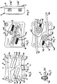
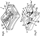
- the gripping device 1 comprises a body 2 and a top plate 3.
- the body 2 includes a pair of spaced apart openings 4 that extend through the body 2 from the front to the back of the device.
- Each opening 4 has a first side 4a and a second side 4b including a recess 4c.
- the recess 4c includes a track 4d.
- Within the boundary of each recess 4c and located in the body 2 a slot 4e is provided which is aligned with a corresponding slot 4e' in the top plate 3.
- a toothed pinion wheel 5 is mounted on a pin 5a having ends 5a' and 5a".
- the end 5a' of the pin 5a locates in the slot 4e, the end 5a" extending through the slot 4e' and providing a means by which the position of the pinion 5 may be manually adjusted.
- the shape of the aligned slots 4e, 4e' define a path in which the pin 5a travels.
- the slots 4e, 4e' are positioned and oriented such that the teeth of the pinion wheel 5 engage with the track 4d of the recess 4c, the ends of the slots 4e, 4e' defining the extreme positions of the pinion wheel.
- the slots 4e, 4e' lie substantially parallel with the track 4d, which is set and angle ⁇ to the longitudinal axis X-X of the body 2.
- the side 4a of the opening 4 includes two surfaces 4a' and 4a".
- the surfaces 4a', 4a" intersect and lie at an angle to one another, preferably between 160 and 179 degrees.
- a wire 20, as shown in Figure 4 may be introduced into the part of the opening including surface 4a' so as to exit through the opening through the part including surface 4a". Using this method, the end of the wire 20 pushes the pinion wheel 5 so that it travels along the path of the slot 4e', thereby allowing space for the wire to pass the pinion wheel and exit through the opening 4a".
- the surface 4a' lies at an angle ⁇ to an axis Y-Y lying perpendicular to the longitudinal axis of the device, the angle ⁇ being 94 degrees.
- the surface 4a" lies at an angle ⁇ to the axis Y-Y, which in the illustrated embodiment is also 94 degrees.
- the aforementioned angle need not be 94 degrees but the combination of the angles at which the surfaces 4a', 4a" lie must to be sufficient to cause an elongate element inserted through the opening 4 to bend as it passes around the pinion 5. Conversely, the combination of angles must not be so great as to limit the ability of the elongate element to be fed through the opening 4 from one end thereof. These two factors set the limits of the range of angles at which the surfaces 4a, 4a" may lie.
- each of the surfaces 4a' and 4a" lie on an angle of between 91 and 100 degrees to the axis Y-Y. It is not essential that each surface 4a', 4a" should lie on the same angle.
- the part 4a' may lie on a shallower angle than the part 4a" or vice versa. It is preferred that both angles lying within the range 91 to 100 degrees to the axis Y-Y, but one of the surfaces may lie outside the range, for example at 90 degrees to the axis Y-Y What is essential is that the surfaces 4a' and 4a" lie at an angle to one another, thereby causing an elongate element passing through the opening to bend slightly.
- the effect of such slight bending of the the elongate element is to increase the surface area thereof that is available for engagement with the pinion wheel 5.
- the body 2 includes a wall 4f forming one of the boundaries to the recess 4c.
- a compression spring sits partially in the slot 4e, its opposing ends engaging the wall 4f and the part 5a" of the pin 5a of pinion wheel 5.
- the spring 6 biases the pinion wheel 5 to a closed position, i.e. the position occupied by the pinion wheel in Figure 5 .
- the body 2 and top cover 3 are each formed of pressed steel.
- the body 2 includes holes 10 which align with correspondingly threaded holes (not shown) in the top cover 3. A screw is passed through the aligned holes to secure the body 2 and top cover 3 together.
- the body 2 also includes location pins 11 which align with bores 10' in the top cover. The dimensions of the said bores and location pins are such that one is a press fit into the other.
- the track 4d also includes a curved portion 4d 1 , the curve extending from one side of the opening 4 to the end of the substantially straight part of the track 4d.
- the action of the curve is to move the pinion wheel 5 towards the surface 4a' more rapidly over a unit of distance that is the case for the substantially straight part of the rack 4d.
- This movement of the pinion wheel 5 more rapidly towards the surface 4a' is provided for within the play between the pin 5a and the slots 4e, 4e'.
- the provision of the curve portion 4d 1 allows the gripping device of the invention to be used with a wide range of cross-setions of elongate elements. Nevertheless, the dimensions of the gripping device may be optimised to match particular cross-sectional dimensions of elongate elements.
- the track 4d may be smooth, roughened or toothed. In the illustrated embodiments, the track 4d is smooth.
Landscapes
- Engineering & Computer Science (AREA)
- General Engineering & Computer Science (AREA)
- Mechanical Engineering (AREA)
- Manipulator (AREA)
Claims (14)
- Greifvorrichtung (1), umfassend ein Gehäuse (2) mit einer Längsachse und wenigstens einer länglichen Öffnung (4) zum Aufnehmen eines länglichen Elements (20), ein Greifelement (5) und Mittel zum Ineingriffbringen des Greifelements (5) mit einem in der Öffnung (4) befindlichen länglichen Element (20), wobei das Greifelement (5) für eine Translationsbewegung in einem Schlitz (4e, 4e') mit einer Längsachse montiert ist und die Längsachse des Schlitzes einen spitzen Winkel zur Längsachse der Öffnung (4) hat, und wobei eine Kraftkomponente, die auf ein in der Öffnung (4) befindliches längliches Element (20) ausgeübt wird, bewirkt, dass sich das Greifelement (5) im Schlitz (4e, 4e') und in Richtung des länglichen Elements (2) bewegt, und wobei die Öffnung (4) durch Wände definiert wird und wobei eine der Wände (4a) zwei sich schneidende Oberflächen (4a', 4a") aufweist, die in einem festen Winkel zueinander liegen, dadurch gekennzeichnet, dass der Winkel zwischen den zwei Oberflächen konkav ist.
- Greifvorrichtung (1) nach Anspruch 1, wobei der Winkel zwischen den zwei Oberflächen (4a', 4a") im Bereich von 160 bis 179 Grad liegt.
- Greifvorrichtung (1) nach Anspruch 1 oder 2, wobei eine der Oberflächen einen Winkel im Bereich von 1 bis 10 Grad mit Bezug auf eine Längsachse des Gehäuses (2) bildet.
- Greifvorrichtung (1) nach Anspruch 3, wobei beide Oberflächen im Bereich von 91 bis 100 Grad mit Bezug auf eine Achse lotrecht zur Längsachse des Gehäuses (2) liegen.
- Greifvorrichtung (1) nach Anspruch 1, wobei eine der Oberflächen einen Winkel im Bereich von 3 bis 8 Grad mit Bezug auf die Längsachse des Gehäuses (2) bildet.
- Greifvorrichtung (1) nach Anspruch 5, wobei die andere der Oberflächen einen Winkel im Bereich von 1 bis 10 Grad mit Bezug auf die Längsachse des Gehäuses (2) bildet.
- Greifvorrichtung (1) nach einem vorherigen Anspruch, wobei der Schlitz (4e, 4e') Enden hat und die Oberflächen (4a', 4a") sich in einer zwischen den Enden des Schlitzes (4e, 4e') ausgerichteten Position schneiden.
- Greifvorrichtung (1) nach einem vorherigen Anspruch, wobei das Greifelement (5) ein Ritzelrad ist.
- Greifvorrichtung (1) nach Anspruch 7, wobei eine Oberfläche der Öffnung eine Spur (4d) bildet, wobei das Ritzelrad (5) in die Spur (4d) eingreift.
- Greifvorrichtung (1) nach Anspruch 8, wobei das Ritzelrad (5) glatt, gezahnt oder aufgeraut ist.
- Greifvorrichtung (1) nach Anspruch 9, wobei die Spur (4d) glatt, aufgeraut oder gezahnt ist.
- Greifvorrichtung (1) nach einem vorherigen Anspruch, das ferner Vorspannmittel (6) umfasst, ausgelegt zum Vorspannen des Ritzels (5) in den Pfad der länglichen Öffnung (4).
- Greifvorrichtung (1) nach Anspruch 12, wobei das Vorspannmittel (6) eine Feder ist.
- Greifvorrichtung (1) nach Anspruch 13, wobei die Feder eine Druckfeder ist.
Priority Applications (1)
| Application Number | Priority Date | Filing Date | Title |
|---|---|---|---|
| PL15722740T PL3129676T3 (pl) | 2014-04-07 | 2015-04-07 | Ulepszone urządzenie chwytające |
Applications Claiming Priority (2)
| Application Number | Priority Date | Filing Date | Title |
|---|---|---|---|
| GB1406207.9A GB2524964A (en) | 2014-04-07 | 2014-04-07 | Improved gripping device |
| PCT/GB2015/051059 WO2015155516A1 (en) | 2014-04-07 | 2015-04-07 | Improved gripping device |
Publications (2)
| Publication Number | Publication Date |
|---|---|
| EP3129676A1 EP3129676A1 (de) | 2017-02-15 |
| EP3129676B1 true EP3129676B1 (de) | 2018-09-19 |
Family
ID=50776919
Family Applications (1)
| Application Number | Title | Priority Date | Filing Date |
|---|---|---|---|
| EP15722740.6A Not-in-force EP3129676B1 (de) | 2014-04-07 | 2015-04-07 | Verbesserte greifvorrichtung |
Country Status (5)
| Country | Link |
|---|---|
| US (1) | US9453555B2 (de) |
| EP (1) | EP3129676B1 (de) |
| GB (1) | GB2524964A (de) |
| PL (1) | PL3129676T3 (de) |
| WO (1) | WO2015155516A1 (de) |
Families Citing this family (32)
| Publication number | Priority date | Publication date | Assignee | Title |
|---|---|---|---|---|
| CA2785582C (en) | 2009-12-23 | 2020-08-25 | Fisher & Paykel Healthcare Limited | Patient interface and headgear |
| WO2014025267A1 (en) | 2012-08-08 | 2014-02-13 | Fisher & Paykel Healthcare Limited | Headgear for patient interface |
| CN105392516B (zh) | 2013-04-24 | 2018-05-25 | 费雪派克医疗保健有限公司 | 用于患者接口的自动调节头帽通过引用任何优先权申请而结合 |
| WO2015156996A1 (en) * | 2014-04-11 | 2015-10-15 | E.J. Brooks Company | Thermoplastic security seal with covered locking recess |
| US11098502B2 (en) * | 2014-05-15 | 2021-08-24 | Steven Joseph Jaworski | Tamper proof cable lock |
| US10874814B2 (en) | 2014-09-16 | 2020-12-29 | Fisher & Paykel Healthcare Limited | Headgear assemblies and interface assemblies with headgear |
| US10828452B2 (en) | 2014-09-16 | 2020-11-10 | Fisher & Paykel Healthcare Limited | Intramold headgear |
| US10646680B2 (en) | 2014-09-19 | 2020-05-12 | Fisher & Paykel Healthcare Limited | Headgear assemblies and interface assemblies with headgear |
| AU367382S (en) * | 2015-08-28 | 2016-03-01 | Gripple Ltd | Wire joiner |
| FR3047338A1 (de) | 2016-02-03 | 2017-08-04 | Services Petroliers Schlumberger | |
| CN105605153B (zh) * | 2016-03-02 | 2018-01-09 | 屈杰 | 一种攀岩用智能绳锁 |
| EP3901488B1 (de) | 2016-03-16 | 2024-08-21 | Fisher & Paykel Healthcare Limited | Richtungsabhängige verriegelung für schnittstellen-headset-anordnung |
| US11000663B2 (en) | 2016-03-16 | 2021-05-11 | Fisher & Paykel Healthcare Limited | Intra-mould substrate |
| AU2017234315C1 (en) | 2016-03-16 | 2023-02-02 | Fisher & Paykel Healthcare Limited | Strap assembly, strap connector, headgear, headgear assembly, method of forming headgear, tubular connector, patient interface and method of joining straps |
| GB201620733D0 (en) * | 2016-12-06 | 2017-01-18 | Doby Cleats Ltd | Improved gripping device |
| US10533632B1 (en) * | 2017-01-27 | 2020-01-14 | Roddie, Inc. | Hinge pivot cable gripper |
| US10570991B2 (en) | 2017-02-08 | 2020-02-25 | Michael Aaron O'Rourke | Apparatus for quickly securing a cable |
| US12102764B2 (en) | 2017-06-26 | 2024-10-01 | Fisher & Paykel Healthcare Limited | Respiratory mask system |
| EP4241814B1 (de) | 2017-12-21 | 2025-05-07 | Fisher & Paykel Healthcare Limited | Atemmaskensystem |
| GB201801759D0 (en) * | 2018-02-02 | 2018-03-21 | Gripple Ltd | Clamping device |
| CN117618719A (zh) | 2018-03-16 | 2024-03-01 | 费雪派克医疗保健有限公司 | 具有锁脱接合机构的头戴具 |
| USD875513S1 (en) * | 2018-04-30 | 2020-02-18 | Gripple Limited | Fastener |
| CN109139801A (zh) * | 2018-10-24 | 2019-01-04 | 王朝鹤 | 一种钢丝绳锁紧及快速调节装置及其使用方法 |
| JP7197421B2 (ja) * | 2019-03-29 | 2022-12-27 | 因幡電機産業株式会社 | ワイヤ接続具 |
| WO2021033205A1 (en) * | 2019-08-20 | 2021-02-25 | Golden Peakock Overseas Limited | Wedge cable gripper |
| US20250084878A1 (en) * | 2021-02-05 | 2025-03-13 | Ewing-Foley, Inc. | Gravity-orientation coupler |
| US12085145B2 (en) * | 2021-06-17 | 2024-09-10 | Daniel Scott | Universal tie-down apparatus and method of use |
| GB202114402D0 (en) * | 2021-10-08 | 2021-11-24 | Gripple Ltd | Clamping device |
| USD1053001S1 (en) * | 2022-11-30 | 2024-12-03 | Gripple Limited | Fastening device |
| USD1052392S1 (en) * | 2022-11-30 | 2024-11-26 | Gripple Limited | Fastening device |
| USD1058359S1 (en) * | 2022-11-30 | 2025-01-21 | Gripple Limited | Fastening device |
| USD1082499S1 (en) * | 2023-01-06 | 2025-07-08 | Gripple Limited | Fastening device |
Citations (1)
| Publication number | Priority date | Publication date | Assignee | Title |
|---|---|---|---|---|
| US4889320A (en) * | 1987-06-22 | 1989-12-26 | Lacrex Brevetti S.A. | Apparatus for detachably clamping, tensioning and securing ropes, cables, wires, belts or the like |
Family Cites Families (14)
| Publication number | Priority date | Publication date | Assignee | Title |
|---|---|---|---|---|
| US593256A (en) * | 1897-11-09 | George s | ||
| US1165785A (en) * | 1915-12-28 | Louis H Knoche | Package-tie. | |
| US1139595A (en) * | 1914-02-24 | 1915-05-18 | Fred Starr | Clutch-clamp. |
| US2401418A (en) * | 1944-11-06 | 1946-06-04 | Paul S Everley | Cable clamp |
| GB2210517B (en) * | 1987-09-26 | 1992-02-05 | Estate Wire Ltd | Connector for wires etc |
| JPH11201237A (ja) * | 1997-12-23 | 1999-07-27 | Gripple Ltd | 器材吊り下げ方法 |
| US6345847B1 (en) * | 1999-12-29 | 2002-02-12 | E.J. Brooks Company | Security seal and lock |
| GB2378213B (en) * | 2001-08-01 | 2004-01-14 | Gripple Ltd | Wire or like connectors/tensioners |
| US6546600B1 (en) * | 2001-12-07 | 2003-04-15 | Duro Dyne Corporation | Cable clamp |
| US20030115723A1 (en) * | 2001-12-20 | 2003-06-26 | Shuey Alan B. | Releasable cable grip |
| US8001660B2 (en) * | 2007-10-31 | 2011-08-23 | Thomas & Betts International, Inc | Cable gripping device |
| US8578566B2 (en) * | 2007-10-31 | 2013-11-12 | Thomas & Betts International, Inc. | Cable gripping device |
| US8555905B2 (en) * | 2009-01-13 | 2013-10-15 | Oliver Joen-An Ma | Umbrella hub with cord lock feature |
| US9558682B2 (en) * | 2012-02-03 | 2017-01-31 | E.J. Brooks Company | Tamper evident security seal |
-
2014
- 2014-04-07 GB GB1406207.9A patent/GB2524964A/en not_active Withdrawn
- 2014-05-04 US US14/246,922 patent/US9453555B2/en active Active
-
2015
- 2015-04-07 PL PL15722740T patent/PL3129676T3/pl unknown
- 2015-04-07 WO PCT/GB2015/051059 patent/WO2015155516A1/en not_active Ceased
- 2015-04-07 EP EP15722740.6A patent/EP3129676B1/de not_active Not-in-force
Patent Citations (1)
| Publication number | Priority date | Publication date | Assignee | Title |
|---|---|---|---|---|
| US4889320A (en) * | 1987-06-22 | 1989-12-26 | Lacrex Brevetti S.A. | Apparatus for detachably clamping, tensioning and securing ropes, cables, wires, belts or the like |
Also Published As
| Publication number | Publication date |
|---|---|
| GB2524964A (en) | 2015-10-14 |
| GB201406207D0 (en) | 2014-05-21 |
| WO2015155516A1 (en) | 2015-10-15 |
| EP3129676A1 (de) | 2017-02-15 |
| PL3129676T3 (pl) | 2019-07-31 |
| US9453555B2 (en) | 2016-09-27 |
| US20150285337A1 (en) | 2015-10-08 |
Similar Documents
| Publication | Publication Date | Title |
|---|---|---|
| US9453555B2 (en) | Gripping apparatus | |
| US10935103B2 (en) | Gripping device | |
| DE3853633T2 (de) | Verbindung für drahtseile und dergleichen. | |
| EP2643234B1 (de) | Verriegelungsbinder aus metall | |
| EP2109723B1 (de) | Drahtanschlussvorrichtung | |
| US9267571B2 (en) | Cable connector assembly | |
| US6327753B1 (en) | Cable clamp | |
| EP2912342B1 (de) | Klemmvorrichtung | |
| EP3327326A1 (de) | Schelle für das festlegen von rohren oder kabeln | |
| EP2799636B1 (de) | Verbindungskörper | |
| DE102011010828B4 (de) | Klemmvorrichtung zur lösbaren Befestigung eines Gerätegehäuses an einer Profilschiene | |
| EP1967759B1 (de) | Sicherheitsvorrichtung zum verbinden und festziehen von fadenförmigen elementen im allgemeinen mit einem entlang seiner ganzen bahn geführten hochfesten mechanismus | |
| KR101525008B1 (ko) | 프로파일용 고정구 | |
| EP2759716B1 (de) | Schwalbenschwanzverbindung zur lösbaren Verbindung von zwei Bauteilen | |
| DE102012007298B4 (de) | Vorrichtung zum höhenverstellbaren Abhängen eines elektrischen Gerätes | |
| DE3046062A1 (de) | Steckergehaeuse | |
| EP2332874A1 (de) | Schlingschloss mit Fixierungselement | |
| EP3117734A3 (de) | Gurtspanner | |
| JP6253613B2 (ja) | 棒状部材の連結具 | |
| DE102014117949A1 (de) | Kontaktmodul mit Klemmeinrichtung | |
| KR200466886Y1 (ko) | 컨테이너 선박용 컨테이너 소켓과 핸들 레일의 결속구조 | |
| US680481A (en) | Rope-clamp. | |
| EP0965781A1 (de) | Bügelklemme zum Befestigen empfindlicher Kabel | |
| KR102041697B1 (ko) | 로프 고정구 | |
| US20150135515A1 (en) | Clamping apparatus and method |
Legal Events
| Date | Code | Title | Description |
|---|---|---|---|
| STAA | Information on the status of an ep patent application or granted ep patent |
Free format text: STATUS: THE INTERNATIONAL PUBLICATION HAS BEEN MADE |
|
| PUAI | Public reference made under article 153(3) epc to a published international application that has entered the european phase |
Free format text: ORIGINAL CODE: 0009012 |
|
| STAA | Information on the status of an ep patent application or granted ep patent |
Free format text: STATUS: REQUEST FOR EXAMINATION WAS MADE |
|
| 17P | Request for examination filed |
Effective date: 20161107 |
|
| AK | Designated contracting states |
Kind code of ref document: A1 Designated state(s): AL AT BE BG CH CY CZ DE DK EE ES FI FR GB GR HR HU IE IS IT LI LT LU LV MC MK MT NL NO PL PT RO RS SE SI SK SM TR |
|
| AX | Request for extension of the european patent |
Extension state: BA ME |
|
| DAV | Request for validation of the european patent (deleted) | ||
| DAX | Request for extension of the european patent (deleted) | ||
| GRAP | Despatch of communication of intention to grant a patent |
Free format text: ORIGINAL CODE: EPIDOSNIGR1 |
|
| STAA | Information on the status of an ep patent application or granted ep patent |
Free format text: STATUS: GRANT OF PATENT IS INTENDED |
|
| INTG | Intention to grant announced |
Effective date: 20180116 |
|
| GRAJ | Information related to disapproval of communication of intention to grant by the applicant or resumption of examination proceedings by the epo deleted |
Free format text: ORIGINAL CODE: EPIDOSDIGR1 |
|
| STAA | Information on the status of an ep patent application or granted ep patent |
Free format text: STATUS: REQUEST FOR EXAMINATION WAS MADE |
|
| GRAP | Despatch of communication of intention to grant a patent |
Free format text: ORIGINAL CODE: EPIDOSNIGR1 |
|
| STAA | Information on the status of an ep patent application or granted ep patent |
Free format text: STATUS: GRANT OF PATENT IS INTENDED |
|
| INTC | Intention to grant announced (deleted) | ||
| INTG | Intention to grant announced |
Effective date: 20180327 |
|
| GRAS | Grant fee paid |
Free format text: ORIGINAL CODE: EPIDOSNIGR3 |
|
| GRAA | (expected) grant |
Free format text: ORIGINAL CODE: 0009210 |
|
| STAA | Information on the status of an ep patent application or granted ep patent |
Free format text: STATUS: THE PATENT HAS BEEN GRANTED |
|
| AK | Designated contracting states |
Kind code of ref document: B1 Designated state(s): AL AT BE BG CH CY CZ DE DK EE ES FI FR GB GR HR HU IE IS IT LI LT LU LV MC MK MT NL NO PL PT RO RS SE SI SK SM TR |
|
| REG | Reference to a national code |
Ref country code: GB Ref legal event code: FG4D |
|
| REG | Reference to a national code |
Ref country code: CH Ref legal event code: EP |
|
| REG | Reference to a national code |
Ref country code: AT Ref legal event code: REF Ref document number: 1043611 Country of ref document: AT Kind code of ref document: T Effective date: 20181015 |
|
| REG | Reference to a national code |
Ref country code: IE Ref legal event code: FG4D |
|
| REG | Reference to a national code |
Ref country code: DE Ref legal event code: R096 Ref document number: 602015016626 Country of ref document: DE |
|
| REG | Reference to a national code |
Ref country code: NL Ref legal event code: FP |
|
| PG25 | Lapsed in a contracting state [announced via postgrant information from national office to epo] |
Ref country code: NO Free format text: LAPSE BECAUSE OF FAILURE TO SUBMIT A TRANSLATION OF THE DESCRIPTION OR TO PAY THE FEE WITHIN THE PRESCRIBED TIME-LIMIT Effective date: 20181219 Ref country code: SE Free format text: LAPSE BECAUSE OF FAILURE TO SUBMIT A TRANSLATION OF THE DESCRIPTION OR TO PAY THE FEE WITHIN THE PRESCRIBED TIME-LIMIT Effective date: 20180919 Ref country code: BG Free format text: LAPSE BECAUSE OF FAILURE TO SUBMIT A TRANSLATION OF THE DESCRIPTION OR TO PAY THE FEE WITHIN THE PRESCRIBED TIME-LIMIT Effective date: 20181219 Ref country code: RS Free format text: LAPSE BECAUSE OF FAILURE TO SUBMIT A TRANSLATION OF THE DESCRIPTION OR TO PAY THE FEE WITHIN THE PRESCRIBED TIME-LIMIT Effective date: 20180919 Ref country code: FI Free format text: LAPSE BECAUSE OF FAILURE TO SUBMIT A TRANSLATION OF THE DESCRIPTION OR TO PAY THE FEE WITHIN THE PRESCRIBED TIME-LIMIT Effective date: 20180919 Ref country code: GR Free format text: LAPSE BECAUSE OF FAILURE TO SUBMIT A TRANSLATION OF THE DESCRIPTION OR TO PAY THE FEE WITHIN THE PRESCRIBED TIME-LIMIT Effective date: 20181220 Ref country code: LT Free format text: LAPSE BECAUSE OF FAILURE TO SUBMIT A TRANSLATION OF THE DESCRIPTION OR TO PAY THE FEE WITHIN THE PRESCRIBED TIME-LIMIT Effective date: 20180919 |
|
| REG | Reference to a national code |
Ref country code: LT Ref legal event code: MG4D |
|
| PG25 | Lapsed in a contracting state [announced via postgrant information from national office to epo] |
Ref country code: AL Free format text: LAPSE BECAUSE OF FAILURE TO SUBMIT A TRANSLATION OF THE DESCRIPTION OR TO PAY THE FEE WITHIN THE PRESCRIBED TIME-LIMIT Effective date: 20180919 Ref country code: LV Free format text: LAPSE BECAUSE OF FAILURE TO SUBMIT A TRANSLATION OF THE DESCRIPTION OR TO PAY THE FEE WITHIN THE PRESCRIBED TIME-LIMIT Effective date: 20180919 Ref country code: HR Free format text: LAPSE BECAUSE OF FAILURE TO SUBMIT A TRANSLATION OF THE DESCRIPTION OR TO PAY THE FEE WITHIN THE PRESCRIBED TIME-LIMIT Effective date: 20180919 |
|
| REG | Reference to a national code |
Ref country code: AT Ref legal event code: MK05 Ref document number: 1043611 Country of ref document: AT Kind code of ref document: T Effective date: 20180919 |
|
| PG25 | Lapsed in a contracting state [announced via postgrant information from national office to epo] |
Ref country code: IS Free format text: LAPSE BECAUSE OF FAILURE TO SUBMIT A TRANSLATION OF THE DESCRIPTION OR TO PAY THE FEE WITHIN THE PRESCRIBED TIME-LIMIT Effective date: 20190119 Ref country code: ES Free format text: LAPSE BECAUSE OF FAILURE TO SUBMIT A TRANSLATION OF THE DESCRIPTION OR TO PAY THE FEE WITHIN THE PRESCRIBED TIME-LIMIT Effective date: 20180919 Ref country code: CZ Free format text: LAPSE BECAUSE OF FAILURE TO SUBMIT A TRANSLATION OF THE DESCRIPTION OR TO PAY THE FEE WITHIN THE PRESCRIBED TIME-LIMIT Effective date: 20180919 Ref country code: AT Free format text: LAPSE BECAUSE OF FAILURE TO SUBMIT A TRANSLATION OF THE DESCRIPTION OR TO PAY THE FEE WITHIN THE PRESCRIBED TIME-LIMIT Effective date: 20180919 Ref country code: IT Free format text: LAPSE BECAUSE OF FAILURE TO SUBMIT A TRANSLATION OF THE DESCRIPTION OR TO PAY THE FEE WITHIN THE PRESCRIBED TIME-LIMIT Effective date: 20180919 Ref country code: RO Free format text: LAPSE BECAUSE OF FAILURE TO SUBMIT A TRANSLATION OF THE DESCRIPTION OR TO PAY THE FEE WITHIN THE PRESCRIBED TIME-LIMIT Effective date: 20180919 Ref country code: EE Free format text: LAPSE BECAUSE OF FAILURE TO SUBMIT A TRANSLATION OF THE DESCRIPTION OR TO PAY THE FEE WITHIN THE PRESCRIBED TIME-LIMIT Effective date: 20180919 |
|
| PG25 | Lapsed in a contracting state [announced via postgrant information from national office to epo] |
Ref country code: SK Free format text: LAPSE BECAUSE OF FAILURE TO SUBMIT A TRANSLATION OF THE DESCRIPTION OR TO PAY THE FEE WITHIN THE PRESCRIBED TIME-LIMIT Effective date: 20180919 Ref country code: SM Free format text: LAPSE BECAUSE OF FAILURE TO SUBMIT A TRANSLATION OF THE DESCRIPTION OR TO PAY THE FEE WITHIN THE PRESCRIBED TIME-LIMIT Effective date: 20180919 Ref country code: PT Free format text: LAPSE BECAUSE OF FAILURE TO SUBMIT A TRANSLATION OF THE DESCRIPTION OR TO PAY THE FEE WITHIN THE PRESCRIBED TIME-LIMIT Effective date: 20190119 |
|
| REG | Reference to a national code |
Ref country code: DE Ref legal event code: R097 Ref document number: 602015016626 Country of ref document: DE |
|
| PLBE | No opposition filed within time limit |
Free format text: ORIGINAL CODE: 0009261 |
|
| STAA | Information on the status of an ep patent application or granted ep patent |
Free format text: STATUS: NO OPPOSITION FILED WITHIN TIME LIMIT |
|
| PG25 | Lapsed in a contracting state [announced via postgrant information from national office to epo] |
Ref country code: DK Free format text: LAPSE BECAUSE OF FAILURE TO SUBMIT A TRANSLATION OF THE DESCRIPTION OR TO PAY THE FEE WITHIN THE PRESCRIBED TIME-LIMIT Effective date: 20180919 |
|
| 26N | No opposition filed |
Effective date: 20190620 |
|
| PG25 | Lapsed in a contracting state [announced via postgrant information from national office to epo] |
Ref country code: SI Free format text: LAPSE BECAUSE OF FAILURE TO SUBMIT A TRANSLATION OF THE DESCRIPTION OR TO PAY THE FEE WITHIN THE PRESCRIBED TIME-LIMIT Effective date: 20180919 |
|
| REG | Reference to a national code |
Ref country code: CH Ref legal event code: PL |
|
| PG25 | Lapsed in a contracting state [announced via postgrant information from national office to epo] |
Ref country code: MC Free format text: LAPSE BECAUSE OF FAILURE TO SUBMIT A TRANSLATION OF THE DESCRIPTION OR TO PAY THE FEE WITHIN THE PRESCRIBED TIME-LIMIT Effective date: 20180919 Ref country code: LU Free format text: LAPSE BECAUSE OF NON-PAYMENT OF DUE FEES Effective date: 20190407 |
|
| PG25 | Lapsed in a contracting state [announced via postgrant information from national office to epo] |
Ref country code: CH Free format text: LAPSE BECAUSE OF NON-PAYMENT OF DUE FEES Effective date: 20190430 Ref country code: LI Free format text: LAPSE BECAUSE OF NON-PAYMENT OF DUE FEES Effective date: 20190430 |
|
| PG25 | Lapsed in a contracting state [announced via postgrant information from national office to epo] |
Ref country code: TR Free format text: LAPSE BECAUSE OF FAILURE TO SUBMIT A TRANSLATION OF THE DESCRIPTION OR TO PAY THE FEE WITHIN THE PRESCRIBED TIME-LIMIT Effective date: 20180919 |
|
| PG25 | Lapsed in a contracting state [announced via postgrant information from national office to epo] |
Ref country code: CY Free format text: LAPSE BECAUSE OF FAILURE TO SUBMIT A TRANSLATION OF THE DESCRIPTION OR TO PAY THE FEE WITHIN THE PRESCRIBED TIME-LIMIT Effective date: 20180919 |
|
| PG25 | Lapsed in a contracting state [announced via postgrant information from national office to epo] |
Ref country code: MT Free format text: LAPSE BECAUSE OF FAILURE TO SUBMIT A TRANSLATION OF THE DESCRIPTION OR TO PAY THE FEE WITHIN THE PRESCRIBED TIME-LIMIT Effective date: 20180919 Ref country code: HU Free format text: LAPSE BECAUSE OF FAILURE TO SUBMIT A TRANSLATION OF THE DESCRIPTION OR TO PAY THE FEE WITHIN THE PRESCRIBED TIME-LIMIT; INVALID AB INITIO Effective date: 20150407 |
|
| PG25 | Lapsed in a contracting state [announced via postgrant information from national office to epo] |
Ref country code: MK Free format text: LAPSE BECAUSE OF FAILURE TO SUBMIT A TRANSLATION OF THE DESCRIPTION OR TO PAY THE FEE WITHIN THE PRESCRIBED TIME-LIMIT Effective date: 20180919 |
|
| PGFP | Annual fee paid to national office [announced via postgrant information from national office to epo] |
Ref country code: NL Payment date: 20230428 Year of fee payment: 9 Ref country code: IE Payment date: 20230426 Year of fee payment: 9 Ref country code: FR Payment date: 20230426 Year of fee payment: 9 Ref country code: DE Payment date: 20230502 Year of fee payment: 9 |
|
| PGFP | Annual fee paid to national office [announced via postgrant information from national office to epo] |
Ref country code: PL Payment date: 20230404 Year of fee payment: 9 |
|
| PGFP | Annual fee paid to national office [announced via postgrant information from national office to epo] |
Ref country code: BE Payment date: 20230428 Year of fee payment: 9 |
|
| PGFP | Annual fee paid to national office [announced via postgrant information from national office to epo] |
Ref country code: GB Payment date: 20230503 Year of fee payment: 9 |
|
| REG | Reference to a national code |
Ref country code: DE Ref legal event code: R119 Ref document number: 602015016626 Country of ref document: DE |
|
| REG | Reference to a national code |
Ref country code: NL Ref legal event code: MM Effective date: 20240501 |
|
| GBPC | Gb: european patent ceased through non-payment of renewal fee |
Effective date: 20240407 |
|
| REG | Reference to a national code |
Ref country code: BE Ref legal event code: MM Effective date: 20240430 |
|
| PG25 | Lapsed in a contracting state [announced via postgrant information from national office to epo] |
Ref country code: DE Free format text: LAPSE BECAUSE OF NON-PAYMENT OF DUE FEES Effective date: 20241105 |
|
| PG25 | Lapsed in a contracting state [announced via postgrant information from national office to epo] |
Ref country code: NL Free format text: LAPSE BECAUSE OF NON-PAYMENT OF DUE FEES Effective date: 20240501 Ref country code: BE Free format text: LAPSE BECAUSE OF NON-PAYMENT OF DUE FEES Effective date: 20240430 |
|
| PG25 | Lapsed in a contracting state [announced via postgrant information from national office to epo] |
Ref country code: GB Free format text: LAPSE BECAUSE OF NON-PAYMENT OF DUE FEES Effective date: 20240407 |
|
| PG25 | Lapsed in a contracting state [announced via postgrant information from national office to epo] |
Ref country code: FR Free format text: LAPSE BECAUSE OF NON-PAYMENT OF DUE FEES Effective date: 20240430 |
|
| PG25 | Lapsed in a contracting state [announced via postgrant information from national office to epo] |
Ref country code: NL Free format text: LAPSE BECAUSE OF NON-PAYMENT OF DUE FEES Effective date: 20240501 Ref country code: GB Free format text: LAPSE BECAUSE OF NON-PAYMENT OF DUE FEES Effective date: 20240407 Ref country code: FR Free format text: LAPSE BECAUSE OF NON-PAYMENT OF DUE FEES Effective date: 20240430 Ref country code: DE Free format text: LAPSE BECAUSE OF NON-PAYMENT OF DUE FEES Effective date: 20241105 Ref country code: BE Free format text: LAPSE BECAUSE OF NON-PAYMENT OF DUE FEES Effective date: 20240430 |
|
| PG25 | Lapsed in a contracting state [announced via postgrant information from national office to epo] |
Ref country code: IE Free format text: LAPSE BECAUSE OF NON-PAYMENT OF DUE FEES Effective date: 20240407 |
|
| PG25 | Lapsed in a contracting state [announced via postgrant information from national office to epo] |
Ref country code: PL Free format text: LAPSE BECAUSE OF NON-PAYMENT OF DUE FEES Effective date: 20240407 |