EP3130835A1 - Fahrzeug mit einem aufbewahrungssystem und einem verbrennungsmotor, das aufbewahrungssystem mit einem container und mindestens einem aufbewahrungsbehälter mit einem gehäuse - Google Patents
Fahrzeug mit einem aufbewahrungssystem und einem verbrennungsmotor, das aufbewahrungssystem mit einem container und mindestens einem aufbewahrungsbehälter mit einem gehäuse Download PDFInfo
- Publication number
- EP3130835A1 EP3130835A1 EP15180947.2A EP15180947A EP3130835A1 EP 3130835 A1 EP3130835 A1 EP 3130835A1 EP 15180947 A EP15180947 A EP 15180947A EP 3130835 A1 EP3130835 A1 EP 3130835A1
- Authority
- EP
- European Patent Office
- Prior art keywords
- gas
- storage vessel
- interior
- storage
- container
- Prior art date
- Legal status (The legal status is an assumption and is not a legal conclusion. Google has not performed a legal analysis and makes no representation as to the accuracy of the status listed.)
- Ceased
Links
- 238000003860 storage Methods 0.000 title claims abstract description 289
- 238000002485 combustion reaction Methods 0.000 title claims abstract description 46
- 238000001179 sorption measurement Methods 0.000 claims abstract description 55
- 238000000034 method Methods 0.000 claims abstract description 18
- 239000000446 fuel Substances 0.000 claims abstract description 15
- 230000008569 process Effects 0.000 claims abstract description 11
- 239000007789 gas Substances 0.000 claims description 146
- VNWKTOKETHGBQD-UHFFFAOYSA-N methane Chemical compound C VNWKTOKETHGBQD-UHFFFAOYSA-N 0.000 claims description 38
- 239000012621 metal-organic framework Substances 0.000 claims description 32
- 239000003345 natural gas Substances 0.000 claims description 15
- VYPSYNLAJGMNEJ-UHFFFAOYSA-N Silicium dioxide Chemical compound O=[Si]=O VYPSYNLAJGMNEJ-UHFFFAOYSA-N 0.000 claims description 12
- 239000010457 zeolite Substances 0.000 claims description 9
- 239000011148 porous material Substances 0.000 claims description 6
- 239000001257 hydrogen Substances 0.000 claims description 5
- 229910052739 hydrogen Inorganic materials 0.000 claims description 5
- 239000000377 silicon dioxide Substances 0.000 claims description 5
- CURLTUGMZLYLDI-UHFFFAOYSA-N Carbon dioxide Chemical compound O=C=O CURLTUGMZLYLDI-UHFFFAOYSA-N 0.000 claims description 4
- ATUOYWHBWRKTHZ-UHFFFAOYSA-N Propane Chemical compound CCC ATUOYWHBWRKTHZ-UHFFFAOYSA-N 0.000 claims description 4
- QQONPFPTGQHPMA-UHFFFAOYSA-N Propene Chemical compound CC=C QQONPFPTGQHPMA-UHFFFAOYSA-N 0.000 claims description 4
- OTMSDBZUPAUEDD-UHFFFAOYSA-N Ethane Chemical compound CC OTMSDBZUPAUEDD-UHFFFAOYSA-N 0.000 claims description 2
- VGGSQFUCUMXWEO-UHFFFAOYSA-N Ethene Chemical compound C=C VGGSQFUCUMXWEO-UHFFFAOYSA-N 0.000 claims description 2
- 239000005977 Ethylene Substances 0.000 claims description 2
- PNEYBMLMFCGWSK-UHFFFAOYSA-N aluminium oxide Inorganic materials [O-2].[O-2].[O-2].[Al+3].[Al+3] PNEYBMLMFCGWSK-UHFFFAOYSA-N 0.000 claims description 2
- 229910002092 carbon dioxide Inorganic materials 0.000 claims description 2
- 239000001569 carbon dioxide Substances 0.000 claims description 2
- 239000006260 foam Substances 0.000 claims description 2
- 239000000499 gel Substances 0.000 claims description 2
- 229910052987 metal hydride Inorganic materials 0.000 claims description 2
- 150000004681 metal hydrides Chemical class 0.000 claims description 2
- 229920000642 polymer Polymers 0.000 claims description 2
- 239000001294 propane Substances 0.000 claims description 2
- 125000004435 hydrogen atom Chemical class [H]* 0.000 claims 1
- 239000000463 material Substances 0.000 description 22
- 239000011230 binding agent Substances 0.000 description 15
- 238000011049 filling Methods 0.000 description 12
- 238000000465 moulding Methods 0.000 description 10
- 239000000203 mixture Substances 0.000 description 9
- 239000008188 pellet Substances 0.000 description 9
- 238000003795 desorption Methods 0.000 description 8
- OKTJSMMVPCPJKN-UHFFFAOYSA-N Carbon Chemical compound [C] OKTJSMMVPCPJKN-UHFFFAOYSA-N 0.000 description 7
- 239000000654 additive Substances 0.000 description 7
- 239000000314 lubricant Substances 0.000 description 7
- 238000012546 transfer Methods 0.000 description 7
- IJGRMHOSHXDMSA-UHFFFAOYSA-N Atomic nitrogen Chemical compound N#N IJGRMHOSHXDMSA-UHFFFAOYSA-N 0.000 description 6
- 229910052782 aluminium Inorganic materials 0.000 description 6
- XAGFODPZIPBFFR-UHFFFAOYSA-N aluminium Chemical compound [Al] XAGFODPZIPBFFR-UHFFFAOYSA-N 0.000 description 6
- 239000007787 solid Substances 0.000 description 6
- 230000000052 comparative effect Effects 0.000 description 5
- TWNQGVIAIRXVLR-UHFFFAOYSA-N oxo(oxoalumanyloxy)alumane Chemical compound O=[Al]O[Al]=O TWNQGVIAIRXVLR-UHFFFAOYSA-N 0.000 description 5
- 239000000126 substance Substances 0.000 description 5
- 229910021536 Zeolite Inorganic materials 0.000 description 4
- HNPSIPDUKPIQMN-UHFFFAOYSA-N dioxosilane;oxo(oxoalumanyloxy)alumane Chemical compound O=[Si]=O.O=[Al]O[Al]=O HNPSIPDUKPIQMN-UHFFFAOYSA-N 0.000 description 4
- 239000010439 graphite Substances 0.000 description 4
- 229910002804 graphite Inorganic materials 0.000 description 4
- 238000005453 pelletization Methods 0.000 description 4
- 239000000843 powder Substances 0.000 description 4
- 238000003825 pressing Methods 0.000 description 4
- UFHFLCQGNIYNRP-UHFFFAOYSA-N Hydrogen Chemical compound [H][H] UFHFLCQGNIYNRP-UHFFFAOYSA-N 0.000 description 3
- 239000006096 absorbing agent Substances 0.000 description 3
- 239000007788 liquid Substances 0.000 description 3
- 229910052757 nitrogen Inorganic materials 0.000 description 3
- 230000009467 reduction Effects 0.000 description 3
- IMNIMPAHZVJRPE-UHFFFAOYSA-N triethylene diamine Substances C1CN2CCN1CC2 IMNIMPAHZVJRPE-UHFFFAOYSA-N 0.000 description 3
- ZZBAGJPKGRJIJH-UHFFFAOYSA-N 7h-purine-2-carbaldehyde Chemical compound O=CC1=NC=C2NC=NC2=N1 ZZBAGJPKGRJIJH-UHFFFAOYSA-N 0.000 description 2
- -1 Al-BTC Substances 0.000 description 2
- VTYYLEPIZMXCLO-UHFFFAOYSA-L Calcium carbonate Chemical compound [Ca+2].[O-]C([O-])=O VTYYLEPIZMXCLO-UHFFFAOYSA-L 0.000 description 2
- RYGMFSIKBFXOCR-UHFFFAOYSA-N Copper Chemical compound [Cu] RYGMFSIKBFXOCR-UHFFFAOYSA-N 0.000 description 2
- 239000013148 Cu-BTC MOF Substances 0.000 description 2
- LFQSCWFLJHTTHZ-UHFFFAOYSA-N Ethanol Chemical compound CCO LFQSCWFLJHTTHZ-UHFFFAOYSA-N 0.000 description 2
- QAQJMLQRFWZOBN-LAUBAEHRSA-N L-ascorbyl-6-palmitate Chemical compound CCCCCCCCCCCCCCCC(=O)OC[C@H](O)[C@H]1OC(=O)C(O)=C1O QAQJMLQRFWZOBN-LAUBAEHRSA-N 0.000 description 2
- 239000011786 L-ascorbyl-6-palmitate Substances 0.000 description 2
- XUIMIQQOPSSXEZ-UHFFFAOYSA-N Silicon Chemical group [Si] XUIMIQQOPSSXEZ-UHFFFAOYSA-N 0.000 description 2
- 229910000831 Steel Inorganic materials 0.000 description 2
- 239000013236 Zn4O(BTB)2 Substances 0.000 description 2
- 239000003463 adsorbent Substances 0.000 description 2
- 150000001412 amines Chemical class 0.000 description 2
- 235000010385 ascorbyl palmitate Nutrition 0.000 description 2
- 239000002131 composite material Substances 0.000 description 2
- 150000001875 compounds Chemical class 0.000 description 2
- 230000006835 compression Effects 0.000 description 2
- 238000007906 compression Methods 0.000 description 2
- 239000010949 copper Substances 0.000 description 2
- 229910052802 copper Inorganic materials 0.000 description 2
- 239000000835 fiber Substances 0.000 description 2
- 150000004676 glycans Chemical class 0.000 description 2
- 238000010438 heat treatment Methods 0.000 description 2
- 239000012774 insulation material Substances 0.000 description 2
- HQKMJHAJHXVSDF-UHFFFAOYSA-L magnesium stearate Chemical compound [Mg+2].CCCCCCCCCCCCCCCCCC([O-])=O.CCCCCCCCCCCCCCCCCC([O-])=O HQKMJHAJHXVSDF-UHFFFAOYSA-L 0.000 description 2
- 229910052751 metal Inorganic materials 0.000 description 2
- 239000002184 metal Substances 0.000 description 2
- 229910021382 natural graphite Inorganic materials 0.000 description 2
- 239000002245 particle Substances 0.000 description 2
- 230000035699 permeability Effects 0.000 description 2
- 239000004033 plastic Substances 0.000 description 2
- 229920003023 plastic Polymers 0.000 description 2
- 239000005017 polysaccharide Substances 0.000 description 2
- 229920001282 polysaccharide Polymers 0.000 description 2
- 238000002459 porosimetry Methods 0.000 description 2
- HBMJWWWQQXIZIP-UHFFFAOYSA-N silicon carbide Chemical compound [Si+]#[C-] HBMJWWWQQXIZIP-UHFFFAOYSA-N 0.000 description 2
- 229910010271 silicon carbide Inorganic materials 0.000 description 2
- 235000012239 silicon dioxide Nutrition 0.000 description 2
- 239000010959 steel Substances 0.000 description 2
- NOSIKKRVQUQXEJ-UHFFFAOYSA-H tricopper;benzene-1,3,5-tricarboxylate Chemical compound [Cu+2].[Cu+2].[Cu+2].[O-]C(=O)C1=CC(C([O-])=O)=CC(C([O-])=O)=C1.[O-]C(=O)C1=CC(C([O-])=O)=CC(C([O-])=O)=C1 NOSIKKRVQUQXEJ-UHFFFAOYSA-H 0.000 description 2
- JIIUWPYGXWLJRT-UHFFFAOYSA-N 4,5,9,10-tetrahydropyrene-2,7-dicarboxylic acid Chemical compound C1CC2=CC(C(=O)O)=CC3=C2C2=C1C=C(C(O)=O)C=C2CC3 JIIUWPYGXWLJRT-UHFFFAOYSA-N 0.000 description 1
- 239000005995 Aluminium silicate Substances 0.000 description 1
- 239000013151 Basolite® C 300 Substances 0.000 description 1
- 241000264877 Hippospongia communis Species 0.000 description 1
- 239000013206 MIL-53 Substances 0.000 description 1
- 239000013118 MOF-74-type framework Substances 0.000 description 1
- 229920003171 Poly (ethylene oxide) Polymers 0.000 description 1
- 235000021355 Stearic acid Nutrition 0.000 description 1
- BOTDANWDWHJENH-UHFFFAOYSA-N Tetraethyl orthosilicate Chemical compound CCO[Si](OCC)(OCC)OCC BOTDANWDWHJENH-UHFFFAOYSA-N 0.000 description 1
- QPGJEXWQNJCCSN-UHFFFAOYSA-K [Cu+3].[O-]C(=O)C1=CC(C([O-])=O)=CC(C([O-])=O)=C1 Chemical compound [Cu+3].[O-]C(=O)C1=CC(C([O-])=O)=CC(C([O-])=O)=C1 QPGJEXWQNJCCSN-UHFFFAOYSA-K 0.000 description 1
- XFYGSKWUZHPUAG-UHFFFAOYSA-H [Zn+2].[Zn+2].[Zn+2].[O-]C(=O)C1=CC=CC=C1C1=CC=CC(C=2C(=CC=CC=2)C([O-])=O)=C1C1=CC=CC=C1C([O-])=O.[O-]C(=O)C1=CC=CC=C1C1=CC=CC(C=2C(=CC=CC=2)C([O-])=O)=C1C1=CC=CC=C1C([O-])=O Chemical compound [Zn+2].[Zn+2].[Zn+2].[O-]C(=O)C1=CC=CC=C1C1=CC=CC(C=2C(=CC=CC=2)C([O-])=O)=C1C1=CC=CC=C1C([O-])=O.[O-]C(=O)C1=CC=CC=C1C1=CC=CC(C=2C(=CC=CC=2)C([O-])=O)=C1C1=CC=CC=C1C([O-])=O XFYGSKWUZHPUAG-UHFFFAOYSA-H 0.000 description 1
- 238000005299 abrasion Methods 0.000 description 1
- 239000002250 absorbent Substances 0.000 description 1
- 230000002745 absorbent Effects 0.000 description 1
- 238000010521 absorption reaction Methods 0.000 description 1
- 238000005054 agglomeration Methods 0.000 description 1
- 230000002776 aggregation Effects 0.000 description 1
- 229910000323 aluminium silicate Inorganic materials 0.000 description 1
- 235000012211 aluminium silicate Nutrition 0.000 description 1
- 150000001414 amino alcohols Chemical class 0.000 description 1
- 239000000440 bentonite Substances 0.000 description 1
- 229910000278 bentonite Inorganic materials 0.000 description 1
- SVPXDRXYRYOSEX-UHFFFAOYSA-N bentoquatam Chemical compound O.O=[Si]=O.O=[Al]O[Al]=O SVPXDRXYRYOSEX-UHFFFAOYSA-N 0.000 description 1
- 229910000019 calcium carbonate Inorganic materials 0.000 description 1
- 229910052799 carbon Inorganic materials 0.000 description 1
- 230000003197 catalytic effect Effects 0.000 description 1
- 238000006555 catalytic reaction Methods 0.000 description 1
- 239000000919 ceramic Substances 0.000 description 1
- 230000008859 change Effects 0.000 description 1
- 238000006243 chemical reaction Methods 0.000 description 1
- 239000003795 chemical substances by application Substances 0.000 description 1
- 239000004927 clay Substances 0.000 description 1
- 239000002734 clay mineral Substances 0.000 description 1
- 239000011248 coating agent Substances 0.000 description 1
- 238000000576 coating method Methods 0.000 description 1
- 239000008119 colloidal silica Substances 0.000 description 1
- 238000005056 compaction Methods 0.000 description 1
- 238000013329 compounding Methods 0.000 description 1
- 239000004567 concrete Substances 0.000 description 1
- 238000010276 construction Methods 0.000 description 1
- 238000007796 conventional method Methods 0.000 description 1
- 239000002826 coolant Substances 0.000 description 1
- 239000012809 cooling fluid Substances 0.000 description 1
- 230000007423 decrease Effects 0.000 description 1
- 230000008021 deposition Effects 0.000 description 1
- 238000000151 deposition Methods 0.000 description 1
- 230000001627 detrimental effect Effects 0.000 description 1
- MTEWCUZXTGXLQX-SPSNFJOYSA-H dialuminum;(e)-but-2-enedioate Chemical compound [Al+3].[Al+3].[O-]C(=O)\C=C\C([O-])=O.[O-]C(=O)\C=C\C([O-])=O.[O-]C(=O)\C=C\C([O-])=O MTEWCUZXTGXLQX-SPSNFJOYSA-H 0.000 description 1
- GUJOJGAPFQRJSV-UHFFFAOYSA-N dialuminum;dioxosilane;oxygen(2-);hydrate Chemical compound O.[O-2].[O-2].[O-2].[Al+3].[Al+3].O=[Si]=O.O=[Si]=O.O=[Si]=O.O=[Si]=O GUJOJGAPFQRJSV-UHFFFAOYSA-N 0.000 description 1
- 229910001649 dickite Inorganic materials 0.000 description 1
- 235000014113 dietary fatty acids Nutrition 0.000 description 1
- 238000009826 distribution Methods 0.000 description 1
- 238000001035 drying Methods 0.000 description 1
- 230000000694 effects Effects 0.000 description 1
- 239000004744 fabric Substances 0.000 description 1
- 239000000194 fatty acid Substances 0.000 description 1
- 229930195729 fatty acid Natural products 0.000 description 1
- 150000004665 fatty acids Chemical class 0.000 description 1
- 239000012530 fluid Substances 0.000 description 1
- 238000005187 foaming Methods 0.000 description 1
- 239000002828 fuel tank Substances 0.000 description 1
- 150000002431 hydrogen Chemical class 0.000 description 1
- 229910001387 inorganic aluminate Inorganic materials 0.000 description 1
- 229910052809 inorganic oxide Inorganic materials 0.000 description 1
- 229910052909 inorganic silicate Inorganic materials 0.000 description 1
- 238000009434 installation Methods 0.000 description 1
- NLYAJNPCOHFWQQ-UHFFFAOYSA-N kaolin Chemical compound O.O.O=[Al]O[Si](=O)O[Si](=O)O[Al]=O NLYAJNPCOHFWQQ-UHFFFAOYSA-N 0.000 description 1
- 235000019359 magnesium stearate Nutrition 0.000 description 1
- 230000007246 mechanism Effects 0.000 description 1
- 238000002844 melting Methods 0.000 description 1
- 230000008018 melting Effects 0.000 description 1
- 125000000956 methoxy group Chemical group [H]C([H])([H])O* 0.000 description 1
- 229920000609 methyl cellulose Polymers 0.000 description 1
- 125000002496 methyl group Chemical group [H]C([H])([H])* 0.000 description 1
- 239000001923 methylcellulose Substances 0.000 description 1
- 238000002156 mixing Methods 0.000 description 1
- 229910052901 montmorillonite Inorganic materials 0.000 description 1
- 229910052680 mordenite Inorganic materials 0.000 description 1
- 238000009740 moulding (composite fabrication) Methods 0.000 description 1
- 229910052756 noble gas Inorganic materials 0.000 description 1
- QIQXTHQIDYTFRH-UHFFFAOYSA-N octadecanoic acid Chemical compound CCCCCCCCCCCCCCCCCC(O)=O QIQXTHQIDYTFRH-UHFFFAOYSA-N 0.000 description 1
- OQCDKBAXFALNLD-UHFFFAOYSA-N octadecanoic acid Natural products CCCCCCCC(C)CCCCCCCCC(O)=O OQCDKBAXFALNLD-UHFFFAOYSA-N 0.000 description 1
- 239000003921 oil Substances 0.000 description 1
- 239000011368 organic material Substances 0.000 description 1
- 229920000620 organic polymer Polymers 0.000 description 1
- 238000013021 overheating Methods 0.000 description 1
- 125000004430 oxygen atom Chemical group O* 0.000 description 1
- 230000037361 pathway Effects 0.000 description 1
- 229920001296 polysiloxane Polymers 0.000 description 1
- 238000012545 processing Methods 0.000 description 1
- HKJYVRJHDIPMQB-UHFFFAOYSA-N propan-1-olate;titanium(4+) Chemical compound CCCO[Ti](OCCC)(OCCC)OCCC HKJYVRJHDIPMQB-UHFFFAOYSA-N 0.000 description 1
- 230000001681 protective effect Effects 0.000 description 1
- 238000011160 research Methods 0.000 description 1
- 239000011347 resin Substances 0.000 description 1
- 229920005989 resin Polymers 0.000 description 1
- 238000007493 shaping process Methods 0.000 description 1
- 229910052710 silicon Inorganic materials 0.000 description 1
- 239000010703 silicon Substances 0.000 description 1
- 238000005245 sintering Methods 0.000 description 1
- 239000002904 solvent Substances 0.000 description 1
- 125000006850 spacer group Chemical group 0.000 description 1
- 238000009987 spinning Methods 0.000 description 1
- 239000007921 spray Substances 0.000 description 1
- 238000001694 spray drying Methods 0.000 description 1
- 239000008117 stearic acid Substances 0.000 description 1
- 239000000725 suspension Substances 0.000 description 1
- 125000005207 tetraalkylammonium group Chemical group 0.000 description 1
- UQMOLLPKNHFRAC-UHFFFAOYSA-N tetrabutyl silicate Chemical compound CCCCO[Si](OCCCC)(OCCCC)OCCCC UQMOLLPKNHFRAC-UHFFFAOYSA-N 0.000 description 1
- LFQCEHFDDXELDD-UHFFFAOYSA-N tetramethyl orthosilicate Chemical compound CO[Si](OC)(OC)OC LFQCEHFDDXELDD-UHFFFAOYSA-N 0.000 description 1
- ZQZCOBSUOFHDEE-UHFFFAOYSA-N tetrapropyl silicate Chemical compound CCCO[Si](OCCC)(OCCC)OCCC ZQZCOBSUOFHDEE-UHFFFAOYSA-N 0.000 description 1
- 238000007669 thermal treatment Methods 0.000 description 1
- UCSBCWBHZLSFGC-UHFFFAOYSA-N tributoxysilane Chemical compound CCCCO[SiH](OCCCC)OCCCC UCSBCWBHZLSFGC-UHFFFAOYSA-N 0.000 description 1
- QQQSFSZALRVCSZ-UHFFFAOYSA-N triethoxysilane Chemical compound CCO[SiH](OCC)OCC QQQSFSZALRVCSZ-UHFFFAOYSA-N 0.000 description 1
- YUYCVXFAYWRXLS-UHFFFAOYSA-N trimethoxysilane Chemical compound CO[SiH](OC)OC YUYCVXFAYWRXLS-UHFFFAOYSA-N 0.000 description 1
- OZWKZRFXJPGDFM-UHFFFAOYSA-N tripropoxysilane Chemical compound CCCO[SiH](OCCC)OCCC OZWKZRFXJPGDFM-UHFFFAOYSA-N 0.000 description 1
Images

Classifications
-
- F—MECHANICAL ENGINEERING; LIGHTING; HEATING; WEAPONS; BLASTING
- F17—STORING OR DISTRIBUTING GASES OR LIQUIDS
- F17C—VESSELS FOR CONTAINING OR STORING COMPRESSED, LIQUEFIED OR SOLIDIFIED GASES; FIXED-CAPACITY GAS-HOLDERS; FILLING VESSELS WITH, OR DISCHARGING FROM VESSELS, COMPRESSED, LIQUEFIED, OR SOLIDIFIED GASES
- F17C11/00—Use of gas-solvents or gas-sorbents in vessels
- F17C11/007—Use of gas-solvents or gas-sorbents in vessels for hydrocarbon gases, such as methane or natural gas, propane, butane or mixtures thereof [LPG]
Definitions
- the invention relates to a vehicle comprising a storage system and a combustion engine, the storage system comprising a container with a first interior and at least one storage vessel with a second interior, wherein the at least one storage vessel is disposed in the container.
- vehicles comprise a storage vessel for keeping a stock of the fuel.
- the gas is stored in pressure vessels, often referred to as compressed natural gas (CNG) technique or in sorption stores, often referred to as adsorbed natural gas (ANG) technique.
- CNG compressed natural gas
- sorption stores often referred to as adsorbed natural gas (ANG) technique.
- Sorption stores are also known as ANG tanks.
- ANG has the potential to replace compressed natural gas CNG in mobile storage applications such as in vehicles.
- ANG-applications a porous solid is packed in a storage vessel to increase the storage density, enabling lower pressure operation with the same capacity or higher capacities at the same storage pressure.
- Sorption covering adsorption and absorption, is an exothermic process. Any sorption or desorption is accompanied by a temperature change in an ANG-storage system.
- the heat of sorption has a detrimental effect on performance during both filling cycles and discharge cycles.
- a temperature increase as high as 80°C can occur during the filling cycle.
- a filling cycle normally will be performed at a fuel station, at least for mobile applications, where the released sorption heat can be removed. Contrary to the filling cycle, the rate of discharge is dictated by the energy demand for desorption.
- Such storage vessels comprise sorption media, which is also referred to as adsorbent medium, adsorbent, adsorber or absorber.
- the gas is stored by adsorption on the sorption medium, in the cavities between individual particles of the sorption medium and in parts of the vessel, which are not filled with sorption medium. Alternatively or additionally the gas can be absorbed by the sorption medium.
- the filled storage vessel can be pressurized or non-pressurized. Selection of a suitable vessel depends on the applied maximum pressure. The higher the storage pressure the more gas can be stored per volume.
- the sorption capacity of the solid defined by the ratio of the mass of the sorbed gas or liquid to the mass of the solid, strongly depends on temperature and is reduced with increasing temperature.
- the temperature profile established in the storage vessel during the filling procedure has to be taken into consideration.
- An efficient sorption allows a reduced filling time as the same amount of gas can be stored in a shorter time period.
- the maximum amount of stored gas can be increased when the available filling time is limited.
- two sources are relevant for a temperature increase in the vessel. These are the heat due to compression of the gas and the heat liberated as a result of the exothermic sorption.
- the amount of generated heat directly depends on the amount of sorbed gas. The more gas is sorbed on the sorption medium, the more heat is liberated. And with an increasing sorbed amount of gas on the solid, the sorption rate, defined as amount of gas sorbed per unit of time, is reduced.
- pulverulent materials are processed to compact shaped bodies. These can be handled more conveniently and especially in a safer manner. Shaped bodies allow better exploitation of volumes available in apparatuses or vessels and reduce pressure drops. Prerequisite for a successful use for shaped bodies are preliminarily a high sorption capacity, adequate thermal and mechanical stability and high abrasion resistance.
- US 2008/0290645 A1 discloses absorbent media for gas or heat in a predetermined length of a polygon or curvilinear and preferably honey comb cross-sectioned shape with gas absorbant media packed therein. Hexagonal tubes are installed along the radial or longitudinal axis of a fuel tank.
- US 7,637,292 B2 describes an apparatus wherein the compression heat for refueling of an on board vehicle tank is evacuated from the interior of the on board tank by a heat absorber within the tank through a radiator external to the tank in which a coolant circulates from the heat absorber within the tank to the external radiator.
- the external radiator is powered by the mechanical energy of refueling gas, which traverses a turbine from the high pressure depot to the low pressure on board tank.
- US 2014/0290611 A1 discloses a natural gas storage system including a container, a natural gas adsorbant positioned in the container and a heating mechanism to selectively thermally activate the adsorbant.
- a natural gas adsorption device includes at least one porous, flexible container that is permeable to natural gas, a natural gas adsorption material having a volume average diameter larger than the average pore diameter of the container and a storage tank enclosing the container and the natural gas adsorption material.
- US 2008/0168776 A1 reports on a hydrogen storage tank system based on gas adsorption on high-surface materials comprising an integrated heat exchanger.
- the gas storage system storing gas by cryo-adsorption, comprises an insulating container and storage vessels.
- a cooling fluid is provided to remove heat when the storage vessels are being filled with the gas.
- a vehicle comprising a storage system and a combustion engine, the storage system comprising a container with a first interior and at least one storage vessel with a second interior, wherein the at least one storage vessel is disposed in the container and the at least one storage vessel comprises a storage vessel wall separating the first interior from the second interior, wherein the first interior comprises a first gas and the second interior comprises a second gas and a sorption medium, and the first gas comprises an exhaust gas from the combustion engine and the second gas comprises a fuel for the combustion engine, and wherein the container comprises a container wall with an inlet and an outlet, and the first interior comprises at least one housing jacketing the at least one storage vessel, the at least one housing has a first opening towards the inlet and a second opening towards the outlet and a gap is provided between the storage vessel wall of the at least one storage vessel and the at least one housing.
- the object is further achieved by a process for operation of a vehicle comprising a storage system and a combustion engine, the storage system comprising a container with a first interior and at least one storage vessel with a second interior, the at least one storage vessel is disposed in the container and the at least one storage vessel comprises a storage vessel wall separating the first interior from the second interior, wherein the container comprises a container wall with an inlet and an outlet, and the first interior comprises at least one housing jacketing the at least one storage vessel, the at least one housing has a first opening towards the inlet and a second opening towards the outlet and a gap is provided between the storage vessel wall of the at least one storage vessel and the at least one housing, wherein the first interior comprises a first gas, and the second interior comprises a second gas, which is contacted with a sorption medium, wherein at least part of the second gas is conducted from the second interior to the combustion engine and the second gas is combusted in the combustion engine to form the first gas, and wherein the first gas is conducted from the combustion engine into the first
- heat of the exhaust gas from the combustion engine is used to increase the temperature of the at least one storage vessel comprising the second gas and the sorption medium.
- a reduced residual amount of the second gas is required to remain in the at least one storage vessel in order to provide a predetermined minimum storage pressure, which is necessary to operate the combustion engine.
- a minimum storage pressure of typically 4 bar is needed.
- the flow path of the stream of the first gas through the first interior is determined.
- the stream of the first gas is conducted between the storage vessel wall and the at least one housing, wherein a space potentially existing between the at least one housing and the container wall is avoided and preferably not flowed through by the stream of the first gas.
- cross-sectional areas are suitable for the at least one storage vessel, for example circular, elliptical or rectangular cross-sectional areas.
- the container wall has two end surfaces and a lateral surface enclosing the at least one storage vessel.
- the at least one storage vessel has a cylindrical form, more preferably with a longitudinal extension being longer than a radial extension, and the at least one storage vessel is mounted in a horizontal position.
- Diameters of the at least one storage vessel of approximately 50 cm are typical for tanks in trucks and approximately 20 cm for tanks in cars, respectively. In cars, typically, total inner volumes of the storage vessel between 20 liters and 40 liters are provided, whereas storage vessels of a volume between 500 liters and 3000 liters can be found in trucks.
- the length in longitudinal direction of the at least one storage vessel preferably corresponds to the length in longitudinal direction of the container and is preferably between 50 cm and 150 cm, more preferably between 80 cm and 120 cm, for example 100 cm.
- the length of the at least one housing is preferably not more than 30 % shorter than the length of the container, more preferably not more than 20 % shorter and most preferably not more than 10 % shorter.
- a length of the at least one housing differs from the length of the at least one storage vessel preferably by less than 30 %, more preferably less than 20 % and most preferably less than 10 %. All storage vessels preferably have the same length. The length refers to the longitudinal direction of the container, the housing and the storage vessel, respectively.
- the at least one housing provides at least one baffle, which connects the at least one housing with the lateral surface of the container wall. More preferably the first opening of the at least one housing has a circumference in radial cross-sectional view and the at least one baffle connects the circumference of the first opening with the lateral surface of the container wall. The at least one baffle closes the space between the at least one housing and the container wall for the stream of the first gas in order to prevent the stream of the first gas from entering this space.
- the at least one housing is formed of a metal sheet and more preferably the at least one housing has a form of a hollow cylinder.
- the at least one storage vessel is preferably arranged coaxially in the at least one housing.
- the storage system can comprise more than one storage vessel.
- the storage system comprises preferably at least two storage vessels, more preferably at least three storage vessels and particularly preferably at least four storage vessels, for example four storage vessels.
- At least two storage vessels are preferably arranged in parallel to each other in the container and further preferably also in parallel to a central longitudinal axis of the container. More preferably, the storage vessels are arranged in one plane next to each other.
- the number of housings comprised in the storage system is preferably identical to the number of storage vessels comprised in the storage system. It is preferred that the storage system comprises at least two storage vessels and the first interior comprises at least two housings, wherein each of the at least two housings jackets one of the at least two storage vessels.
- the at least one baffle preferably also connects the different housings with each other. More preferably, the first openings of all housings are joined by the at least one baffle, which closes an interspace space between the different housings preventing the stream of the first gas from entering this interspace.
- the container preferably has a cuboid form.
- the end surfaces are the surfaces with the smallest area referring to all surfaces of the cuboid.
- the container is mounted in a horizontal position, the end surfaces showing in horizontal direction.
- the container has a length in longitudinal direction from 80 to 120 cm, for example 1 m, a height in a range from 20 to 40 cm, preferably from 25 to 35 cm, for example 30 cm and a width in a range from 20 to 200 cm, preferably from 50 to 150 cm, for example 120 cm.
- the first interior is a space which is limited by the container wall and the storage vessel wall.
- the second interior is a space which is enclosed by the storage vessel wall.
- the inlet and the outlet are preferably arranged on opposing sides of the container.
- the inlet and the outlet are provided at the container wall, each arranged at one of the two end surfaces of the container wall, respectively.
- the inlet is preferably connected to an exhaust gas outlet of the combustion engine by a connecting pipe.
- bypass for leading exhaust gas from the combustion engine into the container, wherein the bypass comprises at least 50 % by volume, referring to the total amount of exhaust gas produced by the combustion engine.
- the temperature of the first gas entering the container at the inlet is typically lower than the temperature of the first gas at the outlet.
- the temperature difference of the first gas between the inlet and the outlet is usually more than 100°C.
- the first gas has a temperature of preferably at least 300°C when entering the first interior, more preferably at least 400°C and most preferably between 430°C and 470°C.
- the first gas is led through the container comprising the at least one storage vessel and a heat transfer from the first gas to the second gas occurs substantially at the storage vessel wall.
- the area of the storage vessel wall is preferably completely available as heat transfer area. For an improved heat transfer, the storage vessel wall is brought into direct contact with the stream of the first gas coming from the combustion engine.
- the flow velocity of the first gas is enhanced along the storage vessel wall compared to a storage system without the at least one housing. Due to the increased flow velocity the convective heat transfer along the storage vessel wall becomes more dominant in relation to the heat conduction towards the interior of the at least one storage vessel, labeled as second interior of the storage system; this heat conduction is driven by the temperature difference between the first gas and the second gas.
- At least two separate flow channels for the first gas are provided, at least one around a first of the at least two storage vessels and another around a second of the at least two storage vessels.
- the different separate flow channels lead to an improved homogeneity of the temperature profile in vertical direction, where in general the temperature increases from the bottom to the top.
- the specific temperature profile in the container has a pronounced effect on desorption and thus on the residual amount of gas remaining in the at least one storage vessel.
- a further increase in temperature only leads to further limited desorption as the sorption capacity is already significantly reduced at these high temperatures.
- the temperature profile in the container is also crucial for the amount of heat that is transferred via the container wall to the environment and which is therefore lost for the intended heat transfer to the at least one storage vessel.
- the invention also reduces safety risks as due to a more homogeneous temperature distribution a local overheating of parts of the storage vessel wall is avoided.
- the overall pressure drop in the first interior referring to the first gas, substantially resulting from the presence of the at least one housing in the container, is preferably less than 50 mbar, more preferably less than 20 mbar and most preferably less than 10 mbar. Higher pressure drops within the container would interfere with the operation of the combustion engine, as the exhaust gas is preferably directly led into the container.
- Size and form of the gap between the at least one storage vessel wall and the at least one housing predominantly determine the internal pressure drop of the container, referring to the stream of the first gas.
- the gap has a width in the range from 0.5 mm to 10 mm, more preferably from 1 mm to 7 mm, even more preferably from 1 mm to 5 mm and most preferably from 2 mm to 4 mm, for example 3 mm.
- the width of the gap typically measures the shortest distance between the housing and the storage vessel wall.
- the width of the gap is constant in longitudinal direction of the storage vessel, more preferably the width of the gap is also constant in over the radial circumference of the storage vessel.
- the at least one housing of a storage vessel which is arranged next to the container wall, has a distance to the container wall in a range from 1 mm to 100 mm.
- the at least one housing can be provided with at least one support, which holds the corresponding housing in a fixed position in the container. Further supports can be present in order to hold the at least one storage vessel in a fixed position within the housing and simultaneously within the container.
- the storage vessel is preferably a pressure vessel and the storage vessel wall is preferably not permeable for gas; otherwise no pressure within the storage vessel could be established.
- a maximum storage pressure in the at least one storage vessel depends on the application and type of the vehicle as well as on the embodiment of the at least one storage vessel. Even though applications with storage pressure of up to 260 bar exists, preferably, the second gas is stored in the at least two storage vessels at a pressure of up to 100 bar, preferably the maximum storage pressure is from 30 to 90 bar, most preferably from 60 to 80 bar. In an alternative embodiment, the maximum storage pressure is preferably from 200 to 250 bar.
- the wall of the at least one storage vessel can be made from any material as for example metal such as aluminum, steel, fabric, fiber, plastic or composite material. Fiber composite material, aluminum and steel are preferred.
- At least one opening is provided in the storage vessel wall for each storage vessel in order to provide an inlet and/or an outlet for filling the second gas into the at least one storage vessel.
- the inlet and the outlet at the storage vessel wall are provided at the same half of the at least one storage vessel.
- the half can also be named as side or end.
- the inlet and the outlet can be located in the same position in the storage vessel wall and combined in one construction part or adapter.
- the close arrangement of the inlet and the outlet at the storage vessel is especially advantageous on order to establish a flow-through in the at least one storage vessel, for example during filling of the at least one storage vessel with the second gas, which is further described in WO 2014/057416 .
- a flow-through regime in the at least one storage vessel a flow-through is established in the second interior during filling and a gas flow of the second gas through the outlet at the storage vessel wall exceeds 0 kg/h, preferably 50 kg/h and more preferably 100 kg/h during filling.
- the at least one housing is not permeable for gas.
- the at least housing might be manufactured from the same material as the container wall.
- a preferred material for the at least one housing is aluminum.
- the container wall is not permeable for gas. Nonetheless, small amounts of the first gas might escape from the container through the container wall in other locations than the points where the first gas is intended to be led into and out of the container. It is further preferred that the container wall has a heat transfer coefficient ⁇ of at least 10 W/(m 2 •K) in order to minimize heat losses towards the surroundings of the container.
- the container wall preferably comprises a double wall.
- the slot between two walls of the double wall is preferably filled with a gas, for example air.
- the container wall can be equipped with high temperature insulation material such as graphite, ceramics or microporous thermal insulation material.
- the container can also be configured as a drawer, wherein a compartment, which comprises the at least one storage vessel and which is open towards one direction, preferably not having a top cover, is arranged in a movable manner in a shell enclosing the compartment. In a closed position, the shell covers the open side of the compartment.
- the fuel is selected from the group consisting of natural gas, shale gas, town gas, methane, ethane, hydrogen, propane, propene, ethylene, carbon dioxide and combinations thereof.
- the second gas comprises methane and/or hydrogen to an extent of more than 70 % by volume.
- gas is used in the interest of simplicity, but gas mixtures are likewise encompassed.
- the gas can also comprise small amounts of the liquid.
- the sorption medium can generally be disposed in the at least one storage vessel in form of powder, pellets, shaped bodies or monoliths or combinations thereof. As pellets extrudates are preferred.
- the ratio of the permeability of the pellets to the smallest pellet diameter is at least between 1 ⁇ 10 -11 m 2 /m and 1 ⁇ 10 -16 m 2 /m, preferably between 1 ⁇ 10 -12 m 2 /m and 1.10 14 m 2 /m, and most preferably 1 ⁇ 10 -13 m 2 /m.
- the sorption medium is present in form of at least one monolith and the at least one monolith has an extension in one direction in space in the range from 10 cm to 100 cm, preferably 5 cm to 50 cm.
- a monolith is understood to be a shaped body with a greater size compared to known sizes of for example pellets.
- the monolith has a longest first extension in radial direction, and a longest second extension in longitudinal axial direction, wherein the longest first extension is smaller than the longest second extension, axial and radial referring to the at least one storage vessel.
- the longest first extension of the monolith is in a range from 10 cm to 100 cm and the longest second extension of the monolith is in a range from 20 cm to 300 cm.
- the longest second extension of the monolith is in the range from 20 cm to 120 cm, more preferably from 90 cm to 110 cm, and the longest first extension of the monolith is in a range from 10 cm to 60 cm, more preferably from 20 cm to 40 cm.
- the longest second extension of the monolith is in the range from 100 cm to 300 cm, more preferably from 150 cm to 200 cm and the longest first extension of the monolith is in a range from 30 cm to 100 cm, more preferably from 40 cm to 60 cm.
- more than one monolith made of the sorption medium are provided in the at least one storage vessel.
- three to ten monoliths are provided in the at least one storage vessel, most preferably five to six.
- a ratio between a longest first extension of each of the at least two monoliths in a radial direction and a longest second extension of each of the at least two monoliths in the axial directions is equal to or greater than 5, axial and radial referring to the at least one storage vessel.
- each of the at least two monoliths has a disk-like shape and the at least two monoliths are arranged one next to the other in longitudinal direction of the at least one storage vessel.
- the form of the circumference of the at least one storage vessel corresponds to the form of the circumference of each of the at least two monoliths.
- the at least one monolith comprises an opening in axial direction, axial referring to the central axis of the at least one storage vessel.
- the at least one monolith is completely traversed by the opening.
- the at least one monolith comprises preferably in addition to the opening hollow channels in the axial direction and a cross-sectional area of each hollow channel is smaller than a cross-sectional area of the opening.
- the longest diameter of the opening is in the range from 0.3 % to 20 % of the longest diameter of the radial cross-sectional area of the at least one storage vessel. It is further preferred when the opening in the at least one or the at least two monoliths is arranged centrally with respect to the at least one storage vessel.
- the at least one monolith can comprise at least one spacer providing an open space, which is free of the sorption medium, between the monolith and the storage vessel wall or between two of the monoliths.
- the sorption medium is selected from the group consisting of activated charcoals, zeolites, activated alumina, silica gels, open pore polymer foams, metal hydrides, metal organic frameworks and combinations thereof.
- Zeolites are crystalline aluminosilicates having a microporous framework structure made up of AlO 4 and SiO 4 tetrahedra. Here, the aluminum and silicon atoms are joined to one another via oxygen atoms. Possible zeolites are zeolite A, zeolite Y, zeolite L, zeolite X, mordenite, ZSM (Zeolites Socony Mobil) 5 or ZSM 11.
- Suitable activated carbons are in, particular, those having a specific surface area above 500 m 2 g -1 , preferably about 1500 m 2 g -1 , very particularly preferably above 3000 m 2 g -1 . Such an activated carbon can be obtained, for example under the name Energy to Carbon or MaxSorb.
- Metal-organic frameworks are known in the prior art and are described for example in US 5,648,508 , EP-A 0 700 253 , M. O'Keeffe et al., J. Sol. State Chem., 152 (2000), pages 3 to 20 , H. Li et al., Nature 402, 1(1999), page 276 , M. Eddaoudi et al., Topics in Catalysis 9, (1999), pages 105 to 111 , B.
- MOF metal-organic frameworks
- MOF-177, MOF-A520, HKSUST-1, IRMOF-8, IRMOF-11 Cu-BTC, Al-NDC, Al-AminoBDC, Cu-BDC-TEDA, Zn-BDC-TEDA, Al-BTC, Cu-BTC, Al-NDC, Mg-NDC, Al-fumarate, Zn-2-methylimidazolate, Zn-2-aminoimidazolate, Cu-biphenyldicarboxylate-TEDA, MOF-74, Cu-BPP, Sc-terephthalate. Greater preference is given to MOF-177, MOF-A520, KHUST-1, Sc-terephthalate, Al-BDC and Al-BTC.
- MOFs Apart from the conventional method of preparing the MOFs, as described, for example, in US 5,648,508 , these can also be prepared by an electrochemical route. In this regard, reference may be made to DE-A 103 55 087 and WO-A 2005/049892 .
- the metal organic frameworks prepared in this way have particularly good properties in respect of the sorption and desorption of chemical substances, in particular gases.
- Particularly suitable materials for the adsorption in storage vessels are the metal-organic framework materials MOF A520, MOF Z377 and MOF C300.
- MOF A 520 is based on aluminum fumarate.
- the specific surface area of a MOF A520 measured by porosimetry or nitrogen adsorption, is typically in the range of from 800 m 2 /g to 2000 m 2 /g.
- the adsorption enthalpy of MOF A520 with regard to natural gas amounts to 17 kJ/mol. Further information on this type of MOF may be found in " Metal-Organic Frameworks, Wiley-VCH Verlag, David Farrusseng, 2011 ".
- MOF Z377 in literature also referred to as MOF 177, is based on zinc-benzene-tribenzoate.
- MOF Z377 The specific surface area of a MOF Z377, measured by porosimetry or nitrogen adsorption, is typically in the range from 2000 m 2 /g to 5000 m 2 /g.
- the MOF Z377 typically possesses an adsorption enthalpy between 12 kJ/mol and 17 kJ/mol with respect to natural gas.
- MOF C300 is based on copper benzene-1,3,5-tricarboxylate and for example commercially available from Sigma Aldrich under the trade name Basolite® C300.
- WO-A-03/102000 describes in general terms the conversion of metal-organic framework powder into shaped bodies like pellets with a resistance to pressure in the range from 2 to 100 N.
- pellets which have a resistance to pressure of 10 N are made by means of eccentric press.
- shaped bodies To form shaped bodies several routes exist, among them molding the pulverulent material alone or in combination with a binder and/or other components into a shaped body, for example by pelletizing.
- the term "molding" refers to any process known to the expert in the field by which a porous material, i.e. any powder, powdery substance, array of crystallites etc., can be formed into a shaped body that is stable under the conditions of its intended use.
- the molding may be preceded by a step of mixing.
- the molding may be preceded by a step of preparing a paste-like mass or a fluid containing the porous material, for example by adding solvents, binders or other additional substances.
- the molding may be followed by a step of finishing, in particular a step of drying.
- the step of molding, shaping or forming may be achieved by any method known to a person skilled in the art to achieve agglomeration of a powder, a suspension or a paste-like mass. Such methods are described, for example, in Ullmann's Enzyklopädie der Technischen Chemie, 4th Edition, Vol. 2, p. 313 et seq., 1972 , whose respective content is incorporated into the present application by reference.
- briquetting or tableting i.e. mechanical pressing of the powdery material, with or without binders and/or other additives
- granulating (pelletizing) i.e. compacting of moistened powdery materials by subjecting it to rotating movements
- sintering i.e. subjecting the material to be compacted to a thermal treatment.
- the latter is limited for the material according to the invention due to the limited temperature stability of the organic materials.
- the molding step according to the invention is preferably performed by using at least one method selected from the following group: briquetting by piston presses, briquetting by roller pressing, binderless briquetting, briquetting with binders, pelletizing, compounding, melting, extruding, co-extruding, spinning, deposition, foaming, spray drying, coating, granulating, in particular spray granulating or granulating according to any process known within the processing of plastics or any combination of at least two of the aforementioned methods. Briquetting and/or pelletizing are in particular preferred.
- a mixture comprising the porous material can be prepared in a mixer such as intensive mixers, rotary plates, marumerizers, and any other equipment known by a person skilled in the art.
- Preferred mixers are selected from the group consisting of intensive mixers, rotary plates, ball formers and marumerizers.
- the molding can be carried out at elevated temperatures, for example in the range from room temperature to 300°C, and/or at superatmospheric pressure, for example in the range from atmospheric pressure to a few hundred bar, and/or in a protective gas atmosphere, for example in the presence of at least one noble gas, nitrogen, dry air with a relative humidity of preferably less than 45 % or a mixture of two or more thereof.
- the shaped bodies can be formed for example in an excenter press.
- a compacting force is preferably between 1 kN and 3000 kN, more preferably between 1 kN and 300 kN and most preferably between 10 kN and 150 kN. For higher forces the permeability of the shaped bodies is unnecessarily reduced and for smaller forces no stable shaped bodies are obtained. The smaller the shaped body, the higher the applied force can be chosen.
- the shaped body is produced with a pressing pressure in a range from 100 bar to 1000 bar, more preferably from 400 bar to 600 bar.
- the applied press can comprise an upper punch for compaction or it can compact from both sides with an upper punch and a lower punch. Further, the pressing can be performed under vacuum in order to avoid damaging the porous solid.
- the step of molding can be performed in the presence of binders, lubricants and/or other additional substances that stabilize the materials to be agglomerated.
- binders lubricants and/or other additional substances that stabilize the materials to be agglomerated.
- any material known to an expert to promote adhesion between the particles to be molded together can be employed.
- a binder, an organic viscosity-enhancing compound and/or a liquid for converting the material into a paste can be added to the pulverulent material, with the mixture being subsequently compacted.
- binders, lubricants or additives are, for example, aluminum oxide or binders comprising aluminum oxide, as described, for example, in WO 94/29408 , silicon dioxide, as described, for example, in EP 0 592 050 A1 , mixtures of silicon dioxide and aluminum oxide, as described, for example, in WO 94/13584 , clay minerals as described, for example, in JP 03-037156 A , for example montmorillonite, kaolin, bentonite, hallosite, dickite, nacrite and anauxite, alkoxysilanes as described, for example, in EP 0 102 544 B1 , for example tetraalkoxysilanes such as tetramethoxysilane, tetraethoxysilane, tetrapropoxysilane, tetrabutoxysilane, or, for example, trialkoxysilanes such as trimethoxysilane, triethoxy
- Suitable binders are for example commercially available under trade names like Pural® SB (aluminum oxide), Ludox® AS 40 (colloidal silica), or Silres® MSE100 (methyl and methoxy groups containing polysiloxane).
- Preferred binder, lubricants or additives are graphite, stearic acid, magnesium stearate, copper platelets, silicon carbide, expanded natural graphite (ENG), ascorbyl palmitate, polysaccharides, for example commercially available as Zusoplast PS1, aluminum oxide, for example commercially available as Pural SB or mixtures thereof.
- the shaped body comprises at least 1 % by weight of a binder and/or lubricant, which are selected from the group consisting of inorganic oxide, clay, concrete and graphite.
- a binder and/or lubricant which are selected from the group consisting of inorganic oxide, clay, concrete and graphite.
- the shaped body comprises less than 10 % by weight of a binder and/or lubricant and most preferably, the shaped body comprises between 1.5 % and 5 % by weight of a binder and/or lubricant and most preferably between 2.5 % and 3.5 %.
- no binder or lubricant is used.
- Further additives which can be used are, inter alia, amines or amine derivatives such as tetraalkylammonium compounds or amino alcohols and carbonate-comprising compounds, e.g. calcium carbonate. Such further additives are described, for instance, in EP 0 389 041 A1 , EP 0 200 260 A1 or WO 95/19222 . Further, pore-forming agents such as organic polymers, preferably methylcellulose, polyethylene oxide or mixtures thereof can be added. Preferably, the shaped body comprises from 1 % to 50 % by weight of further additives and more preferably from 3 % to 20 % by weight. Alternatively, no further additives are used.
- vehicle includes but shall not be limited to cars, trucks, ships, airplanes, motorcycles and the like.
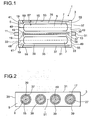
- Figure 1 shows a storage system 1 according to the invention comprising a container 3 and two storage vessels 7.
- a second gas can be filled into the storage vessels 7 and/or discharged from the storage vessels 7 through a supply pipe 48.
- the container 3 has a cuboid form and the storage vessels 7 have a cylindrical form.
- the container 3 and the storage vessels 7 are mounted in a horizontal position.
- the container 3 has a container wall 31 with two end surfaces 33 and a lateral surface 35 enclosing the storage vessels 7.
- the container 3 further has a first interior 5 and each storage vessel 7 has a second interior 9 which is filled with a sorption medium 17.
- the second interior 9 is enclosed by a storage vessel wall 15.
- the storage system 1 further comprises two housings 37 in form of hollow cylinders. Each of the housings 37 encloses one of the storage vessels 7. For each housing 37 a first opening 41 towards an inlet 11 of the container 3 and a second opening 55 towards an outlet 13 of the container 3 is provided. The inlet 11 is arranged on one end surface 33 and the outlet 13 is arranged at the opposing end surface 33 of the container wall 31.
- a stream 19 of a first gas enters the container 3 through the inlet 11 and passes the first interior 5 through gaps 39, which are provided between the storage vessel wall 15 of each storage vessel 7 and the corresponding housing 37.
- the gaps 39 have a width 57, which is constant in longitudinal direction of the storage vessel 7.
- the first gas leaves the container 3 via the outlet 13.
- baffles 59 are provided between the housings 37 and the lateral surface 35 of the container wall 31 in order to force the stream 19 of the first gas to pass between the housings 37 and the corresponding storage vessel wall 15. A dead space 53 between the housings 37 and the container wall 31 and potentially also between two housings 37, is blocked by the baffles 59.
- Figure 2 shows a radial cross-sectional view of a storage system 1 comprising four storage vessels 7 and four housings 37.
- Each storage vessel 7 has a radial cross-sectional circumference 27 of a circular form.
- the container 3 has a notional central longitudinal axis 51.
- Each storage vessel 7 is arranged coaxially with the corresponding housing 37, the housing 37 and the corresponding storage vessel 7 have an identical notional central longitudinal axis 49.
- the four storage vessels 7 with housings 37 are arranged horizontally in parallel to each other and in one plane next to each other.
- the central longitudinal axis 51 of the container 3 and the central longitudinal axis 49 of the housings 37 and storage vessels 7, are parallel to each other.
- the partial area of the radial cross-sectional area of the container 3, which is open for the first gas and which can be traversed by the stream 19 of the first gas the area, is the sum of the ringlike areas, which are assigned to the gaps 39.
- the width 57 of the gaps 39 is constant over the circumference 27 of the storage vessels.
- FIG. 3 shows a vehicle 2 according to the invention comprising a storage system 1 and a combustion engine 4.
- a second gas comprising a fuel for the combustion engine 4 is led from at least one storage vessel 7, being part of the storage system 1, through a fuel pipe 43 to the combustion engine 4.
- the second gas is combusted in the combustion engine 4 leading to a first gas comprising an exhaust gas, which is formed in the combustion engine 4.
- the combustion engine 4 supplies energy to a drive axle 41 of the vehicle 2.
- the first gas is conducted from the combustion engine 4 via a connecting pipe 45 back to the storage system 1, where the first gas passes through the first interior 5 surrounding the at least one storage vessel 7, transferring heat from the combustion carried out in the combustion engine 4 to the second gas still stored in the second interior 9 by means of the sorption medium 17.
- the first gas is conducted out of the storage system 1 via an exhaust pipe 47 to the surrounding of the vehicle 2, wherein the first gas possesses a lower temperature in the exhaust pipe 47 than in the connecting pipe 45.
- the exhaust pipe 47 may further comprise an exhaust gas
- a vehicle comprises a storage system for the storage of natural gas, which is used as fuel.
- the storage system comprises four cylindrical storage vessels with storage vessel walls made of aluminum.
- the four storage vessels are arranged in one plane parallel to each other in a horizontal position.
- Each of the four storage vessels has an inner volume of 20 L, a length in longitudinal direction of 1 m and a diameter of 28 cm.
- the four storage vessels are filled with pellets of the MOF material C300, providing a bulk density of 500 g/L and a total adsorption enthalpy, referring to natural gas, of 8 MJ.
- a maximum storage pressure in the storage vessels accounts to 60 bar.
- the four storage vessels are enclosed by a container of a cuboid form, having a length in longitudinal direction of 1 m and a height of 30 cm and a width of 120 cm.
- the container wall is made of aluminum and has a thickness of 2 mm.
- a first gas which is the exhaust gas of the combustion engine, enters the container at a first end and leaves the container at an opposing second end, wherein the distance between the first and the second end corresponds to the length in longitudinal direction of the container.
- the vehicle has a fuel consumption of 5 kg/h in average and thus an average mass flow of 10 g/s is conducted from the storage vessels to the combustion engine and back to the container of the storage system.
- the second gas which is the fuel, desorbs from the sorption medium and therefore the temperature in the storage vessels decreases.
- the mean temperature over the total volume of the storage vessels is -30°C when the storage vessels are continuously emptied until the pressure in the storage vessels is 4 bar.
- the temperature of the first gas equals the temperature of the storage vessels.
- the temperature at the storage vessel wall reaches up to 500 K, which can cause damage to the storage vessel wall, depending on its material.
- the temperature at the storage vessel wall is -15°C and the mean temperature over the total volume of the storage vessels is -10°C.
- 20 % by weight of the second gas referring to the maximum storage capacity at 60 bar, have to remain in the storage vessel in order to maintain a minimum pressure level of 4 bar within the storage vessel being required for operation of the combustion engine.
- the vehicle as described for the comparative example now comprises a storage system according to the invention, which differs from the storage system according to the comparative example in that the storage system according to the invention additionally comprises four housings in the container, each enclosing one of the four storage vessels.
- a gap is provided between each storage vessel wall and the corresponding housing with a width of 3 mm, which is constant over the length and the circumference of the storage vessels.
- the housings and corresponding storage vessels are arranged coaxially and the housings cover the complete length of the storage vessels.
- the area, which can be flowed through by the first gas in the container, is reduced compared to the comparative example.
- the stream of the first gas passes in longitudinal direction trough the container between the housings and the corresponding storage vessel walls through the gaps.
- a mean velocity of the stream of the first gas in the container is 0.1 m/s.
- the residence time of the first gas in the container is 10 seconds at 50 % of the full load of the combustion engine.
- the pressure loss in the container is less than 10 mbar at full load of the combustion engine.
- the temperature of the first gas is 500 K at the outlet of the combustion engine.
- a temperature reduction concerning the first gas from 500 K to 323 K, a heat flow of 2000 watts is available.
- the temperature of the first gas equals the temperature of the storage vessel wall not Credit reaching the last quarter, referring to the length in longitudinal direction, of the container.
- Local hotspots at the storage vessel wall in proximity to the inlet of the first gas show a reduced temperature of only 350 K, compared to the comparative example.
- the temperature at the storage vessel wall is 20°C.
- the mean temperature in the storage vessels, after desorption of the second gas and when the minimum storage pressure of 4 bar in the storage vessels is reached, is now 50°C.
Landscapes
- Engineering & Computer Science (AREA)
- Chemical & Material Sciences (AREA)
- Chemical Kinetics & Catalysis (AREA)
- General Chemical & Material Sciences (AREA)
- Oil, Petroleum & Natural Gas (AREA)
- Mechanical Engineering (AREA)
- General Engineering & Computer Science (AREA)
- Filling Or Discharging Of Gas Storage Vessels (AREA)
Priority Applications (1)
| Application Number | Priority Date | Filing Date | Title |
|---|---|---|---|
| EP15180947.2A EP3130835A1 (de) | 2015-08-13 | 2015-08-13 | Fahrzeug mit einem aufbewahrungssystem und einem verbrennungsmotor, das aufbewahrungssystem mit einem container und mindestens einem aufbewahrungsbehälter mit einem gehäuse |
Applications Claiming Priority (1)
| Application Number | Priority Date | Filing Date | Title |
|---|---|---|---|
| EP15180947.2A EP3130835A1 (de) | 2015-08-13 | 2015-08-13 | Fahrzeug mit einem aufbewahrungssystem und einem verbrennungsmotor, das aufbewahrungssystem mit einem container und mindestens einem aufbewahrungsbehälter mit einem gehäuse |
Publications (1)
| Publication Number | Publication Date |
|---|---|
| EP3130835A1 true EP3130835A1 (de) | 2017-02-15 |
Family
ID=53835977
Family Applications (1)
| Application Number | Title | Priority Date | Filing Date |
|---|---|---|---|
| EP15180947.2A Ceased EP3130835A1 (de) | 2015-08-13 | 2015-08-13 | Fahrzeug mit einem aufbewahrungssystem und einem verbrennungsmotor, das aufbewahrungssystem mit einem container und mindestens einem aufbewahrungsbehälter mit einem gehäuse |
Country Status (1)
| Country | Link |
|---|---|
| EP (1) | EP3130835A1 (de) |
Cited By (4)
| Publication number | Priority date | Publication date | Assignee | Title |
|---|---|---|---|---|
| CN111591396A (zh) * | 2019-06-25 | 2020-08-28 | 南京蒽天捷能源科技有限公司 | 可移动串联式浮动液货过驳海工平台及过驳方法 |
| JP2022022956A (ja) * | 2020-06-30 | 2022-02-07 | 日産自動車株式会社 | 天然ガスの吸着貯蔵システム |
| CN115654363A (zh) * | 2022-12-30 | 2023-01-31 | 长春吉电氢能有限公司 | 一种制氢站智慧运行监控方法和系统 |
| US20230055646A1 (en) * | 2020-01-29 | 2023-02-23 | Robert Bosch Gmbh | Pressurized gas tank receiving assembly for a motor vehicle |
Citations (30)
| Publication number | Priority date | Publication date | Assignee | Title |
|---|---|---|---|---|
| US4016836A (en) * | 1975-09-08 | 1977-04-12 | Billings Energy Research Corporation | Hydride fuel system |
| US4165569A (en) * | 1975-04-21 | 1979-08-28 | Billings Energy Corporation | Hydride storage and heat exchanger system and method |
| EP0200260A2 (de) | 1985-04-23 | 1986-12-10 | ENICHEM SYNTHESIS S.p.A. | Katalysator auf Basis von Silicium und Titanium, der eine hohe mechanische Festigkeit hat |
| EP0102544B1 (de) | 1982-08-25 | 1988-06-01 | BASF Aktiengesellschaft | Verfahren zur Herstellung von harten, bruchfesten Katalysatoren aus Zeolith-Pulver |
| EP0389041A1 (de) | 1989-03-23 | 1990-09-26 | Shell Internationale Researchmaatschappij B.V. | Titanoxyd-Extrudate |
| JPH0337156A (ja) | 1989-07-03 | 1991-02-18 | Sumitomo Metal Mining Co Ltd | ゼオライト成型焼成体及びその製造方法 |
| EP0592050A1 (de) | 1992-10-08 | 1994-04-13 | Shell Internationale Researchmaatschappij B.V. | Extrusionsverfahren für kristalline Aluminosilikate |
| WO1994013584A1 (en) | 1992-12-16 | 1994-06-23 | Chevron Research And Technology Company, A Division Of Chevron U.S.A. Inc. | Preparation of aluminosilicate zeolites |
| WO1994029408A1 (en) | 1993-06-03 | 1994-12-22 | Mobil Oil Corporation | Process for preparing an alumina bound zeolite catalyst |
| WO1995019222A1 (en) | 1994-01-12 | 1995-07-20 | E.I. Du Pont De Nemours And Company | Sol-gel derived porous microcomposite of perfluorinated ion-exchange polymer and metal oxide |
| EP0700253A1 (de) | 1993-04-27 | 1996-03-13 | Gist-Brocades B.V. | Käsebereitung mit rekombinantem aspartat-protease |
| US5648508A (en) | 1995-11-22 | 1997-07-15 | Nalco Chemical Company | Crystalline metal-organic microporous materials |
| DE10111230A1 (de) | 2001-03-08 | 2002-09-19 | Basf Ag | Metallorganische Gerüstmaterialien und Verfahren zu deren Herstellung |
| WO2003064030A1 (de) | 2002-02-01 | 2003-08-07 | Basf Aktiengesellschaft | Verfahren zum speichern, zur aufnahme und abgabe von gasen unter verwendung neuartiger gerüstmaterialien |
| WO2003102000A1 (en) | 2002-05-30 | 2003-12-11 | Basf Aktiengesellschaft | Shaped bodies containing metal-organic frameworks |
| WO2005003622A1 (en) | 2003-06-30 | 2005-01-13 | Basf Aktiengesellschaft | Non cylindrical gas storage tank using adsordent comprising bidentate organic compund |
| WO2005049892A1 (de) | 2003-11-24 | 2005-06-02 | Basf Aktiengesellschaft | Verfahren zur elektrochemischen herstellung eines kristallinen porösen metallorganischen gerüstmaterials |
| US20050287407A1 (en) * | 2004-06-28 | 2005-12-29 | Bushko Wit C | System and method for storing and discharging hydrogen |
| WO2006089908A1 (en) | 2005-02-23 | 2006-08-31 | Basf Aktiengesellschaft | Metal-organic framework materials for gaseous hydrocarbon storage |
| DE102005012087A1 (de) | 2005-03-16 | 2006-09-21 | Basf Ag | Flüssigkeitsabsorption durch metallorganische Gerüstmaterialien |
| WO2007023134A1 (de) | 2005-08-22 | 2007-03-01 | Basf Aktiengesellschaft | Verfahren zur herstellung von metallorganischen gerüstmaterialien hauptgruppen metallionen enthaltend |
| DE102005053430A1 (de) | 2005-11-09 | 2007-05-16 | Basf Ag | Dotierte metallorganische Gerüstmaterialien |
| WO2007054581A2 (de) | 2005-11-14 | 2007-05-18 | Basf Se | Poröses metallorganisches gerüstmaterial enthaltend ein weiteres polymer |
| US20080168776A1 (en) | 2007-01-11 | 2008-07-17 | Gm Global Technology Operations, Inc. | Hydrogen Storage Tank System Based on Gas Adsorption on High-Surface Materials Comprising an Integrated Heat Exchanger |
| US20080290645A1 (en) | 2007-05-21 | 2008-11-27 | Kiyoshi Handa | Shaped Absorbent Media Installed in a High Pressure Tank |
| US7637292B2 (en) | 2005-05-09 | 2009-12-29 | Honda Motor Co., Ltd. | Pressure powered cooling system for enhancing the refill speed and capacity of on board high pressure vehicle gas storage tanks |
| EP2230288A2 (de) | 2009-03-20 | 2010-09-22 | Basf Se | Metallorganische Gerüstmaterialien in Kälte/Wärmemaschinen |
| WO2013130401A1 (en) | 2012-02-29 | 2013-09-06 | Luon Energy Llc | Natural gas adsorption devices |
| WO2014057416A1 (en) | 2012-10-09 | 2014-04-17 | Basf Se | Method of charging a sorption store with a gas |
| US20140290611A1 (en) | 2013-03-28 | 2014-10-02 | GM Global Technology Operations LLC | Natural gas storage system and method of improving efficiency thereof |
-
2015
- 2015-08-13 EP EP15180947.2A patent/EP3130835A1/de not_active Ceased
Patent Citations (32)
| Publication number | Priority date | Publication date | Assignee | Title |
|---|---|---|---|---|
| US4165569A (en) * | 1975-04-21 | 1979-08-28 | Billings Energy Corporation | Hydride storage and heat exchanger system and method |
| US4016836A (en) * | 1975-09-08 | 1977-04-12 | Billings Energy Research Corporation | Hydride fuel system |
| EP0102544B1 (de) | 1982-08-25 | 1988-06-01 | BASF Aktiengesellschaft | Verfahren zur Herstellung von harten, bruchfesten Katalysatoren aus Zeolith-Pulver |
| EP0200260A2 (de) | 1985-04-23 | 1986-12-10 | ENICHEM SYNTHESIS S.p.A. | Katalysator auf Basis von Silicium und Titanium, der eine hohe mechanische Festigkeit hat |
| EP0389041A1 (de) | 1989-03-23 | 1990-09-26 | Shell Internationale Researchmaatschappij B.V. | Titanoxyd-Extrudate |
| JPH0337156A (ja) | 1989-07-03 | 1991-02-18 | Sumitomo Metal Mining Co Ltd | ゼオライト成型焼成体及びその製造方法 |
| EP0592050A1 (de) | 1992-10-08 | 1994-04-13 | Shell Internationale Researchmaatschappij B.V. | Extrusionsverfahren für kristalline Aluminosilikate |
| WO1994013584A1 (en) | 1992-12-16 | 1994-06-23 | Chevron Research And Technology Company, A Division Of Chevron U.S.A. Inc. | Preparation of aluminosilicate zeolites |
| EP0700253A1 (de) | 1993-04-27 | 1996-03-13 | Gist-Brocades B.V. | Käsebereitung mit rekombinantem aspartat-protease |
| WO1994029408A1 (en) | 1993-06-03 | 1994-12-22 | Mobil Oil Corporation | Process for preparing an alumina bound zeolite catalyst |
| WO1995019222A1 (en) | 1994-01-12 | 1995-07-20 | E.I. Du Pont De Nemours And Company | Sol-gel derived porous microcomposite of perfluorinated ion-exchange polymer and metal oxide |
| US5648508A (en) | 1995-11-22 | 1997-07-15 | Nalco Chemical Company | Crystalline metal-organic microporous materials |
| DE10111230A1 (de) | 2001-03-08 | 2002-09-19 | Basf Ag | Metallorganische Gerüstmaterialien und Verfahren zu deren Herstellung |
| WO2003064030A1 (de) | 2002-02-01 | 2003-08-07 | Basf Aktiengesellschaft | Verfahren zum speichern, zur aufnahme und abgabe von gasen unter verwendung neuartiger gerüstmaterialien |
| WO2003102000A1 (en) | 2002-05-30 | 2003-12-11 | Basf Aktiengesellschaft | Shaped bodies containing metal-organic frameworks |
| WO2005003622A1 (en) | 2003-06-30 | 2005-01-13 | Basf Aktiengesellschaft | Non cylindrical gas storage tank using adsordent comprising bidentate organic compund |
| WO2005049892A1 (de) | 2003-11-24 | 2005-06-02 | Basf Aktiengesellschaft | Verfahren zur elektrochemischen herstellung eines kristallinen porösen metallorganischen gerüstmaterials |
| DE10355087A1 (de) | 2003-11-24 | 2005-06-09 | Basf Ag | Verfahren zur elektrochemischen Herstellung eines kristallinen porösen metallorganischen Gerüstmaterials |
| WO2005049484A1 (de) | 2003-11-24 | 2005-06-02 | Basf Aktiengesellschaft | Verfahren zur kontrollierten speicherung und abgabe von gasen unter einsatz eines elektrochemisch hergestellten kristallinen porösen metallorganischen gerüstmaterials |
| US20050287407A1 (en) * | 2004-06-28 | 2005-12-29 | Bushko Wit C | System and method for storing and discharging hydrogen |
| WO2006089908A1 (en) | 2005-02-23 | 2006-08-31 | Basf Aktiengesellschaft | Metal-organic framework materials for gaseous hydrocarbon storage |
| DE102005012087A1 (de) | 2005-03-16 | 2006-09-21 | Basf Ag | Flüssigkeitsabsorption durch metallorganische Gerüstmaterialien |
| US7637292B2 (en) | 2005-05-09 | 2009-12-29 | Honda Motor Co., Ltd. | Pressure powered cooling system for enhancing the refill speed and capacity of on board high pressure vehicle gas storage tanks |
| WO2007023134A1 (de) | 2005-08-22 | 2007-03-01 | Basf Aktiengesellschaft | Verfahren zur herstellung von metallorganischen gerüstmaterialien hauptgruppen metallionen enthaltend |
| DE102005053430A1 (de) | 2005-11-09 | 2007-05-16 | Basf Ag | Dotierte metallorganische Gerüstmaterialien |
| WO2007054581A2 (de) | 2005-11-14 | 2007-05-18 | Basf Se | Poröses metallorganisches gerüstmaterial enthaltend ein weiteres polymer |
| US20080168776A1 (en) | 2007-01-11 | 2008-07-17 | Gm Global Technology Operations, Inc. | Hydrogen Storage Tank System Based on Gas Adsorption on High-Surface Materials Comprising an Integrated Heat Exchanger |
| US20080290645A1 (en) | 2007-05-21 | 2008-11-27 | Kiyoshi Handa | Shaped Absorbent Media Installed in a High Pressure Tank |
| EP2230288A2 (de) | 2009-03-20 | 2010-09-22 | Basf Se | Metallorganische Gerüstmaterialien in Kälte/Wärmemaschinen |
| WO2013130401A1 (en) | 2012-02-29 | 2013-09-06 | Luon Energy Llc | Natural gas adsorption devices |
| WO2014057416A1 (en) | 2012-10-09 | 2014-04-17 | Basf Se | Method of charging a sorption store with a gas |
| US20140290611A1 (en) | 2013-03-28 | 2014-10-02 | GM Global Technology Operations LLC | Natural gas storage system and method of improving efficiency thereof |
Non-Patent Citations (6)
| Title |
|---|
| "Ullmann's Enzykiopadie der Technischen Chemie", vol. 2, 1972, pages: 313 |
| B. CHEN ET AL., SCIENCE, vol. 291, 2001, pages 1021 - 1023 |
| DAVID FARRUSSENG: "Metal-Organic Frameworks", 2011, WILEY-VCH VERLAG |
| H. LI ET AL., NATURE, vol. 402, no. 1, 1999, pages 276 |
| M. EDDAOUDI ET AL., TOPICS IN CATALYSIS, vol. 9, 1999, pages 105 - 111 |
| M. O'KEEFFE ET AL., J. SOL. STATE CHEM., vol. 152, 2000, pages 3 - 20 |
Cited By (6)
| Publication number | Priority date | Publication date | Assignee | Title |
|---|---|---|---|---|
| CN111591396A (zh) * | 2019-06-25 | 2020-08-28 | 南京蒽天捷能源科技有限公司 | 可移动串联式浮动液货过驳海工平台及过驳方法 |
| US20230055646A1 (en) * | 2020-01-29 | 2023-02-23 | Robert Bosch Gmbh | Pressurized gas tank receiving assembly for a motor vehicle |
| US12370884B2 (en) * | 2020-01-29 | 2025-07-29 | Robert Bosch Gmbh | Pressurized gas tank receiving assembly for a motor vehicle |
| JP2022022956A (ja) * | 2020-06-30 | 2022-02-07 | 日産自動車株式会社 | 天然ガスの吸着貯蔵システム |
| CN115654363A (zh) * | 2022-12-30 | 2023-01-31 | 长春吉电氢能有限公司 | 一种制氢站智慧运行监控方法和系统 |
| CN115654363B (zh) * | 2022-12-30 | 2023-03-07 | 长春吉电氢能有限公司 | 一种制氢站智慧运行监控方法和系统 |
Similar Documents
| Publication | Publication Date | Title |
|---|---|---|
| WO2016135133A1 (en) | A vehicle comprising a storage system and a combustion engine, the storage system comprising a container and at least one storage vessel | |
| KR101426969B1 (ko) | 수소 저장 및 냉각 방법 | |
| EP3093549A1 (de) | Fahrzeug mit verbrennungsmotor, mindestens einem aufbewahrungsbehälter und einer kühlkammer und/oder einer klimaanlageneinheit | |
| US9175591B2 (en) | Process and system employing phase-changing absorbents and magnetically responsive sorbent particles for on-board recovery of carbon dioxide from mobile sources | |
| US20160201855A1 (en) | Sorption store with improved heat transfer | |
| EP3093550A1 (de) | Lagerbehälter mit mindestens einem formkörper eines porösen feststoffs | |
| CN106922168B (zh) | 包括多孔固体的一体式成形体的储存容器 | |
| EP1651903A1 (de) | Nicht-zylindrischer gasbehälter unter verwendung eines zweizähnige organische verbindungen enthaltenden adsorbents | |
| US20160186932A1 (en) | Process for filling a sorption store with gas | |
| KR20070005697A (ko) | 흡착성 가스 연료용 저장 시스템과 그 제작 방법 | |
| WO2016075100A1 (en) | Storage vessel comprising layers of a shaped body of a porous solid separated by a seal | |
| SE458466B (sv) | Anordning samt foerfarande foer drivning av ett med naturgas arbetande drivaggregat foer ett fordon | |
| CN105209815A (zh) | 气体储存模块,装置,系统以及利用吸附材料的方法 | |
| CN102348501A (zh) | 具有吸气材料的真空绝缘单元 | |
| WO2016075129A1 (en) | Storage vessel comprising at least one shaped body of a porous solid with spacers | |
| WO2023225343A9 (en) | Liquefied gas system with boil-off capture | |
| WO2015022633A1 (en) | Sorption store for gas with multiple adsorbent media | |
| EP3130834A1 (de) | Fahrzeug mit einem aufbewahrungssystem und einem verbrennungsmotor, das aufbewahrungssystem mit einem container und mindestens zwei aufbewahrungsbehältern | |
| US20180023518A1 (en) | Fuel gas fueling system and method | |
| RU2648387C1 (ru) | Адсорбционный газовый терминал |
Legal Events
| Date | Code | Title | Description |
|---|---|---|---|
| PUAI | Public reference made under article 153(3) epc to a published international application that has entered the european phase |
Free format text: ORIGINAL CODE: 0009012 |
|
| AK | Designated contracting states |
Kind code of ref document: A1 Designated state(s): AL AT BE BG CH CY CZ DE DK EE ES FI FR GB GR HR HU IE IS IT LI LT LU LV MC MK MT NL NO PL PT RO RS SE SI SK SM TR |
|
| AX | Request for extension of the european patent |
Extension state: BA ME |
|
| STAA | Information on the status of an ep patent application or granted ep patent |
Free format text: STATUS: THE APPLICATION HAS BEEN REFUSED |
|
| 18R | Application refused |
Effective date: 20170304 |