EP3130848B1 - Dispositif à combustion séquentielle avec gaz de refroidissement pour la dilution - Google Patents
Dispositif à combustion séquentielle avec gaz de refroidissement pour la dilution Download PDFInfo
- Publication number
- EP3130848B1 EP3130848B1 EP15180787.2A EP15180787A EP3130848B1 EP 3130848 B1 EP3130848 B1 EP 3130848B1 EP 15180787 A EP15180787 A EP 15180787A EP 3130848 B1 EP3130848 B1 EP 3130848B1
- Authority
- EP
- European Patent Office
- Prior art keywords
- gas
- cooling
- combustor
- admixer
- dilution
- Prior art date
- Legal status (The legal status is an assumption and is not a legal conclusion. Google has not performed a legal analysis and makes no representation as to the accuracy of the status listed.)
- Active
Links
Images

Classifications
-
- F—MECHANICAL ENGINEERING; LIGHTING; HEATING; WEAPONS; BLASTING
- F23—COMBUSTION APPARATUS; COMBUSTION PROCESSES
- F23C—METHODS OR APPARATUS FOR COMBUSTION USING FLUID FUEL OR SOLID FUEL SUSPENDED IN A CARRIER GAS OR AIR
- F23C6/00—Combustion apparatus characterised by the combination of two or more combustion chambers or combustion zones, e.g. for staged combustion
- F23C6/04—Combustion apparatus characterised by the combination of two or more combustion chambers or combustion zones, e.g. for staged combustion in series connection
- F23C6/045—Combustion apparatus characterised by the combination of two or more combustion chambers or combustion zones, e.g. for staged combustion in series connection with staged combustion in a single enclosure
- F23C6/047—Combustion apparatus characterised by the combination of two or more combustion chambers or combustion zones, e.g. for staged combustion in series connection with staged combustion in a single enclosure with fuel supply in stages
-
- F—MECHANICAL ENGINEERING; LIGHTING; HEATING; WEAPONS; BLASTING
- F23—COMBUSTION APPARATUS; COMBUSTION PROCESSES
- F23R—GENERATING COMBUSTION PRODUCTS OF HIGH PRESSURE OR HIGH VELOCITY, e.g. GAS-TURBINE COMBUSTION CHAMBERS
- F23R3/00—Continuous combustion chambers using liquid or gaseous fuel
- F23R3/42—Continuous combustion chambers using liquid or gaseous fuel characterised by the arrangement or form of the flame tubes or combustion chambers
-
- F—MECHANICAL ENGINEERING; LIGHTING; HEATING; WEAPONS; BLASTING
- F02—COMBUSTION ENGINES; HOT-GAS OR COMBUSTION-PRODUCT ENGINE PLANTS
- F02C—GAS-TURBINE PLANTS; AIR INTAKES FOR JET-PROPULSION PLANTS; CONTROLLING FUEL SUPPLY IN AIR-BREATHING JET-PROPULSION PLANTS
- F02C7/00—Features, components parts, details or accessories, not provided for in, or of interest apart form groups F02C1/00 - F02C6/00; Air intakes for jet-propulsion plants
- F02C7/12—Cooling of plants
- F02C7/14—Cooling of plants of fluids in the plant, e.g. lubricant or fuel
- F02C7/141—Cooling of plants of fluids in the plant, e.g. lubricant or fuel of working fluid
-
- F—MECHANICAL ENGINEERING; LIGHTING; HEATING; WEAPONS; BLASTING
- F01—MACHINES OR ENGINES IN GENERAL; ENGINE PLANTS IN GENERAL; STEAM ENGINES
- F01D—NON-POSITIVE DISPLACEMENT MACHINES OR ENGINES, e.g. STEAM TURBINES
- F01D25/00—Component parts, details, or accessories, not provided for in, or of interest apart from, other groups
- F01D25/08—Cooling; Heating; Heat-insulation
- F01D25/12—Cooling
-
- F—MECHANICAL ENGINEERING; LIGHTING; HEATING; WEAPONS; BLASTING
- F01—MACHINES OR ENGINES IN GENERAL; ENGINE PLANTS IN GENERAL; STEAM ENGINES
- F01D—NON-POSITIVE DISPLACEMENT MACHINES OR ENGINES, e.g. STEAM TURBINES
- F01D5/00—Blades; Blade-carrying members; Heating, heat-insulating, cooling or antivibration means on the blades or the members
- F01D5/12—Blades
- F01D5/14—Form or construction
- F01D5/18—Hollow blades, i.e. blades with cooling or heating channels or cavities; Heating, heat-insulating or cooling means on blades
- F01D5/187—Convection cooling
-
- F—MECHANICAL ENGINEERING; LIGHTING; HEATING; WEAPONS; BLASTING
- F01—MACHINES OR ENGINES IN GENERAL; ENGINE PLANTS IN GENERAL; STEAM ENGINES
- F01D—NON-POSITIVE DISPLACEMENT MACHINES OR ENGINES, e.g. STEAM TURBINES
- F01D9/00—Stators
- F01D9/02—Nozzles; Nozzle boxes; Stator blades; Guide conduits, e.g. individual nozzles
- F01D9/04—Nozzles; Nozzle boxes; Stator blades; Guide conduits, e.g. individual nozzles forming ring or sector
- F01D9/041—Nozzles; Nozzle boxes; Stator blades; Guide conduits, e.g. individual nozzles forming ring or sector using blades
-
- F—MECHANICAL ENGINEERING; LIGHTING; HEATING; WEAPONS; BLASTING
- F02—COMBUSTION ENGINES; HOT-GAS OR COMBUSTION-PRODUCT ENGINE PLANTS
- F02C—GAS-TURBINE PLANTS; AIR INTAKES FOR JET-PROPULSION PLANTS; CONTROLLING FUEL SUPPLY IN AIR-BREATHING JET-PROPULSION PLANTS
- F02C7/00—Features, components parts, details or accessories, not provided for in, or of interest apart form groups F02C1/00 - F02C6/00; Air intakes for jet-propulsion plants
- F02C7/12—Cooling of plants
- F02C7/16—Cooling of plants characterised by cooling medium
- F02C7/18—Cooling of plants characterised by cooling medium the medium being gaseous, e.g. air
-
- F—MECHANICAL ENGINEERING; LIGHTING; HEATING; WEAPONS; BLASTING
- F02—COMBUSTION ENGINES; HOT-GAS OR COMBUSTION-PRODUCT ENGINE PLANTS
- F02C—GAS-TURBINE PLANTS; AIR INTAKES FOR JET-PROPULSION PLANTS; CONTROLLING FUEL SUPPLY IN AIR-BREATHING JET-PROPULSION PLANTS
- F02C7/00—Features, components parts, details or accessories, not provided for in, or of interest apart form groups F02C1/00 - F02C6/00; Air intakes for jet-propulsion plants
- F02C7/22—Fuel supply systems
-
- F—MECHANICAL ENGINEERING; LIGHTING; HEATING; WEAPONS; BLASTING
- F23—COMBUSTION APPARATUS; COMBUSTION PROCESSES
- F23R—GENERATING COMBUSTION PRODUCTS OF HIGH PRESSURE OR HIGH VELOCITY, e.g. GAS-TURBINE COMBUSTION CHAMBERS
- F23R3/00—Continuous combustion chambers using liquid or gaseous fuel
- F23R3/02—Continuous combustion chambers using liquid or gaseous fuel characterised by the air-flow or gas-flow configuration
-
- F—MECHANICAL ENGINEERING; LIGHTING; HEATING; WEAPONS; BLASTING
- F23—COMBUSTION APPARATUS; COMBUSTION PROCESSES
- F23R—GENERATING COMBUSTION PRODUCTS OF HIGH PRESSURE OR HIGH VELOCITY, e.g. GAS-TURBINE COMBUSTION CHAMBERS
- F23R3/00—Continuous combustion chambers using liquid or gaseous fuel
- F23R3/28—Continuous combustion chambers using liquid or gaseous fuel characterised by the fuel supply
- F23R3/286—Continuous combustion chambers using liquid or gaseous fuel characterised by the fuel supply having fuel-air premixing devices
-
- F—MECHANICAL ENGINEERING; LIGHTING; HEATING; WEAPONS; BLASTING
- F23—COMBUSTION APPARATUS; COMBUSTION PROCESSES
- F23R—GENERATING COMBUSTION PRODUCTS OF HIGH PRESSURE OR HIGH VELOCITY, e.g. GAS-TURBINE COMBUSTION CHAMBERS
- F23R3/00—Continuous combustion chambers using liquid or gaseous fuel
- F23R3/28—Continuous combustion chambers using liquid or gaseous fuel characterised by the fuel supply
- F23R3/34—Feeding into different combustion zones
-
- F—MECHANICAL ENGINEERING; LIGHTING; HEATING; WEAPONS; BLASTING
- F23—COMBUSTION APPARATUS; COMBUSTION PROCESSES
- F23R—GENERATING COMBUSTION PRODUCTS OF HIGH PRESSURE OR HIGH VELOCITY, e.g. GAS-TURBINE COMBUSTION CHAMBERS
- F23R3/00—Continuous combustion chambers using liquid or gaseous fuel
- F23R3/28—Continuous combustion chambers using liquid or gaseous fuel characterised by the fuel supply
- F23R3/34—Feeding into different combustion zones
- F23R3/346—Feeding into different combustion zones for staged combustion
-
- F—MECHANICAL ENGINEERING; LIGHTING; HEATING; WEAPONS; BLASTING
- F23—COMBUSTION APPARATUS; COMBUSTION PROCESSES
- F23R—GENERATING COMBUSTION PRODUCTS OF HIGH PRESSURE OR HIGH VELOCITY, e.g. GAS-TURBINE COMBUSTION CHAMBERS
- F23R3/00—Continuous combustion chambers using liquid or gaseous fuel
- F23R3/28—Continuous combustion chambers using liquid or gaseous fuel characterised by the fuel supply
- F23R3/36—Supply of different fuels
-
- F—MECHANICAL ENGINEERING; LIGHTING; HEATING; WEAPONS; BLASTING
- F05—INDEXING SCHEMES RELATING TO ENGINES OR PUMPS IN VARIOUS SUBCLASSES OF CLASSES F01-F04
- F05D—INDEXING SCHEME FOR ASPECTS RELATING TO NON-POSITIVE-DISPLACEMENT MACHINES OR ENGINES, GAS-TURBINES OR JET-PROPULSION PLANTS
- F05D2220/00—Application
- F05D2220/30—Application in turbines
- F05D2220/32—Application in turbines in gas turbines
-
- F—MECHANICAL ENGINEERING; LIGHTING; HEATING; WEAPONS; BLASTING
- F05—INDEXING SCHEMES RELATING TO ENGINES OR PUMPS IN VARIOUS SUBCLASSES OF CLASSES F01-F04
- F05D—INDEXING SCHEME FOR ASPECTS RELATING TO NON-POSITIVE-DISPLACEMENT MACHINES OR ENGINES, GAS-TURBINES OR JET-PROPULSION PLANTS
- F05D2240/00—Components
- F05D2240/35—Combustors or associated equipment
-
- F—MECHANICAL ENGINEERING; LIGHTING; HEATING; WEAPONS; BLASTING
- F05—INDEXING SCHEMES RELATING TO ENGINES OR PUMPS IN VARIOUS SUBCLASSES OF CLASSES F01-F04
- F05D—INDEXING SCHEME FOR ASPECTS RELATING TO NON-POSITIVE-DISPLACEMENT MACHINES OR ENGINES, GAS-TURBINES OR JET-PROPULSION PLANTS
- F05D2260/00—Function
- F05D2260/20—Heat transfer, e.g. cooling
- F05D2260/201—Heat transfer, e.g. cooling by impingement of a fluid
-
- F—MECHANICAL ENGINEERING; LIGHTING; HEATING; WEAPONS; BLASTING
- F23—COMBUSTION APPARATUS; COMBUSTION PROCESSES
- F23R—GENERATING COMBUSTION PRODUCTS OF HIGH PRESSURE OR HIGH VELOCITY, e.g. GAS-TURBINE COMBUSTION CHAMBERS
- F23R2900/00—Special features of, or arrangements for continuous combustion chambers; Combustion processes therefor
- F23R2900/03041—Effusion cooled combustion chamber walls or domes
-
- F—MECHANICAL ENGINEERING; LIGHTING; HEATING; WEAPONS; BLASTING
- F23—COMBUSTION APPARATUS; COMBUSTION PROCESSES
- F23R—GENERATING COMBUSTION PRODUCTS OF HIGH PRESSURE OR HIGH VELOCITY, e.g. GAS-TURBINE COMBUSTION CHAMBERS
- F23R2900/00—Special features of, or arrangements for continuous combustion chambers; Combustion processes therefor
- F23R2900/03341—Sequential combustion chambers or burners
-
- Y—GENERAL TAGGING OF NEW TECHNOLOGICAL DEVELOPMENTS; GENERAL TAGGING OF CROSS-SECTIONAL TECHNOLOGIES SPANNING OVER SEVERAL SECTIONS OF THE IPC; TECHNICAL SUBJECTS COVERED BY FORMER USPC CROSS-REFERENCE ART COLLECTIONS [XRACs] AND DIGESTS
- Y02—TECHNOLOGIES OR APPLICATIONS FOR MITIGATION OR ADAPTATION AGAINST CLIMATE CHANGE
- Y02E—REDUCTION OF GREENHOUSE GAS [GHG] EMISSIONS, RELATED TO ENERGY GENERATION, TRANSMISSION OR DISTRIBUTION
- Y02E20/00—Combustion technologies with mitigation potential
- Y02E20/16—Combined cycle power plant [CCPP], or combined cycle gas turbine [CCGT]
Definitions
- the invention refers to a sequential combustor arrangement for a gas turbine with admixing returned turbine cooling gas as dilution gas into the sequential combustor arrangement.
- the invention additionally refers to a method for operating a gas turbine with admixing returned turbine cooling gas as dilution gas into a sequential combustor arrangement.
- emission limit values and overall emission permits are becoming more stringent, so that it is required to operate at lower emission values, keep low emissions also at part load operation and during transients, as these also count for cumulative emission limits.
- State-of-the-art combustion systems are designed to cope with a certain variability in operating conditions, e.g. by adjusting the compressor inlet mass flow or controlling the fuel split among different burners, fuel stages or combustors. However, this is not sufficient to meet the new requirements.
- US 20120260665 A1 discloses a reheat combustor for a gas turbine comprising a first combuster having a first burner and a fist combustion chamber, a second comuster having a second burner and a second combustion chamber and a dilution gas admixer for mixing a second fuel injected by fuel injectors of the second combuster, a dilution gas and the first combustor combustion products, the latter ones having been expanded through a high-pressure turbine.
- the admixer and the second combustion chamber comprise cooling conduits through which the dilution gas circulates and which convectively cool the respective walls.
- the inlet guide vanes also comprise cooling conduits in series with the cooling conduits of the second combustion chamber.
- the object of the present disclosure is to propose a gas turbine with a sequential combustor arrangement comprising means for admixing dilution gas and the second fuel between the first combustion chamber and the second combustion chamber.
- a "dilution burner” has to provide the proper inlet flow conditions for the second combustor for a wide operating range of the gas turbine without impairing power and efficiency of the gas turbine.
- predefined inlet conditions have to be assured for all operating conditions in which the second combustor is operating.
- the hot gases are cooled to predetermined hot gas temperatures.
- velocity distribution, oxygen and fuel content can be conditioned (e.g. controlled to a prescribed profile) for the second combustion chamber with proper admixing of dilution gas.
- the second combustor typically comprises a second burner and a second combustion chamber.
- the second burner can be integrated or combined with the dilution gas admixer.
- Deviations from prescribed inlet temperatures may result in high emissions (e.g. NOx, CO, and unburned hydrocarbons) and/or flashback in the dilution burner. Flashback and NOx are induced by the reduced self-ignition time for the injected fuel due to a high inlet gas temperature or high oxygen concentration, which causes earlier ignition (leading to flashback) or reduced time for fuel air mixing resulting in local hot spots during combustion and consequently increased NOx emission. Low temperature regions can cause CO emissions, due to the increased self-ignition time. This can reduce the time for CO to CO2 burnout, and a reduced local flame temperature, which can further slowdown the CO to CO2 burnout. Finally local hot spots may lead to overheating in certain regions downstream of the mixer.
- high emissions e.g. NOx, CO, and unburned hydrocarbons
- flashback and NOx are induced by the reduced self-ignition time for the injected fuel due to a high inlet gas temperature or high oxygen concentration, which causes earlier ignition (leading to flashback) or reduced time
- Dilution gas can for example be compressed air or a mixture of air and flue gases of a gas turbine. Also compressed flue gases can be used as dilution gas.
- the sequential combustor arrangement comprising a first combustor with a first burner for admitting a first fuel into a combustor inlet gas during operation, and a first combustion chamber for burning the first fuel with the combustor inlet gas.
- the combustor inlet gas is compressed air.
- it can be another gas or gas mixture such as for example a mixture of air and a flue gas.
- the sequential combustor arrangement further comprises a dilution gas admixer for admixing a dilution gas to the first combustor combustion products leaving the first combustion chamber, and a second burner for admixing a second fuel and a second combustion chamber.
- the second fuel can be burned with the mixture of first combustion products and dilution air in the second combustion chamber.
- the first combustor, the dilution gas admixer, the second burner and second combustion chamber are arranged sequentially in a fluid flow connection.
- the second burner and the second combustion chamber are arranged downstream from the dilution gas admixer.
- a vane and/or blade of the turbine has a closed loop cooling is proposed. It can be connected to a compressor plenum for feeding compressed cooling fluid into the vane and/or blade.
- the outlet of the closed loop cooling is connected to the dilution gas admixer for admixing the heated cooling gas leaving the vane and/or blade into the first combustor combustion products during operation of the gas turbine.
- the cooling gas is heated for example to a temperature above the compressor exit temperature thus reducing the temperature difference between hot gases and dilution gas thereby facilitating the generation of a homogeneous temperature profile.
- reduced NOx emission values can be achieved for the same hot gas temperature due to better temperature profiles.
- the gas turbine efficiency can be increase because of the closed loop cooling.
- the mixed turbine inlet temperature can be increased for the same hot gas temperature by application of a closed loop cooling thereby increasing power end efficiency of the gas turbine and a combined cycle power plant with such a gas turbine.
- a closed loop cooling system is a way of cooling in which cooling gas is fed into the vane or blade at one end of the closed loop cooling, used for internal cooling of the blade, and flows to an outlet of the closed loop cooling.
- cooling gas is fed into a vane or blade and then discharged from the blade or vane into the hot gas flowing around the vane or blade the cooling gas leaving the closed loop cooling at the outlet can be further used e.g. for cooling or admixing.
- the first combustor has a pressure drop which can for example be in the order of 3% to 7%, or in another example in the range of 4% to 5% of the total pressure in the compressor plenum.
- This pressure drop can be used to feed gas from the compressor plenum through the closed loop cooling, supply it to the dilution gas admixer and to inject the heated cooling gas into the to the first combustor combustion products leaving the first combustion chamber.
- the heated cooling gas therefor can still be used in the second combustor upstream of the flame of the second combustor.
- the proposed arrangement enables the use of a closed loop cooling which is fed from the compressor plenum for additional cooling purposes and dilution gas admixing without any recompression. Recompression is required in conventional gas turbines with only one combustion chamber to re-inject or admix cooling gas into the combustor arrangement upstream of a flame.
- the invention presents a way to use the first combustor's pressure drop for cooling purposes. Thereby cooling air for the turbine can be saved and at the same time heat from the turbine cooling can be recuperated to the second combustor.
- the gas turbine comprises a cooling gas feed which connects the compressor plenum with the closed loop cooling for feeding compressed gas leaving the compressor into the closed loop cooling.
- cooling gas feed is arranged between the rotor and the sequential combustor arrangement.
- cooling gas feed is arranged between the combustor casing and the sequential combustor arrangement.
- At least one of a cooling channel for cooling a first combustion liner of the first combustion chamber, a second combustor liner, a wall of the second burner, mixing section, and dilution gas admixer is interposed between the outlet of the closed loop cooling and the dilution gas admixer.
- the cooling gas leaving the closed cooling circuit is further used to cool at least one additional component of the combustor arrangement before it is fed into the dilution gas admixer.
- the cooling gas leaving the first vane's closed loop cooling can be directly fed into the cooling channel for cooling the second combustor liner and flows in counter flow with the hot gases inside the second combustor towards the dilution gas admixer.
- pipes can be used to feed the cooling gas from the closed loop cooling to the respective component of the combustor arrangement.
- the dilution gas mass flow required for dilution gas admixing can exceed the mass flow of cooling gas leaving the closed loop cooling.
- the closed loop cooling air can be mixed with compressor exit air before injection into the mixer.
- an ejector pump is interposed in a line between the outlet of the closed loop cooling and the dilution gas admixer.
- the driving gas for the ejector pump can be compressed gas from the compressor plenum.
- An ejector pump can for example be useful for part load operation when the hot gas temperature of the second combustor is reduced. Due to the reduced hot gas temperature the volume flow is reduced and the pressure drop of the second combustor decreases correspondingly. Due to the reduced pressure drop over the second combustor the driving pressure difference for the closed loop cooling can be reduced leading to a reduction in cooling air flow. Such a reduction in cooling air flow can be mitigated by an injector pump. However, for such low load operation the cooling requirement is also reduced due to the reduced hot gas temperature so that the system typically can work without an ejector pump or any other kind of booster.
- At least one feed to the dilution gas admixer is directly connected to the compressor plenum for additionally admixing compressor exit gas into the first combustor combustion products.
- the admixed dilution gas mass flow can be increased which else might be limited to the cooling gas flow of the closed loop cooling.
- the additional compressor exit gas is first admixed in to the first combustor combustion products leaving the first combustion chamber and the heated cooling gas is admixed downstream in flow direction of the combustion products.
- a method for operating such a gas turbine comprises the following steps:
- the first combustion products are admitted to the dilution gas admixer.
- a dilution gas flow is admitted into the first combustor combustion products flowing through the admixer upstream of the second burner and the second combustion chamber.
- a vane and/or blade of the turbine is cooled with a compressed gas flowing through a closed loop cooling of the vane and/or the blade.
- the heated cooling gas leaving the vane and/or blade is fed into the dilution gas admixer as dilution gas and is admixed to the first combustor combustion products.
- compressed gas from the compressor plenum is fed into the closed loop cooling.
- the compressed gas is fed to the closed loop cooling from a cooling gas feed arranged in the compressor plenum between the rotor and the sequential combustor arrangement.
- the compressed gas is fed to the closed loop cooling from a cooling gas feed arranged in the compressor plenum between the combustor casing and the sequential combustor arrangement.
- the cooling gas leaving the closed loop cooling flows through a cooling channel for cooling at least one of a first combustion liner, second combustor liner, a wall of the second burner, mixing section, and dilution gas admixer before it is fed into the dilution gas admixer.
- the pressure of the cooling gas leaving the closed loop cooling is increased in an ejector pump before the cooling gas is fed into the dilution gas admixer.
- an ejector pump can for example be a venturi nozzle.
- the compressed gas from the compressor plenum is used to drive the ejector pump and to pressurize the cooling gas in the ejector pump.
- compressed gas taken directly from the compressor plenum is admixed into the first combustor combustion products in the dilution gas admixer.
- the dilution gas admixer can also be combined with dampers or as connecters to damping volumes as described in the European patent application EP 12 189 685 .
- the gas turbine can include a flue gas recirculation system, in which a part of the flue gas leaving the turbine is admixed to the compressor inlet gas of the gas turbine.
- the combination of combustors can be disposed as follows:
- first combustor so called EV burner as known for example from the EP 0 321 809 or AEV burners as known for example from the DE195 47 913 can for example be used.
- a BEV burner comprising a swirl chamber as described in the European Patent application EP 12 189 388.7 , can be used.
- a flamesheet combustor as described in US6935116 B2 or US7237384 B2 , can be used as first combustor.
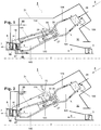
- Fig. 1 shows a gas turbine 1 with a sequential combustor arrangement 4. It comprises a compressor 3, a sequential combustor arrangement 4, and a turbine 5.
- the sequential combustor arrangement 4 comprises a first burner 106, a first combustion chamber 101, and a dilution gas admixer 27 for admixing a dilution gas 33 to the hot gases leaving the first combustion chamber 101 during operation. Downstream of the admixer 27 the sequential combustor arrangement 4 further comprises a second burner 103, and a second combustion chamber 102. The first burner 106, first combustion chamber 101, admixer 27, second burner 103 and second combustion chamber 102 are arranged sequentially in a fluid flow connection.
- the sequential combustor arrangement 4 is housed in a combustor casing 31.
- the compressed gas 8 leaving the compressor 3 passes through a diffusor for at least partly recovering the dynamic pressure of the gas leaving the compressor 3.
- the turbine 5 comprises vanes 11, and blades 10.
- the vanes 11 are cooled with cooling gas flowing through a closed loop cooling 17. Cooling gas is fed to the closed loop cooling 17 from the compressor plenum 30 through cooling gas feeds 22.
- a cooling gas feed 22 can for example be arranged in the compressor plenum 30 in a region between the rotor 2 and the combustor arrangement 4, or in a region between the combustor arrangement 4 and the combustor casing 31.
- Open loop cooling gas 13 can be discharged from the vane 11 into the hot gas flow.
- cooling gas which was heated in the closed loop cooling 17 is injected as dilution gas by the dilution gas admixer 27 into the first combustor combustion products 35.
- dilution gas injection 110 is used for the dilution gas admixing.
- the sequential combustor arrangement 4 further comprises a first combustor liner 104 for guiding cooling gas along the walls of the first combustion chamber, and a second combustor liner 105 for guiding cooling gas along the walls of the second combustion chamber 102.
- a first fuel 28 can be introduced into the first burner 106 via a first fuel injection, mixed with compressed gas 8 which is compressed in the compressor 3, and burned in the first combustion chamber 101. Dilution gas 33 is admixed in the subsequent admixer 27.
- a second fuel 29 can be introduced into the second burner 103 via a second fuel injector, mixed with hot gas leaving the admixer 27 and burned in the second combustion chamber 102. The hot gas leaving the second combustion chamber 102 is expanded in the subsequent turbine 5, performing work.
- the turbine 5 and compressor 3 are arranged on a rotor 2.
- the remaining heat of the exhaust gas 7 leaving the turbine 5 can be further used in a heat recovery steam generator or boiler (not shown) for steam generation.
- compressed gas 8 is admixed as dilution gas 33.
- compressed gas 8 is compressed ambient air.
- the compressor gas is a mixture of ambient air and recirculated flue gas.
- the gas turbine system includes a generator (not shown) which is coupled to a rotor 2 of the gas turbine 1.
- the gas turbine 1 further comprises a cooling system for the turbine 5, which is also not shown as it is not subject of the invention.
- the embodiment of Fig. 2 differs from the gas turbine of Fig. 1 in that the pressure of cooling gas returning from the closed loop cooling 17 of the second vane is boosted in a venturi nozzle 15 using compressed gas 8 from the compressor plenum as driving fluid 16 before it is fed into the admixer 27. Further, the cooling gas turbine from the first vane is used as cooling fluid to cool the walls of the second combustor liner 105 before it is fed into the admixer 27.
- Fig.2 further shows an additional dilution gas injection 33 upstream (with respect to the hot gases flowing through the combustor arrangement 4) of the location at which the heated cooling gas is injected in the admixer 27.
- Fig. 3 is also based on Fig. 1 . It differs from the gas turbine of Fig. 1 in that the admixer 27 comprises a streamlined body 32 for injecting dilution gas 33 into the first combustor combustion products. At least part of the dilution gas 33 is first introduced into the streamlined body 32 and injected into first combustor combustion products 35 from the streamlined body 32.
- the streamlined body 32 is arranged right at the entrance into the admixer 27.
- Embodiments in which the streamlined body 32 is arranged further downstream in the admixer 27 are also conceivable.
- the embodiment of Fig. 3 further comprises a closed loop cooling 17 for the first blade 10.
- Compressed gas 8 is fed via the blade cooling gas feed 12 to the closed loop cooling 17.
- the heated cooling gas returning from the first blade 10 is fed into the cooling channel of second combustor liner 105, flows along the second combustor liner 105 until it reaches the admixer 27 and is injected into the first combustor combustion products 35.
- the example further shows an injector pump 14 which is used to boost the pressure of the cooling gas returning from the closed loop cooling 17 of the second vane before it is injected via the admixer 27.
- Flame Sheet, EV, AEV or BEV burners can be used for can as well as for annular architectures.
- the mixing quality of the admixer II is crucial for a stable clean combustion since the burner system of the second combustion chamber 102 requires a prescribed inlet conditions.
- cooling gas and the dilution gas can be recooled in a cooling gas cooler before use as cooling gas, respectively as dilution gas.
Landscapes
- Engineering & Computer Science (AREA)
- Mechanical Engineering (AREA)
- General Engineering & Computer Science (AREA)
- Chemical & Material Sciences (AREA)
- Combustion & Propulsion (AREA)
- Turbine Rotor Nozzle Sealing (AREA)
Claims (15)
- Turbine à gaz (1) avec un compresseur (3), une turbine (5) et un agencement de chambre de combustion séquentiel (4) comprenant une première chambre de combustion avec un premier brûleur (106) pour introduire un premier combustible (28) dans un gaz d'entrée de chambre de combustion pendant l'opération et une première chambre de combustion (101) pour faire brûler le premier combustible (28), un mélangeur de gaz de dilution (27) pour mélanger un gaz de dilution (33) aux premiers produits de combustion de chambre de combustion (35) quittant la première chambre de combustion (101), un second brûleur (103) pour mélanger un second combustible (29) et une seconde chambre de combustion (102), dans laquelle la première chambre de combustion, le mélangeur de gaz de dilution (27), le second brûleur (103) et la seconde chambre de combustion (102) sont agencés, de manière séquentielle, dans un raccordement d'écoulement fluidique,
dans lequel une pale (11) et/ou une aube (10) de la turbine (5) présente un refroidissement en boucle fermée qui est raccordée à un plénum de compresseur (30) pour amener le fluide de refroidissement comprimé dans la pale (11) et/ou l'aube (10) et en ce que la sortie du refroidissement en boucle fermée (17) est raccordée au mélangeur de gaz de dilution (27) pour mélanger le gaz de refroidissement chauffé quittant la pale (11) et/ou l'aube (10) dans les premiers produits de combustion de chambre de combustion (35), caractérisée en ce que le second brûleur (103) et la seconde chambre de combustion (102) sont agencés en aval du mélangeur de gaz de dilution (27). - Turbine à gaz (1) selon la revendication 1, caractérisée en ce qu'elle comprend une alimentation en gaz de refroidissement (22) raccordant le plénum de compresseur (30) au refroidissement en boucle fermée (17).
- Turbine à gaz (1) selon la revendication 2, caractérisée en ce que l'alimentation en gaz de refroidissement (22) est agencée entre un rotor (2) de la turbine à gaz (1) et l'agencement de chambre de combustion séquentiel (4).
- Turbine à gaz (1) selon la revendication 2, caractérisée en ce que l'alimentation en gaz de refroidissement (22) passe entre un carter de chambre de combustion (31) de la turbine à gaz (1) et l'agencement de chambre de combustion séquentiel (4).
- Turbine à gaz (1) selon l'une des revendications 1 à 4, caractérisée en ce qu'un canal de refroidissement pour refroidir au moins l'un parmi un premier revêtement de combustion (104), un second revêtement de chambre de combustion (105), une paroi du second brûleur (103), une section de mélange (34) et un mélangeur de gaz de dilution (37) est intercalé entre la sortie du refroidissement en boucle fermée (17) et le mélangeur de gaz de dilution (27).
- Turbine à gaz (1) selon l'une des revendications 1 à 5, caractérisée en ce qu'une pompe d'éjection (15, 16) est intercalée entre la sortie du refroidissement en boucle fermée (17) et le mélangeur de gaz de dilution (27).
- Turbine à gaz (1) selon l'une des revendications 1 à 6, caractérisée en ce qu'au moins une alimentation vers le mélange de gaz de dilution (27) est directement raccordée au plénum de compresseur pour mélanger, de manière supplémentaire, le gaz de sortie de compresseur dans les premiers produits de combustion de chambre de combustion (35).
- Procédé pour actionner une turbine à gaz (1) avec un compresseur (3), une turbine (5) et un agencement de chambre de combustion séquentiel (4) avec une première chambre de combustion comprenant un premier brûleur (106) et une première chambre de combustion (101), un mélangeur de gaz de dilution (27), un second brûleur (103) et une seconde chambre de combustion (102), dans lequel la première chambre de combustion, le mélangeur de gaz de dilution (27), le second brûleur (103) et la seconde chambre de combustion (102) sont agencés de manière séquentielle dans un raccordement d'écoulement fluidique, le procédé comprenant les étapes consistant à :comprimer le gaz d'entrée dans le compresseur (3),mélanger un premier combustible (28) à au moins une partie du gaz comprimé dans le premier brûleur (106),faire brûler le mélange dans la première chambre de combustion (101) pour obtenir des premiers produits de combustion de chambre de combustion (35),mélanger le gaz de dilution avec les premiers produits de combustion de chambre de combustion quittant la première chambre de combustion (101) dans le mélangeur de gaz de dilution (27) ;dans lequel une pale (11) et/ou une aube (10) de la turbine (5) est refroidie avec un gaz comprimé (8) s'écoulant à travers un refroidissement en boucle fermée (17) de la pale (11) et/ou de l'aube (10), et en ce que le gaz de refroidissement chauffé quittant la pale (11) et/ou l'aube (10) est amené dans le mélangeur de gaz de dilution (27) et est mélangé dans les premiers produits de combustion de chambre de combustion (35) ;caractérisé en ce que le second brûleur (103) et la seconde chambre de combustion (102) sont agencés en aval du mélangeur de gaz de dilution (27) et le gaz de dilution est mélangé aux premiers produits de combustion de chambre de combustion quittant la première chambre de combustion (101) en amont du second brûleur (103) et de la seconde chambre de combustion.
- Procédé pour actionner une turbine à gaz (1) selon la revendication 8, caractérisé en ce que le gaz comprimé (8) est amené dans un refroidissement en boucle fermée (17) depuis le plénum de compresseur (30).
- Procédé pour actionner une turbine à gaz (1) selon la revendication 8, caractérisé en ce que le gaz comprimé (8) est alimenté dans le refroidissement en boucle fermée (17) à partir d'une alimentation en gaz de refroidissement (22) agencée dans le plénum de compresseur entre le rotor (2) et l'agencement de chambre de combustion séquentiel (4).
- Procédé pour actionner une turbine à gaz (1) selon la revendication 8, caractérisé en ce que le gaz comprimé (8) est amené au refroidissement en boucle fermée (17) à partir d'une alimentation en gaz de refroidissement (22) agencée dans le plénum de compresseur entre le carter de chambre de combustion (31) et l'agencement de chambre de combustion séquentiel (4).
- Procédé pour actionner une turbine à gaz (1) selon l'une des revendications 8 à 11, caractérisé en ce que le gaz de refroidissement quittant le refroidissement en boucle fermée (17) s'écoule à travers un canal de refroidissement pour refroidir au moins l'un parmi un premier revêtement de combustion (104), un second revêtement de combustion (105), une paroi du second brûleur (103), la section de mélange (34) et le mélangeur de gaz de dilution (37) avant qu'il ne soit amené dans le mélangeur de gaz de dilution (27).
- Procédé pour actionner une turbine à gaz (1) selon l'une des revendications 8 à 12, caractérisé en ce que la pression du gaz de refroidissement quittant le refroidissement en boucle fermée (17) est augmentée dans une pompe d'éjection (15, 16) avant que le gaz de refroidissement ne soit amené dans le mélangeur de gaz de dilution (27).
- Procédé pour actionner une turbine à gaz (1) selon la revendication 13, caractérisé en ce que le gaz comprimé (8) du plénum de compresseur (30) est utilisé pour mettre sous pression le gaz de refroidissement dans la pompe d'éjecteur (15, 16).
- Procédé pour actionner une turbine à gaz (1) selon l'une des revendications 8 à 14, caractérisé en ce que le gaz comprimé (8) directement prélevé à partir du plénum de compresseur (30) est mélangé dans les premiers produits de combustion de chambre de combustion (35) dans le mélangeur de gaz de dilution (27).
Priority Applications (5)
| Application Number | Priority Date | Filing Date | Title |
|---|---|---|---|
| EP15180787.2A EP3130848B1 (fr) | 2015-08-12 | 2015-08-12 | Dispositif à combustion séquentielle avec gaz de refroidissement pour la dilution |
| KR1020160101654A KR20170020248A (ko) | 2015-08-12 | 2016-08-10 | 희석을 위한 냉각 가스를 갖는 순차식 연소 장치 |
| US15/234,605 US10677453B2 (en) | 2015-08-12 | 2016-08-11 | Sequential combustion arrangement with cooling gas for dilution |
| CN201610659807.5A CN106468449B (zh) | 2015-08-12 | 2016-08-12 | 带有用于稀释的冷却气体的连续燃烧布置 |
| JP2016158870A JP2017040268A (ja) | 2015-08-12 | 2016-08-12 | 希釈用の冷却ガスを用いるシーケンシャル燃焼配列 |
Applications Claiming Priority (1)
| Application Number | Priority Date | Filing Date | Title |
|---|---|---|---|
| EP15180787.2A EP3130848B1 (fr) | 2015-08-12 | 2015-08-12 | Dispositif à combustion séquentielle avec gaz de refroidissement pour la dilution |
Publications (2)
| Publication Number | Publication Date |
|---|---|
| EP3130848A1 EP3130848A1 (fr) | 2017-02-15 |
| EP3130848B1 true EP3130848B1 (fr) | 2019-01-16 |
Family
ID=53900744
Family Applications (1)
| Application Number | Title | Priority Date | Filing Date |
|---|---|---|---|
| EP15180787.2A Active EP3130848B1 (fr) | 2015-08-12 | 2015-08-12 | Dispositif à combustion séquentielle avec gaz de refroidissement pour la dilution |
Country Status (5)
| Country | Link |
|---|---|
| US (1) | US10677453B2 (fr) |
| EP (1) | EP3130848B1 (fr) |
| JP (1) | JP2017040268A (fr) |
| KR (1) | KR20170020248A (fr) |
| CN (1) | CN106468449B (fr) |
Families Citing this family (3)
| Publication number | Priority date | Publication date | Assignee | Title |
|---|---|---|---|---|
| US11092076B2 (en) | 2017-11-28 | 2021-08-17 | General Electric Company | Turbine engine with combustor |
| EP3772616B1 (fr) * | 2019-08-08 | 2024-02-07 | Ansaldo Energia Switzerland AG | Procédé de fonctionnement d'un ensemble de turbine à gaz comprenant une chambre de combustion séquentielle |
| GB2596305A (en) * | 2020-06-23 | 2021-12-29 | Ansaldo Energia Switzerland AG | Burner of a reheat gas turbine engine |
Family Cites Families (12)
| Publication number | Priority date | Publication date | Assignee | Title |
|---|---|---|---|---|
| CH674561A5 (fr) | 1987-12-21 | 1990-06-15 | Bbc Brown Boveri & Cie | |
| DE19547913A1 (de) | 1995-12-21 | 1997-06-26 | Abb Research Ltd | Brenner für einen Wärmeerzeuger |
| JPH11241602A (ja) * | 1998-02-26 | 1999-09-07 | Toshiba Corp | ガスタービン翼 |
| US6523346B1 (en) * | 2001-11-02 | 2003-02-25 | Alstom (Switzerland) Ltd | Process for controlling the cooling air mass flow of a gas turbine set |
| DE10312971B4 (de) | 2003-03-24 | 2017-04-06 | General Electric Technology Gmbh | Verfahren zum Betreiben einer Gasturbogruppe |
| US6935116B2 (en) | 2003-04-28 | 2005-08-30 | Power Systems Mfg., Llc | Flamesheet combustor |
| US7237384B2 (en) | 2005-01-26 | 2007-07-03 | Peter Stuttaford | Counter swirl shear mixer |
| GB0920094D0 (en) * | 2009-11-17 | 2009-12-30 | Alstom Technology Ltd | Reheat combustor for a gas turbine engine |
| GB201015028D0 (en) * | 2010-09-10 | 2010-10-20 | Rolls Royce Plc | Gas turbine engine |
| WO2014001230A1 (fr) * | 2012-06-29 | 2014-01-03 | Alstom Technology Ltd | Procédé pour une opération de réduction de co de charge partielle pour une turbine à gaz séquentielle |
| KR20150047565A (ko) | 2012-08-24 | 2015-05-04 | 알스톰 테크놀러지 리미티드 | 희석 가스 혼합기를 갖는 연속 연소 |
| EP2722591A1 (fr) | 2012-10-22 | 2014-04-23 | Alstom Technology Ltd | Brûleur à multiples cones pour une turbine à gaz |
-
2015
- 2015-08-12 EP EP15180787.2A patent/EP3130848B1/fr active Active
-
2016
- 2016-08-10 KR KR1020160101654A patent/KR20170020248A/ko not_active Withdrawn
- 2016-08-11 US US15/234,605 patent/US10677453B2/en active Active
- 2016-08-12 CN CN201610659807.5A patent/CN106468449B/zh active Active
- 2016-08-12 JP JP2016158870A patent/JP2017040268A/ja active Pending
Non-Patent Citations (1)
| Title |
|---|
| None * |
Also Published As
| Publication number | Publication date |
|---|---|
| CN106468449A (zh) | 2017-03-01 |
| US20170045228A1 (en) | 2017-02-16 |
| US10677453B2 (en) | 2020-06-09 |
| EP3130848A1 (fr) | 2017-02-15 |
| KR20170020248A (ko) | 2017-02-22 |
| JP2017040268A (ja) | 2017-02-23 |
| CN106468449B (zh) | 2020-11-24 |
Similar Documents
| Publication | Publication Date | Title |
|---|---|---|
| US10634357B2 (en) | Sequential combustion with dilution gas mixer | |
| EP2894405B1 (fr) | Dispositif à combustion séquentielle avec un gaz de dilution | |
| EP2912381B1 (fr) | Combustion séquentielle avec mélangeur de gaz d'appoint | |
| US8281601B2 (en) | Systems and methods for reintroducing gas turbine combustion bypass flow | |
| EP2837889B1 (fr) | Combustion séquentielle avec un mélangeur de gaz de dilution | |
| US9708983B2 (en) | Gas turbine with sequential combustion arrangement | |
| US20170114717A1 (en) | Axial stage combustion system with exhaust gas recirculation | |
| US10222067B2 (en) | Combustor for a sequential gas turbine having a deflection unit between first and second combustion chambers | |
| EP2957835A1 (fr) | Procédé de recirculation des gaz d'échappement provenant d'une chambre de combustion d'un brûleur d'une turbine à gaz et turbine à gaz pour l'exécution de ce procédé | |
| CN103443542A (zh) | 燃气涡轮组件和对应的操作方法 | |
| EP2348256A1 (fr) | Procédé de fonctionnement d'une turbine à gaz et turbine à gaz | |
| US20140053569A1 (en) | Method for mixing a dilution air in a sequential combustion system of a gas turbine | |
| US20150107255A1 (en) | Turbomachine combustor having an externally fueled late lean injection (lli) system | |
| US10677453B2 (en) | Sequential combustion arrangement with cooling gas for dilution | |
| US20170058770A1 (en) | System and method for decoupling steam production dependency from gas turbine load level | |
| CN112344369A (zh) | 包括顺序燃烧器的燃气涡轮组件及其运行方法 |
Legal Events
| Date | Code | Title | Description |
|---|---|---|---|
| PUAI | Public reference made under article 153(3) epc to a published international application that has entered the european phase |
Free format text: ORIGINAL CODE: 0009012 |
|
| STAA | Information on the status of an ep patent application or granted ep patent |
Free format text: STATUS: THE APPLICATION HAS BEEN PUBLISHED |
|
| AK | Designated contracting states |
Kind code of ref document: A1 Designated state(s): AL AT BE BG CH CY CZ DE DK EE ES FI FR GB GR HR HU IE IS IT LI LT LU LV MC MK MT NL NO PL PT RO RS SE SI SK SM TR |
|
| AX | Request for extension of the european patent |
Extension state: BA ME |
|
| RAP1 | Party data changed (applicant data changed or rights of an application transferred) |
Owner name: ANSALDO ENERGIA SWITZERLAND AG |
|
| STAA | Information on the status of an ep patent application or granted ep patent |
Free format text: STATUS: REQUEST FOR EXAMINATION WAS MADE |
|
| 17P | Request for examination filed |
Effective date: 20170801 |
|
| RBV | Designated contracting states (corrected) |
Designated state(s): AL AT BE BG CH CY CZ DE DK EE ES FI FR GB GR HR HU IE IS IT LI LT LU LV MC MK MT NL NO PL PT RO RS SE SI SK SM TR |
|
| GRAP | Despatch of communication of intention to grant a patent |
Free format text: ORIGINAL CODE: EPIDOSNIGR1 |
|
| STAA | Information on the status of an ep patent application or granted ep patent |
Free format text: STATUS: GRANT OF PATENT IS INTENDED |
|
| RIC1 | Information provided on ipc code assigned before grant |
Ipc: F23C 6/04 20060101AFI20180706BHEP Ipc: F23R 3/34 20060101ALI20180706BHEP |
|
| INTG | Intention to grant announced |
Effective date: 20180808 |
|
| GRAS | Grant fee paid |
Free format text: ORIGINAL CODE: EPIDOSNIGR3 |
|
| GRAA | (expected) grant |
Free format text: ORIGINAL CODE: 0009210 |
|
| STAA | Information on the status of an ep patent application or granted ep patent |
Free format text: STATUS: THE PATENT HAS BEEN GRANTED |
|
| AK | Designated contracting states |
Kind code of ref document: B1 Designated state(s): AL AT BE BG CH CY CZ DE DK EE ES FI FR GB GR HR HU IE IS IT LI LT LU LV MC MK MT NL NO PL PT RO RS SE SI SK SM TR |
|
| REG | Reference to a national code |
Ref country code: GB Ref legal event code: FG4D |
|
| REG | Reference to a national code |
Ref country code: CH Ref legal event code: EP |
|
| REG | Reference to a national code |
Ref country code: IE Ref legal event code: FG4D |
|
| REG | Reference to a national code |
Ref country code: DE Ref legal event code: R096 Ref document number: 602015023518 Country of ref document: DE |
|
| REG | Reference to a national code |
Ref country code: AT Ref legal event code: REF Ref document number: 1089951 Country of ref document: AT Kind code of ref document: T Effective date: 20190215 |
|
| REG | Reference to a national code |
Ref country code: NL Ref legal event code: MP Effective date: 20190116 |
|
| REG | Reference to a national code |
Ref country code: LT Ref legal event code: MG4D |
|
| PG25 | Lapsed in a contracting state [announced via postgrant information from national office to epo] |
Ref country code: NL Free format text: LAPSE BECAUSE OF FAILURE TO SUBMIT A TRANSLATION OF THE DESCRIPTION OR TO PAY THE FEE WITHIN THE PRESCRIBED TIME-LIMIT Effective date: 20190116 |
|
| REG | Reference to a national code |
Ref country code: AT Ref legal event code: MK05 Ref document number: 1089951 Country of ref document: AT Kind code of ref document: T Effective date: 20190116 |
|
| PG25 | Lapsed in a contracting state [announced via postgrant information from national office to epo] |
Ref country code: PL Free format text: LAPSE BECAUSE OF FAILURE TO SUBMIT A TRANSLATION OF THE DESCRIPTION OR TO PAY THE FEE WITHIN THE PRESCRIBED TIME-LIMIT Effective date: 20190116 Ref country code: NO Free format text: LAPSE BECAUSE OF FAILURE TO SUBMIT A TRANSLATION OF THE DESCRIPTION OR TO PAY THE FEE WITHIN THE PRESCRIBED TIME-LIMIT Effective date: 20190416 Ref country code: SE Free format text: LAPSE BECAUSE OF FAILURE TO SUBMIT A TRANSLATION OF THE DESCRIPTION OR TO PAY THE FEE WITHIN THE PRESCRIBED TIME-LIMIT Effective date: 20190116 Ref country code: FI Free format text: LAPSE BECAUSE OF FAILURE TO SUBMIT A TRANSLATION OF THE DESCRIPTION OR TO PAY THE FEE WITHIN THE PRESCRIBED TIME-LIMIT Effective date: 20190116 Ref country code: PT Free format text: LAPSE BECAUSE OF FAILURE TO SUBMIT A TRANSLATION OF THE DESCRIPTION OR TO PAY THE FEE WITHIN THE PRESCRIBED TIME-LIMIT Effective date: 20190516 Ref country code: ES Free format text: LAPSE BECAUSE OF FAILURE TO SUBMIT A TRANSLATION OF THE DESCRIPTION OR TO PAY THE FEE WITHIN THE PRESCRIBED TIME-LIMIT Effective date: 20190116 Ref country code: LT Free format text: LAPSE BECAUSE OF FAILURE TO SUBMIT A TRANSLATION OF THE DESCRIPTION OR TO PAY THE FEE WITHIN THE PRESCRIBED TIME-LIMIT Effective date: 20190116 |
|
| PG25 | Lapsed in a contracting state [announced via postgrant information from national office to epo] |
Ref country code: LV Free format text: LAPSE BECAUSE OF FAILURE TO SUBMIT A TRANSLATION OF THE DESCRIPTION OR TO PAY THE FEE WITHIN THE PRESCRIBED TIME-LIMIT Effective date: 20190116 Ref country code: HR Free format text: LAPSE BECAUSE OF FAILURE TO SUBMIT A TRANSLATION OF THE DESCRIPTION OR TO PAY THE FEE WITHIN THE PRESCRIBED TIME-LIMIT Effective date: 20190116 Ref country code: GR Free format text: LAPSE BECAUSE OF FAILURE TO SUBMIT A TRANSLATION OF THE DESCRIPTION OR TO PAY THE FEE WITHIN THE PRESCRIBED TIME-LIMIT Effective date: 20190417 Ref country code: IS Free format text: LAPSE BECAUSE OF FAILURE TO SUBMIT A TRANSLATION OF THE DESCRIPTION OR TO PAY THE FEE WITHIN THE PRESCRIBED TIME-LIMIT Effective date: 20190516 Ref country code: BG Free format text: LAPSE BECAUSE OF FAILURE TO SUBMIT A TRANSLATION OF THE DESCRIPTION OR TO PAY THE FEE WITHIN THE PRESCRIBED TIME-LIMIT Effective date: 20190416 Ref country code: RS Free format text: LAPSE BECAUSE OF FAILURE TO SUBMIT A TRANSLATION OF THE DESCRIPTION OR TO PAY THE FEE WITHIN THE PRESCRIBED TIME-LIMIT Effective date: 20190116 |
|
| REG | Reference to a national code |
Ref country code: DE Ref legal event code: R097 Ref document number: 602015023518 Country of ref document: DE |
|
| PG25 | Lapsed in a contracting state [announced via postgrant information from national office to epo] |
Ref country code: AL Free format text: LAPSE BECAUSE OF FAILURE TO SUBMIT A TRANSLATION OF THE DESCRIPTION OR TO PAY THE FEE WITHIN THE PRESCRIBED TIME-LIMIT Effective date: 20190116 Ref country code: DK Free format text: LAPSE BECAUSE OF FAILURE TO SUBMIT A TRANSLATION OF THE DESCRIPTION OR TO PAY THE FEE WITHIN THE PRESCRIBED TIME-LIMIT Effective date: 20190116 Ref country code: EE Free format text: LAPSE BECAUSE OF FAILURE TO SUBMIT A TRANSLATION OF THE DESCRIPTION OR TO PAY THE FEE WITHIN THE PRESCRIBED TIME-LIMIT Effective date: 20190116 Ref country code: CZ Free format text: LAPSE BECAUSE OF FAILURE TO SUBMIT A TRANSLATION OF THE DESCRIPTION OR TO PAY THE FEE WITHIN THE PRESCRIBED TIME-LIMIT Effective date: 20190116 Ref country code: AT Free format text: LAPSE BECAUSE OF FAILURE TO SUBMIT A TRANSLATION OF THE DESCRIPTION OR TO PAY THE FEE WITHIN THE PRESCRIBED TIME-LIMIT Effective date: 20190116 Ref country code: IT Free format text: LAPSE BECAUSE OF FAILURE TO SUBMIT A TRANSLATION OF THE DESCRIPTION OR TO PAY THE FEE WITHIN THE PRESCRIBED TIME-LIMIT Effective date: 20190116 Ref country code: SK Free format text: LAPSE BECAUSE OF FAILURE TO SUBMIT A TRANSLATION OF THE DESCRIPTION OR TO PAY THE FEE WITHIN THE PRESCRIBED TIME-LIMIT Effective date: 20190116 Ref country code: RO Free format text: LAPSE BECAUSE OF FAILURE TO SUBMIT A TRANSLATION OF THE DESCRIPTION OR TO PAY THE FEE WITHIN THE PRESCRIBED TIME-LIMIT Effective date: 20190116 |
|
| PLBE | No opposition filed within time limit |
Free format text: ORIGINAL CODE: 0009261 |
|
| STAA | Information on the status of an ep patent application or granted ep patent |
Free format text: STATUS: NO OPPOSITION FILED WITHIN TIME LIMIT |
|
| PG25 | Lapsed in a contracting state [announced via postgrant information from national office to epo] |
Ref country code: SM Free format text: LAPSE BECAUSE OF FAILURE TO SUBMIT A TRANSLATION OF THE DESCRIPTION OR TO PAY THE FEE WITHIN THE PRESCRIBED TIME-LIMIT Effective date: 20190116 |
|
| 26N | No opposition filed |
Effective date: 20191017 |
|
| PG25 | Lapsed in a contracting state [announced via postgrant information from national office to epo] |
Ref country code: SI Free format text: LAPSE BECAUSE OF FAILURE TO SUBMIT A TRANSLATION OF THE DESCRIPTION OR TO PAY THE FEE WITHIN THE PRESCRIBED TIME-LIMIT Effective date: 20190116 |
|
| PG25 | Lapsed in a contracting state [announced via postgrant information from national office to epo] |
Ref country code: TR Free format text: LAPSE BECAUSE OF FAILURE TO SUBMIT A TRANSLATION OF THE DESCRIPTION OR TO PAY THE FEE WITHIN THE PRESCRIBED TIME-LIMIT Effective date: 20190116 |
|
| GBPC | Gb: european patent ceased through non-payment of renewal fee |
Effective date: 20190812 |
|
| PG25 | Lapsed in a contracting state [announced via postgrant information from national office to epo] |
Ref country code: MC Free format text: LAPSE BECAUSE OF FAILURE TO SUBMIT A TRANSLATION OF THE DESCRIPTION OR TO PAY THE FEE WITHIN THE PRESCRIBED TIME-LIMIT Effective date: 20190116 Ref country code: LI Free format text: LAPSE BECAUSE OF NON-PAYMENT OF DUE FEES Effective date: 20190831 Ref country code: CH Free format text: LAPSE BECAUSE OF NON-PAYMENT OF DUE FEES Effective date: 20190831 Ref country code: LU Free format text: LAPSE BECAUSE OF NON-PAYMENT OF DUE FEES Effective date: 20190812 |
|
| REG | Reference to a national code |
Ref country code: BE Ref legal event code: MM Effective date: 20190831 |
|
| PG25 | Lapsed in a contracting state [announced via postgrant information from national office to epo] |
Ref country code: IE Free format text: LAPSE BECAUSE OF NON-PAYMENT OF DUE FEES Effective date: 20190812 Ref country code: FR Free format text: LAPSE BECAUSE OF NON-PAYMENT OF DUE FEES Effective date: 20190831 |
|
| PG25 | Lapsed in a contracting state [announced via postgrant information from national office to epo] |
Ref country code: BE Free format text: LAPSE BECAUSE OF NON-PAYMENT OF DUE FEES Effective date: 20190831 Ref country code: GB Free format text: LAPSE BECAUSE OF NON-PAYMENT OF DUE FEES Effective date: 20190812 |
|
| PG25 | Lapsed in a contracting state [announced via postgrant information from national office to epo] |
Ref country code: CY Free format text: LAPSE BECAUSE OF FAILURE TO SUBMIT A TRANSLATION OF THE DESCRIPTION OR TO PAY THE FEE WITHIN THE PRESCRIBED TIME-LIMIT Effective date: 20190116 |
|
| PG25 | Lapsed in a contracting state [announced via postgrant information from national office to epo] |
Ref country code: MT Free format text: LAPSE BECAUSE OF FAILURE TO SUBMIT A TRANSLATION OF THE DESCRIPTION OR TO PAY THE FEE WITHIN THE PRESCRIBED TIME-LIMIT Effective date: 20190116 Ref country code: HU Free format text: LAPSE BECAUSE OF FAILURE TO SUBMIT A TRANSLATION OF THE DESCRIPTION OR TO PAY THE FEE WITHIN THE PRESCRIBED TIME-LIMIT; INVALID AB INITIO Effective date: 20150812 |
|
| PG25 | Lapsed in a contracting state [announced via postgrant information from national office to epo] |
Ref country code: MK Free format text: LAPSE BECAUSE OF FAILURE TO SUBMIT A TRANSLATION OF THE DESCRIPTION OR TO PAY THE FEE WITHIN THE PRESCRIBED TIME-LIMIT Effective date: 20190116 |
|
| P01 | Opt-out of the competence of the unified patent court (upc) registered |
Effective date: 20240430 |
|
| PGFP | Annual fee paid to national office [announced via postgrant information from national office to epo] |
Ref country code: DE Payment date: 20250819 Year of fee payment: 11 |