EP3130855A1 - Agencement de trou de chambre de combustion pour moteur à turbine à gaz - Google Patents
Agencement de trou de chambre de combustion pour moteur à turbine à gaz Download PDFInfo
- Publication number
- EP3130855A1 EP3130855A1 EP16184221.6A EP16184221A EP3130855A1 EP 3130855 A1 EP3130855 A1 EP 3130855A1 EP 16184221 A EP16184221 A EP 16184221A EP 3130855 A1 EP3130855 A1 EP 3130855A1
- Authority
- EP
- European Patent Office
- Prior art keywords
- combustor
- airflow injection
- airflow
- injection holes
- liner
- Prior art date
- Legal status (The legal status is an assumption and is not a legal conclusion. Google has not performed a legal analysis and makes no representation as to the accuracy of the status listed.)
- Granted
Links
Images


Classifications
-
- F—MECHANICAL ENGINEERING; LIGHTING; HEATING; WEAPONS; BLASTING
- F23—COMBUSTION APPARATUS; COMBUSTION PROCESSES
- F23R—GENERATING COMBUSTION PRODUCTS OF HIGH PRESSURE OR HIGH VELOCITY, e.g. GAS-TURBINE COMBUSTION CHAMBERS
- F23R3/00—Continuous combustion chambers using liquid or gaseous fuel
- F23R3/002—Wall structures
-
- F—MECHANICAL ENGINEERING; LIGHTING; HEATING; WEAPONS; BLASTING
- F23—COMBUSTION APPARATUS; COMBUSTION PROCESSES
- F23R—GENERATING COMBUSTION PRODUCTS OF HIGH PRESSURE OR HIGH VELOCITY, e.g. GAS-TURBINE COMBUSTION CHAMBERS
- F23R3/00—Continuous combustion chambers using liquid or gaseous fuel
- F23R3/02—Continuous combustion chambers using liquid or gaseous fuel characterised by the air-flow or gas-flow configuration
- F23R3/04—Air inlet arrangements
- F23R3/06—Arrangement of apertures along the flame tube
-
- F—MECHANICAL ENGINEERING; LIGHTING; HEATING; WEAPONS; BLASTING
- F23—COMBUSTION APPARATUS; COMBUSTION PROCESSES
- F23R—GENERATING COMBUSTION PRODUCTS OF HIGH PRESSURE OR HIGH VELOCITY, e.g. GAS-TURBINE COMBUSTION CHAMBERS
- F23R3/00—Continuous combustion chambers using liquid or gaseous fuel
- F23R3/42—Continuous combustion chambers using liquid or gaseous fuel characterised by the arrangement or form of the flame tubes or combustion chambers
- F23R3/50—Combustion chambers comprising an annular flame tube within an annular casing
Definitions
- This disclosure relates to gas turbine engines, and more particularly to combustor airflow hole arrangements for gas turbine engines.
- Combustor air exit temperature is a significant driver of gas turbine engine performance and design.
- Components downstream of the combustor such as the turbine and turbine blades, are configured for use with particular temperature ranges. Spacing and arrangement of airflow holes in the combustor are a key driver of combustor exit temperature. Sufficient airflow must reach the combustion chamber of the combustor through these airflow holes, thus reducing the temperature of combustion gases to a desired temperature range.
- the airflow holes must also be arranged to allow for cooling airflow to flow across the combustor itself, to cool the combustor and extend the combustor service life.
- a combustor liner for a gas turbine comprises a wall and a plurality of airflow injection holes in the wall arranged in a circumferentially-extending row, the plurality of airflow injection holes including a plurality of circular first airflow injection holes and at least one non-circular second airflow injection hole.
- further embodiments may include that the plurality of airflow injection holes is an alternating arrangement of first airflow injection holes and second airflow injection holes.
- further embodiments may include that the second airflow injection hole has an aspect ratio of axial length to circumferential width of greater than or equal to two.
- further embodiments may include that the aspect ratio is between two and six.
- further embodiments may include that the second airflow injection hole is one of elliptically-shaped, diamond-shaped or oval-shaped.
- further embodiments may include that a ratio of a material width between adjacent first airflow injection holes and second airflow injection holes to a radius of the wall is greater than or equal to 0.030.
- further embodiments may include that a ratio of first airflow injection hole diameter and second airflow injection hole circumferential width is between 3 and 12.
- a combustor for a gas turbine engine includes a combustor case and a combustor liner disposed in the combustor case, radially offset from the combustor case to define an airflow pathway between the combustor case and the combustor liner.
- the combustor liner includes a wall and a plurality of airflow injection holes in the wall arranged in a circumferentially-extending row, the plurality of airflow injection holes including a plurality of circular first airflow injection holes and at least one non-circular second airflow injection hole, the plurality of airflow injection holes configured to reduce a temperature of combustion gases exiting the combustor.
- further embodiments may include one or more fuel injectors extending through the combustor liner and into the combustion zone, providing a flow of fuel for combustion in the combustion zone.
- further embodiments may include that the plurality of airflow injection holes is an alternating arrangement of first airflow injection holes and second airflow injection holes.
- further embodiments may include that the second airflow injection hole has an aspect ratio of axial length to circumferential width of greater than or equal to two.
- further embodiments may include that the aspect ratio is between two and six.
- further embodiments may include that the second airflow injection hole is one of elliptically-shaped, diamond-shaped or oval-shaped.
- further embodiments may include that a ratio of a material width between adjacent first airflow injection holes and second airflow injection holes to a radius of the wall is greater than or equal to 0.030.
- further embodiments may include that a ratio of first airflow injection hole diameter and second airflow injection hole circumferential width is between 3 and 12.
- a gas turbine engine includes a turbine and a combustor operably connected to the turbine, the combustor driving the turbine via combustion products of the combustor.
- the combustor includes a combustor case and a combustor liner disposed in the combustor case, radially offset from the combustor case to define an airflow pathway between the combustor case and the combustor liner.
- the combustor liner includes a wall and the wall including a plurality of airflow injection holes arranged in a circumferentially-extending row, the plurality of airflow injection holes including a plurality of circular first airflow injection holes and at least one non-circular second airflow injection hole, the plurality of airflow injection holes configured to reduce a temperature of combustion gases exiting the combustor.
- further embodiments may include one or more fuel injectors extending through the combustor liner and into the combustion zone, providing a flow of fuel for combustion in the combustion zone.
- further embodiments may include that the plurality of airflow injection holes is an alternating arrangement of first airflow injection holes and second airflow injection holes.
- further embodiments may include that the second airflow injection hole has an aspect ratio of axial length to circumferential width of greater than or equal to two.
- further embodiments may include that the aspect ratio is between two and six.
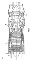
- FIG. 1 is a schematic illustration of an exemplary gas turbine engine 10 capable of using features of the present disclosure. While a turbojet gas turbine engine 10 is illustrated, it is to be appreciated that the present disclosure may be utilized with other gas turbine engine configurations such as, but not limited to, turbo prop, turbo fan (geared or conventional), or industrial gas turbine engines.
- the gas turbine engine 10 generally has a fan 12 through which ambient air is propelled in the direction of arrow 14, a compressor 16 for pressurizing the air received from the fan 12 and a combustor 18 wherein the compressed air is mixed with fuel and ignited for generating combustion gases.
- the gas turbine engine 10 further comprises a turbine section 20 for extracting energy from the combustion gases. Fuel is injected into the combustor 18 of the gas turbine engine 10 for mixing with the compressed air from the compressor 16 and ignition of the resultant mixture.
- the fan 12, compressor 16, combustor 18, and turbine 20 are typically all concentric about a common central longitudinal axis of the gas turbine engine 10.
- the gas turbine engine 10 may further comprise a low pressure compressor located in front of a high pressure compressor and a high pressure turbine located in front of a low pressure turbine.
- the compressor 16 may be a multi-stage compressor 16 that has a low-pressure compressor and a high-pressure compressor and the turbine 20 may be a multistage turbine 20 that has a high-pressure turbine and a low-pressure turbine.
- the low-pressure compressor is connected to the low-pressure turbine and the high pressure compressor is connected to the high-pressure turbine.
- a gear arrangement (not shown) connects the fan 12 and compressor 16 so the fan 12 and compressor 16 to allow for the fan 12 and compressor 16 to have different rotational speeds.
- FIG. 2 Shown in FIG. 2 is a schematic view of an exemplary combustor 18.
- the combustor 18 can have an annular structure including a combustor case 22 that houses a combustor liner 24.
- the combustor liner 24 is offset from the combustor case 22 to define an outer airflow path 26 between the combustor liner 24 and the combustor case 22. While and annular combustor 18 is illustrated, one skilled in the art will appreciate that the present disclosure may be applicable to other combustor configurations, such as can-annular combustors.
- the combustor liner 24 comprises an axially-extending outer wall 62 and an axially extending inner wall 64 that each extend circumferentially around the combustor 18.
- a radial offset between the outer wall 62 and the inner wall 64 defines a combustion zone 28 inside of the combustor liner 24 where a fuel and air mixture is combusted.
- a fuel flow 36 is delivered to the combustion zone 28 via one or more fuel injectors 30, while a primary airflow 32 is delivered to the combustion zone 28 through, for example, a swirler 34, which enhances mixing of the primary airflow 32 and the fuel flow 36 prior to combustion.
- An igniter 38 may be utilized to initiate combustion in the combustion zone 28. While a single combustion zone 28 is shown in FIG. 2 , it is to be appreciated that multiple combustion zones 28 may be arranged circumferentially around the combustor 18.
- the primary airflow 32 is received at the combustor 18 from the compressor via a diffuser 66.
- Primary airflow 32 not flowed into the combustion zone 28 via the swirler 34 may be diverted into the outer airflow path 26 as a secondary airflow 40.
- the combustor liner 24 includes a plurality of airflow injection holes 42. Via the airflow injection holes 42, secondary airflow 40 is directed into the combustion zone 28 to mix with combustion gases 44 as the combustion gases 44 flow toward the turbine 20. Since the secondary airflow 40 is lower in temperature than combustion gases 44 in the combustion zone 28, the addition of the secondary airflow 40 to the combustion gases 44 reduces the temperature of the combustion gases 44 to a selected temperature or selected temperature range. The degree of temperature reduction depends, at least in part, on the volume of secondary airflow 40 mixed with the combustion gases 44. The secondary airflow 40 volume, in turn, depends on a total open area of the airflow injection holes 42.
- the combustor liner 24 additionally includes cooling flow holes 46.
- the cooling flow holes 46 are generally smaller in open area than the airflow injection holes 42 and direct a cooling airflow 48 from the outer airflow path 26 through the combustor liner 24.
- the cooling airflow 48 forms a cooling film on an inner liner surface 52, as well as other liner surfaces, such as an outer diameter and bulkhead, to cool the combustor liner 24 and protect the combustor liner 24 from the extreme high temperature of the combustion gases 44.
- the airflow injection holes 42 should be configured and arranged to support formation of the cooling film.
- the combustor liner 24 includes the plurality of airflow injection holes 42 and the plurality of cooling flow holes 46.
- the airflow injection holes 42 are arranged in axially-spaced rows extending circumferentially around the combustor liner 24.
- Each row of airflow injection holes 42 includes airflow injection holes 42 of at least two different perimetrical shapes.
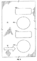
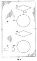
- the row includes an alternating arrangement of circular airflow injection holes 42a and axially-elongated airflow injection holes 42b, the axially-elongated airflow injection holes 42b elongated along a general airflow direction 54 through the combustor 18.
- the circular airflow injection holes 42a may be offset in a streamwise direction from the axially-elongated airflow injection holes 42b.
- the axially-elongated airflow injection holes 42b are elliptical (shown in FIG. 4 ), while in other embodiments other shapes such as oval (shown in FIG. 5 ), diamond-shaped (shown in FIG. 6 ), rectangular, or other shape may be utilized.
- the axially-elongated airflow injection holes 42b have a circumferential width 56 and an axial length 58 greater than the circumferential width 56. In some embodiments, an aspect ratio of axial length 58 to circumferential width 56 is between 2 and 6.
- the axially-elongated airflow injection holes 42b are configured to allow a secondary airflow 40 through each axially-elongated airflow injection hole 42b substantially equal to the secondary airflow 40 through each circular airflow injection hole 42a.
- an area of each axially-elongated airflow injection hole 42b is equal to an area of each circular airflow injection hole 42a.
- the arrangement of alternating circular and elongated airflow injection holes 42 increases a material width 60 between the airflow injection holes 42, compared to arrangements with large circular holes alternating with small circular holes. That is, the amount of material (material width 60) between two adjacent injection holes may be increased as comparted to having only circular holes.
- the increased material width 60 increases a surface area of the inner liner surface 52 to better support formation of a cooling film.
- the cooling airflow material width 60 close to minimize gaps through which combustion gases from the primary zone (front end) of the combustor 18 can escape without diluting with the air from the airflow injection holes 42. While having large circular holes alternating with small circular holes would accomplish this, it would impact the combustor life because there is no space left in between the large and small airflow injection holes when accounting for panel grommets to put cooling holes in the combustor liner. To meet both requirements (exit temperature quality and combustor life) the spacing between the airflow injection holes 42 needs to be minimized and enough room needs to be left to put cooling holes in the liner.
- a ratio of the material width 60 i.e., the width or distance of material between two adjacent injection holes 42a, 42b, to the radius of the liner wall (62, 64) may be 0.030 or greater.
- a ratio of the circular hole diameter 66 to elongated hole circumferential width 56 may be between 3 and 12.
Landscapes
- Engineering & Computer Science (AREA)
- Chemical & Material Sciences (AREA)
- Combustion & Propulsion (AREA)
- Mechanical Engineering (AREA)
- General Engineering & Computer Science (AREA)
- Turbine Rotor Nozzle Sealing (AREA)
Applications Claiming Priority (1)
| Application Number | Priority Date | Filing Date | Title |
|---|---|---|---|
| US14/826,463 US10670267B2 (en) | 2015-08-14 | 2015-08-14 | Combustor hole arrangement for gas turbine engine |
Publications (2)
| Publication Number | Publication Date |
|---|---|
| EP3130855A1 true EP3130855A1 (fr) | 2017-02-15 |
| EP3130855B1 EP3130855B1 (fr) | 2022-06-15 |
Family
ID=56686709
Family Applications (1)
| Application Number | Title | Priority Date | Filing Date |
|---|---|---|---|
| EP16184221.6A Active EP3130855B1 (fr) | 2015-08-14 | 2016-08-15 | Paroi de chambre de combustion de turbine à gaz comprenant une agencement de perforations |
Country Status (2)
| Country | Link |
|---|---|
| US (1) | US10670267B2 (fr) |
| EP (1) | EP3130855B1 (fr) |
Families Citing this family (5)
| Publication number | Priority date | Publication date | Assignee | Title |
|---|---|---|---|---|
| GB201518345D0 (en) * | 2015-10-16 | 2015-12-02 | Rolls Royce | Combustor for a gas turbine engine |
| US11181269B2 (en) * | 2018-11-15 | 2021-11-23 | General Electric Company | Involute trapped vortex combustor assembly |
| US11248789B2 (en) | 2018-12-07 | 2022-02-15 | Raytheon Technologies Corporation | Gas turbine engine with integral combustion liner and turbine nozzle |
| US11920790B2 (en) | 2021-11-03 | 2024-03-05 | General Electric Company | Wavy annular dilution slots for lower emissions |
| CN116221774B (zh) * | 2021-12-06 | 2025-09-09 | 通用电气公司 | 用于燃烧器衬里的变化的稀释孔设计 |
Citations (4)
| Publication number | Priority date | Publication date | Assignee | Title |
|---|---|---|---|---|
| EP1632720A1 (fr) * | 2004-09-03 | 2006-03-08 | General Electric Company | Réglage du débit d'air dans un élément de turbine par dépôt d'une couche superficielle métallique |
| WO2010081941A1 (fr) * | 2009-01-19 | 2010-07-22 | Snecma | Paroi de chambre de combustion de turbomachine à une seule rangée annulaire d'orifices d'entrée d'air primaire et de dilution |
| WO2012114030A1 (fr) * | 2011-02-25 | 2012-08-30 | Snecma | Chambre annulaire de combustion de turbomachine comprenant des orifices de dilution ameliores |
| WO2014149081A1 (fr) * | 2013-03-15 | 2014-09-25 | Rolls-Royce Corporation | Chambre de combustion à doublet de contre-tourbillon |
Family Cites Families (22)
| Publication number | Priority date | Publication date | Assignee | Title |
|---|---|---|---|---|
| US2543755A (en) * | 1946-07-25 | 1951-03-06 | Westinghouse Electric Corp | Air inlet opening arrangement for combustion chambers |
| BE652833A (fr) * | 1963-09-16 | |||
| US4733538A (en) * | 1978-10-02 | 1988-03-29 | General Electric Company | Combustion selective temperature dilution |
| FR2727193B1 (fr) * | 1994-11-23 | 1996-12-20 | Snecma | Chambre de combustion a deux tetes fonctionnant du ralenti au plein gaz |
| US6260359B1 (en) * | 1999-11-01 | 2001-07-17 | General Electric Company | Offset dilution combustor liner |
| US6513331B1 (en) * | 2001-08-21 | 2003-02-04 | General Electric Company | Preferential multihole combustor liner |
| US6792757B2 (en) * | 2002-11-05 | 2004-09-21 | Honeywell International Inc. | Gas turbine combustor heat shield impingement cooling baffle |
| FR2892180B1 (fr) * | 2005-10-18 | 2008-02-01 | Snecma Sa | Amelioration des perfomances d'une chambre de combustion par multiperforation des parois |
| US7895841B2 (en) * | 2006-07-14 | 2011-03-01 | General Electric Company | Method and apparatus to facilitate reducing NOx emissions in turbine engines |
| US7669422B2 (en) * | 2006-07-26 | 2010-03-02 | General Electric Company | Combustor liner and method of fabricating same |
| US7926284B2 (en) * | 2006-11-30 | 2011-04-19 | Honeywell International Inc. | Quench jet arrangement for annular rich-quench-lean gas turbine combustors |
| DE102007018061A1 (de) * | 2007-04-17 | 2008-10-23 | Rolls-Royce Deutschland Ltd & Co Kg | Gasturbinenbrennkammerwand |
| US20090142548A1 (en) * | 2007-10-18 | 2009-06-04 | David Bruce Patterson | Air cooled gas turbine components and methods of manufacturing and repairing the same |
| US8091367B2 (en) * | 2008-09-26 | 2012-01-10 | Pratt & Whitney Canada Corp. | Combustor with improved cooling holes arrangement |
| US8141365B2 (en) * | 2009-02-27 | 2012-03-27 | Honeywell International Inc. | Plunged hole arrangement for annular rich-quench-lean gas turbine combustors |
| FR2948988B1 (fr) * | 2009-08-04 | 2011-12-09 | Snecma | Chambre de combustion de turbomachine comprenant des orifices d'entree d'air ameliores |
| US7887100B1 (en) * | 2009-12-08 | 2011-02-15 | Car Sound Exhaust Systems, Inc | Method and apparatus for mating irregular or non-circular exhaust ports with tubing of a circular cross section in exhaust flange assemblies |
| US9041492B2 (en) * | 2011-04-29 | 2015-05-26 | Massachusetts Institute Of Technology | Unreleased mems resonator and method of forming same |
| FR2975465B1 (fr) * | 2011-05-19 | 2018-03-09 | Safran Aircraft Engines | Paroi pour chambre de combustion de turbomachine comprenant un agencement optimise d'orifices d'entree d'air |
| DE102011114928A1 (de) | 2011-10-06 | 2013-04-11 | Lufthansa Technik Ag | Brennkammer für eine Gasturbine |
| US20140216044A1 (en) * | 2012-12-17 | 2014-08-07 | United Technologoes Corporation | Gas turbine engine combustor heat shield with increased film cooling effectiveness |
| WO2014123850A1 (fr) * | 2013-02-06 | 2014-08-14 | United Technologies Corporation | Composant de turbine à gaz avec trous de film de refroidissement orientés vers l'amont |
-
2015
- 2015-08-14 US US14/826,463 patent/US10670267B2/en active Active
-
2016
- 2016-08-15 EP EP16184221.6A patent/EP3130855B1/fr active Active
Patent Citations (4)
| Publication number | Priority date | Publication date | Assignee | Title |
|---|---|---|---|---|
| EP1632720A1 (fr) * | 2004-09-03 | 2006-03-08 | General Electric Company | Réglage du débit d'air dans un élément de turbine par dépôt d'une couche superficielle métallique |
| WO2010081941A1 (fr) * | 2009-01-19 | 2010-07-22 | Snecma | Paroi de chambre de combustion de turbomachine à une seule rangée annulaire d'orifices d'entrée d'air primaire et de dilution |
| WO2012114030A1 (fr) * | 2011-02-25 | 2012-08-30 | Snecma | Chambre annulaire de combustion de turbomachine comprenant des orifices de dilution ameliores |
| WO2014149081A1 (fr) * | 2013-03-15 | 2014-09-25 | Rolls-Royce Corporation | Chambre de combustion à doublet de contre-tourbillon |
Also Published As
| Publication number | Publication date |
|---|---|
| EP3130855B1 (fr) | 2022-06-15 |
| US20170045226A1 (en) | 2017-02-16 |
| US10670267B2 (en) | 2020-06-02 |
Similar Documents
| Publication | Publication Date | Title |
|---|---|---|
| US10072846B2 (en) | Trapped vortex cavity staging in a combustor | |
| EP2904238B1 (fr) | Refroidissement de chemises de chambre de combustion avec des canaux d'accélération | |
| JP5374031B2 (ja) | タービンエンジンにおけるNOxエミッションを低減するのを可能にするための装置及びガスタービンエンジン | |
| US9376985B2 (en) | Ovate swirler assembly for combustors | |
| KR102175869B1 (ko) | 가스 터빈 엔진용 제트 스월 에어 블라스트 연료 인젝터 | |
| EP2224170B1 (fr) | Agencement d'ouvertures à collerette pour chambres de combustion annulaire pour turbine à gaz du type riche-trempe-pauvre | |
| EP2932157B1 (fr) | Ensemble coupelle rotative oblongue pour chambres de combustion | |
| US20090113893A1 (en) | Pilot mixer for mixer assembly of a gas turbine engine combustor having a primary fuel injector and a plurality of secondary fuel injection ports | |
| EP3130855B1 (fr) | Paroi de chambre de combustion de turbine à gaz comprenant une agencement de perforations | |
| US8555645B2 (en) | Fuel nozzle centerbody and method of assembling the same | |
| EP3018417B1 (fr) | Paroi de chambre de combustion à faible masse avec ouverture(s) de trempe | |
| US11841141B2 (en) | Reverse flow combustor | |
| US20060130486A1 (en) | Method and apparatus for assembling gas turbine engine combustors | |
| US12038176B2 (en) | Coupling a fuel nozzle purge flow directly to a swirler | |
| US11994295B2 (en) | Multi pressure drop swirler ferrule plate | |
| CN115371082B (zh) | 具有通风文丘里管的先导燃料喷嘴组件 | |
| EP3182009A1 (fr) | Chemise de combustion destinée à être utilisée dans un dispositif combustor et procédé de fabrication | |
| EP2597373B1 (fr) | Tourbillonneur avec injection d'air comprimé sur une surface d'aube | |
| US12292194B2 (en) | Ignitor housing for a combustor of a gas turbine | |
| US20230194088A1 (en) | Combustor with dilution openings | |
| EP2975326A1 (fr) | Ensemble de chambre de combustion pour un moteur à turbine | |
| US11566789B1 (en) | Ferrule for fuel-air mixer assembly | |
| CA2596789C (fr) | Melangeur pilote pour melangeur d'une chambre de combustion de turbine a gaz, equipee d'un injecteur de carburant primaire et de multiples ports d'injection secondaire de carburant |
Legal Events
| Date | Code | Title | Description |
|---|---|---|---|
| PUAI | Public reference made under article 153(3) epc to a published international application that has entered the european phase |
Free format text: ORIGINAL CODE: 0009012 |
|
| STAA | Information on the status of an ep patent application or granted ep patent |
Free format text: STATUS: THE APPLICATION HAS BEEN PUBLISHED |
|
| AK | Designated contracting states |
Kind code of ref document: A1 Designated state(s): AL AT BE BG CH CY CZ DE DK EE ES FI FR GB GR HR HU IE IS IT LI LT LU LV MC MK MT NL NO PL PT RO RS SE SI SK SM TR |
|
| AX | Request for extension of the european patent |
Extension state: BA ME |
|
| STAA | Information on the status of an ep patent application or granted ep patent |
Free format text: STATUS: REQUEST FOR EXAMINATION WAS MADE |
|
| 17P | Request for examination filed |
Effective date: 20170815 |
|
| RBV | Designated contracting states (corrected) |
Designated state(s): AL AT BE BG CH CY CZ DE DK EE ES FI FR GB GR HR HU IE IS IT LI LT LU LV MC MK MT NL NO PL PT RO RS SE SI SK SM TR |
|
| STAA | Information on the status of an ep patent application or granted ep patent |
Free format text: STATUS: EXAMINATION IS IN PROGRESS |
|
| 17Q | First examination report despatched |
Effective date: 20190122 |
|
| RAP1 | Party data changed (applicant data changed or rights of an application transferred) |
Owner name: RAYTHEON TECHNOLOGIES CORPORATION |
|
| GRAP | Despatch of communication of intention to grant a patent |
Free format text: ORIGINAL CODE: EPIDOSNIGR1 |
|
| STAA | Information on the status of an ep patent application or granted ep patent |
Free format text: STATUS: GRANT OF PATENT IS INTENDED |
|
| INTG | Intention to grant announced |
Effective date: 20210720 |
|
| GRAJ | Information related to disapproval of communication of intention to grant by the applicant or resumption of examination proceedings by the epo deleted |
Free format text: ORIGINAL CODE: EPIDOSDIGR1 |
|
| STAA | Information on the status of an ep patent application or granted ep patent |
Free format text: STATUS: EXAMINATION IS IN PROGRESS |
|
| INTC | Intention to grant announced (deleted) | ||
| GRAP | Despatch of communication of intention to grant a patent |
Free format text: ORIGINAL CODE: EPIDOSNIGR1 |
|
| STAA | Information on the status of an ep patent application or granted ep patent |
Free format text: STATUS: GRANT OF PATENT IS INTENDED |
|
| INTG | Intention to grant announced |
Effective date: 20220114 |
|
| GRAS | Grant fee paid |
Free format text: ORIGINAL CODE: EPIDOSNIGR3 |
|
| GRAA | (expected) grant |
Free format text: ORIGINAL CODE: 0009210 |
|
| STAA | Information on the status of an ep patent application or granted ep patent |
Free format text: STATUS: THE PATENT HAS BEEN GRANTED |
|
| AK | Designated contracting states |
Kind code of ref document: B1 Designated state(s): AL AT BE BG CH CY CZ DE DK EE ES FI FR GB GR HR HU IE IS IT LI LT LU LV MC MK MT NL NO PL PT RO RS SE SI SK SM TR |
|
| REG | Reference to a national code |
Ref country code: CH Ref legal event code: EP Ref country code: GB Ref legal event code: FG4D |
|
| REG | Reference to a national code |
Ref country code: IE Ref legal event code: FG4D |
|
| REG | Reference to a national code |
Ref country code: DE Ref legal event code: R096 Ref document number: 602016072808 Country of ref document: DE |
|
| REG | Reference to a national code |
Ref country code: AT Ref legal event code: REF Ref document number: 1498605 Country of ref document: AT Kind code of ref document: T Effective date: 20220715 |
|
| REG | Reference to a national code |
Ref country code: LT Ref legal event code: MG9D |
|
| REG | Reference to a national code |
Ref country code: NL Ref legal event code: MP Effective date: 20220615 |
|
| PG25 | Lapsed in a contracting state [announced via postgrant information from national office to epo] |
Ref country code: SE Free format text: LAPSE BECAUSE OF FAILURE TO SUBMIT A TRANSLATION OF THE DESCRIPTION OR TO PAY THE FEE WITHIN THE PRESCRIBED TIME-LIMIT Effective date: 20220615 Ref country code: NO Free format text: LAPSE BECAUSE OF FAILURE TO SUBMIT A TRANSLATION OF THE DESCRIPTION OR TO PAY THE FEE WITHIN THE PRESCRIBED TIME-LIMIT Effective date: 20220915 Ref country code: LT Free format text: LAPSE BECAUSE OF FAILURE TO SUBMIT A TRANSLATION OF THE DESCRIPTION OR TO PAY THE FEE WITHIN THE PRESCRIBED TIME-LIMIT Effective date: 20220615 Ref country code: HR Free format text: LAPSE BECAUSE OF FAILURE TO SUBMIT A TRANSLATION OF THE DESCRIPTION OR TO PAY THE FEE WITHIN THE PRESCRIBED TIME-LIMIT Effective date: 20220615 Ref country code: GR Free format text: LAPSE BECAUSE OF FAILURE TO SUBMIT A TRANSLATION OF THE DESCRIPTION OR TO PAY THE FEE WITHIN THE PRESCRIBED TIME-LIMIT Effective date: 20220916 Ref country code: FI Free format text: LAPSE BECAUSE OF FAILURE TO SUBMIT A TRANSLATION OF THE DESCRIPTION OR TO PAY THE FEE WITHIN THE PRESCRIBED TIME-LIMIT Effective date: 20220615 Ref country code: BG Free format text: LAPSE BECAUSE OF FAILURE TO SUBMIT A TRANSLATION OF THE DESCRIPTION OR TO PAY THE FEE WITHIN THE PRESCRIBED TIME-LIMIT Effective date: 20220915 |
|
| REG | Reference to a national code |
Ref country code: AT Ref legal event code: MK05 Ref document number: 1498605 Country of ref document: AT Kind code of ref document: T Effective date: 20220615 |
|
| PG25 | Lapsed in a contracting state [announced via postgrant information from national office to epo] |
Ref country code: RS Free format text: LAPSE BECAUSE OF FAILURE TO SUBMIT A TRANSLATION OF THE DESCRIPTION OR TO PAY THE FEE WITHIN THE PRESCRIBED TIME-LIMIT Effective date: 20220615 Ref country code: LV Free format text: LAPSE BECAUSE OF FAILURE TO SUBMIT A TRANSLATION OF THE DESCRIPTION OR TO PAY THE FEE WITHIN THE PRESCRIBED TIME-LIMIT Effective date: 20220615 |
|
| PG25 | Lapsed in a contracting state [announced via postgrant information from national office to epo] |
Ref country code: NL Free format text: LAPSE BECAUSE OF FAILURE TO SUBMIT A TRANSLATION OF THE DESCRIPTION OR TO PAY THE FEE WITHIN THE PRESCRIBED TIME-LIMIT Effective date: 20220615 |
|
| PG25 | Lapsed in a contracting state [announced via postgrant information from national office to epo] |
Ref country code: SM Free format text: LAPSE BECAUSE OF FAILURE TO SUBMIT A TRANSLATION OF THE DESCRIPTION OR TO PAY THE FEE WITHIN THE PRESCRIBED TIME-LIMIT Effective date: 20220615 Ref country code: SK Free format text: LAPSE BECAUSE OF FAILURE TO SUBMIT A TRANSLATION OF THE DESCRIPTION OR TO PAY THE FEE WITHIN THE PRESCRIBED TIME-LIMIT Effective date: 20220615 Ref country code: RO Free format text: LAPSE BECAUSE OF FAILURE TO SUBMIT A TRANSLATION OF THE DESCRIPTION OR TO PAY THE FEE WITHIN THE PRESCRIBED TIME-LIMIT Effective date: 20220615 Ref country code: PT Free format text: LAPSE BECAUSE OF FAILURE TO SUBMIT A TRANSLATION OF THE DESCRIPTION OR TO PAY THE FEE WITHIN THE PRESCRIBED TIME-LIMIT Effective date: 20221017 Ref country code: ES Free format text: LAPSE BECAUSE OF FAILURE TO SUBMIT A TRANSLATION OF THE DESCRIPTION OR TO PAY THE FEE WITHIN THE PRESCRIBED TIME-LIMIT Effective date: 20220615 Ref country code: EE Free format text: LAPSE BECAUSE OF FAILURE TO SUBMIT A TRANSLATION OF THE DESCRIPTION OR TO PAY THE FEE WITHIN THE PRESCRIBED TIME-LIMIT Effective date: 20220615 Ref country code: CZ Free format text: LAPSE BECAUSE OF FAILURE TO SUBMIT A TRANSLATION OF THE DESCRIPTION OR TO PAY THE FEE WITHIN THE PRESCRIBED TIME-LIMIT Effective date: 20220615 Ref country code: AT Free format text: LAPSE BECAUSE OF FAILURE TO SUBMIT A TRANSLATION OF THE DESCRIPTION OR TO PAY THE FEE WITHIN THE PRESCRIBED TIME-LIMIT Effective date: 20220615 |
|
| PG25 | Lapsed in a contracting state [announced via postgrant information from national office to epo] |
Ref country code: PL Free format text: LAPSE BECAUSE OF FAILURE TO SUBMIT A TRANSLATION OF THE DESCRIPTION OR TO PAY THE FEE WITHIN THE PRESCRIBED TIME-LIMIT Effective date: 20220615 Ref country code: IS Free format text: LAPSE BECAUSE OF FAILURE TO SUBMIT A TRANSLATION OF THE DESCRIPTION OR TO PAY THE FEE WITHIN THE PRESCRIBED TIME-LIMIT Effective date: 20221015 |
|
| REG | Reference to a national code |
Ref country code: DE Ref legal event code: R097 Ref document number: 602016072808 Country of ref document: DE |
|
| PG25 | Lapsed in a contracting state [announced via postgrant information from national office to epo] |
Ref country code: MC Free format text: LAPSE BECAUSE OF FAILURE TO SUBMIT A TRANSLATION OF THE DESCRIPTION OR TO PAY THE FEE WITHIN THE PRESCRIBED TIME-LIMIT Effective date: 20220615 Ref country code: AL Free format text: LAPSE BECAUSE OF FAILURE TO SUBMIT A TRANSLATION OF THE DESCRIPTION OR TO PAY THE FEE WITHIN THE PRESCRIBED TIME-LIMIT Effective date: 20220615 |
|
| REG | Reference to a national code |
Ref country code: CH Ref legal event code: PL |
|
| PLBE | No opposition filed within time limit |
Free format text: ORIGINAL CODE: 0009261 |
|
| STAA | Information on the status of an ep patent application or granted ep patent |
Free format text: STATUS: NO OPPOSITION FILED WITHIN TIME LIMIT |
|
| PG25 | Lapsed in a contracting state [announced via postgrant information from national office to epo] |
Ref country code: LU Free format text: LAPSE BECAUSE OF NON-PAYMENT OF DUE FEES Effective date: 20220815 Ref country code: LI Free format text: LAPSE BECAUSE OF NON-PAYMENT OF DUE FEES Effective date: 20220831 Ref country code: DK Free format text: LAPSE BECAUSE OF FAILURE TO SUBMIT A TRANSLATION OF THE DESCRIPTION OR TO PAY THE FEE WITHIN THE PRESCRIBED TIME-LIMIT Effective date: 20220615 Ref country code: CH Free format text: LAPSE BECAUSE OF NON-PAYMENT OF DUE FEES Effective date: 20220831 |
|
| REG | Reference to a national code |
Ref country code: BE Ref legal event code: MM Effective date: 20220831 |
|
| 26N | No opposition filed |
Effective date: 20230316 |
|
| PG25 | Lapsed in a contracting state [announced via postgrant information from national office to epo] |
Ref country code: SI Free format text: LAPSE BECAUSE OF FAILURE TO SUBMIT A TRANSLATION OF THE DESCRIPTION OR TO PAY THE FEE WITHIN THE PRESCRIBED TIME-LIMIT Effective date: 20220615 |
|
| P01 | Opt-out of the competence of the unified patent court (upc) registered |
Effective date: 20230520 |
|
| PG25 | Lapsed in a contracting state [announced via postgrant information from national office to epo] |
Ref country code: IE Free format text: LAPSE BECAUSE OF NON-PAYMENT OF DUE FEES Effective date: 20220815 |
|
| PG25 | Lapsed in a contracting state [announced via postgrant information from national office to epo] |
Ref country code: BE Free format text: LAPSE BECAUSE OF NON-PAYMENT OF DUE FEES Effective date: 20220831 |
|
| PG25 | Lapsed in a contracting state [announced via postgrant information from national office to epo] |
Ref country code: IT Free format text: LAPSE BECAUSE OF FAILURE TO SUBMIT A TRANSLATION OF THE DESCRIPTION OR TO PAY THE FEE WITHIN THE PRESCRIBED TIME-LIMIT Effective date: 20220615 |
|
| PG25 | Lapsed in a contracting state [announced via postgrant information from national office to epo] |
Ref country code: HU Free format text: LAPSE BECAUSE OF FAILURE TO SUBMIT A TRANSLATION OF THE DESCRIPTION OR TO PAY THE FEE WITHIN THE PRESCRIBED TIME-LIMIT; INVALID AB INITIO Effective date: 20160815 |
|
| PG25 | Lapsed in a contracting state [announced via postgrant information from national office to epo] |
Ref country code: CY Free format text: LAPSE BECAUSE OF FAILURE TO SUBMIT A TRANSLATION OF THE DESCRIPTION OR TO PAY THE FEE WITHIN THE PRESCRIBED TIME-LIMIT Effective date: 20220615 |
|
| PG25 | Lapsed in a contracting state [announced via postgrant information from national office to epo] |
Ref country code: MK Free format text: LAPSE BECAUSE OF FAILURE TO SUBMIT A TRANSLATION OF THE DESCRIPTION OR TO PAY THE FEE WITHIN THE PRESCRIBED TIME-LIMIT Effective date: 20220615 |
|
| PG25 | Lapsed in a contracting state [announced via postgrant information from national office to epo] |
Ref country code: TR Free format text: LAPSE BECAUSE OF FAILURE TO SUBMIT A TRANSLATION OF THE DESCRIPTION OR TO PAY THE FEE WITHIN THE PRESCRIBED TIME-LIMIT Effective date: 20220615 |
|
| PG25 | Lapsed in a contracting state [announced via postgrant information from national office to epo] |
Ref country code: MT Free format text: LAPSE BECAUSE OF FAILURE TO SUBMIT A TRANSLATION OF THE DESCRIPTION OR TO PAY THE FEE WITHIN THE PRESCRIBED TIME-LIMIT Effective date: 20220615 |
|
| PG25 | Lapsed in a contracting state [announced via postgrant information from national office to epo] |
Ref country code: BG Free format text: LAPSE BECAUSE OF FAILURE TO SUBMIT A TRANSLATION OF THE DESCRIPTION OR TO PAY THE FEE WITHIN THE PRESCRIBED TIME-LIMIT Effective date: 20220615 |
|
| PG25 | Lapsed in a contracting state [announced via postgrant information from national office to epo] |
Ref country code: BG Free format text: LAPSE BECAUSE OF FAILURE TO SUBMIT A TRANSLATION OF THE DESCRIPTION OR TO PAY THE FEE WITHIN THE PRESCRIBED TIME-LIMIT Effective date: 20220615 |
|
| REG | Reference to a national code |
Ref country code: DE Ref legal event code: R081 Ref document number: 602016072808 Country of ref document: DE Owner name: RTX CORPORATION (N.D.GES.D. STAATES DELAWARE),, US Free format text: FORMER OWNER: RAYTHEON TECHNOLOGIES CORPORATION, FARMINGTON, CT, US |
|
| PGFP | Annual fee paid to national office [announced via postgrant information from national office to epo] |
Ref country code: DE Payment date: 20250724 Year of fee payment: 10 |
|
| PGFP | Annual fee paid to national office [announced via postgrant information from national office to epo] |
Ref country code: GB Payment date: 20250725 Year of fee payment: 10 |
|
| PGFP | Annual fee paid to national office [announced via postgrant information from national office to epo] |
Ref country code: FR Payment date: 20250723 Year of fee payment: 10 |