EP3130859B1 - Élement de transfert thermique - Google Patents
Élement de transfert thermique Download PDFInfo
- Publication number
- EP3130859B1 EP3130859B1 EP16400036.6A EP16400036A EP3130859B1 EP 3130859 B1 EP3130859 B1 EP 3130859B1 EP 16400036 A EP16400036 A EP 16400036A EP 3130859 B1 EP3130859 B1 EP 3130859B1
- Authority
- EP
- European Patent Office
- Prior art keywords
- heat transfer
- transfer element
- distributor
- collector
- flexible mat
- Prior art date
- Legal status (The legal status is an assumption and is not a legal conclusion. Google has not performed a legal analysis and makes no representation as to the accuracy of the status listed.)
- Active
Links
Images










Classifications
-
- F—MECHANICAL ENGINEERING; LIGHTING; HEATING; WEAPONS; BLASTING
- F28—HEAT EXCHANGE IN GENERAL
- F28D—HEAT-EXCHANGE APPARATUS, NOT PROVIDED FOR IN ANOTHER SUBCLASS, IN WHICH THE HEAT-EXCHANGE MEDIA DO NOT COME INTO DIRECT CONTACT
- F28D1/00—Heat-exchange apparatus having stationary conduit assemblies for one heat-exchange medium only, the media being in contact with different sides of the conduit wall, in which the other heat-exchange medium is a large body of fluid, e.g. domestic or motor car radiators
- F28D1/02—Heat-exchange apparatus having stationary conduit assemblies for one heat-exchange medium only, the media being in contact with different sides of the conduit wall, in which the other heat-exchange medium is a large body of fluid, e.g. domestic or motor car radiators with heat-exchange conduits immersed in the body of fluid
- F28D1/04—Heat-exchange apparatus having stationary conduit assemblies for one heat-exchange medium only, the media being in contact with different sides of the conduit wall, in which the other heat-exchange medium is a large body of fluid, e.g. domestic or motor car radiators with heat-exchange conduits immersed in the body of fluid with tubular conduits
- F28D1/053—Heat-exchange apparatus having stationary conduit assemblies for one heat-exchange medium only, the media being in contact with different sides of the conduit wall, in which the other heat-exchange medium is a large body of fluid, e.g. domestic or motor car radiators with heat-exchange conduits immersed in the body of fluid with tubular conduits the conduits being straight
- F28D1/0535—Heat-exchange apparatus having stationary conduit assemblies for one heat-exchange medium only, the media being in contact with different sides of the conduit wall, in which the other heat-exchange medium is a large body of fluid, e.g. domestic or motor car radiators with heat-exchange conduits immersed in the body of fluid with tubular conduits the conduits being straight the conduits having a non-circular cross-section
- F28D1/05366—Assemblies of conduits connected to common headers, e.g. core type radiators
- F28D1/05375—Assemblies of conduits connected to common headers, e.g. core type radiators with particular pattern of flow, e.g. change of flow direction
-
- F—MECHANICAL ENGINEERING; LIGHTING; HEATING; WEAPONS; BLASTING
- F24—HEATING; RANGES; VENTILATING
- F24T—GEOTHERMAL COLLECTORS; GEOTHERMAL SYSTEMS
- F24T10/00—Geothermal collectors
- F24T10/10—Geothermal collectors with circulation of working fluids through underground channels, the working fluids not coming into direct contact with the ground
-
- F—MECHANICAL ENGINEERING; LIGHTING; HEATING; WEAPONS; BLASTING
- F28—HEAT EXCHANGE IN GENERAL
- F28F—DETAILS OF HEAT-EXCHANGE AND HEAT-TRANSFER APPARATUS, OF GENERAL APPLICATION
- F28F21/00—Constructions of heat-exchange apparatus characterised by the selection of particular materials
- F28F21/06—Constructions of heat-exchange apparatus characterised by the selection of particular materials of plastics material
-
- F—MECHANICAL ENGINEERING; LIGHTING; HEATING; WEAPONS; BLASTING
- F28—HEAT EXCHANGE IN GENERAL
- F28F—DETAILS OF HEAT-EXCHANGE AND HEAT-TRANSFER APPARATUS, OF GENERAL APPLICATION
- F28F9/00—Casings; Header boxes; Auxiliary supports for elements; Auxiliary members within casings
- F28F9/02—Header boxes; End plates
- F28F9/0243—Header boxes having a circular cross-section
-
- F—MECHANICAL ENGINEERING; LIGHTING; HEATING; WEAPONS; BLASTING
- F28—HEAT EXCHANGE IN GENERAL
- F28F—DETAILS OF HEAT-EXCHANGE AND HEAT-TRANSFER APPARATUS, OF GENERAL APPLICATION
- F28F9/00—Casings; Header boxes; Auxiliary supports for elements; Auxiliary members within casings
- F28F9/02—Header boxes; End plates
- F28F9/0246—Arrangements for connecting header boxes with flow lines
-
- F—MECHANICAL ENGINEERING; LIGHTING; HEATING; WEAPONS; BLASTING
- F28—HEAT EXCHANGE IN GENERAL
- F28F—DETAILS OF HEAT-EXCHANGE AND HEAT-TRANSFER APPARATUS, OF GENERAL APPLICATION
- F28F1/00—Tubular elements; Assemblies of tubular elements
- F28F1/02—Tubular elements of cross-section which is non-circular
- F28F1/022—Tubular elements of cross-section which is non-circular with multiple channels
-
- F—MECHANICAL ENGINEERING; LIGHTING; HEATING; WEAPONS; BLASTING
- F28—HEAT EXCHANGE IN GENERAL
- F28F—DETAILS OF HEAT-EXCHANGE AND HEAT-TRANSFER APPARATUS, OF GENERAL APPLICATION
- F28F9/00—Casings; Header boxes; Auxiliary supports for elements; Auxiliary members within casings
- F28F9/02—Header boxes; End plates
- F28F2009/0285—Other particular headers or end plates
-
- F—MECHANICAL ENGINEERING; LIGHTING; HEATING; WEAPONS; BLASTING
- F28—HEAT EXCHANGE IN GENERAL
- F28F—DETAILS OF HEAT-EXCHANGE AND HEAT-TRANSFER APPARATUS, OF GENERAL APPLICATION
- F28F2255/00—Heat exchanger elements made of materials having special features or resulting from particular manufacturing processes
- F28F2255/02—Flexible elements
-
- F—MECHANICAL ENGINEERING; LIGHTING; HEATING; WEAPONS; BLASTING
- F28—HEAT EXCHANGE IN GENERAL
- F28F—DETAILS OF HEAT-EXCHANGE AND HEAT-TRANSFER APPARATUS, OF GENERAL APPLICATION
- F28F9/00—Casings; Header boxes; Auxiliary supports for elements; Auxiliary members within casings
- F28F9/02—Header boxes; End plates
- F28F9/026—Header boxes; End plates with static flow control means, e.g. with means for uniformly distributing heat exchange media into conduits
- F28F9/027—Header boxes; End plates with static flow control means, e.g. with means for uniformly distributing heat exchange media into conduits in the form of distribution pipes
-
- F—MECHANICAL ENGINEERING; LIGHTING; HEATING; WEAPONS; BLASTING
- F28—HEAT EXCHANGE IN GENERAL
- F28F—DETAILS OF HEAT-EXCHANGE AND HEAT-TRANSFER APPARATUS, OF GENERAL APPLICATION
- F28F9/00—Casings; Header boxes; Auxiliary supports for elements; Auxiliary members within casings
- F28F9/02—Header boxes; End plates
- F28F9/04—Arrangements for sealing elements into header boxes or end plates
- F28F9/16—Arrangements for sealing elements into header boxes or end plates by permanent joints, e.g. by rolling
-
- Y—GENERAL TAGGING OF NEW TECHNOLOGICAL DEVELOPMENTS; GENERAL TAGGING OF CROSS-SECTIONAL TECHNOLOGIES SPANNING OVER SEVERAL SECTIONS OF THE IPC; TECHNICAL SUBJECTS COVERED BY FORMER USPC CROSS-REFERENCE ART COLLECTIONS [XRACs] AND DIGESTS
- Y02—TECHNOLOGIES OR APPLICATIONS FOR MITIGATION OR ADAPTATION AGAINST CLIMATE CHANGE
- Y02B—CLIMATE CHANGE MITIGATION TECHNOLOGIES RELATED TO BUILDINGS, e.g. HOUSING, HOUSE APPLIANCES OR RELATED END-USER APPLICATIONS
- Y02B30/00—Energy efficient heating, ventilation or air conditioning [HVAC]
-
- Y—GENERAL TAGGING OF NEW TECHNOLOGICAL DEVELOPMENTS; GENERAL TAGGING OF CROSS-SECTIONAL TECHNOLOGIES SPANNING OVER SEVERAL SECTIONS OF THE IPC; TECHNICAL SUBJECTS COVERED BY FORMER USPC CROSS-REFERENCE ART COLLECTIONS [XRACs] AND DIGESTS
- Y02—TECHNOLOGIES OR APPLICATIONS FOR MITIGATION OR ADAPTATION AGAINST CLIMATE CHANGE
- Y02E—REDUCTION OF GREENHOUSE GAS [GHG] EMISSIONS, RELATED TO ENERGY GENERATION, TRANSMISSION OR DISTRIBUTION
- Y02E10/00—Energy generation through renewable energy sources
- Y02E10/10—Geothermal energy
Definitions
- the invention is based on a heat transfer element according to the preamble of claim 1.
- Heat transfer elements for energy generation such as flat, flexible absorber mats or similar or energy storage devices, have long been state of the art. These mainly serve as an energy source for a heat pump.
- the connection technology plays an important role here.
- the publication EN 31 01 039 A1 discloses a heat transfer element in which the absorber mat is wound in a spiral shape, with the distributor or the collector together with the respective connections being arranged in the middle or on the outside of the spirally wound absorber mat. This solution also requires relatively long lines to connect the distributor and the collector.
- JP S59 54011 U discloses a floor heating system which has a distributor with a connection piece, wherein hose-like lines are arranged on the distributor connection piece, each of which is connected via a connecting piece are connected to hose-like lines that are arranged on the connection pieces of a collector, with the hose-like lines being fixed in a flat plate in places.
- This solution also requires relatively long lines to connect the distributor and the collector.
- the heat transfer element according to the invention has the advantage that at least one distributor and at least one collector are arranged on the same end face of the flexible mat, wherein the flexible mat has several parallel flow channels and preferably at least one distributor and at least one collector are arranged at least partially axially one inside the other and wherein all flow channels of the flexible mat open into at least one distributor and/or at least one collector and the distributor is arranged in the collector such that a medium in the collector can flow around the distributor at least partially.
- the connections for the collector and distributor are therefore also spatially in close proximity, so that long lines to the connections of the collector and distributor are reduced and the connection technology is optimized.
- At least one distributor and at least one collector are arranged at least partially axially aligned with one another and/or at least partially parallel to one another.
- the flexible mat has at least two end faces, wherein at least one end face has an offset in the direction of the width of the flexible mat of the heat transfer element to at least one other end face.
- a helical arrangement of the heat transfer element that is installed vertically in the ground is conceivable, in which the area required projected onto the earth's surface is very small and the heat transfer is optimized due to the increased heat transfer area caused by such an arrangement.
- a spiral arrangement in which at least one long side is arranged within a plane or at least partially outside a plane is also conceivable, as is a combination of these arrangements.
- the flexible mat is at least partially separated into at least two elements, whereby the end faces of the elements formed by the separation form the end face of the flexible mat on which at least one collector and at least one distributor are arranged.
- the spatial distance between the collector and distributor and thus the mutual heat exchange between the collector and distributor or the respective supply lines can thus be adjusted.
- At least one distributor and at least one collector, at least two distributors and/or at least two collectors are made of one component. This makes handling of the heat transfer element easier and reduces the installation and maintenance effort.
- At least one holding device is arranged on at least one distributor and/or on at least one collector.
- the holding device can be designed, for example, in the form of eyelets, lugs, pins, hooks and/or the like, so that installation aids such as ropes, straps and/or chains can be attached to the holding devices. This reduces the installation effort of the heat transfer element according to the invention.
- the heat transfer element consists at least partially of a pressure-resistant material.
- the possibility of bearing loads under higher pressure loads can prevent damage to the heat transfer element, in particular to the flexible mat of the heat transfer element.
- At least one distributor and/or at least one collector is at least partially made of a flexible material.
- the at least partial flexibility of the connection elements of the heat transfer element for the flow and return offers the advantage that the connection elements can adapt to their environment to a certain degree and thus on the one hand facilitates installation, for example in the ground, and on the other hand damage to the connection elements is prevented.
- the heat transfer element is at least partially made of plastic.
- the design of the heat transfer element in plastic has the advantage that almost any shape can be produced, which optimizes heat transfer.
- the manufacturing costs are reduced because many individual parts of the heat transfer element according to the invention can be produced simply and quickly by extrusion.
- the flexible mat is at least partially made of plastic.
- the advantage here is that the use of plastic in the production of the flexible element means that the wall thicknesses can be made very small while still maintaining high stability. The ambient energy is thus used optimally due to the low wall thicknesses.
- the flexible mat is made from tubes arranged next to one another.
- Each individual tube could thus represent a flow channel. It is also conceivable that several flow channels are arranged within one tube.
- At least one flow channel of the flexible mat is a capillary.
- At least one long side on a distributor is arranged at an acute angle, a right angle and/or an obtuse angle and/or at least one long side on a collector is arranged at an acute angle, a right angle and/or an obtuse angle. Varying the angle allows a stress-free installation of the collector, the distributor and/or the flexible mat in different positions and different arrangements.
- a rectangular flexible mat can be adapted to the installation position of the collector and/or the distributor. This avoids stresses in the material of the heat transfer element and thus increases its service life.
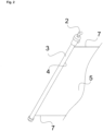
- Fig.1 shows a side view of a heat transfer element 1 according to the invention with a distributor 2 and a collector 3, which are arranged on a front side 4 of the flexible mat 5.
- the flexible mat 5 has a width 6 and two long sides 7.
- a closed connecting element 9 is arranged, which in Fig.6 shown flow channels 12.
- the heat transfer medium flows into the distributor 2 and is distributed by it to the Fig.6
- the heat transfer medium is distributed in the flow channels 12 shown, the direction of flow being indicated by the arrow 10.
- the heat transfer medium enters the closed connecting element 9, which transfers the heat transfer medium to the Fig.6 shown flow channels 12 through which the heat transfer medium flows in the direction indicated by the arrow 11.
- the heat transfer medium thus flows into the collector 3 and is led out of the heat transfer element.
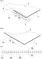
- Fig.2 and Fig.3 show a perspective view and a side view of a section of the heat transfer element according to the invention, according to Fig.1 .
- Fig.4 shows a sectional view of a section of the heat transfer element 1 according to the invention, according to Fig.1 .
- the distributor 2 and the collector 3 are designed as one component in an axially interlocking construction.
- the heat transfer medium flows into the distributor 2 and from there into the Fig.6 shown flow channels 12, which are arranged within the upper part of the flexible mat 5.
- the flow direction of the heat medium is marked with the arrow 10.
- the return of the heat transfer medium takes place via the Fig.1 connecting element 9 shown, which transfers the heat transfer medium to the Fig.6 shown flow channels 12, which are arranged within the lower part of the flexible mat 5, in the direction indicated by the arrow 11.
- the heat transfer medium then flows into the collector 3, from where it is led out of the heat transfer element 1.
- Fig.5 shows a perspective sectional view of a section of a heat transfer element 1 according to the invention.
- the connection between the distributor 2 and the flexible mat 5 or the flow channels 12 running therein is shown.
- the heat transfer medium flows into the distributor 2 and from here into the flow channels 12.
- the return of the heat transfer medium takes place via an analogous connection of the collector 3 ( Fig.4 ) or the connecting element 9 ( Fig.1 ).
- all flow channels 12 run parallel to the long side 7 of the flexible mat 5.
- the flow channels 12 have an inner wall 13, which is in contact with the heat transfer medium, and an outer wall 14.
- the outer wall 14 of the flow channels 12 forms the surface of the flexible mat 5, which is in contact with the environment.
- the flexible mat 5 is preferably made in one piece and preferably from plastic, for example by extrusion, with the wall thickness of the inner wall 10 and the outer wall 11 being thin, so that improved heat transfer and passage to the environment is achieved, whereby the residual heat, for example from the ground, can be used optimally.
- Fig.6 shows a perspective view of a section of a flexible mat 5 of a heat transfer element 1 according to the invention, according to Fig.5 .
- Fig.7 shows a sectional view of a flexible mat 5 of a heat transfer element 1 according to the invention, according to Fig.5
- the cross-section of the flow channels 12 is formed by two parallel walls 15 and two curved walls 16, so that the cross-section takes on a rectangle rounded on two sides.
- the shape of the cross-section can be adjusted by varying the respective walls. It is also conceivable that the flow channels 12 are not only next to each other, but also above each other, distributed chaotically and/or arranged in another way.
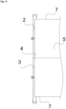
- Fig.8 shows a side view of a further embodiment of a heat transfer element 1 not according to the invention.
- the distributor 2 and the collector 3 are arranged axially aligned with each other.
- the advantage of this arrangement is that heat transfer according to the countercurrent principle between the distributor 2 and the collector 3 is avoided.
- Fig. 9 to Fig. 11 show a perspective view, a side view and a sectional view of a section of the heat transfer element 1 not according to the invention, according to Fig.8 .
- Fig. 12 to Fig. 15 show a side view, a perspective view of a detail, a side view of a detail and a sectional view of a detail of a further embodiment of a heat transfer element 1 not according to the invention, in which the two longitudinal axes of the distributor 2 and the collector 3 do not form a common longitudinal axis.
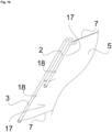
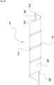
- Fig. 16 and Fig. 17 show a perspective view and a side view of a section of another embodiment of a heat transfer element 1.
- the flexible mat 5 is partially divided into two elements 17, so that the distributor 2 is arranged on the front side 18 of one element 14 and the collector 3 is arranged on the front side 18 of the second element 14.
- the front sides 18 of the two elements 14 form the front side 4 of the flexible mat.
- the flow direction of the heat transfer medium within an element 17 is the same.
- the undesirable heat transfer between the elements 17 can be minimized.
- Fig. 18 shows a perspective view of a further embodiment of a heat transfer element 1 not according to the invention.
- three flexible mats 5 are arranged on the distributor 2 or collector 3. By keeping the individual mats as far apart as possible from each other, the heat transfer between the flexible mats 5 is minimized and thus the efficiency of the heat transfer element 1 is increased.
- the flexible mats 5 can also be curved, for example, so that different arrangements are conceivable, which are determined, for example, by the space available.
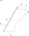
- Fig. 19 shows a side view of another embodiment of a heat transfer element 1 not according to the invention.
- the flexible mat 5 is designed in a helical arrangement. In this way, the area required for installation is reduced. This arrangement ensures that the temperature gradient between the surface of the flexible mat and the environment is increased, which increases the efficiency of the heat transfer element 1. Furthermore, for this arrangement it is necessary to change the angle between the distributor 2 or the collector 3 and the long side 7 of the flexible mat 5 in such a way that no tension occurs in the heat transfer element 1 due to the windings.
- Fig. 20 shows a side view of another embodiment of a heat transfer element 1 not according to the invention.
- Fig. 19 In contrast to the Fig. 19
- horizontal installation of the heat transfer element is also possible.
Landscapes
- Engineering & Computer Science (AREA)
- Mechanical Engineering (AREA)
- General Engineering & Computer Science (AREA)
- Physics & Mathematics (AREA)
- Thermal Sciences (AREA)
- Life Sciences & Earth Sciences (AREA)
- Sustainable Development (AREA)
- Sustainable Energy (AREA)
- Chemical & Material Sciences (AREA)
- Combustion & Propulsion (AREA)
- Heat-Exchange Devices With Radiators And Conduit Assemblies (AREA)
Claims (13)
- Élément de transfert de chaleur (1) pourvu d'au moins une natte flexible (5) sur laquelle sont disposés au moins un répartiteur (2) et au moins un collecteur (3), la natte flexible (5) présentant plusieurs canaux d'écoulement (12), au moins une face frontale, au moins une face longitudinale (7) et au moins une largeur (6), au moins un répartiteur (2) et au moins un collecteur (3) étant disposés sur la même face frontale (4) de la natte flexible (5), au moins un répartiteur (2) et au moins un collecteur (3) étant disposés au moins en partie axialement l'un dans l'autre,
caractérisé en ce que
tous les canaux d'écoulement (12) s'étendent parallèlement à l'axe longitudinal (7) de la natte flexible (5), que tous les canaux d'écoulement (12) parallèles de la natte flexible (5) débouchent dans au moins un répartiteur (2) et/ou au moins un collecteur (3) et que le répartiteur (2) est disposé dans le collecteur (3) de telle sorte que le répartiteur (2) peut être entouré au moins en partie par un fluide en écoulement dans le collecteur (3). - Élément de transfert de chaleur (1) selon la revendication 1,
caractérisé en ce que
au moins un répartiteur (2) et au moins un collecteur (3) sont disposés l'un par rapport à l'autre au moins en partie selon un alignement axial et/ou sont disposés au moins en partie parallèlement l'un à l'autre. - Élément de transfert de chaleur (1) selon la revendication 1 ou selon la revendication 2,
caractérisé en ce que
la natte flexible (5) présente au moins deux faces frontales (4, 8), au moins une face frontale (4) présentant par rapport à au moins une autre face frontale (8) un décalage en direction de la largeur (6) de la natte flexible (5) de l'élément de transfert de chaleur (1). - Élément de transfert de chaleur (1) selon l'une quelconque des revendications précédentes,
caractérisé en ce que
la natte flexible (5) est séparée au moins en partie en au moins deux éléments (17), les faces frontales (18) des éléments (17) obtenues grâce à la séparation formant ainsi la face frontale (4) de la natte flexible (5) sur laquelle sont disposés au moins un collecteur (3) et au moins un répartiteur (2). - Élément de transfert de chaleur (1) selon l'une quelconque des revendications précédentes,
caractérisé en ce que
au moins un répartiteur (2) et au moins un collecteur (3), au moins deux répartiteurs (2) et/ou au moins deux collecteurs (3) sont réalisés en une seule pièce. - Élément de transfert de chaleur (1) selon l'une quelconque des revendications précédentes,
caractérisé en ce que
au moins un dispositif de retenue est disposé sur au moins un répartiteur (2) et/ou sur au moins un collecteur (3). - Élément de transfert de chaleur (1) selon l'une quelconque des revendications précédentes,
caractérisé en ce que
ledit élément de transfert de chaleur (1) est constitué au moins en partie en un matériau résistant à la pression. - Élément de transfert de chaleur (1) selon l'une quelconque des revendications précédentes,
caractérisé en ce que
au moins un répartiteur (2) et/ou au moins un collecteur (3) est/sont réalisé(s) au moins en partie en un matériau flexible. - Élément de transfert de chaleur (1) selon l'une quelconque des revendications précédentes,
caractérisé en ce que
ledit élément de transfert de chaleur (1) est au moins en partie en matière plastique. - Élément de transfert de chaleur (1) selon l'une quelconque des revendications précédentes,
caractérisé en ce que
la natte flexible (5) est au moins en partie en matière plastique. - Élément de transfert de chaleur (1) selon l'une quelconque des revendications précédentes,
caractérisé en ce que
la natte flexible (5) est constituée de tubes disposés les uns à côté des autres. - Élément de transfert de chaleur (1) selon l'une quelconque des revendications précédentes,
caractérisé en ce que
au moins un canal d'écoulement (12) de la natte flexible (5) est un capillaire. - Élément de transfert de chaleur (1) selon l'une quelconque des revendications précédentes,
caractérisé en ce queau moins une face longitudinale (7) est disposée sur un répartiteur (2) selon un angle aigu, selon un angle droit et/ou selon un angle obtus et/ouau moins une face longitudinale (7) est disposée sur un collecteur (3) selon un angle aigu, selon un angle droit et/ou selon un angle obtus.
Priority Applications (1)
| Application Number | Priority Date | Filing Date | Title |
|---|---|---|---|
| EP18020565.0A EP3470743B1 (fr) | 2015-08-10 | 2016-08-10 | Élement de transfert thermique |
Applications Claiming Priority (1)
| Application Number | Priority Date | Filing Date | Title |
|---|---|---|---|
| DE102015010394.6A DE102015010394B4 (de) | 2015-08-10 | 2015-08-10 | Wärmeübertragungselement |
Related Child Applications (2)
| Application Number | Title | Priority Date | Filing Date |
|---|---|---|---|
| EP18020565.0A Division EP3470743B1 (fr) | 2015-08-10 | 2016-08-10 | Élement de transfert thermique |
| EP18020565.0A Division-Into EP3470743B1 (fr) | 2015-08-10 | 2016-08-10 | Élement de transfert thermique |
Publications (4)
| Publication Number | Publication Date |
|---|---|
| EP3130859A2 EP3130859A2 (fr) | 2017-02-15 |
| EP3130859A3 EP3130859A3 (fr) | 2017-03-08 |
| EP3130859C0 EP3130859C0 (fr) | 2024-07-24 |
| EP3130859B1 true EP3130859B1 (fr) | 2024-07-24 |
Family
ID=56883748
Family Applications (2)
| Application Number | Title | Priority Date | Filing Date |
|---|---|---|---|
| EP18020565.0A Active EP3470743B1 (fr) | 2015-08-10 | 2016-08-10 | Élement de transfert thermique |
| EP16400036.6A Active EP3130859B1 (fr) | 2015-08-10 | 2016-08-10 | Élement de transfert thermique |
Family Applications Before (1)
| Application Number | Title | Priority Date | Filing Date |
|---|---|---|---|
| EP18020565.0A Active EP3470743B1 (fr) | 2015-08-10 | 2016-08-10 | Élement de transfert thermique |
Country Status (2)
| Country | Link |
|---|---|
| EP (2) | EP3470743B1 (fr) |
| DE (1) | DE102015010394B4 (fr) |
Families Citing this family (2)
| Publication number | Priority date | Publication date | Assignee | Title |
|---|---|---|---|---|
| DE102017208816B3 (de) * | 2017-05-24 | 2018-11-15 | Thyssenkrupp Ag | Wärmeübertragungselement, Temperiervorrichtung und Batteriegehäuse mit mindestens einem Wärmeübertragungselement |
| FR3083592B1 (fr) * | 2018-07-06 | 2020-10-02 | Commissariat Energie Atomique | Dispositif de recuperation d'energie entre fluides gazeux, et procede de fabrication d'un tel dispositif |
Citations (1)
| Publication number | Priority date | Publication date | Assignee | Title |
|---|---|---|---|---|
| EP2985546A2 (fr) * | 2014-08-13 | 2016-02-17 | Mefa Befestigungs- und Montagesysteme GmbH | Élement de transfert thermique, agencement d'un element de transfert thermique destine a fabriquer un accumulateur d'energie |
Family Cites Families (13)
| Publication number | Priority date | Publication date | Assignee | Title |
|---|---|---|---|---|
| US3751935A (en) * | 1971-12-02 | 1973-08-14 | Calmac Manuf Corp | Method and system for creating and maintaining an ice slab |
| DE3101039A1 (de) | 1981-01-15 | 1982-08-05 | Hoechst Ag, 6000 Frankfurt | "waermespeicher und-austauscher" |
| DE3110719C2 (de) * | 1981-03-19 | 1983-02-17 | Helmut 7293 Pfalzgrafenweiler Genkinger | Wärmetauscher mit mehreren, in einem Gehäuse untergebrachten, spiralförmigen Verteilerrohrabschnitten |
| JPS5954011U (ja) * | 1982-10-02 | 1984-04-09 | ソ−ラ−技研工業株式会社 | 床暖房における向対流用ヘツダ−管 |
| DE3418561A1 (de) | 1984-05-16 | 1985-11-21 | Heinz-Günter 3134 Bergen Menz | Waermetauscher aus polymeren |
| US5445216A (en) * | 1994-03-10 | 1995-08-29 | Cannata; Antonio | Heat exchanger |
| IL109269A (en) * | 1994-04-10 | 1996-10-31 | Magen Plastic | Heat exchanger |
| DE4434386A1 (de) * | 1994-09-16 | 1996-03-21 | Albrecht Bauke | Ausbildung von Sammelrohren an einer Kunststoffrohrmatte für das Heizen und Kühlen von Gebäuden und zum Einsetzen in Wärmetauschern |
| DE19720863C5 (de) * | 1996-06-18 | 2006-08-03 | BeKa-Heiz- und Kühlmatten GmbH | Heiz- und/oder Kühlelement für Wände, Decken und/oder Fußböden von Gebäuden |
| EP0916061A1 (fr) * | 1996-08-05 | 1999-05-19 | Sandler Energietechnik GmbH & Co. KG | Panneau de chauffage ou de refroidissement a tubes capillaires pourvu d'une mince couche de couverture en ciment |
| AT7427U1 (de) * | 2004-01-19 | 2005-03-25 | Ast Eis Und Solartechnik Gmbh | Einrichtung zur strömungsverbindung von zueinander parallelen strömungskanälen einer wärmetauschmatte |
| FR2960946B1 (fr) * | 2010-06-03 | 2012-07-06 | Thierry Ledain | Dispositif destine aux echanges thermiques dans une installation de geothermie |
| EP2738504A1 (fr) * | 2012-11-30 | 2014-06-04 | Carlos Quesada Saborio | Élément de tubage pour supports d'échangeur de chaleur |
-
2015
- 2015-08-10 DE DE102015010394.6A patent/DE102015010394B4/de active Active
-
2016
- 2016-08-10 EP EP18020565.0A patent/EP3470743B1/fr active Active
- 2016-08-10 EP EP16400036.6A patent/EP3130859B1/fr active Active
Patent Citations (1)
| Publication number | Priority date | Publication date | Assignee | Title |
|---|---|---|---|---|
| EP2985546A2 (fr) * | 2014-08-13 | 2016-02-17 | Mefa Befestigungs- und Montagesysteme GmbH | Élement de transfert thermique, agencement d'un element de transfert thermique destine a fabriquer un accumulateur d'energie |
Also Published As
| Publication number | Publication date |
|---|---|
| EP3470743A1 (fr) | 2019-04-17 |
| EP3470743C0 (fr) | 2023-07-19 |
| EP3470743B1 (fr) | 2023-07-19 |
| DE102015010394B4 (de) | 2020-03-12 |
| EP3130859A3 (fr) | 2017-03-08 |
| DE102015010394A1 (de) | 2017-02-16 |
| EP3130859A2 (fr) | 2017-02-15 |
| EP3130859C0 (fr) | 2024-07-24 |
Similar Documents
| Publication | Publication Date | Title |
|---|---|---|
| DE19501547A1 (de) | Modularer Wärmeaustauscher | |
| DE102017119465B4 (de) | Trägervorrichtung für die Aufnahme von Batteriezellen einer Batterievorrichtung eines Fahrzeugs, Batteriemodul für eine Batterievorrichtung eines Fahrzeugs und Verfahren für die Anpassung einer Trägervorrichtung | |
| DE102013219388A1 (de) | Kühlungsvorrichtung | |
| DE202014002795U1 (de) | Flüssigkeitsabscheidevorrichtung | |
| EP2220451B1 (fr) | Élément répartiteur de fluide pour un dispositif de conduite de fluide, en particulier pour des appareils de conduite de fluide multicanaux imbriqués | |
| EP2886963B1 (fr) | Unité collectrice et de répartition pour le caloporteur d'une installation de chauffage dotée de plusieurs chaudières et plusieurs circuits de chauffe | |
| EP2636958B1 (fr) | Répartiteur de circuit de chauffage avec vase de découplage hydraulique intégré | |
| EP3470743B1 (fr) | Élement de transfert thermique | |
| DE102017219433B4 (de) | Wärmeübertrager für einen Verbrennungsmotor | |
| DE2604782B2 (de) | Plattenförmige Heiz- und/oder Kühleinheit zum Einbau in Decken, Fußböden und Wänden | |
| EP3156740B1 (fr) | Accumulateur d'énergie | |
| DE102018113339A1 (de) | Batteriekühlvorrichtung zur Kühlung einer Batterie, insbesondere der Batterie eines Kraftfahrzeugs bzw. Anordnungsstruktur mit mindestens einer Batterie, insbesondere einer Batterie eines Kraftfahrzeugs und mit der zuvor genannten Batteriekühlvorrichtung | |
| DE3241536A1 (de) | Anschlussvorrichtung fuer heizungsanlagen | |
| DE112015003901B4 (de) | Sammelkammer für einen Wärmetauscher, Verbindungssystem und Wärmetauscher | |
| EP3239641A1 (fr) | Tube plat pour un caloporteur | |
| DE102012011926A1 (de) | Wärmetauscherregister | |
| EP2206971A2 (fr) | Accumulateur thermique | |
| DE102013010678A1 (de) | Kühlbrückenelement zur Umlenkung von Temperierflüssigkeiten an Spritzguss- und Druckgusswerkzeugen | |
| DE102005048838A1 (de) | Wärmetauscher | |
| DE1540502C3 (de) | Schienenkanal für gekapselte elektrische Verteilungen | |
| DE102017130090A1 (de) | Vorrichtung sowie Verfahren zum Temperieren eines Raumes | |
| DE6606627U (de) | Energiefuehrungskette | |
| EP3155268B1 (fr) | Dispositif de raccordement | |
| EP3418640B1 (fr) | Distributeur pour un échangeur de chaleur à plaques | |
| DE102023126798A1 (de) | Vorrichtung zum Temperieren eines Batteriesystems |
Legal Events
| Date | Code | Title | Description |
|---|---|---|---|
| PUAI | Public reference made under article 153(3) epc to a published international application that has entered the european phase |
Free format text: ORIGINAL CODE: 0009012 |
|
| STAA | Information on the status of an ep patent application or granted ep patent |
Free format text: STATUS: THE APPLICATION HAS BEEN PUBLISHED |
|
| PUAL | Search report despatched |
Free format text: ORIGINAL CODE: 0009013 |
|
| AK | Designated contracting states |
Kind code of ref document: A2 Designated state(s): AL AT BE BG CH CY CZ DE DK EE ES FI FR GB GR HR HU IE IS IT LI LT LU LV MC MK MT NL NO PL PT RO RS SE SI SK SM TR |
|
| AX | Request for extension of the european patent |
Extension state: BA ME |
|
| AK | Designated contracting states |
Kind code of ref document: A3 Designated state(s): AL AT BE BG CH CY CZ DE DK EE ES FI FR GB GR HR HU IE IS IT LI LT LU LV MC MK MT NL NO PL PT RO RS SE SI SK SM TR |
|
| AX | Request for extension of the european patent |
Extension state: BA ME |
|
| RIC1 | Information provided on ipc code assigned before grant |
Ipc: F24D 3/14 20060101AFI20170202BHEP |
|
| STAA | Information on the status of an ep patent application or granted ep patent |
Free format text: STATUS: REQUEST FOR EXAMINATION WAS MADE |
|
| 17P | Request for examination filed |
Effective date: 20170530 |
|
| RBV | Designated contracting states (corrected) |
Designated state(s): AL AT BE BG CH CY CZ DE DK EE ES FI FR GB GR HR HU IE IS IT LI LT LU LV MC MK MT NL NO PL PT RO RS SE SI SK SM TR |
|
| STAA | Information on the status of an ep patent application or granted ep patent |
Free format text: STATUS: EXAMINATION IS IN PROGRESS |
|
| 17Q | First examination report despatched |
Effective date: 20180817 |
|
| GRAP | Despatch of communication of intention to grant a patent |
Free format text: ORIGINAL CODE: EPIDOSNIGR1 |
|
| STAA | Information on the status of an ep patent application or granted ep patent |
Free format text: STATUS: GRANT OF PATENT IS INTENDED |
|
| GRAS | Grant fee paid |
Free format text: ORIGINAL CODE: EPIDOSNIGR3 |
|
| INTG | Intention to grant announced |
Effective date: 20240502 |
|
| GRAA | (expected) grant |
Free format text: ORIGINAL CODE: 0009210 |
|
| STAA | Information on the status of an ep patent application or granted ep patent |
Free format text: STATUS: THE PATENT HAS BEEN GRANTED |
|
| AK | Designated contracting states |
Kind code of ref document: B1 Designated state(s): AL AT BE BG CH CY CZ DE DK EE ES FI FR GB GR HR HU IE IS IT LI LT LU LV MC MK MT NL NO PL PT RO RS SE SI SK SM TR |
|
| REG | Reference to a national code |
Ref country code: GB Ref legal event code: FG4D Free format text: NOT ENGLISH |
|
| REG | Reference to a national code |
Ref country code: CH Ref legal event code: EP |
|
| REG | Reference to a national code |
Ref country code: IE Ref legal event code: FG4D Free format text: LANGUAGE OF EP DOCUMENT: GERMAN Ref country code: DE Ref legal event code: R096 Ref document number: 502016016642 Country of ref document: DE |
|
| U01 | Request for unitary effect filed |
Effective date: 20240807 |
|
| U07 | Unitary effect registered |
Designated state(s): AT BE BG DE DK EE FI FR IT LT LU LV MT NL PT SE SI Effective date: 20240823 |
|
| U20 | Renewal fee for the european patent with unitary effect paid |
Year of fee payment: 9 Effective date: 20240820 |
|
| PG25 | Lapsed in a contracting state [announced via postgrant information from national office to epo] |
Ref country code: NO Free format text: LAPSE BECAUSE OF FAILURE TO SUBMIT A TRANSLATION OF THE DESCRIPTION OR TO PAY THE FEE WITHIN THE PRESCRIBED TIME-LIMIT Effective date: 20241024 |
|
| PG25 | Lapsed in a contracting state [announced via postgrant information from national office to epo] |
Ref country code: PL Free format text: LAPSE BECAUSE OF FAILURE TO SUBMIT A TRANSLATION OF THE DESCRIPTION OR TO PAY THE FEE WITHIN THE PRESCRIBED TIME-LIMIT Effective date: 20240724 Ref country code: GR Free format text: LAPSE BECAUSE OF FAILURE TO SUBMIT A TRANSLATION OF THE DESCRIPTION OR TO PAY THE FEE WITHIN THE PRESCRIBED TIME-LIMIT Effective date: 20241025 |
|
| PG25 | Lapsed in a contracting state [announced via postgrant information from national office to epo] |
Ref country code: IS Free format text: LAPSE BECAUSE OF FAILURE TO SUBMIT A TRANSLATION OF THE DESCRIPTION OR TO PAY THE FEE WITHIN THE PRESCRIBED TIME-LIMIT Effective date: 20241124 |
|
| PG25 | Lapsed in a contracting state [announced via postgrant information from national office to epo] |
Ref country code: HR Free format text: LAPSE BECAUSE OF FAILURE TO SUBMIT A TRANSLATION OF THE DESCRIPTION OR TO PAY THE FEE WITHIN THE PRESCRIBED TIME-LIMIT Effective date: 20240724 |
|
| PG25 | Lapsed in a contracting state [announced via postgrant information from national office to epo] |
Ref country code: RS Free format text: LAPSE BECAUSE OF FAILURE TO SUBMIT A TRANSLATION OF THE DESCRIPTION OR TO PAY THE FEE WITHIN THE PRESCRIBED TIME-LIMIT Effective date: 20241024 Ref country code: ES Free format text: LAPSE BECAUSE OF FAILURE TO SUBMIT A TRANSLATION OF THE DESCRIPTION OR TO PAY THE FEE WITHIN THE PRESCRIBED TIME-LIMIT Effective date: 20240724 |
|
| PG25 | Lapsed in a contracting state [announced via postgrant information from national office to epo] |
Ref country code: RS Free format text: LAPSE BECAUSE OF FAILURE TO SUBMIT A TRANSLATION OF THE DESCRIPTION OR TO PAY THE FEE WITHIN THE PRESCRIBED TIME-LIMIT Effective date: 20241024 Ref country code: PL Free format text: LAPSE BECAUSE OF FAILURE TO SUBMIT A TRANSLATION OF THE DESCRIPTION OR TO PAY THE FEE WITHIN THE PRESCRIBED TIME-LIMIT Effective date: 20240724 Ref country code: NO Free format text: LAPSE BECAUSE OF FAILURE TO SUBMIT A TRANSLATION OF THE DESCRIPTION OR TO PAY THE FEE WITHIN THE PRESCRIBED TIME-LIMIT Effective date: 20241024 Ref country code: IS Free format text: LAPSE BECAUSE OF FAILURE TO SUBMIT A TRANSLATION OF THE DESCRIPTION OR TO PAY THE FEE WITHIN THE PRESCRIBED TIME-LIMIT Effective date: 20241124 Ref country code: HR Free format text: LAPSE BECAUSE OF FAILURE TO SUBMIT A TRANSLATION OF THE DESCRIPTION OR TO PAY THE FEE WITHIN THE PRESCRIBED TIME-LIMIT Effective date: 20240724 Ref country code: GR Free format text: LAPSE BECAUSE OF FAILURE TO SUBMIT A TRANSLATION OF THE DESCRIPTION OR TO PAY THE FEE WITHIN THE PRESCRIBED TIME-LIMIT Effective date: 20241025 Ref country code: ES Free format text: LAPSE BECAUSE OF FAILURE TO SUBMIT A TRANSLATION OF THE DESCRIPTION OR TO PAY THE FEE WITHIN THE PRESCRIBED TIME-LIMIT Effective date: 20240724 |
|
| REG | Reference to a national code |
Ref country code: CH Ref legal event code: PL |
|
| PG25 | Lapsed in a contracting state [announced via postgrant information from national office to epo] |
Ref country code: SM Free format text: LAPSE BECAUSE OF FAILURE TO SUBMIT A TRANSLATION OF THE DESCRIPTION OR TO PAY THE FEE WITHIN THE PRESCRIBED TIME-LIMIT Effective date: 20240724 Ref country code: RO Free format text: LAPSE BECAUSE OF FAILURE TO SUBMIT A TRANSLATION OF THE DESCRIPTION OR TO PAY THE FEE WITHIN THE PRESCRIBED TIME-LIMIT Effective date: 20240724 |
|
| PG25 | Lapsed in a contracting state [announced via postgrant information from national office to epo] |
Ref country code: CH Free format text: LAPSE BECAUSE OF NON-PAYMENT OF DUE FEES Effective date: 20240831 Ref country code: MC Free format text: LAPSE BECAUSE OF FAILURE TO SUBMIT A TRANSLATION OF THE DESCRIPTION OR TO PAY THE FEE WITHIN THE PRESCRIBED TIME-LIMIT Effective date: 20240724 |
|
| PG25 | Lapsed in a contracting state [announced via postgrant information from national office to epo] |
Ref country code: CZ Free format text: LAPSE BECAUSE OF FAILURE TO SUBMIT A TRANSLATION OF THE DESCRIPTION OR TO PAY THE FEE WITHIN THE PRESCRIBED TIME-LIMIT Effective date: 20240724 |
|
| PG25 | Lapsed in a contracting state [announced via postgrant information from national office to epo] |
Ref country code: SK Free format text: LAPSE BECAUSE OF FAILURE TO SUBMIT A TRANSLATION OF THE DESCRIPTION OR TO PAY THE FEE WITHIN THE PRESCRIBED TIME-LIMIT Effective date: 20240724 |
|
| PLBE | No opposition filed within time limit |
Free format text: ORIGINAL CODE: 0009261 |
|
| STAA | Information on the status of an ep patent application or granted ep patent |
Free format text: STATUS: NO OPPOSITION FILED WITHIN TIME LIMIT |
|
| GBPC | Gb: european patent ceased through non-payment of renewal fee |
Effective date: 20241024 |
|
| 26N | No opposition filed |
Effective date: 20250425 |
|
| PG25 | Lapsed in a contracting state [announced via postgrant information from national office to epo] |
Ref country code: GB Free format text: LAPSE BECAUSE OF NON-PAYMENT OF DUE FEES Effective date: 20241024 |
|
| PG25 | Lapsed in a contracting state [announced via postgrant information from national office to epo] |
Ref country code: IE Free format text: LAPSE BECAUSE OF NON-PAYMENT OF DUE FEES Effective date: 20240810 |
|
| U20 | Renewal fee for the european patent with unitary effect paid |
Year of fee payment: 10 Effective date: 20250801 |
|
| PG25 | Lapsed in a contracting state [announced via postgrant information from national office to epo] |
Ref country code: CY Free format text: LAPSE BECAUSE OF FAILURE TO SUBMIT A TRANSLATION OF THE DESCRIPTION OR TO PAY THE FEE WITHIN THE PRESCRIBED TIME-LIMIT; INVALID AB INITIO Effective date: 20160810 |
|
| PG25 | Lapsed in a contracting state [announced via postgrant information from national office to epo] |
Ref country code: HU Free format text: LAPSE BECAUSE OF FAILURE TO SUBMIT A TRANSLATION OF THE DESCRIPTION OR TO PAY THE FEE WITHIN THE PRESCRIBED TIME-LIMIT; INVALID AB INITIO Effective date: 20160810 |