EP3155268B1 - Dispositif de raccordement - Google Patents
Dispositif de raccordement Download PDFInfo
- Publication number
- EP3155268B1 EP3155268B1 EP15727878.9A EP15727878A EP3155268B1 EP 3155268 B1 EP3155268 B1 EP 3155268B1 EP 15727878 A EP15727878 A EP 15727878A EP 3155268 B1 EP3155268 B1 EP 3155268B1
- Authority
- EP
- European Patent Office
- Prior art keywords
- fluid passage
- functional component
- fluid
- component
- basic
- Prior art date
- Legal status (The legal status is an assumption and is not a legal conclusion. Google has not performed a legal analysis and makes no representation as to the accuracy of the status listed.)
- Active
Links
Images

Classifications
-
- F—MECHANICAL ENGINEERING; LIGHTING; HEATING; WEAPONS; BLASTING
- F15—FLUID-PRESSURE ACTUATORS; HYDRAULICS OR PNEUMATICS IN GENERAL
- F15B—SYSTEMS ACTING BY MEANS OF FLUIDS IN GENERAL; FLUID-PRESSURE ACTUATORS, e.g. SERVOMOTORS; DETAILS OF FLUID-PRESSURE SYSTEMS, NOT OTHERWISE PROVIDED FOR
- F15B13/00—Details of servomotor systems ; Valves for servomotor systems
- F15B13/02—Fluid distribution or supply devices characterised by their adaptation to the control of servomotors
-
- F—MECHANICAL ENGINEERING; LIGHTING; HEATING; WEAPONS; BLASTING
- F15—FLUID-PRESSURE ACTUATORS; HYDRAULICS OR PNEUMATICS IN GENERAL
- F15B—SYSTEMS ACTING BY MEANS OF FLUIDS IN GENERAL; FLUID-PRESSURE ACTUATORS, e.g. SERVOMOTORS; DETAILS OF FLUID-PRESSURE SYSTEMS, NOT OTHERWISE PROVIDED FOR
- F15B13/00—Details of servomotor systems ; Valves for servomotor systems
- F15B13/02—Fluid distribution or supply devices characterised by their adaptation to the control of servomotors
- F15B13/06—Fluid distribution or supply devices characterised by their adaptation to the control of servomotors for use with two or more servomotors
- F15B13/08—Assemblies of units, each for the control of a single servomotor only
- F15B13/0803—Modular units
- F15B13/0871—Channels for fluid
-
- F—MECHANICAL ENGINEERING; LIGHTING; HEATING; WEAPONS; BLASTING
- F15—FLUID-PRESSURE ACTUATORS; HYDRAULICS OR PNEUMATICS IN GENERAL
- F15B—SYSTEMS ACTING BY MEANS OF FLUIDS IN GENERAL; FLUID-PRESSURE ACTUATORS, e.g. SERVOMOTORS; DETAILS OF FLUID-PRESSURE SYSTEMS, NOT OTHERWISE PROVIDED FOR
- F15B13/00—Details of servomotor systems ; Valves for servomotor systems
- F15B13/02—Fluid distribution or supply devices characterised by their adaptation to the control of servomotors
- F15B13/06—Fluid distribution or supply devices characterised by their adaptation to the control of servomotors for use with two or more servomotors
- F15B13/08—Assemblies of units, each for the control of a single servomotor only
-
- F—MECHANICAL ENGINEERING; LIGHTING; HEATING; WEAPONS; BLASTING
- F15—FLUID-PRESSURE ACTUATORS; HYDRAULICS OR PNEUMATICS IN GENERAL
- F15B—SYSTEMS ACTING BY MEANS OF FLUIDS IN GENERAL; FLUID-PRESSURE ACTUATORS, e.g. SERVOMOTORS; DETAILS OF FLUID-PRESSURE SYSTEMS, NOT OTHERWISE PROVIDED FOR
- F15B13/00—Details of servomotor systems ; Valves for servomotor systems
- F15B13/02—Fluid distribution or supply devices characterised by their adaptation to the control of servomotors
- F15B13/06—Fluid distribution or supply devices characterised by their adaptation to the control of servomotors for use with two or more servomotors
- F15B13/08—Assemblies of units, each for the control of a single servomotor only
- F15B13/0803—Modular units
- F15B13/0878—Assembly of modular units
-
- F—MECHANICAL ENGINEERING; LIGHTING; HEATING; WEAPONS; BLASTING
- F15—FLUID-PRESSURE ACTUATORS; HYDRAULICS OR PNEUMATICS IN GENERAL
- F15B—SYSTEMS ACTING BY MEANS OF FLUIDS IN GENERAL; FLUID-PRESSURE ACTUATORS, e.g. SERVOMOTORS; DETAILS OF FLUID-PRESSURE SYSTEMS, NOT OTHERWISE PROVIDED FOR
- F15B21/00—Common features of fluid actuator systems; Fluid-pressure actuator systems or details thereof, not covered by any other group of this subclass
- F15B21/003—Systems with different interchangeable components, e.g. using preassembled kits
-
- F—MECHANICAL ENGINEERING; LIGHTING; HEATING; WEAPONS; BLASTING
- F15—FLUID-PRESSURE ACTUATORS; HYDRAULICS OR PNEUMATICS IN GENERAL
- F15B—SYSTEMS ACTING BY MEANS OF FLUIDS IN GENERAL; FLUID-PRESSURE ACTUATORS, e.g. SERVOMOTORS; DETAILS OF FLUID-PRESSURE SYSTEMS, NOT OTHERWISE PROVIDED FOR
- F15B13/00—Details of servomotor systems ; Valves for servomotor systems
- F15B2013/002—Modular valves, i.e. consisting of an assembly of interchangeable components
-
- F—MECHANICAL ENGINEERING; LIGHTING; HEATING; WEAPONS; BLASTING
- F15—FLUID-PRESSURE ACTUATORS; HYDRAULICS OR PNEUMATICS IN GENERAL
- F15B—SYSTEMS ACTING BY MEANS OF FLUIDS IN GENERAL; FLUID-PRESSURE ACTUATORS, e.g. SERVOMOTORS; DETAILS OF FLUID-PRESSURE SYSTEMS, NOT OTHERWISE PROVIDED FOR
- F15B13/00—Details of servomotor systems ; Valves for servomotor systems
- F15B2013/002—Modular valves, i.e. consisting of an assembly of interchangeable components
- F15B2013/006—Modular components with multiple uses, e.g. kits for either normally-open or normally-closed valves, interchangeable or reprogrammable manifolds
Definitions
- the invention relates to a connection device.
- the individual line strands preferably produce a shortest connection between this central line and the further fluid passage point that can be assigned in each case, and preferably run in a direction perpendicular to the central line.
- the blocking parts preferably in the form of so-called ball expanders, which can be inserted into the respective strands of the connecting lines that are not required formed, the connection line that is not required in the base body can be safely blocked with the functional component and, with regard to the established sealing connection, depending on the purposes for which the connection device according to the invention is to be used, additional sealing devices such as O-sealing rings, which are fundamentally prone to failure, are omitted on the part of the base body, which in turn helps reduce costs.
- additional sealing devices such as O-sealing rings, which are fundamentally prone to failure
- connection device solution according to the invention is particularly suitable for controlling channels and channel connections, preferably in the form of control lines, for example in the form of so-called LS lines in control blocks of mobile work equipment and machines that can be loaded with pressures of up to approx. 400 bar.
- the connecting strand arranged on the output side of the functional component as part of a connecting line can be provided as a direct tank connection to the basic component; However, it can also serve as a continuation control line in the high-pressure area, provided that several connection devices and their components are combined to form functional groups.
- Both the basic component and the basic body are preferably designed in the form of valve or flange blocks which can be connected to one another in a releasable manner, for example by means of a screw connection.
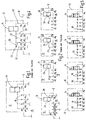
- the base body 12 according to the representation according to FIG Fig. 1 two further fluid passage points P 1 and P x , which can be connected to one another with the correspondingly assigned fluid passage points P ' 1 and P' x in the basic component 10 in a fluid-carrying manner via the functional component 14.
- There is also a locking part 16 (see also even Fig. 3 ), which blocks the respective fluid passage point P ' 2 , P' 3 , P ' n ... P' x-1 in the basic component 10, so that the relevant passage points remain unaffected by the functional component 14.
- Both the basic component 10 and the basic body 12 are designed in the manner of valve or flange blocks which can be connected to one another in a flange-like manner to form an overall system.
- the lower housing wall 18 of the flange-like base body 12 forms the blocking part 16, which in this respect covers the fluid passage points P ' 2 , P' 3 , P ' n ... P' x-1 in a blocking manner.
- Radial widenings 20 are provided at the relevant fluid passage points of the basic component 10, which allow the insertion of a sealant, preferably in the form of an O-sealing ring 22, the respective O-sealing ring 22 being inserted before the flange-like connection between the body 12 and the basic component 10 is made.
- the respective sealing means therefore ends in the form of the O-sealing ring 22 with at least part of its overhead outer contour on a flange side in the form of the lower housing wall 18 of the base body 12 in the area of the additional fluid passage points P ' 1 , P' 2 , P 'that can be assigned. 3 , P ' n ... P' x in the connected state of the base body 12 and the base component 10 and is in sealing contact with this wall 18.
- passage P x , P ' x another passage could be selected on the output side, such as a combination P x-1 / P' x-1 .
- a total of four different base bodies 12 would therefore be necessary to control four fluid passage points P ' 1 , P' 2 , P ' 3 and P' n on the inlet side, all of which are similar and in this respect also in FIG Fig. 2 are provided with the same reference numerals, but still differ in the design of the internal fluid-carrying piping and the connection geometry with regard to the further fluid passage points P 1 , P 2 , P 3 , P n ... P x .
- connection device solution according to the invention shown below, it being noted in advance for clarification that the respective fluid passage points mentioned are not as in FIGS Figures 1, 2, 4 and 5 shown in principle, characterize the respective block image in a linear arrangement one behind the other, but rather that these can be arranged in groups also randomly distributed, as can be seen from the Fig.
- a central line 30, preferably running horizontally, is now provided in the base body 12, which replaces the large number of previously differently arranged connecting lines in the flange-like base body 12.
- the functional component 14 is in turn connected into the central line 30; that was previously represented in the manner of a black box in the Fig. 5 is shown in the design of a 2/2-way switching valve, which can be controlled by means of an electromagnetic device, for example in the form of a proportional magnet and in the Fig. 5 is shown in the through-connected position.
- the blocking element solution presented is inherently self-sealing, so that the already described and customary O-sealing rings 22 can also be dispensed with, at least in the area of the blocking parts 16 used.
- the blocking part 16 is introduced at a different point, i.e. within a different connecting strand, this can be easily implemented by simply inserting the independent blocking part 16 as a repetitive component into the desired wiring harness 32 to be occupied.
- a step-like widening 42 can be provided in this, on which the blocking part 16 can then be supported with its bottom side for the spreading process described.
- the mentioned ball expander solution for realizing the respective locking part 16 fulfills all of the requirements set out above.
- the installation space required by the ball expander primarily only requires a small diameter step 42, as explained, and the sealing solution mentioned can also be subjected to high pressures physically from two sides without failure.
- the blocking part 16 in the form of the ball expander can be attached and installed quickly and in a process-stable manner in the assignable line strands 32. This is with the previous sealing solutions, as exemplified in the Fig. 3 are not possible.
Landscapes
- Engineering & Computer Science (AREA)
- Physics & Mathematics (AREA)
- Fluid Mechanics (AREA)
- Mechanical Engineering (AREA)
- General Engineering & Computer Science (AREA)
- Chemical & Material Sciences (AREA)
- Analytical Chemistry (AREA)
- Quick-Acting Or Multi-Walled Pipe Joints (AREA)
- Valve Housings (AREA)
Claims (5)
- Dispositif de raccordement comprenant- au moins une pièce (10) de base, qui dispose de plusieurs points (P'1, P'2, P'3, P'n...P'x) de passage de fluide voisins les uns des autres,- un corps (12) de base, qui sert par une pièce (14) de fonction sous la forme d'un dispositif de vanne à la commande d'un courant de fluide,dans lequel le corps (12) de base a plusieurs autres points (P1, P2, P3, Pn...Px) de passage de fluide, qui sont en communication fluidique avec les points (P'1, P'2, P'3, P'n...P'x) de passage de fluide pouvant être associés de la pièce (10) de base,dans lequel le corps (12) de base a au moins une partie (16) de blocage qui peut bloquer les points de passage de fluide respectif de la pièce (10) de base et/ou du corps (12) de base, qui reste non influencé par la pièce (14) de fonction, dans lequel à l'intérieur du corps (12) de base entre les autres points (P1, P2, P3, Pn...Px) de passage et la pièce (14) de fonction, est constituée respectivement une ligne (30, 32) de liaison fluidique, qui peut être bloquée par une partie (16) de blocage distincte dans la mesure où la liaison à la pièce (14) de fonction reste inutilisée, dans lequel les lignes de liaison respectives sont constituées d'une ligne (30) centrale, dans laquelle est montée la pièce (14) de fonction, et de divers brins (32) de ligne qui donnent une liaison entre cette ligne (30) centrale et les autres points (P1, P2, P3, Pn...Px) de passage de fluide pouvant être associés respectivement,dans lequel seulement un brin (32) de ligne fluidique conduit par la ligne (30) centrale au côté (34) d'entrée de la pièce (14) de fonction et à nouveau seulement un brin (32) de ligne fluidique est raccordé par la ligne (30) centrale au côté (26) de sortie de la pièce (14) de fonction, etdans lequel du côté (26) de sortie de la pièce (14) de fonction avant le brin (32) de ligne sortant en dernier du corps (12) de base, la pièce (14) de fonction est montée dans la ligne (30) centrale.
- Dispositif de raccordement suivant la revendication 1, caractérisé en ce que les lignes (30, 32) de liaison débouchent vers l'extérieur à partir du corps (12) de base par les autres points (P1, P2, P3, Pn...Px) de passage de fluide pouvant être associés respectivement et en ce que la partie (16) respective de blocage peut être insérée, de préférence en y restant, dans la ligne (32) de liaison de l'extérieur par les autres points (P1, P2, P3, Pn...Px) de passage de fluide.
- Dispositif de raccordement suivant la revendication 1 ou 2, caractérisé en ce que la partie (16) respectivement de blocage est formée d'un bouchon d'étanchéité, de préférence sous la forme d'un expanseur sphérique.
- Dispositif de raccordement suivant l'une des revendications précédentes, caractérisé en ce que le corps (12) de base est constitué à la manière d'un bloc de bride qui peut se brider à la pièce (10) de base pour donner un système d'ensemble.
- Dispositif de raccordement suivant l'une des revendications précédentes, caractérisé en ce que les divers brins (32) de ligne donnent une liaison la plus courte entre cette ligne (30) centrale et les autres points (P1, P2, P3, Pn...Px) de passage de fluide pouvant être associés respectivement et s'étendent de préférence dans une direction perpendiculaire à la ligne (30) centrale.
Applications Claiming Priority (2)
| Application Number | Priority Date | Filing Date | Title |
|---|---|---|---|
| DE102014008648.8A DE102014008648A1 (de) | 2014-06-13 | 2014-06-13 | Anschlussvorrichtung |
| PCT/EP2015/001118 WO2015188920A1 (fr) | 2014-06-13 | 2015-06-02 | Dispositif de raccordement |
Publications (2)
| Publication Number | Publication Date |
|---|---|
| EP3155268A1 EP3155268A1 (fr) | 2017-04-19 |
| EP3155268B1 true EP3155268B1 (fr) | 2021-09-29 |
Family
ID=53373387
Family Applications (1)
| Application Number | Title | Priority Date | Filing Date |
|---|---|---|---|
| EP15727878.9A Active EP3155268B1 (fr) | 2014-06-13 | 2015-06-02 | Dispositif de raccordement |
Country Status (5)
| Country | Link |
|---|---|
| US (1) | US10024343B2 (fr) |
| EP (1) | EP3155268B1 (fr) |
| CN (1) | CN206360957U (fr) |
| DE (1) | DE102014008648A1 (fr) |
| WO (1) | WO2015188920A1 (fr) |
Family Cites Families (11)
| Publication number | Priority date | Publication date | Assignee | Title |
|---|---|---|---|---|
| CH508828A (de) * | 1970-07-08 | 1971-06-15 | Hirmann Georg | Verfahren zum Verschliessen von Bohrungen in Werkstücken und Stopfen zur Ausführung des Verfahrens |
| GB1562039A (en) * | 1977-04-18 | 1980-03-05 | Kay F X | Fluid pressureoperated systems |
| AT367526B (de) * | 1980-10-20 | 1982-07-12 | Voest Alpine Ag | Ventilblock |
| DE3612684A1 (de) * | 1986-04-15 | 1987-10-22 | Heilmeier & Weinlein | Hydraulische steuervorrichtung |
| JP2521544B2 (ja) * | 1989-12-07 | 1996-08-07 | 株式会社コスメック | 油圧装置の圧力保障弁付き三方弁装置 |
| DE4204416A1 (de) * | 1991-04-19 | 1992-10-22 | Teves Gmbh Alfred | Hydraulische bremsanlage, insbesondere zur blockierschutzregelung |
| DE4120300A1 (de) * | 1991-06-17 | 1992-12-24 | Mannesmann Ag | Anschlussplatte mit stetigventil in modulbauweise, insbesondere fuer pneumatische medien |
| DE59908026D1 (de) | 1998-05-08 | 2004-01-22 | Festo Ag & Co | Mikroventilbatterie |
| DE20013360U1 (de) * | 2000-08-03 | 2001-09-13 | Fa. Hermann Heye i.K., 31683 Obernkirchen | Ventilblock für eine Glasformmaschine |
| JP2006084002A (ja) * | 2004-09-17 | 2006-03-30 | Ckd Corp | 流路ブロック |
| EP2472163B1 (fr) * | 2010-12-28 | 2013-08-21 | HAWE Hydraulik SE | Dispositif hydraulique |
-
2014
- 2014-06-13 DE DE102014008648.8A patent/DE102014008648A1/de not_active Withdrawn
-
2015
- 2015-06-02 US US15/318,389 patent/US10024343B2/en active Active
- 2015-06-02 WO PCT/EP2015/001118 patent/WO2015188920A1/fr not_active Ceased
- 2015-06-02 CN CN201590000726.3U patent/CN206360957U/zh not_active Expired - Lifetime
- 2015-06-02 EP EP15727878.9A patent/EP3155268B1/fr active Active
Also Published As
| Publication number | Publication date |
|---|---|
| CN206360957U (zh) | 2017-07-28 |
| WO2015188920A1 (fr) | 2015-12-17 |
| DE102014008648A1 (de) | 2015-12-17 |
| EP3155268A1 (fr) | 2017-04-19 |
| US10024343B2 (en) | 2018-07-17 |
| US20170122344A1 (en) | 2017-05-04 |
Similar Documents
| Publication | Publication Date | Title |
|---|---|---|
| DE10112496B4 (de) | Ventilblock für elektrohydraulische Steuereinrichtung und Mehrwegventile hierfür | |
| EP2350506B1 (fr) | Agencement de soupape hydraulique muni d'une soupape integree presentant un corps de fermeture a compensation de pression | |
| EP1629336B1 (fr) | Soupape | |
| EP2220380B1 (fr) | Vanne hydraulique | |
| EP3390177B1 (fr) | Unité soupape pour la modulation de pression dans un système de freinage à air comprimé | |
| DE102017206394A1 (de) | Druckhalteventilanordnung für einen Spülkreislauf eines geschlossenen hydraulischen Kreislaufs | |
| DE102006060334B4 (de) | Hydraulische Ventilanordnung | |
| DE2204219A1 (de) | Durchflußregelsystem | |
| DE2707134A1 (de) | Vorrichtung zur durchflussregelung | |
| EP3295065A1 (fr) | Soupape, en particulier soupape proportionnelle de régulation de pression | |
| DE102014009996A1 (de) | Ventil-Baukastensystem | |
| DE202009006313U1 (de) | Anordnung als Baukastensystem zur Steuerung von Differentialzylindern | |
| DE4416285A1 (de) | Elektropneumatische Ventileinrichtung | |
| EP3130859B1 (fr) | Élement de transfert thermique | |
| DE102013003248A1 (de) | Hydraulische Load-Sensing Steueranordnung | |
| EP3514418B1 (fr) | Cartouche de soupape pour un bloc de soupape | |
| WO2015188920A1 (fr) | Dispositif de raccordement | |
| DE102016212306A1 (de) | Zwischenblock und Kompaktachse mit einem Zwischenblock | |
| EP0612963A2 (fr) | Groupe distributeur pour des installations de chauffage et/ou réfrigération fonctionnant par un agent caloporteur étant capable de circuler | |
| DE102008009721A1 (de) | Ventilanordnung | |
| EP3149370A1 (fr) | Dispositif formant soupape, en particulier du type soupape anti-retour et procédé de fonctionnement d'un tel dispositif formant soupape | |
| EP1801426B1 (fr) | Agencement de couplage hydraulique ou pneumatique | |
| DE4409667C1 (de) | Wegeventilanordnung mit Wegeventil und Grundplatte | |
| EP1729014B1 (fr) | Bloc de commande et section de bloc de commande | |
| DE102015206224A1 (de) | Wälzlagerkäfig |
Legal Events
| Date | Code | Title | Description |
|---|---|---|---|
| STAA | Information on the status of an ep patent application or granted ep patent |
Free format text: STATUS: THE INTERNATIONAL PUBLICATION HAS BEEN MADE |
|
| PUAI | Public reference made under article 153(3) epc to a published international application that has entered the european phase |
Free format text: ORIGINAL CODE: 0009012 |
|
| STAA | Information on the status of an ep patent application or granted ep patent |
Free format text: STATUS: REQUEST FOR EXAMINATION WAS MADE |
|
| 17P | Request for examination filed |
Effective date: 20161128 |
|
| AK | Designated contracting states |
Kind code of ref document: A1 Designated state(s): AL AT BE BG CH CY CZ DE DK EE ES FI FR GB GR HR HU IE IS IT LI LT LU LV MC MK MT NL NO PL PT RO RS SE SI SK SM TR |
|
| AX | Request for extension of the european patent |
Extension state: BA ME |
|
| DAV | Request for validation of the european patent (deleted) | ||
| DAX | Request for extension of the european patent (deleted) | ||
| STAA | Information on the status of an ep patent application or granted ep patent |
Free format text: STATUS: EXAMINATION IS IN PROGRESS |
|
| 17Q | First examination report despatched |
Effective date: 20191014 |
|
| GRAP | Despatch of communication of intention to grant a patent |
Free format text: ORIGINAL CODE: EPIDOSNIGR1 |
|
| STAA | Information on the status of an ep patent application or granted ep patent |
Free format text: STATUS: GRANT OF PATENT IS INTENDED |
|
| INTG | Intention to grant announced |
Effective date: 20210623 |
|
| GRAS | Grant fee paid |
Free format text: ORIGINAL CODE: EPIDOSNIGR3 |
|
| GRAA | (expected) grant |
Free format text: ORIGINAL CODE: 0009210 |
|
| STAA | Information on the status of an ep patent application or granted ep patent |
Free format text: STATUS: THE PATENT HAS BEEN GRANTED |
|
| AK | Designated contracting states |
Kind code of ref document: B1 Designated state(s): AL AT BE BG CH CY CZ DE DK EE ES FI FR GB GR HR HU IE IS IT LI LT LU LV MC MK MT NL NO PL PT RO RS SE SI SK SM TR |
|
| RAP3 | Party data changed (applicant data changed or rights of an application transferred) |
Owner name: HYDAC TECHNOLOGY GMBH |
|
| REG | Reference to a national code |
Ref country code: GB Ref legal event code: FG4D Free format text: NOT ENGLISH |
|
| REG | Reference to a national code |
Ref country code: DE Ref legal event code: R096 Ref document number: 502015015235 Country of ref document: DE |
|
| REG | Reference to a national code |
Ref country code: CH Ref legal event code: EP Ref country code: AT Ref legal event code: REF Ref document number: 1434439 Country of ref document: AT Kind code of ref document: T Effective date: 20211015 |
|
| REG | Reference to a national code |
Ref country code: IE Ref legal event code: FG4D Free format text: LANGUAGE OF EP DOCUMENT: GERMAN |
|
| REG | Reference to a national code |
Ref country code: LT Ref legal event code: MG9D |
|
| PG25 | Lapsed in a contracting state [announced via postgrant information from national office to epo] |
Ref country code: HR Free format text: LAPSE BECAUSE OF FAILURE TO SUBMIT A TRANSLATION OF THE DESCRIPTION OR TO PAY THE FEE WITHIN THE PRESCRIBED TIME-LIMIT Effective date: 20210929 Ref country code: SE Free format text: LAPSE BECAUSE OF FAILURE TO SUBMIT A TRANSLATION OF THE DESCRIPTION OR TO PAY THE FEE WITHIN THE PRESCRIBED TIME-LIMIT Effective date: 20210929 Ref country code: RS Free format text: LAPSE BECAUSE OF FAILURE TO SUBMIT A TRANSLATION OF THE DESCRIPTION OR TO PAY THE FEE WITHIN THE PRESCRIBED TIME-LIMIT Effective date: 20210929 Ref country code: FI Free format text: LAPSE BECAUSE OF FAILURE TO SUBMIT A TRANSLATION OF THE DESCRIPTION OR TO PAY THE FEE WITHIN THE PRESCRIBED TIME-LIMIT Effective date: 20210929 Ref country code: NO Free format text: LAPSE BECAUSE OF FAILURE TO SUBMIT A TRANSLATION OF THE DESCRIPTION OR TO PAY THE FEE WITHIN THE PRESCRIBED TIME-LIMIT Effective date: 20211229 Ref country code: LT Free format text: LAPSE BECAUSE OF FAILURE TO SUBMIT A TRANSLATION OF THE DESCRIPTION OR TO PAY THE FEE WITHIN THE PRESCRIBED TIME-LIMIT Effective date: 20210929 Ref country code: BG Free format text: LAPSE BECAUSE OF FAILURE TO SUBMIT A TRANSLATION OF THE DESCRIPTION OR TO PAY THE FEE WITHIN THE PRESCRIBED TIME-LIMIT Effective date: 20211229 |
|
| REG | Reference to a national code |
Ref country code: NL Ref legal event code: MP Effective date: 20210929 |
|
| PG25 | Lapsed in a contracting state [announced via postgrant information from national office to epo] |
Ref country code: LV Free format text: LAPSE BECAUSE OF FAILURE TO SUBMIT A TRANSLATION OF THE DESCRIPTION OR TO PAY THE FEE WITHIN THE PRESCRIBED TIME-LIMIT Effective date: 20210929 Ref country code: GR Free format text: LAPSE BECAUSE OF FAILURE TO SUBMIT A TRANSLATION OF THE DESCRIPTION OR TO PAY THE FEE WITHIN THE PRESCRIBED TIME-LIMIT Effective date: 20211230 |
|
| PG25 | Lapsed in a contracting state [announced via postgrant information from national office to epo] |
Ref country code: IS Free format text: LAPSE BECAUSE OF FAILURE TO SUBMIT A TRANSLATION OF THE DESCRIPTION OR TO PAY THE FEE WITHIN THE PRESCRIBED TIME-LIMIT Effective date: 20220129 Ref country code: SK Free format text: LAPSE BECAUSE OF FAILURE TO SUBMIT A TRANSLATION OF THE DESCRIPTION OR TO PAY THE FEE WITHIN THE PRESCRIBED TIME-LIMIT Effective date: 20210929 Ref country code: RO Free format text: LAPSE BECAUSE OF FAILURE TO SUBMIT A TRANSLATION OF THE DESCRIPTION OR TO PAY THE FEE WITHIN THE PRESCRIBED TIME-LIMIT Effective date: 20210929 Ref country code: PT Free format text: LAPSE BECAUSE OF FAILURE TO SUBMIT A TRANSLATION OF THE DESCRIPTION OR TO PAY THE FEE WITHIN THE PRESCRIBED TIME-LIMIT Effective date: 20220131 Ref country code: PL Free format text: LAPSE BECAUSE OF FAILURE TO SUBMIT A TRANSLATION OF THE DESCRIPTION OR TO PAY THE FEE WITHIN THE PRESCRIBED TIME-LIMIT Effective date: 20210929 Ref country code: NL Free format text: LAPSE BECAUSE OF FAILURE TO SUBMIT A TRANSLATION OF THE DESCRIPTION OR TO PAY THE FEE WITHIN THE PRESCRIBED TIME-LIMIT Effective date: 20210929 Ref country code: ES Free format text: LAPSE BECAUSE OF FAILURE TO SUBMIT A TRANSLATION OF THE DESCRIPTION OR TO PAY THE FEE WITHIN THE PRESCRIBED TIME-LIMIT Effective date: 20210929 Ref country code: EE Free format text: LAPSE BECAUSE OF FAILURE TO SUBMIT A TRANSLATION OF THE DESCRIPTION OR TO PAY THE FEE WITHIN THE PRESCRIBED TIME-LIMIT Effective date: 20210929 Ref country code: CZ Free format text: LAPSE BECAUSE OF FAILURE TO SUBMIT A TRANSLATION OF THE DESCRIPTION OR TO PAY THE FEE WITHIN THE PRESCRIBED TIME-LIMIT Effective date: 20210929 Ref country code: AL Free format text: LAPSE BECAUSE OF FAILURE TO SUBMIT A TRANSLATION OF THE DESCRIPTION OR TO PAY THE FEE WITHIN THE PRESCRIBED TIME-LIMIT Effective date: 20210929 |
|
| REG | Reference to a national code |
Ref country code: DE Ref legal event code: R097 Ref document number: 502015015235 Country of ref document: DE |
|
| PG25 | Lapsed in a contracting state [announced via postgrant information from national office to epo] |
Ref country code: DK Free format text: LAPSE BECAUSE OF FAILURE TO SUBMIT A TRANSLATION OF THE DESCRIPTION OR TO PAY THE FEE WITHIN THE PRESCRIBED TIME-LIMIT Effective date: 20210929 |
|
| PLBE | No opposition filed within time limit |
Free format text: ORIGINAL CODE: 0009261 |
|
| STAA | Information on the status of an ep patent application or granted ep patent |
Free format text: STATUS: NO OPPOSITION FILED WITHIN TIME LIMIT |
|
| 26N | No opposition filed |
Effective date: 20220630 |
|
| PG25 | Lapsed in a contracting state [announced via postgrant information from national office to epo] |
Ref country code: SI Free format text: LAPSE BECAUSE OF FAILURE TO SUBMIT A TRANSLATION OF THE DESCRIPTION OR TO PAY THE FEE WITHIN THE PRESCRIBED TIME-LIMIT Effective date: 20210929 |
|
| PG25 | Lapsed in a contracting state [announced via postgrant information from national office to epo] |
Ref country code: MC Free format text: LAPSE BECAUSE OF FAILURE TO SUBMIT A TRANSLATION OF THE DESCRIPTION OR TO PAY THE FEE WITHIN THE PRESCRIBED TIME-LIMIT Effective date: 20210929 Ref country code: IT Free format text: LAPSE BECAUSE OF FAILURE TO SUBMIT A TRANSLATION OF THE DESCRIPTION OR TO PAY THE FEE WITHIN THE PRESCRIBED TIME-LIMIT Effective date: 20210929 |
|
| REG | Reference to a national code |
Ref country code: CH Ref legal event code: PL |
|
| REG | Reference to a national code |
Ref country code: BE Ref legal event code: MM Effective date: 20220630 |
|
| GBPC | Gb: european patent ceased through non-payment of renewal fee |
Effective date: 20220602 |
|
| PG25 | Lapsed in a contracting state [announced via postgrant information from national office to epo] |
Ref country code: LU Free format text: LAPSE BECAUSE OF NON-PAYMENT OF DUE FEES Effective date: 20220602 Ref country code: LI Free format text: LAPSE BECAUSE OF NON-PAYMENT OF DUE FEES Effective date: 20220630 Ref country code: IE Free format text: LAPSE BECAUSE OF NON-PAYMENT OF DUE FEES Effective date: 20220602 Ref country code: FR Free format text: LAPSE BECAUSE OF NON-PAYMENT OF DUE FEES Effective date: 20220630 Ref country code: CH Free format text: LAPSE BECAUSE OF NON-PAYMENT OF DUE FEES Effective date: 20220630 |
|
| PG25 | Lapsed in a contracting state [announced via postgrant information from national office to epo] |
Ref country code: GB Free format text: LAPSE BECAUSE OF NON-PAYMENT OF DUE FEES Effective date: 20220602 Ref country code: BE Free format text: LAPSE BECAUSE OF NON-PAYMENT OF DUE FEES Effective date: 20220630 |
|
| REG | Reference to a national code |
Ref country code: AT Ref legal event code: MM01 Ref document number: 1434439 Country of ref document: AT Kind code of ref document: T Effective date: 20220602 |
|
| PG25 | Lapsed in a contracting state [announced via postgrant information from national office to epo] |
Ref country code: AT Free format text: LAPSE BECAUSE OF NON-PAYMENT OF DUE FEES Effective date: 20220602 |
|
| PG25 | Lapsed in a contracting state [announced via postgrant information from national office to epo] |
Ref country code: HU Free format text: LAPSE BECAUSE OF FAILURE TO SUBMIT A TRANSLATION OF THE DESCRIPTION OR TO PAY THE FEE WITHIN THE PRESCRIBED TIME-LIMIT; INVALID AB INITIO Effective date: 20150602 |
|
| PG25 | Lapsed in a contracting state [announced via postgrant information from national office to epo] |
Ref country code: SM Free format text: LAPSE BECAUSE OF FAILURE TO SUBMIT A TRANSLATION OF THE DESCRIPTION OR TO PAY THE FEE WITHIN THE PRESCRIBED TIME-LIMIT Effective date: 20210929 Ref country code: MK Free format text: LAPSE BECAUSE OF FAILURE TO SUBMIT A TRANSLATION OF THE DESCRIPTION OR TO PAY THE FEE WITHIN THE PRESCRIBED TIME-LIMIT Effective date: 20210929 Ref country code: CY Free format text: LAPSE BECAUSE OF FAILURE TO SUBMIT A TRANSLATION OF THE DESCRIPTION OR TO PAY THE FEE WITHIN THE PRESCRIBED TIME-LIMIT Effective date: 20210929 |
|
| PG25 | Lapsed in a contracting state [announced via postgrant information from national office to epo] |
Ref country code: TR Free format text: LAPSE BECAUSE OF FAILURE TO SUBMIT A TRANSLATION OF THE DESCRIPTION OR TO PAY THE FEE WITHIN THE PRESCRIBED TIME-LIMIT Effective date: 20210929 |
|
| PG25 | Lapsed in a contracting state [announced via postgrant information from national office to epo] |
Ref country code: MT Free format text: LAPSE BECAUSE OF FAILURE TO SUBMIT A TRANSLATION OF THE DESCRIPTION OR TO PAY THE FEE WITHIN THE PRESCRIBED TIME-LIMIT Effective date: 20210929 |
|
| PGFP | Annual fee paid to national office [announced via postgrant information from national office to epo] |
Ref country code: DE Payment date: 20250630 Year of fee payment: 11 |