EP3131177B1 - Kabelloses energieversorgungssystem und energieversorgungssystem für ein objekt - Google Patents
Kabelloses energieversorgungssystem und energieversorgungssystem für ein objekt Download PDFInfo
- Publication number
- EP3131177B1 EP3131177B1 EP15768779.9A EP15768779A EP3131177B1 EP 3131177 B1 EP3131177 B1 EP 3131177B1 EP 15768779 A EP15768779 A EP 15768779A EP 3131177 B1 EP3131177 B1 EP 3131177B1
- Authority
- EP
- European Patent Office
- Prior art keywords
- power supply
- secondary coil
- primary coil
- coil
- wireless power
- Prior art date
- Legal status (The legal status is an assumption and is not a legal conclusion. Google has not performed a legal analysis and makes no representation as to the accuracy of the status listed.)
- Active
Links
Images



Classifications
-
- B—PERFORMING OPERATIONS; TRANSPORTING
- B60—VEHICLES IN GENERAL
- B60L—PROPULSION OF ELECTRICALLY-PROPELLED VEHICLES; SUPPLYING ELECTRIC POWER FOR AUXILIARY EQUIPMENT OF ELECTRICALLY-PROPELLED VEHICLES; ELECTRODYNAMIC BRAKE SYSTEMS FOR VEHICLES IN GENERAL; MAGNETIC SUSPENSION OR LEVITATION FOR VEHICLES; MONITORING OPERATING VARIABLES OF ELECTRICALLY-PROPELLED VEHICLES; ELECTRIC SAFETY DEVICES FOR ELECTRICALLY-PROPELLED VEHICLES
- B60L53/00—Methods of charging batteries, specially adapted for electric vehicles; Charging stations or on-board charging equipment therefor; Exchange of energy storage elements in electric vehicles
- B60L53/10—Methods of charging batteries, specially adapted for electric vehicles; Charging stations or on-board charging equipment therefor; Exchange of energy storage elements in electric vehicles characterised by the energy transfer between the charging station and the vehicle
- B60L53/12—Inductive energy transfer
- B60L53/122—Circuits or methods for driving the primary coil, e.g. supplying electric power to the coil
-
- B—PERFORMING OPERATIONS; TRANSPORTING
- B60—VEHICLES IN GENERAL
- B60L—PROPULSION OF ELECTRICALLY-PROPELLED VEHICLES; SUPPLYING ELECTRIC POWER FOR AUXILIARY EQUIPMENT OF ELECTRICALLY-PROPELLED VEHICLES; ELECTRODYNAMIC BRAKE SYSTEMS FOR VEHICLES IN GENERAL; MAGNETIC SUSPENSION OR LEVITATION FOR VEHICLES; MONITORING OPERATING VARIABLES OF ELECTRICALLY-PROPELLED VEHICLES; ELECTRIC SAFETY DEVICES FOR ELECTRICALLY-PROPELLED VEHICLES
- B60L53/00—Methods of charging batteries, specially adapted for electric vehicles; Charging stations or on-board charging equipment therefor; Exchange of energy storage elements in electric vehicles
- B60L53/10—Methods of charging batteries, specially adapted for electric vehicles; Charging stations or on-board charging equipment therefor; Exchange of energy storage elements in electric vehicles characterised by the energy transfer between the charging station and the vehicle
- B60L53/14—Conductive energy transfer
- B60L53/18—Cables specially adapted for charging electric vehicles
-
- B—PERFORMING OPERATIONS; TRANSPORTING
- B60—VEHICLES IN GENERAL
- B60L—PROPULSION OF ELECTRICALLY-PROPELLED VEHICLES; SUPPLYING ELECTRIC POWER FOR AUXILIARY EQUIPMENT OF ELECTRICALLY-PROPELLED VEHICLES; ELECTRODYNAMIC BRAKE SYSTEMS FOR VEHICLES IN GENERAL; MAGNETIC SUSPENSION OR LEVITATION FOR VEHICLES; MONITORING OPERATING VARIABLES OF ELECTRICALLY-PROPELLED VEHICLES; ELECTRIC SAFETY DEVICES FOR ELECTRICALLY-PROPELLED VEHICLES
- B60L53/00—Methods of charging batteries, specially adapted for electric vehicles; Charging stations or on-board charging equipment therefor; Exchange of energy storage elements in electric vehicles
- B60L53/20—Methods of charging batteries, specially adapted for electric vehicles; Charging stations or on-board charging equipment therefor; Exchange of energy storage elements in electric vehicles characterised by converters located in the vehicle
-
- B—PERFORMING OPERATIONS; TRANSPORTING
- B60—VEHICLES IN GENERAL
- B60L—PROPULSION OF ELECTRICALLY-PROPELLED VEHICLES; SUPPLYING ELECTRIC POWER FOR AUXILIARY EQUIPMENT OF ELECTRICALLY-PROPELLED VEHICLES; ELECTRODYNAMIC BRAKE SYSTEMS FOR VEHICLES IN GENERAL; MAGNETIC SUSPENSION OR LEVITATION FOR VEHICLES; MONITORING OPERATING VARIABLES OF ELECTRICALLY-PROPELLED VEHICLES; ELECTRIC SAFETY DEVICES FOR ELECTRICALLY-PROPELLED VEHICLES
- B60L53/00—Methods of charging batteries, specially adapted for electric vehicles; Charging stations or on-board charging equipment therefor; Exchange of energy storage elements in electric vehicles
- B60L53/30—Constructional details of charging stations
-
- B—PERFORMING OPERATIONS; TRANSPORTING
- B60—VEHICLES IN GENERAL
- B60L—PROPULSION OF ELECTRICALLY-PROPELLED VEHICLES; SUPPLYING ELECTRIC POWER FOR AUXILIARY EQUIPMENT OF ELECTRICALLY-PROPELLED VEHICLES; ELECTRODYNAMIC BRAKE SYSTEMS FOR VEHICLES IN GENERAL; MAGNETIC SUSPENSION OR LEVITATION FOR VEHICLES; MONITORING OPERATING VARIABLES OF ELECTRICALLY-PROPELLED VEHICLES; ELECTRIC SAFETY DEVICES FOR ELECTRICALLY-PROPELLED VEHICLES
- B60L53/00—Methods of charging batteries, specially adapted for electric vehicles; Charging stations or on-board charging equipment therefor; Exchange of energy storage elements in electric vehicles
- B60L53/30—Constructional details of charging stations
- B60L53/34—Plug-like or socket-like devices specially adapted for contactless inductive charging of electric vehicles
-
- H—ELECTRICITY
- H02—GENERATION; CONVERSION OR DISTRIBUTION OF ELECTRIC POWER
- H02J—ELECTRIC POWER NETWORKS; CIRCUIT ARRANGEMENTS OR SYSTEMS FOR SUPPLYING OR DISTRIBUTING ELECTRIC POWER; SYSTEMS FOR STORING ELECTRIC ENERGY
- H02J50/00—Circuit arrangements or systems for wireless supply or distribution of electric power
- H02J50/005—Mechanical details of housing or structure aiming to accommodate the power transfer means, e.g. mechanical integration of coils, antennas or transducers into emitting or receiving devices
-
- H—ELECTRICITY
- H02—GENERATION; CONVERSION OR DISTRIBUTION OF ELECTRIC POWER
- H02J—ELECTRIC POWER NETWORKS; CIRCUIT ARRANGEMENTS OR SYSTEMS FOR SUPPLYING OR DISTRIBUTING ELECTRIC POWER; SYSTEMS FOR STORING ELECTRIC ENERGY
- H02J50/00—Circuit arrangements or systems for wireless supply or distribution of electric power
- H02J50/10—Circuit arrangements or systems for wireless supply or distribution of electric power using inductive coupling
-
- H—ELECTRICITY
- H02—GENERATION; CONVERSION OR DISTRIBUTION OF ELECTRIC POWER
- H02J—ELECTRIC POWER NETWORKS; CIRCUIT ARRANGEMENTS OR SYSTEMS FOR SUPPLYING OR DISTRIBUTING ELECTRIC POWER; SYSTEMS FOR STORING ELECTRIC ENERGY
- H02J50/00—Circuit arrangements or systems for wireless supply or distribution of electric power
- H02J50/90—Circuit arrangements or systems for wireless supply or distribution of electric power involving detection or optimisation of position, e.g. alignment
-
- H—ELECTRICITY
- H02—GENERATION; CONVERSION OR DISTRIBUTION OF ELECTRIC POWER
- H02J—ELECTRIC POWER NETWORKS; CIRCUIT ARRANGEMENTS OR SYSTEMS FOR SUPPLYING OR DISTRIBUTING ELECTRIC POWER; SYSTEMS FOR STORING ELECTRIC ENERGY
- H02J7/00—Circuit arrangements for charging or discharging batteries or for supplying loads from batteries
- H02J7/70—Circuit arrangements for charging or discharging batteries or for supplying loads from batteries characterised by the mechanical construction
-
- B—PERFORMING OPERATIONS; TRANSPORTING
- B60—VEHICLES IN GENERAL
- B60L—PROPULSION OF ELECTRICALLY-PROPELLED VEHICLES; SUPPLYING ELECTRIC POWER FOR AUXILIARY EQUIPMENT OF ELECTRICALLY-PROPELLED VEHICLES; ELECTRODYNAMIC BRAKE SYSTEMS FOR VEHICLES IN GENERAL; MAGNETIC SUSPENSION OR LEVITATION FOR VEHICLES; MONITORING OPERATING VARIABLES OF ELECTRICALLY-PROPELLED VEHICLES; ELECTRIC SAFETY DEVICES FOR ELECTRICALLY-PROPELLED VEHICLES
- B60L2210/00—Converter types
- B60L2210/30—AC to DC converters
-
- B—PERFORMING OPERATIONS; TRANSPORTING
- B60—VEHICLES IN GENERAL
- B60L—PROPULSION OF ELECTRICALLY-PROPELLED VEHICLES; SUPPLYING ELECTRIC POWER FOR AUXILIARY EQUIPMENT OF ELECTRICALLY-PROPELLED VEHICLES; ELECTRODYNAMIC BRAKE SYSTEMS FOR VEHICLES IN GENERAL; MAGNETIC SUSPENSION OR LEVITATION FOR VEHICLES; MONITORING OPERATING VARIABLES OF ELECTRICALLY-PROPELLED VEHICLES; ELECTRIC SAFETY DEVICES FOR ELECTRICALLY-PROPELLED VEHICLES
- B60L2250/00—Driver interactions
- B60L2250/16—Driver interactions by display
-
- B—PERFORMING OPERATIONS; TRANSPORTING
- B60—VEHICLES IN GENERAL
- B60L—PROPULSION OF ELECTRICALLY-PROPELLED VEHICLES; SUPPLYING ELECTRIC POWER FOR AUXILIARY EQUIPMENT OF ELECTRICALLY-PROPELLED VEHICLES; ELECTRODYNAMIC BRAKE SYSTEMS FOR VEHICLES IN GENERAL; MAGNETIC SUSPENSION OR LEVITATION FOR VEHICLES; MONITORING OPERATING VARIABLES OF ELECTRICALLY-PROPELLED VEHICLES; ELECTRIC SAFETY DEVICES FOR ELECTRICALLY-PROPELLED VEHICLES
- B60L2270/00—Problem solutions or means not otherwise provided for
- B60L2270/10—Emission reduction
- B60L2270/14—Emission reduction of noise
- B60L2270/147—Emission reduction of noise electro magnetic [EMI]
-
- Y—GENERAL TAGGING OF NEW TECHNOLOGICAL DEVELOPMENTS; GENERAL TAGGING OF CROSS-SECTIONAL TECHNOLOGIES SPANNING OVER SEVERAL SECTIONS OF THE IPC; TECHNICAL SUBJECTS COVERED BY FORMER USPC CROSS-REFERENCE ART COLLECTIONS [XRACs] AND DIGESTS
- Y02—TECHNOLOGIES OR APPLICATIONS FOR MITIGATION OR ADAPTATION AGAINST CLIMATE CHANGE
- Y02T—CLIMATE CHANGE MITIGATION TECHNOLOGIES RELATED TO TRANSPORTATION
- Y02T10/00—Road transport of goods or passengers
- Y02T10/60—Other road transportation technologies with climate change mitigation effect
- Y02T10/70—Energy storage systems for electromobility, e.g. batteries
-
- Y—GENERAL TAGGING OF NEW TECHNOLOGICAL DEVELOPMENTS; GENERAL TAGGING OF CROSS-SECTIONAL TECHNOLOGIES SPANNING OVER SEVERAL SECTIONS OF THE IPC; TECHNICAL SUBJECTS COVERED BY FORMER USPC CROSS-REFERENCE ART COLLECTIONS [XRACs] AND DIGESTS
- Y02—TECHNOLOGIES OR APPLICATIONS FOR MITIGATION OR ADAPTATION AGAINST CLIMATE CHANGE
- Y02T—CLIMATE CHANGE MITIGATION TECHNOLOGIES RELATED TO TRANSPORTATION
- Y02T10/00—Road transport of goods or passengers
- Y02T10/60—Other road transportation technologies with climate change mitigation effect
- Y02T10/7072—Electromobility specific charging systems or methods for batteries, ultracapacitors, supercapacitors or double-layer capacitors
-
- Y—GENERAL TAGGING OF NEW TECHNOLOGICAL DEVELOPMENTS; GENERAL TAGGING OF CROSS-SECTIONAL TECHNOLOGIES SPANNING OVER SEVERAL SECTIONS OF THE IPC; TECHNICAL SUBJECTS COVERED BY FORMER USPC CROSS-REFERENCE ART COLLECTIONS [XRACs] AND DIGESTS
- Y02—TECHNOLOGIES OR APPLICATIONS FOR MITIGATION OR ADAPTATION AGAINST CLIMATE CHANGE
- Y02T—CLIMATE CHANGE MITIGATION TECHNOLOGIES RELATED TO TRANSPORTATION
- Y02T10/00—Road transport of goods or passengers
- Y02T10/60—Other road transportation technologies with climate change mitigation effect
- Y02T10/72—Electric energy management in electromobility
-
- Y—GENERAL TAGGING OF NEW TECHNOLOGICAL DEVELOPMENTS; GENERAL TAGGING OF CROSS-SECTIONAL TECHNOLOGIES SPANNING OVER SEVERAL SECTIONS OF THE IPC; TECHNICAL SUBJECTS COVERED BY FORMER USPC CROSS-REFERENCE ART COLLECTIONS [XRACs] AND DIGESTS
- Y02—TECHNOLOGIES OR APPLICATIONS FOR MITIGATION OR ADAPTATION AGAINST CLIMATE CHANGE
- Y02T—CLIMATE CHANGE MITIGATION TECHNOLOGIES RELATED TO TRANSPORTATION
- Y02T90/00—Enabling technologies or technologies with a potential or indirect contribution to GHG emissions mitigation
- Y02T90/10—Technologies relating to charging of electric vehicles
- Y02T90/12—Electric charging stations
-
- Y—GENERAL TAGGING OF NEW TECHNOLOGICAL DEVELOPMENTS; GENERAL TAGGING OF CROSS-SECTIONAL TECHNOLOGIES SPANNING OVER SEVERAL SECTIONS OF THE IPC; TECHNICAL SUBJECTS COVERED BY FORMER USPC CROSS-REFERENCE ART COLLECTIONS [XRACs] AND DIGESTS
- Y02—TECHNOLOGIES OR APPLICATIONS FOR MITIGATION OR ADAPTATION AGAINST CLIMATE CHANGE
- Y02T—CLIMATE CHANGE MITIGATION TECHNOLOGIES RELATED TO TRANSPORTATION
- Y02T90/00—Enabling technologies or technologies with a potential or indirect contribution to GHG emissions mitigation
- Y02T90/10—Technologies relating to charging of electric vehicles
- Y02T90/14—Plug-in electric vehicles
Definitions
- the present invention relates to a wireless power transfer system and an object power supply device that supplies electric power to an object capable of receiving power supply. This application is based on and claims priority to Japanese Patent Application No. 2014-064848 filed March 26, 2014 .
- a power supply apparatus is capable of supplying electric power to an object in a wireless manner.
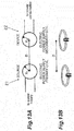
- FIGS. 13A and 13B are diagrams illustrating a concept of a wireless power transfer system.
- FIGS. 13A and 13B The concept illustrated in FIGS. 13A and 13B has been disclosed in US Patent No. 8035255 .
- electric power is supplied to a parked vehicle from a power supply apparatus.
- a vehicle has a wireless type power supply secondary coil on a bottom part thereof, and a power supply primary coil is provided below the vehicle to supply electric power to the vehicle.
- Japanese Unexamined Patent Publication No. 2012-085472 proposes to provide a vehicular charge apparatus that can implement an efficient contactless charge dispensing with a strict vehicle stop.
- the vehicular charge apparatus includes: a receiving section including a secondary coil connected to a rechargeable battery of a vehicle; a feeding section including a primary coil, installed on a ground side and configured to move toward the receiving section to fit the receiving section when opposed to the receiving section of the vehicle; positioning means for positioning the feeding section relative to the receiving section when the feeding section fits the receiving section; and feeding section power supply means disposed on the feeding section to supply power to the primary coil.
- the positioning means is inclined surface portions formed on both the receiving section and the feeding section and configured to fit each other.
- a wireless power transfer system according to the preamble of independent claim 1 is known from European Patent Application 0 874 378 A2 .
- the present disclosure describes an object power supply device capable of performing easily available power supply with a small energy loss using a simple structure.
- a wireless power transfer system of the present invention is defined in independent claim 1. Preferred embodiments are set out in the dependent claims.
- the present disclosure describes a wireless power transfer system that performs wireless power transfer, the wireless power transfer system including: a power supply primary coil capable of performing the wireless power transfer; and a power supply secondary coil capable of performing the wireless power transfer between the power supply primary coil and the power supply secondary coil, wherein the power supply secondary coil contains a secondary coil wire for the wireless power transfer and forms a secondary outer shape having a projecting surface on at least a part of the secondary outer shape, and the power supply primary coil and the power supply secondary coil are capable of performing the wireless power transfer, with the projecting surface of the secondary outer shape directed to the power supply primary coil.
- the power supply primary coil is capable of performing the wireless power transfer.
- the power supply secondary coil is capable of performing the wireless power transfer between the power supply primary coil and the power supply secondary coil.
- the power supply secondary coil contains the secondary coil wire for the wireless power transfer and forms the secondary outer shape having the projecting surface on at least a part of the secondary outer shape.
- the power supply primary coil and the power supply secondary coil are capable of performing the wireless power transfer, with the projecting surface of the secondary outer shape directed to the power supply primary coil.
- the wireless power transfer can be performed, with a relative posture between the power supply primary coil and the power supply secondary coil set to a desired posture.
- the wireless power transfer system is configured such that the secondary outer shape has a projecting curved surface on at least a part of the secondary outer shape, and the power supply primary coil and the power supply secondary coil are capable of performing the wireless power transfer, with the projecting curved surface of the secondary outer shape directed to the power supply primary coil.
- the secondary outer shape has the projecting curved surface on at least a part of the secondary outer shape.
- the power supply primary coil and the power supply secondary coil are capable of performing the wireless power transfer, with the projecting curved surface of the secondary outer shape directed to the power supply primary coil.
- the wireless power transfer can be performed, with the relative posture between the power supply primary coil and the power supply secondary coil set to the desired posture.
- the wireless power transfer system is further configured such that the secondary outer shape has a projecting curved surface on at least a part of the secondary outer shape, and a gravity center point of the power supply secondary coil is offset from a curvature center of the projecting curved surface and located on a side of the projecting curved surface.
- the secondary outer shape has the projecting curved surface on at least a part of the secondary outer shape.
- the gravity center point of the power supply secondary coil is offset from the curvature center of the projecting curved surface and located on the side of the projecting curved surface.
- the wireless power transfer can be performed, with a relative posture between the power supply primary coil and the power supply secondary coil set to a desired posture.
- the wireless power transfer system is further configured such that the power supply primary coil contains a primary coil wire for the wireless power transfer and forms a primary outer shape having a depression in at least a part of the primary outer shape, and the power supply primary coil and the power supply secondary coil are capable of performing the wireless power transfer, with the projecting surface of the secondary outer shape fit into the depression of the primary outer shape.
- the power supply primary coil contains the primary coil wire for the wireless power transfer and forms the primary outer shape having the depression in at least a part of the primary outer shape.
- the power supply primary coil and the power supply secondary coil are capable of performing the wireless power transfer, with the projecting surface of the secondary outer shape fit into the depression of the primary outer shape.
- the wireless power transfer can be performed, with a relative posture between the power supply primary coil and the power supply secondary coil set to a desired posture.
- the wireless power transfer system is further configured such that the power supply primary coil contains the primary coil wire for the wireless power transfer and forms the primary outer shape having the depression in at least the part of the primary outer shape, the depression includes a first depression and a second depression located at a center of the first depression and smaller than the first depression, and the power supply primary coil and the power supply secondary coil are capable of performing the wireless power transfer, with the projecting surface of the secondary outer shape fit into the second depression of the primary outer shape.
- the power supply primary coil contains the primary coil wire for the wireless power transfer and forms the primary outer shape having the depression in at least a part of the primary outer shape.
- the depression includes the first depression and the second depression located at the center of the first depression and smaller than the first depression.
- the power supply primary coil and the power supply secondary coil are capable of performing the wireless power transfer, with the projecting surface of the secondary outer shape fit into the second depression of the primary outer shape.
- the wireless power transfer can be performed, with a relative posture between the power supply primary coil and the power supply secondary coil set to a desired posture.
- the wireless power transfer system may include an intermediate case that supports the power supply secondary coil, wherein the secondary outer shape has a projecting curved surface with a constant radius of curvature on at least a part of the secondary outer shape, the intermediate case has an inner wall forming a recessed curved surface with a constant radius of curvature that covers the projecting curved surface of the secondary outer shape, and the power supply primary coil and the power supply secondary coil are capable of performing the wireless power transfer, with the projecting curved surface of the secondary outer shape guided by the recessed curved surface of the intermediate case and swingable.
- the intermediate case supports the power supply secondary coil.
- the secondary outer shape has the projecting curved surface with the constant radius of curvature on at least a part of the secondary outer shape.
- the intermediate case has the inner wall forming the recessed curved surface with the constant radius of curvature that covers the projecting curved surface of the secondary outer shape.
- the power supply primary coil and the power supply secondary coil are capable of performing the wireless power transfer, with the projecting curved surface of the secondary outer shape guided by the recessed curved surface of the intermediate case and swingable.
- the wireless power transfer can be performed, with a relative posture between the power supply primary coil and the power supply secondary coil set to a desired posture.
- the wireless power transfer system may include an intermediate case that supports the power supply secondary coil, wherein the secondary outer shape has a projecting curved surface with a constant radius of curvature on at least a part of the secondary outer shape, the intermediate case has an inner wall forming a recessed curved surface with a constant radius of curvature that covers the projecting curved surface of the secondary outer shape, the intermediate case contains an intermediate coil wire, and the power supply primary coil and the power supply secondary coil are capable of performing the wireless power transfer relayed by the intermediate coil wire, with the projecting curved surface of the secondary outer shape guided by the recessed curved surface of the intermediate case and swingable.
- the intermediate case supports the power supply secondary coil.
- the secondary outer shape has the projecting curved surface with the constant radius of curvature on at least a part of the secondary outer shape.
- the intermediate case has the inner wall forming the recessed curved surface with the constant radius of curvature that covers the projecting curved surface of the secondary outer shape.
- the intermediate case contains the intermediate coil wire.
- the power supply primary coil and the power supply secondary coil are capable of performing the wireless power transfer relayed by the intermediate coil wire, with the projecting curved surface of the secondary outer shape guided by the recessed curved surface of the intermediate case and swingable.
- the wireless power transfer can be performed, with a relative posture between the power supply primary coil and the power supply secondary coil set to a desired posture.
- the wireless power transfer system may be configured such that the power supply secondary coil contains a first secondary coil wire and a second secondary coil wire that are a pair of secondary coil wires, the first secondary coil wire is wound along a first virtual surface, the second secondary coil wire is wound along a second virtual surface, and the first virtual surface and the second virtual surface intersect.
- the power supply secondary coil contains the first secondary coil wire and the second secondary coil wire that are the pair of secondary coil wires.
- the first secondary coil wire is wound along the first virtual surface.
- the second secondary coil wire is wound along the second virtual surface. The first virtual surface and the second virtual surface intersect.
- the wireless power transfer can be performed, with a relative posture between the power supply primary coil and the power supply secondary coil set to a desired posture.
- An aspect of the present invention is an object power supply device that includes the above described wireless power transfer system and is capable of supplying electric power to an object in which a power receiving circuit is provided, the object power supply device also including a charging cable having an electric circuit that is electrically connectable to the power receiving circuit of the object, wherein the power supply primary coil is provided at a storage space capable of storing the object.
- the power supply primary coil is provided at the storage space capable of storing the object, and capable of performing the wireless power transfer to the power supply secondary coil.
- the charging cable has the electric circuit that is electrically connectable to the power receiving circuit of the object, and the power supply secondary coil electrically connected to the electric circuit and capable of receiving the wireless power transfer from the power supply primary coil.
- the power supply secondary coil contains the secondary coil wire for the wireless power transfer and forms the secondary outer shape having the projecting surface on at least a part of the secondary outer shape.
- the power supply primary coil and the power supply secondary coil are capable of performing the wireless power transfer, with the projecting surface of the secondary outer shape directed to the power supply primary coil.
- the wireless power transfer can be performed, with a relative posture between the power supply primary coil and the power supply secondary coil set to a desired posture.
- An aspect of the present invention is an object power supply device that includes the above described wireless power transfer system and is capable of supplying electric power to an object in which a power receiving circuit is provided, the object power supply device also including: an object support structure capable of supporting the object; and a charging cable having an electric circuit that is electrically connectable to the power receiving circuit of the object.
- the object support structure is capable of supporting the object.
- the power supply primary coil is provided at the object support structure and capable of performing the wireless power transfer to the power supply secondary coil.
- the charging cable has the electric circuit that is electrically connectable to the power receiving circuit of the object, and the power supply secondary coil electrically connected to the electric circuit and capable of receiving the wireless power transfer from the power supply primary coil.
- the power supply secondary coil contains the secondary coil wire for the wireless power transfer and forms the secondary outer shape having the projecting surface on at least a part of the secondary outer shape.
- the power supply primary coil and the power supply secondary coil are capable of performing the wireless power transfer, with the projecting surface of the secondary outer shape directed to the power supply primary coil.
- the wireless power transfer can be performed, with a relative posture between the power supply primary coil and the power supply secondary coil set to a desired posture.
- the wireless power transfer system has the following effects owing to its configuration.
- the wireless power transfer is performed, with the projecting surface formed on a part of the power supply secondary coil containing the secondary coil wire for the wireless power transfer directed to the power supply primary coil. Therefore, the wireless power transfer can be performed, with the relative posture between the power supply primary coil and the power supply secondary coil set to the desired posture.
- the wireless power transfer is performed, with the projecting curved surface formed on a part of the power supply secondary coil containing the secondary coil wire for the wireless power transfer directed to the power supply primary coil. Therefore, the wireless power transfer can be performed, with the relative posture between the power supply primary coil and the power supply secondary coil set to the desired posture.
- the wireless power transfer is performed, with the gravity center point of the power supply secondary coil offset from the curvature center of the curved surface and located on the side of the curved surface, and with the projecting curved surface formed on a part of the power supply secondary coil containing the secondary coil wire for the wireless power transfer directed to the power supply primary coil. Therefore, the wireless power transfer can be performed, with the relative posture between the power supply primary coil and the power supply secondary coil set to the desired posture.
- the wireless power transfer is performed, with the projecting surface formed on a part of the power supply secondary coil containing the secondary coil wire for the wireless power transfer directed to the power supply primary coil and fit into the depression of the power supply primary coil. Therefore, the wireless power transfer can be performed, with the relative posture between the power supply primary coil and the power supply secondary coil set to the desired posture.
- the wireless power transfer is performed, with the projecting surface formed on a part of the power supply secondary coil containing the secondary coil wire for the wireless power transfer directed to the power supply primary coil and fit into the second depression located at the center of the first depression of the power supply primary coil. Therefore, the wireless power transfer can be performed, with the relative posture between the power supply primary coil and the power supply secondary coil set to the desired posture.
- the wireless power transfer is performed, with the projecting curved surface with the constant radius of curvature formed on a part of the power supply secondary coil containing the secondary coil wire for the wireless power transfer covered by the intermediate case, and with the curved surface directed to the power supply primary coil. Therefore, the wireless power transfer can be performed, with the relative posture between the power supply primary coil and the power supply secondary coil set to the desired posture.
- the wireless power transfer is performed, with the intermediate case containing the intermediate coil wire covering the projecting curved surface with the constant radius of curvature formed on a part of the power supply secondary coil containing the secondary coil wire for the wireless power transfer, and with the curved surface directed to the power supply primary coil. Therefore, the wireless power transfer can be performed, with the relative posture between the power supply primary coil and the power supply secondary coil set to the desired posture.
- the wireless power transfer is performed, with the projecting surface formed on a part of the power supply secondary coil containing the first secondary coil wire and the second secondary coil respectively wound along the intersecting first virtual surface and second virtual surface directed to the power supply primary coil. Therefore, the wireless power transfer can be performed, with the relative posture between the power supply primary coil and the power supply secondary coil set to the desired posture.
- the object power supply device has the following effects owing to its configuration.
- the wireless power transfer is performed, with the projecting surface formed on a part of the power supply secondary coil containing the secondary coil wire for the wireless power transfer directed to the power supply primary coil provided at the storage space. Therefore, the wireless power transfer can be performed, with the relative posture between the power supply primary coil and the power supply secondary coil set to the desired posture.
- the object power supply device has the following effects owing to its configuration.
- the wireless power transfer is performed, with the projecting surface formed on a part of the power supply secondary coil containing the secondary coil wire for the wireless power transfer directed to the power supply primary coil provided at the object support structure. Therefore, the wireless power transfer can be performed, with the relative posture between the power supply primary coil and the power supply secondary coil set to the desired posture.
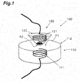
- FIG. 1 is a diagram of a wireless power transfer system according to a first example which is not claimed but is useful for understanding the present invention.
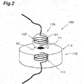
- FIG. 2 is a diagram of a wireless power transfer system according to a second example which is not claimed but is useful for understanding the present invention.
- FIG. 3 is a diagram of a wireless power transfer system according to a third example which is not claimed but is useful for understanding the present invention.
- FIG. 4 is a diagram of a wireless power transfer system according to an embodiment of the present invention.
- FIG. 5 is a diagram of a wireless power transfer system according to a fourth example which is not claimed but is useful for understanding the present invention.
- FIG. 6 is a diagram of a wireless power transfer system according to a fifth example which is not claimed but is useful for understanding the present invention.
- FIG. 7 is a diagram of a wireless power transfer system according to a sixth example which is not claimed but is useful for understanding the present invention.
- the wireless power transfer system according to the first example is a system that performs wireless power transfer.
- FIG. 1 the diagram of the wireless power transfer system according to the first example is illustrated.
- the wireless power transfer system 100 includes a power supply primary coil 110 and a power supply secondary coil 120.
- the wireless power transfer can be performed between the power supply primary coil 110 and the power supply secondary coil 120.
- the wireless power transfer can be performed from the power supply primary coil 110 to the power supply secondary coil 120.
- the wireless power transfer can be performed from the power supply secondary coil 120 to the power supply primary coil 110.
- the power supply primary coil 110 is capable of performing the wireless power transfer.
- the power supply primary coil 110 contains a primary coil wire 111 for the wireless power transfer, and forms a primary outer shape (primary shape) F1.
- the power supply primary coil 110 includes the primary coil wire 111 and a primary coil case 112.
- the primary coil wire 111 is an electric magnetic circuit in which a DC current or an AC current flows to generate a magnetic field.
- the primary coil case 112 contains the primary coil wire 111.
- the primary coil case 112 forms the primary outer shape F1.
- the primary outer shape F1 has a surface.
- the primary outer shape F1 may have a planar surface on a part of the primary outer shape F1.
- the power supply secondary coil 120 is capable of performing the wireless power transfer between the power supply primary coil 110 and the power supply secondary coil 120.
- the power supply secondary coil 120 contains a secondary coil wire 121 for the wireless power transfer, and forms a secondary outer shape (secondary shape) F2.
- the secondary outer shape F2 has a surface.
- the secondary outer shape F2 has a projecting surface on at least a part of the secondary outer shape F2.
- the power supply primary coil 110 and the power supply secondary coil 120 are capable of performing the wireless power transfer, with the projecting surface of the secondary outer shape F2 directed to the power supply primary coil 110.
- the power supply primary coil 110 and the power supply secondary coil 120 are capable of performing the wireless power transfer, with the projecting surface held by the secondary outer shape F2 directed to the planar surface held by the primary outer shape F1.
- Electric power supplied in a wireless manner from the power supply primary coil 110 can be supplied to the power supply secondary coil 120.
- FIG. 2 the diagram of the wireless power transfer system according to the second example is illustrated.
- the wireless power transfer system 100 includes a power supply primary coil 110 and a power supply secondary coil 120.
- Wireless power transfer can be performed between the power supply primary coil 110 and the power supply secondary coil 120.
- the wireless power transfer can be performed from the power supply primary coil 110 to the power supply secondary coil 120.
- the wireless power transfer can be performed from the power supply secondary coil 120 to the power supply primary coil 110.
- the power supply primary coil 110 is capable of performing the wireless power transfer.
- the power supply primary coil 110 contains a primary coil wire 111 for the wireless power transfer, and forms a primary outer shape F1.
- the power supply primary coil 110 includes the primary coil wire 111 and a primary coil case 112.
- the primary coil wire 111 is an electric magnetic circuit in which a DC current or an AC current flows to generate a magnetic field.
- the primary coil case 112 contains the primary coil wire 111.
- the primary coil case 112 forms the primary outer shape F1.
- the primary outer shape F1 has a surface.
- the primary outer shape F1 may have a planar surface on a part of the primary outer shape F1.
- the power supply secondary coil 120 is capable of performing the wireless power transfer between the power supply primary coil 110 and the power supply secondary coil 120.
- the power supply secondary coil 120 contains a secondary coil wire for the wireless power transfer, and forms a secondary outer shape F2.
- the power supply secondary coil 120 includes the secondary coil wire 121 and a secondary coil case 122.
- the secondary coil wire 121 is an electric magnetic circuit in which a DC current or an AC current flows to generate a magnetic field.
- the secondary coil case 122 contains the secondary coil wire 121.
- the secondary coil case 122 forms the secondary outer shape F2.
- the primary outer shape F1 has a surface.
- the secondary outer shape F2 has a surface.
- the secondary outer shape F2 has a projecting surface on at least a part of the secondary outer shape F2.
- the secondary outer shape F2 has a projecting curved surface on at least a part of the secondary outer shape F2.
- the secondary outer shape F2 has a spherical curved surface.
- the power supply primary coil 110 and the power supply secondary coil may be capable of performing the wireless power transfer, with the projecting curved surface of the secondary outer shape F2 directed to the power supply primary coil 110.
- the power supply primary coil 110 and the power supply secondary coil may be capable of performing the wireless power transfer, with the projecting curved surface held by the secondary outer shape F2 directed to the planar surface held by the primary outer shape F1.
- a gravity center point of the power supply secondary coil may be offset from a curvature center of the projecting curved surface and located on a side of the projecting curved surface.
- the gravity center point of the power supply secondary coil may be located between the curvature center of the projecting curved surface and the projecting curved surface.
- the power supply primary coil 110 and the power supply secondary coil 120 may be capable of performing the wireless power transfer, with the projecting curved surface of the secondary outer shape directed to the power supply primary coil 110.
- the power supply primary coil 110 and the power supply secondary coil 120 may be capable of performing the wireless power transfer, with the projecting curved surface held by the secondary outer shape F2 directed to the planar surface of the primary outer shape F1.
- the power supply secondary coil 120 has a weight on the offset position.
- the gravity center point of the power supply secondary coil 120 is located between the curvature center of the projecting curved surface and the projecting curved surface.
- Electric power supplied in a wireless manner from the power supply primary coil 110 can be supplied to the power supply secondary coil 120.
- FIG. 3 is the diagram illustrating the concept of the wireless power transfer system according to the third embodiment of the present invention.
- the wireless power transfer system 100 includes a power supply primary coil 110 and a power supply secondary coil 120.
- the wireless power transfer can be performed between the power supply primary coil 110 and the power supply secondary coil 120.
- the wireless power transfer can be performed from the power supply primary coil 110 to the power supply secondary coil 120.
- the wireless power transfer can be performed from the power supply secondary coil 120 to the power supply primary coil 110.
- the power supply primary coil 110 is capable of performing the wireless power transfer.
- the power supply primary coil 110 contains a primary coil wire 111 for the wireless power transfer, and forms a primary outer shape F1.
- the power supply primary coil 110 includes the primary coil wire 111 and a primary coil case 112.
- the primary coil wire 111 is an electric magnetic circuit in which a DC current or an AC current flows to generate a magnetic field.
- the primary coil case 112 contains the primary coil wire 111.
- the primary coil case 112 forms the primary outer shape F1.
- the primary outer shape F1 has a depression in a part of the primary outer shape F1.
- the depression may be a recessed curved surface.
- the recessed curved surface may have a radius of curvature equal to or slightly greater than a radius of curvature of a projecting curved surface held by a secondary outer shape F2 of the power supply secondary coil 120.
- the configuration of the power supply secondary coil 120 is the same as those of the wireless power transfer systems according to the first to second embodiments, the description will be omitted.
- the power supply primary coil 110 and the power supply secondary coil 120 are capable of performing the wireless power transfer, with the projecting surface held by the secondary outer shape F2 fit into the depression of the primary outer shape F1.
- Electric power supplied in a wireless manner from the power supply primary coil 110 can be supplied to the power supply secondary coil 120.
- FIG. 4 is the diagram illustrating the concept of the wireless power transfer system according to the embodiment of the present invention.
- the wireless power transfer system 100 includes a power supply primary coil 110 and a power supply secondary coil 120.
- the wireless power transfer can be performed between the power supply primary coil 110 and the power supply secondary coil 120.
- the wireless power transfer can be performed from the power supply primary coil 110 to the power supply secondary coil 120.
- the wireless power transfer can be performed from the power supply secondary coil 120 to the power supply primary coil 110.
- the power supply primary coil 110 is capable of performing the wireless power transfer.
- the power supply primary coil 110 contains a primary coil wire 111 for the wireless power transfer, and forms a primary outer shape.
- the power supply primary coil 110 includes the primary coil wire 111 and a primary coil case 112.
- the primary coil wire 111 is an electric magnetic circuit in which a DC current or an AC current flows to generate a magnetic field.
- the primary coil case 112 contains the primary coil wire 111.
- the primary coil case 112 forms the primary outer shape F1.
- the primary outer shape F1 has a depression in a part of the primary outer shape F1.
- the depression includes a first depression and a second depression.
- the second depression is located at a center of the first depression and smaller than the first depression.
- the first depression may be a recessed curved surface.
- the second depression may be a recessed curved surface.
- the recessed curved surface of the second depression may have a radius of curvature equal to or slightly greater than a radius of curvature of a projecting curved surface held by a secondary outer shape F2 of the power supply secondary coil.
- the configuration of the power supply secondary coil 120 is the same as those of the wireless power transfer systems according to the first to second embodiments, the description will be omitted.
- the power supply primary coil 110 and the power supply secondary coil 120 are capable of performing the wireless power transfer, with the projecting surface of the secondary outer shape F2 fit into the second depression of the primary outer shape F1.
- Electric power supplied in a wireless manner from the power supply primary coil 110 can be supplied to the power supply secondary coil 120.
- FIG. 5 is the diagram illustrating the concept of the wireless power transfer system according to the fifth embodiment of the present invention.
- the wireless power transfer system 100 includes a power supply primary coil 110, a power supply secondary coil 120, and an intermediate case 130.
- the wireless power transfer can be performed between the power supply primary coil 110 and the power supply secondary coil 120.
- the wireless power transfer can be performed from the power supply primary coil 110 to the power supply secondary coil 120.
- the wireless power transfer can be performed from the power supply secondary coil 120 to the power supply primary coil 110.
- the configuration of the power supply primary coil 110 is the same as those of the wireless power transfer systems according to the first to fourth embodiments, the description will be omitted.
- the configuration of the power supply secondary coil 120 is the same as that of the wireless power transfer system according to the second embodiment, the description will be omitted.
- the intermediate case 130 is a case that supports the power supply secondary coil 120.
- the intermediate case 130 has an inner wall forming a recessed curved surface with a constant radius of curvature that covers the projecting curved surface of the secondary outer shape F2.
- the intermediate case 130 forms an intermediate outer shape F3.
- the intermediate outer shape F3 may form a projecting surface on a part of the intermediate outer shape F3.
- the intermediate outer shape F3 may form a projecting curved surface on a part of the intermediate outer shape F3.
- the intermediate outer shape F3 may form a projecting curved surface with a constant radius of curvature on a part of the intermediate outer shape F3.
- the intermediate outer shape F3 may form a plane on a part of the intermediate outer shape F3.
- the power supply primary coil 110 and the power supply secondary coil 120 are capable of performing the wireless power transfer, with the projecting curved surface of the secondary outer shape F2 guided by the recessed curved surface of the intermediate case 130 and swingable.
- the power supply primary coil 110 and the power supply secondary coil 120 may be capable of performing the wireless power transfer, with the projecting surface held by the intermediate outer shape F3 directed to the power supply primary coil 110, and with the projecting curved surface of the secondary outer shape F2 guided by the recessed curved surface of the intermediate case 130 and swingable.
- the power supply primary coil 110 and the power supply secondary coil 120 may be capable of performing the wireless power transfer, with the projecting surface held by the intermediate outer shape F3 directed to the power supply primary coil 110, and with the projecting curved surface of the secondary outer shape F2 guided by the recessed curved surface of the intermediate case 130 and swingable.
- the power supply primary coil 110 and the power supply secondary coil 120 may be capable of performing the wireless power transfer, with the plane held by the intermediate outer shape F3 directed to the power supply primary coil 110, and with the projecting curved surface of the secondary outer shape F2 guided by the recessed curved surface of the intermediate case 130 and swingable.
- the power supply primary coil 110 and the power supply secondary coil 120 may be capable of performing the wireless power transfer, with the plane held by the intermediate outer shape F3 directed to a plane of the primary outer shape F1, and with the projecting curved surface of the secondary outer shape F2 guided by the recessed curved surface of the intermediate case 130 and swingable.
- Electric power supplied in a wireless manner from the power supply primary coil 110 can be supplied to the power supply secondary coil 120.
- FIG. 6 is the diagram illustrating the concept of the wireless power transfer system according to the sixth embodiment of the present invention.
- the wireless power transfer system 100 includes a power supply primary coil 110, a power supply secondary coil 120, and an intermediate case 130.
- the wireless power transfer can be performed between the power supply primary coil 110 and the power supply secondary coil 120.
- the wireless power transfer can be performed from the power supply primary coil 110 to the power supply secondary coil 120.
- the wireless power transfer can be performed from the power supply secondary coil 120 to the power supply primary coil 110.
- the configuration of the power supply primary coil 110 is the same as those of the wireless power transfer systems according to the first to fourth embodiments, the description will be omitted.
- the configuration of the power supply secondary coil 120 is the same as that of the wireless power transfer system according to the second embodiment, the description will be omitted.
- the intermediate case 130 is a case that supports the power supply secondary coil.
- the intermediate case 130 contains an intermediate coil wire 131.
- the intermediate case 130 has an inner wall forming a recessed curved surface with a constant radius of curvature that covers the projecting curved surface of the secondary outer shape.
- the intermediate case 130 forms an intermediate outer shape F3.
- the intermediate outer shape F3 may form a projecting surface on a part of the intermediate outer shape F3.
- the intermediate outer shape F3 may form a projecting curved surface on a part of the intermediate outer shape F3.
- the intermediate outer shape F3 may form a projecting curved surface with a constant radius of curvature on a part of the intermediate outer shape F3.
- the intermediate outer shape F3 may form a plane on a part of the intermediate outer shape F3.
- the power supply primary coil 110 and the power supply secondary coil 120 are capable of performing the wireless power transfer relayed by the intermediate coil wire 131.
- the power supply primary coil and the power supply secondary coil are capable of performing the wireless power transfer relayed by the intermediate coil wire, with the projecting curved surface of the secondary outer shape F2 guided by the recessed curved surface of the intermediate case 130 and swingable.
- Electric power supplied in a wireless manner from the power supply primary coil 110 can be supplied to the power supply secondary coil 120.
- the wireless power transfer system according to the sixth example is a system that performs wireless power transfer.
- FIG. 7 the diagram of the wireless power transfer system according to the sixth example is illustrated.
- the wireless power transfer system 100 includes a power supply primary coil 110 and a power supply secondary coil 120.
- the wireless power transfer can be performed between the power supply primary coil 110 and the power supply secondary coil 120.
- the wireless power transfer can be performed from the power supply primary coil 110 to the power supply secondary coil 120.
- the wireless power transfer can be performed from the power supply secondary coil 120 to the power supply primary coil 110.
- the configuration of the power supply primary coil 110 is the same as those of the wireless power transfer systems according to the first to fourth embodiments, the description will be omitted.
- the power supply secondary coil 120 is capable of performing the wireless power transfer between the power supply primary coil 110 and the power supply secondary coil 120.
- the power supply secondary coil 120 contains a pair of secondary coil wires 121 for the wireless power transfer, and forms a secondary outer shape.
- the pair of secondary coil wires 121 includes a first secondary coil wire 121a and a second secondary coil wire 121b.
- the first secondary coil wire 121a is wound along a first virtual surface A.
- the second secondary coil wire 121b is wound along a second virtual surface B.
- the first virtual surface A and the second virtual surface B intersect.
- the first virtual surface A and the second virtual surface B may be orthogonal to each other.
- the secondary outer shape F2 has a projecting surface on at least a part of the secondary outer shape F2.
- Electric power supplied in a wireless manner from the power supply primary coil 110 can be supplied to the power supply secondary coil 120.
- FIGS. 8A and 8B are diagrams of the object power supply device according to the first example.
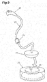
- FIG. 9 is a partial view of the object power supply device according to the third example.
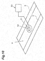
- FIG. 10 is a perspective view of the object power supply device according to the first embodiment of the present invention.
- the object power supply device is a device that can supply electric power to an object.
- the object is driven by electric power, examples of which include electric apparatuses, vehicles, movable bodies, and ships or the like.
- the object power supply device includes a charging cable 20.
- the object power supply device may include the charging cable 20 and a power supply primary coil 21.
- the object power supply device may include the charging cable 20, the power supply primary coil 21, and a drive circuit 30.
- the vehicle 10 is a movable body capable of receiving power supply.
- the vehicle 10 is a car capable of receiving power supply.
- the vehicle 10 includes a vehicle main body 11 and a power receiving circuit 12.
- the vehicle 10 may include the vehicle main body 11, the power receiving circuit 12, and a power supply plug receiver 13.
- the vehicle main body 11 is the vehicle itself.
- the vehicle is an electric car and a hybrid car or the like.
- the power receiving circuit 12 is an electric apparatus that receives electric power supplied from the outside.
- the power receiving circuit 12 charges an incorporated battery of the vehicle main body 11 with electric power supplied from the outside.
- the power supply plug receiver 13 is an electric element that is joined to a power supply plug 24 mechanically, electrically, detachably, and attachably.
- the charging cable 20 is a cable that conducts electric power to the vehicle for power supply.
- the charging cable 20 includes a power supply secondary coil 22 and an electric circuit 23.
- the charging cable 20 may include the power supply secondary coil 22, the electric circuit 23, and the power supply plug 24.
- the charging cable 20 may include the power supply secondary coil 22, the electric circuit 23, the power supply plug 24, and a converter unit 25.
- the power supply secondary coil 22 is an electric element electrically connected to the electric circuit 23 which will be described later, and capable of receiving wireless power transfer from the power supply primary coil 21.
- the power supply secondary coil can be separated from the vehicle, with the electric circuit electrically connected to the power receiving circuit.
- the power supply secondary coil can be separated from the vehicle by a distance by which the electric circuit 23 extends, with the electric circuit electrically connected to the power receiving circuit.
- electric power may be supplied in a wireless manner from the power supply primary coil 21 placed below the power supply secondary coil 22.
- electric power is supplied in a wireless manner using a magnetic field resonance type from the power supply primary coil 21 placed below the power supply secondary coil 22.
- electric power is supplied in a wireless manner using an electric field resonance type from the power supply primary coil 21 placed below the power supply secondary coil 22.
- electric power is supplied in a wireless manner using an electromagnetic induction type from the power supply primary coil 21 placed below the power supply secondary coil 22.
- the electric circuit 23 is an electric element that is electrically connectable to the power receiving circuit 12 of the vehicle 10.
- the electric circuit 23 conducts, to the power receiving circuit 12 of the vehicle 10, electric power supplied in a wireless manner to the power supply secondary coil 22.
- the electric circuit 23 is an electric cable, one end of which may be directly and electrically connected to the power receiving circuit 12 of the vehicle 10, and the other end may be electrically connected to the power supply secondary coil 22.
- the electric circuit 23 is an electric cable housed inside the vehicle 10. The electric cable is pulled to be drawn out of the vehicle 10.
- FIG. 8A it is illustrated that the electric circuit is drawn out of the vehicle 10.
- the electric circuit 23 is an electric cable, one end of which may be electrically coupled to the power receiving circuit 12 of the vehicle 10 via the power supply plug 24, and the other end may be electrically connected to the power supply secondary coil 22.
- the power supply plug 24 is an electric element that is connected to the power supply plug receiver 13 of the vehicle 10 detachably, attachably, electrically, and mechanically.
- FIG. 8B it is illustrated that the power supply plug 24 is connected to the power supply plug receiver 13 of the vehicle.
- the converter unit 25 is an electric element that converts an electrical specification of electric power supplied in a wireless manner to the power supply secondary coil 22 to an electrical specification of electric power of the power receiving circuit 12 of the vehicle 10.
- the converter unit 25 may convert a frequency, a voltage, and a phase of electric power supplied in a wireless manner to the power supply secondary coil 22 to a frequency, a voltage, and a phase of electric power of the power receiving circuit 12 of the vehicle 10.
- the converter unit 25 may rectify and convert a voltage and a phase of electric power supplied in a wireless manner to the power supply secondary coil 22 to a DC current of a predetermined voltage of electric power of the power receiving circuit 12 of the vehicle 10.
- the power supply primary coil 21 is capable of performing the wireless power transfer to the power supply secondary coil 22.
- the power supply primary coil 21 is provided at a storage space R that is a space in which the vehicle is stored, and capable of performing the wireless power transfer to the power supply secondary coil 22.
- the drive circuit 30 is a circuit that drives the power supply primary coil 21.
- the drive circuit 30 is a circuit that supplies electric power to the power supply primary coil 21 to drive the power supply primary coil 21.
- the drive circuit 30 supplies electric power to the power supply primary coil 21 to drive the power supply primary coil 21, the power supply primary coil generates a magnetic field.
- the drive circuit 30 When the drive circuit 30 appropriately drives the power supply primary coil 21, the wireless power transfer can be efficiently performed.
- the storage space R is a space for storing the vehicle 10.
- a mark 42 may be drawn at a position where the power supply primary coil 21 is provided.
- the wireless power transfer can be performed from the power supply primary coil 21 to the power supply secondary coil 22.
- FIG. 10 it is illustrated that the cross mark 42 is drawn at the position of the storage space R where the power supply primary coil 21 is provided.
- a depression 43 may be formed in a position where the power supply primary coil 21 is provided.
- the wireless power transfer can be performed from the power supply primary coil 21 to the power supply secondary coil 22.
- the depression 43 may be a hole into which a part of the secondary outer shape of the power supply secondary coil 22 is fit.
- the depression 43 may be a cone-shaped hole, a central part of which is deepened when viewed from above.
- FIG. 9 it is illustrated that the bowl-shaped depression 43 is formed in an upper part of the power supply primary coil 21.
- a predetermined signal may be output.
- a sensor provided at the storage space detects that the vehicle 10 is stored at the storage space.
- the drive circuit 30 determines that a load acting on the power supply primary coil 21 is small, it is determined that the wireless power transfer cannot be performed from the power supply primary coil 21 to the power supply secondary coil 22.
- the predetermined signal When the predetermined signal is output, a driver or an occupant of the vehicle 10 is notified of that fact by sound or display.
- the vehicle 10 enters the storage space R and stops.
- the charging cable 20 is drawn out, and the power supply secondary coil 22 is placed near the power supply primary coil 21.
- the power supply secondary coil 22 is placed in accordance with the mark 42.
- the power supply secondary coil 22 is placed in the depression 43.
- the power supply plug 24 is inserted into the power supply plug receiver 13.
- the drive circuit 30 performs driving so that the wireless power transfer is performed from the power supply primary coil 21 to the power supply secondary coil 22.
- Electric power supplied in a wireless manner from the power supply primary coil 21 to the power supply secondary coil 22 is supplied to the power receiving circuit 12 via the charging cable 20.
- an AC current having a predetermined frequency and a predetermined voltage may be supplied to the power receiving circuit 12 via the charging cable 20.
- a DC current having a predetermined voltage may be supplied to the power receiving circuit 12 via the charging cable 20.
- the charging cable 20 is tidied up.
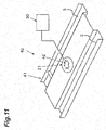
- FIG. 11 is a perspective view of the object power supply device according to the second embodiment of the present invention.
- the object power supply device is a device that can supply electric power to an object.
- the object is driven by electric power, examples of which include electric apparatuses, vehicles, movable bodies, and ships or the like.
- the object power supply device includes a charging cable 20 and an object support structure 40.
- the object power supply device may include the charging cable 20, a power supply primary coil 21, and the object support structure 40.
- the object power supply device may include the charging cable 20, the power supply primary coil 21, a drive circuit 30, and the object support structure 40.
- the configurations of the vehicle 10, the charging cable 20, the power supply primary coil 21, and the drive circuit 30 are the same as those of the object power supply device according to the first embodiment, the description will be omitted.
- the object support structure 40 is a structure that supports the vehicle 10.
- the object support structure 40 includes an object support structure main body 41.
- the object support structure 40 includes the object support structure main body 41 and a mark 42.
- the object support structure 40 includes the object support structure main body 41 and a depression 43.
- the object support structure 40 includes the object support structure main body 41, the mark 42, and the depression 43.
- FIG. 11 an example of the object support structure main body 41 is illustrated.
- the object support structure main body 41 forms a pair of left and right running surfaces S.
- the vehicle rolls wheels to the running surfaces S to load onto the object support structure 40.
- a wheel stopper is provided on the running surface S so as to prevent the wheels from rolling.
- the pair of left and right running surfaces S is a part that supports each of a pair of front and rear wheels of the vehicle 10.
- the pair of left and right running surfaces S integrally supports the vehicle 10.
- the power supply secondary coil 22 is the same as one of those of the wireless power transfer systems according to the first to seventh embodiments, the description will be omitted.
- the shape of the depression 43 is the same as the shapes of the depressions of the wireless power transfer systems according to the third to seventh embodiments, the description will be omitted.
- a predetermined signal may be output.
- a sensor provided at the object support structure 40 detects that the vehicle 10 is stored at a storage space.
- the drive circuit 30 determines that a load acting on the power supply primary coil 21 is small, it is determined that the wireless power transfer cannot be performed from the power supply primary coil 21 to the power supply secondary coil 22.
- the predetermined signal When the predetermined signal is output, a driver or an occupant of the vehicle 10 is notified of that fact by sound or display.
- FIG. 12 is a perspective view of the object power supply device according to the third example.
- the object power supply device is a device that can supply electric power to an object.
- the object is driven by electric power, examples of which include electric apparatuses, vehicles, movable bodies, and ships or the like.
- the object power supply device includes a charging cable 20 and an object support structure 40.
- the object power supply device may include the charging cable 20, a power supply primary coil 21, and the object support structure 40.
- the object power supply device may include the charging cable 20, the power supply primary coil 21, a drive circuit 30, and the object support structure 40.
- the configurations of the vehicle 10, the charging cable 20, the power supply primary coil 21, and the drive circuit 30 are the same as those of the object power supply device according to the first embodiment, the description will be omitted.
- the object support structure 40 is a structure that supports the vehicle 10.
- the object support structure 40 includes an object support structure main body 41.
- the object support structure 40 includes the object support structure main body 41 and a mark 42.
- the object support structure 40 includes the object support structure main body 41 and a depression 43.
- the object support structure 40 includes the object support structure main body 41, the mark 42, and the depression 43.
- the object support structure main body 41 may be a structure having a substantially quadrilateral shape when viewed from above that holds wheels of the vehicle 10 to support the vehicle, and may be provided with a void Q having a predetermined contour K and penetrating in a vertical direction.
- the vehicle support structure main body 41 is a so-called pallet, and provided with the void Q in a central part of the pallet when viewed from above.
- the void Q is surrounded by the contour K.
- the pallet rolls the wheels provided at a lower part thereof, and can move between a carrying device of the pallet and a parking space.
- the power supply primary coil 21 performs the wireless power transfer to the power supply secondary coil 22 via the void Q surrounded by the contour K.
- the power supply primary coil 21 may be surrounded by the contour K.
- FIG. 12 an example of the object support structure main body 41 is illustrated.
- the object support structure main body 41 forms a pair of left and right running surfaces S.
- the vehicle rolls the wheels to the running surfaces S to load onto the object support structure 40.
- a wheel stopper is provided on the running surface S so as to prevent the wheels from rolling.
- the pair of left and right running surfaces S is a part that supports each of a pair of front and rear wheels of the vehicle 10.
- the pair of left and right running surfaces S integrally supports the vehicle 10.
- the wireless power transfer system according to the embodiment of the present invention has the following effects owing to its configuration.
- the wireless power transfer is performed, with the projecting surface formed on a part of the power supply secondary coil 120 containing the secondary coil wire 121 for the wireless power transfer directed to the power supply primary coil 110. Therefore, the wireless power transfer can be performed, with a relative posture between the power supply primary coil 110 and the power supply secondary coil 120 set to a desired posture.
- the wireless power transfer is performed, with the projecting curved surface formed on a part of the power supply secondary coil 120 containing the secondary coil wire 121 for the wireless power transfer directed to the power supply primary coil 110. Therefore, the wireless power transfer can be performed, with the relative posture between the power supply primary coil 110 and the power supply secondary coil 120 set to the desired posture.
- the wireless power transfer is performed, with the gravity center point of the power supply secondary coil 120 located between the curvature center of the curved surface and the curved surface, and with the projecting curved surface formed on a part of the power supply secondary coil 120 containing the secondary coil wire 121 for the wireless power transfer directed to the power supply primary coil 110. Therefore, the wireless power transfer can be performed, with the relative posture between the power supply primary coil 110 and the power supply secondary coil 120 set to the desired posture.
- the wireless power transfer is performed, with the projecting surface formed on a part of the power supply secondary coil 120 containing the secondary coil wire 121 for the wireless power transfer directed to the power supply primary coil 110 and fit into the depression of the power supply primary coil 110. Therefore, the wireless power transfer can be performed, with the relative posture between the power supply primary coil 110 and the power supply secondary coil 120 set to the desired posture.
- the wireless power transfer is performed, with the projecting surface formed on a part of the power supply secondary coil 120 containing the secondary coil wire 121 for the wireless power transfer directed to the power supply primary coil 110 and fit into the second depression located at the center of the first depression of the power supply primary coil 110. Therefore, the wireless power transfer can be performed, with the relative posture between the power supply primary coil 110 and the power supply secondary coil 120 set to the desired posture.
- the wireless power transfer is performed, with the projecting curved surface with the constant radius of curvature formed on a part of the power supply secondary coil 120 containing the secondary coil wire 121 for the wireless power transfer covered by the intermediate case, and with the curved surface directed to the power supply primary coil 110. Therefore, the wireless power transfer can be performed, with the relative posture between the power supply primary coil 110 and the power supply secondary coil 120 set to the desired posture.
- the wireless power transfer is performed, with the intermediate case 130 containing the intermediate coil wire covering the projecting curved surface with the constant radius of curvature formed on a part of the power supply secondary coil 120 containing the secondary coil wire 121 for the wireless power transfer, and with the curved surface directed to the power supply primary coil 110. Therefore, the wireless power transfer can be performed, with the relative posture between the power supply primary coil 110 and the power supply secondary coil 120 set to the desired posture.
- the wireless power transfer is performed, with the projecting surface formed on a part of the power supply secondary coil 120 containing the first secondary coil wire 121a and the second secondary coil 121b respectively wound along the intersecting first virtual surface A and second virtual surface B directed to the power supply primary coil 110. Therefore, the wireless power transfer can be performed, with the relative posture between the power supply primary coil 110 and the power supply secondary coil 120 set to the desired posture.
- the object power supply device in which the storage space is provided according to the embodiment of the present invention has the following effects owing to its configuration.
- the wireless power transfer is performed, with the projecting surface formed on a part of the power supply secondary coil 22 containing the secondary coil wire for the wireless power transfer directed to the power supply primary coil 21 provided at the storage space R. Therefore, the wireless power transfer can be performed, with a relative posture between the power supply primary coil 21 and the power supply secondary coil 22 set to a desired posture.
- the wireless power transfer is performed, with the projecting curved surface formed on a part of the power supply secondary coil 22 containing the secondary coil wire for the wireless power transfer directed to the power supply primary coil 21 provided at the storage space R. Therefore, the wireless power transfer can be performed, with the relative posture between the power supply primary coil 21 and the power supply secondary coil 22 set to the desired posture.
- the wireless power transfer is performed, with the gravity center point of the power supply secondary coil 22 located between the curvature center of the curved surface and the curved surface, and with the projecting curved surface formed on a part of the power supply secondary coil 22 containing the secondary coil wire for the wireless power transfer directed to the power supply primary coil 21 provided at the storage space R. Therefore, the wireless power transfer can be performed, with the relative posture between the power supply primary coil 21 and the power supply secondary coil 22 set to the desired posture.
- the wireless power transfer is performed, with the projecting surface formed on a part of the power supply secondary coil 22 containing the secondary coil wire for the wireless power transfer directed to the power supply primary coil 21 provided at the storage space and fit into the depression 43 of the storage space. Therefore, the wireless power transfer can be performed, with the relative posture between the power supply primary coil 21 and the power supply secondary coil 22 set to the desired posture.
- the wireless power transfer is performed, with the projecting surface formed on a part of the power supply secondary coil 22 containing the secondary coil wire for the wireless power transfer directed to the power supply primary coil 21 provided at the storage space and fit into the second depression located at the center of the first depression of the storage space R. Therefore, the wireless power transfer can be performed, with the relative posture between the power supply primary coil 21 and the power supply secondary coil 22 set to the desired posture.
- the wireless power transfer is performed, with the projecting curved surface with the constant radius of curvature formed on a part of the power supply secondary coil 22 containing the secondary coil wire for the wireless power transfer covered by the intermediate case, and with the curved surface directed to the power supply primary coil 21 provided at the storage space R. Therefore, the wireless power transfer can be performed, with the relative posture between the power supply primary coil 21 and the power supply secondary coil 22 set to the desired posture.
- the wireless power transfer is performed, with the intermediate case containing the intermediate coil wire covering the projecting curved surface with the constant radius of curvature formed on a part of the power supply secondary coil 22 containing the secondary coil wire for the wireless power transfer, and with the curved surface directed to the power supply primary coil 21. Therefore, the wireless power transfer can be performed, with the relative posture between the power supply primary coil 21 and the power supply secondary coil 22 set to the desired posture.
- the wireless power transfer is performed, with the projecting surface formed on a part of the power supply secondary coil 22 containing the first secondary coil wire and the second secondary coil respectively wound along the intersecting first virtual surface and second virtual surface directed to the power supply primary coil 21 provided at the storage space. Therefore, the wireless power transfer can be performed, with the relative posture between the power supply primary coil 21 and the power supply secondary coil 22 set to the desired posture.
- the signal is output in a case where the wireless power transfer cannot be performed from when the vehicle 10 is stored until a predetermined period of time has elapsed. Therefore, it is possible to notify that the power supply secondary coil 22 is forgotten to be placed or that the power supply secondary coil 22 has been placed at an inappropriate place.
- the object power supply device in which the object support structure is provided according to the embodiment of the present invention has the following effects owing to its configuration.
- the wireless power transfer is performed, with the projecting surface formed on a part of the power supply secondary coil 22 containing the secondary coil wire for the wireless power transfer directed to the power supply primary coil 21 provided at the object support structure 40. Therefore, the wireless power transfer can be performed, with the relative posture between the power supply primary coil 21 and the power supply secondary coil 22 set to the desired posture.
- the wireless power transfer is performed, with the projecting curved surface formed on a part of the power supply secondary coil 22 containing the secondary coil wire for the wireless power transfer directed to the power supply primary coil 21 provided at the object support structure 40. Therefore, the wireless power transfer can be performed, with the relative posture between the power supply primary coil 21 and the power supply secondary coil 22 set to the desired posture.
- the wireless power transfer is performed, with the gravity center point of the power supply secondary coil 22 located between the curvature center of the curved surface and the curved surface, and with the projecting curved surface formed on a part of the power supply secondary coil 22 containing the secondary coil wire for the wireless power transfer directed to the power supply primary coil 21 provided at the object support structure 40. Therefore, the wireless power transfer can be performed, with the relative posture between the power supply primary coil 21 and the power supply secondary coil 22 set to the desired posture.
- the wireless power transfer is performed, with the projecting surface formed on a part of the power supply secondary coil 22 containing the secondary coil wire for the wireless power transfer directed to the power supply primary coil 21 provided at the object support structure 40 and fit into the depression 43 of the object support structure 40. Therefore, the wireless power transfer can be performed, with the relative posture between the power supply primary coil 21 and the power supply secondary coil 22 set to the desired posture.
- the wireless power transfer is performed, with the projecting surface formed on a part of the power supply secondary coil 22 containing the secondary coil wire for the wireless power transfer directed to the power supply primary coil 21 provided at the object support structure 40 and fit into the second depression located at the center of the first depression of the object support structure. Therefore, the wireless power transfer can be performed, with the relative posture between the power supply primary coil 21 and the power supply secondary coil 22 set to the desired posture.
- the wireless power transfer is performed, with the projecting curved surface with the constant radius of curvature formed on a part of the power supply secondary coil 22 containing the secondary coil wire for the wireless power transfer covered by the intermediate case, and with the curved surface directed to the power supply primary coil provided at the object support structure 40. Therefore, the wireless power transfer can be performed, with the relative posture between the power supply primary coil 21 and the power supply secondary coil 22 set to the desired posture.
- the wireless power transfer is performed, with the intermediate case containing the intermediate coil wire covering the projecting curved surface with the constant radius of curvature formed on a part of the power supply secondary coil 22 containing the secondary coil wire for the wireless power transfer, and with the curved surface directed to the power supply primary coil. Therefore, the wireless power transfer can be performed, with the relative posture between the power supply primary coil 21 and the power supply secondary coil 22 set to the desired posture.
- the wireless power transfer is performed, with the projecting surface formed on a part of the power supply secondary coil 22 containing the first secondary coil wire and the second secondary coil respectively wound along the intersecting first virtual surface and second virtual surface directed to the power supply primary coil 21 provided at the object support structure 40. Therefore, the wireless power transfer can be performed, with the relative posture between the power supply primary coil 21 and the power supply secondary coil 22 set to the desired posture.
- the signal is output in a case where the wireless power transfer cannot be performed from when the vehicle 10 is stored until a predetermined period of time has elapsed. Therefore, it is possible to notify that the power supply secondary coil 22 is forgotten to be placed or that the power supply secondary coil 22 has been placed at an inappropriate place.
- the present invention is not limited to the above-mentioned embodiments, and can be variously changed in a range not deviating from the gist of the invention.
- the present invention is not limited to this exemplary case.
- the object is electric apparatuses, vehicles, movable bodies, and ships or the like.
- the storage space is a parking space
- the object support structure is a pallet.
- the storage space is a berth
- the object support structure is a shipway.
- the storage space is a wet place
- the object support structure is a stand for the electric apparatus.
- a plate made of a material that does not affect a magnetic field may cover the void Q.
- the present invention is not limited to this exemplary case.
- the moving mechanism may include a circulation mechanism such as a box circulation parking device, a horizontal circulation parking device, a merry-go-round parking device, an elevator sliding parking device, a plane reciprocating parking device, a transporting storage parking device, and a two-stage or multiple-stage parking device.
Landscapes
- Engineering & Computer Science (AREA)
- Power Engineering (AREA)
- Transportation (AREA)
- Mechanical Engineering (AREA)
- Computer Networks & Wireless Communication (AREA)
- Charge And Discharge Circuits For Batteries Or The Like (AREA)
- Current-Collector Devices For Electrically Propelled Vehicles (AREA)
- Life Sciences & Earth Sciences (AREA)
- Sustainable Development (AREA)
- Sustainable Energy (AREA)
Claims (7)
- Ein drahtloses Energieübertragungssystem (100), das eine drahtlose Energieübertragung durchführt, wobei das drahtlose Energieübertragungssystem (100) umfasst:eine Energieversorgungsprimärspule (110), befähigt die drahtlose Energieübertragung durchzuführen; undeine Energieversorgungssekundärspule (120), die befähigt ist, die drahtlose Energieübertragung zwischen der Energieversorgungsprimärspule (110) und der Energieversorgungssekundärspule (120) durchzuführen, wobeidie Energieversorgungssekundärspule (120) einen Sekundärspulendraht (121) für die drahtlose Energieübertragung enthält und eine Sekundäraußenform (F2) mit einer vorstehenden Fläche auf mindestens einem Teil der Sekundäraußenform (F2) bildet unddie Energieversorgungsprimärspule (110) und die Energieversorgungssekundärspule (120) befähigt sind, die drahtlose Energieübertragung durchzuführen, wobei die vorstehende Fläche der Sekundäraußenform (F2) auf die Energieversorgungsprimärspule (110) gerichtet ist,dadurch gekennzeichnet dassdie vorstehende Fläche eine vorstehende gekrümmte Fläche ist,ein Schwerpunkt der Energieversorgungssekundärspule (120) von einem Krümmungszentrum der vorstehenden gekrümmten Fläche versetzt ist und sich auf einer Seite der vorstehenden gekrümmten Fläche befindet,die Energieversorgungsprimärspule (110) einen Primärspulendraht für die drahtlose Energieübertragung enthält und eine Primäraußenform (F1) mit einer Vertiefung (43) in mindestens einem Teil der Primäraußenform (F1) bildet,die Vertiefung (43) eine erste Vertiefung umfasst und eine zweite Vertiefung, die sich in einem Zentrum der ersten Vertiefung befindet und kleiner ist als die erste Vertiefung ist, unddie Energieversorgungsprimärspule (110) und die Energieversorgungssekundärspule (120) befähigt sind, die drahtlose Energieübertragung durchzuführen, wobei die hervorstehende Fläche der Sekundäraußenform (F2) in die zweite Vertiefung der Primäraußenform (F1) passt.
- Die drahtloses Energieübertragungssystem (100) gemäß Anspruch 1, umfasst ein Zwischengehäuse (130), welches die Energieversorgungssekundärspule (120) lagert, wobei
die Sekundäraußenform (F2) eine vorstehende gekrümmte Oberfläche mit einem konstanten Krümmungsradius auf mindestens einem Teil der Sekundäraußenform (F2) hat,
das Zwischengehäuse (130) eine Innenwand hat, die eine zurückgesetzte gekrümmte Oberfläche mit einem konstanten Krümmungsradius bildet, welche die vorstehende gekrümmte Oberfläche der Sekundäraußenform (F2) bedeckt, und
die Energieversorgungsprimärspule (110) und die Energieversorgungssekundärspule (120) befähigt sind, die drahtlose Energieübertragung durchzuführen, wobei die vorstehende gekrümmte Oberfläche der Sekundäraußenform (F2) durch die zurückgesetzte gekrümmte Oberfläche des Zwischengehäuses schwenkbar geführt wird (130). - Die drahtloses Energieübertragungssystem (100) gemäß Anspruch 2, wobei
das Zwischengehäuse (130) einen Zwischenspulendraht (131) enthält und
die Energieversorgungsprimärspule (110) und die Energieversorgungssekundärspule (120) befähigt sind, die drahtlose Energieübertragung durchzuführen, die von dem Zwischenspulendraht (131) weitergeleitet wird. - Die drahtloses Energieübertragungssystem (100) gemäß Anspruch 3, wobei
die Energieversorgungssekundärspule (120) einen ersten Sekundärspulendraht (121a) und einen zweiten Sekundärspulendraht (121b) enthält, welche ein Paar von Sekundärspulendrähten (121) sind,
der erste Sekundärspulendraht (121a) entlang einer ersten virtuellen Oberfläche (A) gewickelt ist,
der zweite Sekundärspulendraht (121b) entlang einer zweiten virtuellen Oberfläche (B) gewickelt ist und
die erste virtuelle Oberfläche (A) und die zweite virtuelle Oberfläche (B) sich schneiden. - Eine Energieversorgungsvorrichtung für ein Objekt, welche das drahtlose Energieübertragungssystem (100) gemäß Anspruch 1 umfasst und befähigt ist, einem Objekt, in dem eine Energieempfangsschaltung (12) vorgesehen ist, elektrische Energie zuzuführen, wobei die Energieversorgungsvorrichtung für ein Objekt ferner umfasst:ein Ladekabel (20) mit einer elektrischen Schaltung (23), die elektrisch mit der Energieempfangsschaltung (12) des Objekts verbindbar ist, und die Energieversorgungssekundärspule (22, 120) elektrisch mit der elektrischen Schaltung (23) verbunden ist und befähigt ist die drahtlosen Energieübertragung von der primären Energieversorgungsprimärspule (21, 110) zu empfangen, wobeidie Energieversorgungsprimärspule (21, 110) an einem Lagerort (R) vorgesehen ist, welcher das Objekt lagern kann.
- Die Energieversorgungsvorrichtung für ein Objektgemäß Anspruch 5, wobei
der Lagerort (R) die Primäraußenform (F1) mit der Vertiefung (43) in mindestens dem Teil der Position, in welcher die Energieversorgungsprimärspule (110) vorgesehen ist, bildet. - Eine Energieversorgungsvorrichtung für ein Objekt, welche das drahtlose Energieübertragungssystem (100) gemäß Anspruch 1 umfasst und befähigt ist, einem Objekt, in dem eine Energieempfangsschaltung (12) vorgesehen ist, elektrische Energie zuzuführen, wobei die Energieversorgungsvorrichtung für ein Objekt ferner umfasst:eine Objektlagerstruktur (40), die das Objekt lagern kann;ein Ladekabel (20) mit einer elektrischen Schaltung (23), die elektrisch mit der Energieempfangsschaltung (12) des Objekts verbindbar ist, und die Energieversorgungssekundärspule (22, 120) elektrisch mit der elektrischen Schaltung (23) verbunden ist und befähigt ist die drahtlosen Energieübertragung von der primären Energieversorgungsprimärspule (21, 110) zu empfangen, wobeidie Energieversorgungsprimärspule (21, 110) an der Objektträgerstruktur vorgesehen ist.
Applications Claiming Priority (2)
| Application Number | Priority Date | Filing Date | Title |
|---|---|---|---|
| JP2014064848A JP6236193B2 (ja) | 2014-03-26 | 2014-03-26 | 非接触給電システムと対象物給電装置 |
| PCT/JP2015/059224 WO2015147094A1 (ja) | 2014-03-26 | 2015-03-25 | 非接触給電システムと対象物給電装置 |
Publications (3)
| Publication Number | Publication Date |
|---|---|
| EP3131177A1 EP3131177A1 (de) | 2017-02-15 |
| EP3131177A4 EP3131177A4 (de) | 2018-01-03 |
| EP3131177B1 true EP3131177B1 (de) | 2019-06-19 |
Family
ID=54195604
Family Applications (1)
| Application Number | Title | Priority Date | Filing Date |
|---|---|---|---|
| EP15768779.9A Active EP3131177B1 (de) | 2014-03-26 | 2015-03-25 | Kabelloses energieversorgungssystem und energieversorgungssystem für ein objekt |
Country Status (5)
| Country | Link |
|---|---|
| US (1) | US10348118B2 (de) |
| EP (1) | EP3131177B1 (de) |
| JP (1) | JP6236193B2 (de) |
| CN (1) | CN106103181B (de) |
| WO (1) | WO2015147094A1 (de) |
Families Citing this family (6)
| Publication number | Priority date | Publication date | Assignee | Title |
|---|---|---|---|---|
| JP6043462B2 (ja) * | 2012-09-27 | 2016-12-14 | Ihi運搬機械株式会社 | 車両給電装置 |
| EP3401154A1 (de) * | 2017-05-11 | 2018-11-14 | MAGNA STEYR Fahrzeugtechnik AG & Co KG | Fahrzeugseitige ladevorrichtung für induktives laden |
| DE102017117418A1 (de) * | 2017-08-01 | 2019-02-07 | Feaam Gmbh | Primärseitige Ladevorrichtung, sekundärseitige Ladevorrichtung und Verfahren zum Laden einer Batterie für ein Fahrzeug mit einem elektrischen Antrieb |
| IT201900002979A1 (it) * | 2019-03-01 | 2020-09-01 | Fca Italy Spa | "Veicolo elettrico provvisto di connettore terminale rimovibile, con cavo a scomparsa, per la ricarica della batteria del veicolo" |
| EP4313668A1 (de) * | 2021-04-01 | 2024-02-07 | Veturex Inc. | Steckmodul zum drahtlosen laden |
| TWI819902B (zh) * | 2022-11-21 | 2023-10-21 | 國立成功大學 | 無線充電裝置及系統 |
Family Cites Families (17)
| Publication number | Priority date | Publication date | Assignee | Title |
|---|---|---|---|---|
| US5506489A (en) * | 1994-04-29 | 1996-04-09 | Hughes Aircraft Company | Inductive coupler having a tactile feel |
| JPH10304583A (ja) * | 1997-04-25 | 1998-11-13 | Sumitomo Wiring Syst Ltd | 電気自動車充電用コネクタ |
| JP2002305121A (ja) | 2000-11-06 | 2002-10-18 | Nec Tokin Corp | 非接触電力伝送装置 |
| KR20100130215A (ko) * | 2008-03-17 | 2010-12-10 | 파우워매트 엘티디. | 유도송전장치 |
| WO2010036980A1 (en) | 2008-09-27 | 2010-04-01 | Witricity Corporation | Wireless energy transfer systems |
| JP5349069B2 (ja) * | 2009-02-09 | 2013-11-20 | 株式会社豊田自動織機 | 非接触電力伝送装置 |
| KR101091515B1 (ko) | 2009-09-14 | 2011-12-08 | 대성전기공업 주식회사 | 차량의 원격 터치 패드 장치 및 그 제어 방법 |
| JP5480573B2 (ja) * | 2009-09-25 | 2014-04-23 | パナソニック株式会社 | 非接触充電システム |
| CN101673962A (zh) * | 2009-10-14 | 2010-03-17 | 奇瑞汽车股份有限公司 | 电动汽车无线充电系统 |
| JP5559518B2 (ja) | 2009-10-30 | 2014-07-23 | 富士変速機株式会社 | 立体駐車装置及び電気自動車の非接触式充電装置 |
| JP5139469B2 (ja) * | 2010-04-27 | 2013-02-06 | 株式会社日本自動車部品総合研究所 | コイルユニットおよび非接触給電システム |
| JP5574107B2 (ja) * | 2010-10-13 | 2014-08-20 | 三菱自動車工業株式会社 | 車両用充電装置 |
| US9184633B2 (en) * | 2011-02-03 | 2015-11-10 | Denso Corporation | Non-contact power supply control device, non-contact power supply system, and non-contact power charge system |
| JP2012223027A (ja) * | 2011-04-12 | 2012-11-12 | Sanyo Electric Co Ltd | 無接点式の充電アダプタ |
| CN202210703U (zh) * | 2011-08-18 | 2012-05-02 | 北汽福田汽车股份有限公司 | 感应充电装置、非接触式充电系统及电动汽车 |
| JP5852873B2 (ja) | 2011-12-16 | 2016-02-03 | Udトラックス株式会社 | 非接触給電システム |
| JP5938288B2 (ja) * | 2012-07-19 | 2016-06-22 | 株式会社日立パワーソリューションズ | 無線給電装置 |
-
2014
- 2014-03-26 JP JP2014064848A patent/JP6236193B2/ja active Active
-
2015
- 2015-03-25 WO PCT/JP2015/059224 patent/WO2015147094A1/ja not_active Ceased
- 2015-03-25 CN CN201580014795.4A patent/CN106103181B/zh active Active
- 2015-03-25 EP EP15768779.9A patent/EP3131177B1/de active Active
-
2016
- 2016-09-21 US US15/271,910 patent/US10348118B2/en active Active
Non-Patent Citations (1)
| Title |
|---|
| None * |
Also Published As
| Publication number | Publication date |
|---|---|
| JP6236193B2 (ja) | 2017-11-22 |
| US20170012459A1 (en) | 2017-01-12 |
| JP2015188282A (ja) | 2015-10-29 |
| CN106103181A (zh) | 2016-11-09 |
| WO2015147094A1 (ja) | 2015-10-01 |
| CN106103181B (zh) | 2018-01-30 |
| US10348118B2 (en) | 2019-07-09 |
| EP3131177A4 (de) | 2018-01-03 |
| EP3131177A1 (de) | 2017-02-15 |
Similar Documents
| Publication | Publication Date | Title |
|---|---|---|
| EP3131177B1 (de) | Kabelloses energieversorgungssystem und energieversorgungssystem für ein objekt | |
| US9096177B2 (en) | Apparatus for securing a rechargeable electronic device with respect to a surface of a wireless battery charging apparatus of a vehicle | |
| EP2985163B1 (de) | Kontaktlose energieversorgungsvorrichtung | |
| CN105191064B (zh) | 非接触供电系统 | |
| US9884561B2 (en) | Charging system | |
| KR101586133B1 (ko) | 차량 및 전력 송수전 시스템 | |
| US8482161B2 (en) | Inductive power supply system with overlapping coils | |
| US20160052408A1 (en) | Contactless power supply system | |
| WO2011116394A1 (en) | Wireless charging device for electric and plug-in hybrid vehicles | |
| JP6149499B2 (ja) | 非接触給電システム | |
| JP5906691B2 (ja) | 非接触電力伝送装置及び移動車両 | |
| US20180370386A1 (en) | Rail Vehicle Having a Dedicated Area for Recharging Light Electric Vehicles | |
| CN105144538A (zh) | 非接触电力传输装置以及移动车辆 | |
| US20160197487A1 (en) | Wireless power receiving device | |
| US20150102664A1 (en) | Power supply apparatus | |
| KR20150033305A (ko) | 무선 충전 기능을 갖는 차량용 컵홀더 시스템 | |
| WO2013065283A1 (ja) | 非接触充電装置 | |
| JP6571362B2 (ja) | 充電装置 | |
| KR102218319B1 (ko) | 자동차용 퍼스널 모빌리티 무선 충전장치 | |
| US20190111957A1 (en) | Auxiliary transport vehicle, auxiliary transport system and method for operating an auxiliary transport vehicle | |
| JP2013207910A (ja) | 給電装置 | |
| JP6462452B2 (ja) | 充電装置 | |
| JP2014072915A (ja) | 対象物給電装置 | |
| JP6146124B2 (ja) | 非接触給電システム及びシステム | |
| JP2014117057A (ja) | 非接触給電装置 |
Legal Events
| Date | Code | Title | Description |
|---|---|---|---|
| STAA | Information on the status of an ep patent application or granted ep patent |
Free format text: STATUS: THE INTERNATIONAL PUBLICATION HAS BEEN MADE |
|
| PUAI | Public reference made under article 153(3) epc to a published international application that has entered the european phase |
Free format text: ORIGINAL CODE: 0009012 |
|
| STAA | Information on the status of an ep patent application or granted ep patent |
Free format text: STATUS: REQUEST FOR EXAMINATION WAS MADE |
|
| 17P | Request for examination filed |
Effective date: 20161026 |
|
| AK | Designated contracting states |
Kind code of ref document: A1 Designated state(s): AL AT BE BG CH CY CZ DE DK EE ES FI FR GB GR HR HU IE IS IT LI LT LU LV MC MK MT NL NO PL PT RO RS SE SI SK SM TR |
|
| AX | Request for extension of the european patent |
Extension state: BA ME |
|
| DAV | Request for validation of the european patent (deleted) | ||
| DAX | Request for extension of the european patent (deleted) | ||
| A4 | Supplementary search report drawn up and despatched |
Effective date: 20171204 |
|
| RIC1 | Information provided on ipc code assigned before grant |
Ipc: H02J 7/00 20060101ALI20171127BHEP Ipc: H02J 50/10 20160101ALI20171127BHEP Ipc: H02J 7/02 20160101ALI20171127BHEP Ipc: H02J 50/80 20160101ALI20171127BHEP Ipc: H02J 50/00 20160101AFI20171127BHEP Ipc: H02J 50/90 20160101ALI20171127BHEP Ipc: H02J 50/12 20160101ALI20171127BHEP Ipc: B60L 11/18 20060101ALI20171127BHEP Ipc: H02J 50/40 20160101ALI20171127BHEP |
|
| RIC1 | Information provided on ipc code assigned before grant |
Ipc: B60L 11/18 20060101ALI20180802BHEP Ipc: H02J 50/12 20160101ALI20180802BHEP Ipc: H02J 50/40 20160101ALI20180802BHEP Ipc: H02J 7/00 20060101ALI20180802BHEP Ipc: H02J 50/00 20160101AFI20180802BHEP Ipc: H02J 50/90 20160101ALI20180802BHEP Ipc: H02J 50/10 20160101ALI20180802BHEP Ipc: H02J 50/80 20160101ALI20180802BHEP Ipc: H02J 7/02 20160101ALI20180802BHEP |
|
| GRAP | Despatch of communication of intention to grant a patent |
Free format text: ORIGINAL CODE: EPIDOSNIGR1 |
|
| STAA | Information on the status of an ep patent application or granted ep patent |
Free format text: STATUS: GRANT OF PATENT IS INTENDED |
|
| INTG | Intention to grant announced |
Effective date: 20181002 |
|
| GRAJ | Information related to disapproval of communication of intention to grant by the applicant or resumption of examination proceedings by the epo deleted |
Free format text: ORIGINAL CODE: EPIDOSDIGR1 |
|
| STAA | Information on the status of an ep patent application or granted ep patent |
Free format text: STATUS: REQUEST FOR EXAMINATION WAS MADE |
|
| INTC | Intention to grant announced (deleted) | ||
| GRAP | Despatch of communication of intention to grant a patent |
Free format text: ORIGINAL CODE: EPIDOSNIGR1 |
|
| STAA | Information on the status of an ep patent application or granted ep patent |
Free format text: STATUS: GRANT OF PATENT IS INTENDED |
|
| RIC1 | Information provided on ipc code assigned before grant |
Ipc: H02J 50/90 20160101ALI20190124BHEP Ipc: H02J 50/00 20160101AFI20190124BHEP Ipc: H02J 50/10 20160101ALI20190124BHEP Ipc: H02J 50/80 20160101ALI20190124BHEP Ipc: H02J 7/02 20160101ALI20190124BHEP Ipc: H02J 50/40 20160101ALI20190124BHEP Ipc: H02J 7/00 20060101ALI20190124BHEP Ipc: H02J 50/12 20160101ALI20190124BHEP |
|
| INTG | Intention to grant announced |
Effective date: 20190225 |
|
| GRAS | Grant fee paid |
Free format text: ORIGINAL CODE: EPIDOSNIGR3 |
|
| GRAA | (expected) grant |
Free format text: ORIGINAL CODE: 0009210 |
|
| STAA | Information on the status of an ep patent application or granted ep patent |
Free format text: STATUS: THE PATENT HAS BEEN GRANTED |
|
| AK | Designated contracting states |
Kind code of ref document: B1 Designated state(s): AL AT BE BG CH CY CZ DE DK EE ES FI FR GB GR HR HU IE IS IT LI LT LU LV MC MK MT NL NO PL PT RO RS SE SI SK SM TR |
|
| REG | Reference to a national code |
Ref country code: GB Ref legal event code: FG4D |
|
| REG | Reference to a national code |
Ref country code: CH Ref legal event code: EP |
|
| REG | Reference to a national code |
Ref country code: IE Ref legal event code: FG4D |
|
| REG | Reference to a national code |
Ref country code: DE Ref legal event code: R096 Ref document number: 602015032324 Country of ref document: DE |
|
| REG | Reference to a national code |
Ref country code: AT Ref legal event code: REF Ref document number: 1146724 Country of ref document: AT Kind code of ref document: T Effective date: 20190715 |
|
| REG | Reference to a national code |
Ref country code: NL Ref legal event code: MP Effective date: 20190619 |
|
| PG25 | Lapsed in a contracting state [announced via postgrant information from national office to epo] |
Ref country code: SE Free format text: LAPSE BECAUSE OF FAILURE TO SUBMIT A TRANSLATION OF THE DESCRIPTION OR TO PAY THE FEE WITHIN THE PRESCRIBED TIME-LIMIT Effective date: 20190619 Ref country code: HR Free format text: LAPSE BECAUSE OF FAILURE TO SUBMIT A TRANSLATION OF THE DESCRIPTION OR TO PAY THE FEE WITHIN THE PRESCRIBED TIME-LIMIT Effective date: 20190619 Ref country code: LT Free format text: LAPSE BECAUSE OF FAILURE TO SUBMIT A TRANSLATION OF THE DESCRIPTION OR TO PAY THE FEE WITHIN THE PRESCRIBED TIME-LIMIT Effective date: 20190619 Ref country code: NO Free format text: LAPSE BECAUSE OF FAILURE TO SUBMIT A TRANSLATION OF THE DESCRIPTION OR TO PAY THE FEE WITHIN THE PRESCRIBED TIME-LIMIT Effective date: 20190919 Ref country code: AL Free format text: LAPSE BECAUSE OF FAILURE TO SUBMIT A TRANSLATION OF THE DESCRIPTION OR TO PAY THE FEE WITHIN THE PRESCRIBED TIME-LIMIT Effective date: 20190619 Ref country code: FI Free format text: LAPSE BECAUSE OF FAILURE TO SUBMIT A TRANSLATION OF THE DESCRIPTION OR TO PAY THE FEE WITHIN THE PRESCRIBED TIME-LIMIT Effective date: 20190619 |
|
| REG | Reference to a national code |
Ref country code: LT Ref legal event code: MG4D |
|
| PG25 | Lapsed in a contracting state [announced via postgrant information from national office to epo] |
Ref country code: BG Free format text: LAPSE BECAUSE OF FAILURE TO SUBMIT A TRANSLATION OF THE DESCRIPTION OR TO PAY THE FEE WITHIN THE PRESCRIBED TIME-LIMIT Effective date: 20190919 Ref country code: RS Free format text: LAPSE BECAUSE OF FAILURE TO SUBMIT A TRANSLATION OF THE DESCRIPTION OR TO PAY THE FEE WITHIN THE PRESCRIBED TIME-LIMIT Effective date: 20190619 Ref country code: LV Free format text: LAPSE BECAUSE OF FAILURE TO SUBMIT A TRANSLATION OF THE DESCRIPTION OR TO PAY THE FEE WITHIN THE PRESCRIBED TIME-LIMIT Effective date: 20190619 Ref country code: GR Free format text: LAPSE BECAUSE OF FAILURE TO SUBMIT A TRANSLATION OF THE DESCRIPTION OR TO PAY THE FEE WITHIN THE PRESCRIBED TIME-LIMIT Effective date: 20190920 |
|
| REG | Reference to a national code |
Ref country code: AT Ref legal event code: MK05 Ref document number: 1146724 Country of ref document: AT Kind code of ref document: T Effective date: 20190619 |
|
| PG25 | Lapsed in a contracting state [announced via postgrant information from national office to epo] |
Ref country code: NL Free format text: LAPSE BECAUSE OF FAILURE TO SUBMIT A TRANSLATION OF THE DESCRIPTION OR TO PAY THE FEE WITHIN THE PRESCRIBED TIME-LIMIT Effective date: 20190619 Ref country code: SK Free format text: LAPSE BECAUSE OF FAILURE TO SUBMIT A TRANSLATION OF THE DESCRIPTION OR TO PAY THE FEE WITHIN THE PRESCRIBED TIME-LIMIT Effective date: 20190619 Ref country code: RO Free format text: LAPSE BECAUSE OF FAILURE TO SUBMIT A TRANSLATION OF THE DESCRIPTION OR TO PAY THE FEE WITHIN THE PRESCRIBED TIME-LIMIT Effective date: 20190619 Ref country code: CZ Free format text: LAPSE BECAUSE OF FAILURE TO SUBMIT A TRANSLATION OF THE DESCRIPTION OR TO PAY THE FEE WITHIN THE PRESCRIBED TIME-LIMIT Effective date: 20190619 Ref country code: PT Free format text: LAPSE BECAUSE OF FAILURE TO SUBMIT A TRANSLATION OF THE DESCRIPTION OR TO PAY THE FEE WITHIN THE PRESCRIBED TIME-LIMIT Effective date: 20191021 Ref country code: AT Free format text: LAPSE BECAUSE OF FAILURE TO SUBMIT A TRANSLATION OF THE DESCRIPTION OR TO PAY THE FEE WITHIN THE PRESCRIBED TIME-LIMIT Effective date: 20190619 Ref country code: EE Free format text: LAPSE BECAUSE OF FAILURE TO SUBMIT A TRANSLATION OF THE DESCRIPTION OR TO PAY THE FEE WITHIN THE PRESCRIBED TIME-LIMIT Effective date: 20190619 |
|
| PG25 | Lapsed in a contracting state [announced via postgrant information from national office to epo] |
Ref country code: IS Free format text: LAPSE BECAUSE OF FAILURE TO SUBMIT A TRANSLATION OF THE DESCRIPTION OR TO PAY THE FEE WITHIN THE PRESCRIBED TIME-LIMIT Effective date: 20191019 Ref country code: ES Free format text: LAPSE BECAUSE OF FAILURE TO SUBMIT A TRANSLATION OF THE DESCRIPTION OR TO PAY THE FEE WITHIN THE PRESCRIBED TIME-LIMIT Effective date: 20190619 Ref country code: IT Free format text: LAPSE BECAUSE OF FAILURE TO SUBMIT A TRANSLATION OF THE DESCRIPTION OR TO PAY THE FEE WITHIN THE PRESCRIBED TIME-LIMIT Effective date: 20190619 Ref country code: SM Free format text: LAPSE BECAUSE OF FAILURE TO SUBMIT A TRANSLATION OF THE DESCRIPTION OR TO PAY THE FEE WITHIN THE PRESCRIBED TIME-LIMIT Effective date: 20190619 |
|
| PG25 | Lapsed in a contracting state [announced via postgrant information from national office to epo] |
Ref country code: TR Free format text: LAPSE BECAUSE OF FAILURE TO SUBMIT A TRANSLATION OF THE DESCRIPTION OR TO PAY THE FEE WITHIN THE PRESCRIBED TIME-LIMIT Effective date: 20190619 |
|
| PG25 | Lapsed in a contracting state [announced via postgrant information from national office to epo] |
Ref country code: DK Free format text: LAPSE BECAUSE OF FAILURE TO SUBMIT A TRANSLATION OF THE DESCRIPTION OR TO PAY THE FEE WITHIN THE PRESCRIBED TIME-LIMIT Effective date: 20190619 Ref country code: PL Free format text: LAPSE BECAUSE OF FAILURE TO SUBMIT A TRANSLATION OF THE DESCRIPTION OR TO PAY THE FEE WITHIN THE PRESCRIBED TIME-LIMIT Effective date: 20190619 |
|
| PG25 | Lapsed in a contracting state [announced via postgrant information from national office to epo] |
Ref country code: IS Free format text: LAPSE BECAUSE OF FAILURE TO SUBMIT A TRANSLATION OF THE DESCRIPTION OR TO PAY THE FEE WITHIN THE PRESCRIBED TIME-LIMIT Effective date: 20200224 |
|
| REG | Reference to a national code |
Ref country code: DE Ref legal event code: R097 Ref document number: 602015032324 Country of ref document: DE |
|
| PLBE | No opposition filed within time limit |
Free format text: ORIGINAL CODE: 0009261 |
|
| STAA | Information on the status of an ep patent application or granted ep patent |
Free format text: STATUS: NO OPPOSITION FILED WITHIN TIME LIMIT |
|
| PG2D | Information on lapse in contracting state deleted |
Ref country code: IS |
|
| 26N | No opposition filed |
Effective date: 20200603 |
|
| PG25 | Lapsed in a contracting state [announced via postgrant information from national office to epo] |
Ref country code: SI Free format text: LAPSE BECAUSE OF FAILURE TO SUBMIT A TRANSLATION OF THE DESCRIPTION OR TO PAY THE FEE WITHIN THE PRESCRIBED TIME-LIMIT Effective date: 20190619 |
|
| PG25 | Lapsed in a contracting state [announced via postgrant information from national office to epo] |
Ref country code: MC Free format text: LAPSE BECAUSE OF FAILURE TO SUBMIT A TRANSLATION OF THE DESCRIPTION OR TO PAY THE FEE WITHIN THE PRESCRIBED TIME-LIMIT Effective date: 20190619 |
|
| REG | Reference to a national code |
Ref country code: CH Ref legal event code: PL |
|
| REG | Reference to a national code |
Ref country code: BE Ref legal event code: MM Effective date: 20200331 |
|
| PG25 | Lapsed in a contracting state [announced via postgrant information from national office to epo] |
Ref country code: LU Free format text: LAPSE BECAUSE OF NON-PAYMENT OF DUE FEES Effective date: 20200325 |
|
| PG25 | Lapsed in a contracting state [announced via postgrant information from national office to epo] |
Ref country code: CH Free format text: LAPSE BECAUSE OF NON-PAYMENT OF DUE FEES Effective date: 20200331 Ref country code: FR Free format text: LAPSE BECAUSE OF NON-PAYMENT OF DUE FEES Effective date: 20200331 Ref country code: LI Free format text: LAPSE BECAUSE OF NON-PAYMENT OF DUE FEES Effective date: 20200331 Ref country code: IE Free format text: LAPSE BECAUSE OF NON-PAYMENT OF DUE FEES Effective date: 20200325 |
|
| PG25 | Lapsed in a contracting state [announced via postgrant information from national office to epo] |
Ref country code: BE Free format text: LAPSE BECAUSE OF NON-PAYMENT OF DUE FEES Effective date: 20200331 |
|
| GBPC | Gb: european patent ceased through non-payment of renewal fee |
Effective date: 20200325 |
|
| PG25 | Lapsed in a contracting state [announced via postgrant information from national office to epo] |
Ref country code: GB Free format text: LAPSE BECAUSE OF NON-PAYMENT OF DUE FEES Effective date: 20200325 |
|
| PG25 | Lapsed in a contracting state [announced via postgrant information from national office to epo] |
Ref country code: MT Free format text: LAPSE BECAUSE OF FAILURE TO SUBMIT A TRANSLATION OF THE DESCRIPTION OR TO PAY THE FEE WITHIN THE PRESCRIBED TIME-LIMIT Effective date: 20190619 Ref country code: CY Free format text: LAPSE BECAUSE OF FAILURE TO SUBMIT A TRANSLATION OF THE DESCRIPTION OR TO PAY THE FEE WITHIN THE PRESCRIBED TIME-LIMIT Effective date: 20190619 |
|
| PG25 | Lapsed in a contracting state [announced via postgrant information from national office to epo] |
Ref country code: MK Free format text: LAPSE BECAUSE OF FAILURE TO SUBMIT A TRANSLATION OF THE DESCRIPTION OR TO PAY THE FEE WITHIN THE PRESCRIBED TIME-LIMIT Effective date: 20190619 |
|
| PGFP | Annual fee paid to national office [announced via postgrant information from national office to epo] |
Ref country code: DE Payment date: 20260219 Year of fee payment: 12 |