EP3131235B1 - Verfahren und vorrichtung zur steuerung einer vorrichtung - Google Patents
Verfahren und vorrichtung zur steuerung einer vorrichtung Download PDFInfo
- Publication number
- EP3131235B1 EP3131235B1 EP16166113.7A EP16166113A EP3131235B1 EP 3131235 B1 EP3131235 B1 EP 3131235B1 EP 16166113 A EP16166113 A EP 16166113A EP 3131235 B1 EP3131235 B1 EP 3131235B1
- Authority
- EP
- European Patent Office
- Prior art keywords
- operation parameter
- device identification
- wearable device
- obtaining
- configuration information
- Prior art date
- Legal status (The legal status is an assumption and is not a legal conclusion. Google has not performed a legal analysis and makes no representation as to the accuracy of the status listed.)
- Active
Links
Images



Classifications
-
- G—PHYSICS
- G05—CONTROLLING; REGULATING
- G05B—CONTROL OR REGULATING SYSTEMS IN GENERAL; FUNCTIONAL ELEMENTS OF SUCH SYSTEMS; MONITORING OR TESTING ARRANGEMENTS FOR SUCH SYSTEMS OR ELEMENTS
- G05B19/00—Program-control systems
- G05B19/02—Program-control systems electric
- G05B19/04—Program control other than numerical control, i.e. in sequence controllers or logic controllers
-
- H—ELECTRICITY
- H04—ELECTRIC COMMUNICATION TECHNIQUE
- H04L—TRANSMISSION OF DIGITAL INFORMATION, e.g. TELEGRAPHIC COMMUNICATION
- H04L12/00—Data switching networks
- H04L12/28—Data switching networks characterised by path configuration, e.g. LAN [Local Area Networks] or WAN [Wide Area Networks]
- H04L12/2803—Home automation networks
- H04L12/2816—Controlling appliance services of a home automation network by calling their functionalities
- H04L12/282—Controlling appliance services of a home automation network by calling their functionalities based on user interaction within the home
-
- H—ELECTRICITY
- H04—ELECTRIC COMMUNICATION TECHNIQUE
- H04L—TRANSMISSION OF DIGITAL INFORMATION, e.g. TELEGRAPHIC COMMUNICATION
- H04L12/00—Data switching networks
- H04L12/28—Data switching networks characterised by path configuration, e.g. LAN [Local Area Networks] or WAN [Wide Area Networks]
- H04L12/2803—Home automation networks
- H04L12/2807—Exchanging configuration information on appliance services in a home automation network
- H04L12/2809—Exchanging configuration information on appliance services in a home automation network indicating that an appliance service is present in a home automation network
-
- H—ELECTRICITY
- H04—ELECTRIC COMMUNICATION TECHNIQUE
- H04L—TRANSMISSION OF DIGITAL INFORMATION, e.g. TELEGRAPHIC COMMUNICATION
- H04L12/00—Data switching networks
- H04L12/28—Data switching networks characterised by path configuration, e.g. LAN [Local Area Networks] or WAN [Wide Area Networks]
- H04L12/2803—Home automation networks
- H04L12/2823—Reporting information sensed by appliance or service execution status of appliance services in a home automation network
- H04L12/2827—Reporting to a device within the home network; wherein the reception of the information reported automatically triggers the execution of a home appliance functionality
-
- H—ELECTRICITY
- H04—ELECTRIC COMMUNICATION TECHNIQUE
- H04W—WIRELESS COMMUNICATION NETWORKS
- H04W4/00—Services specially adapted for wireless communication networks; Facilities therefor
- H04W4/80—Services using short range communication, e.g. near-field communication [NFC], radio-frequency identification [RFID] or low energy communication
Definitions
- the present disclosure relates to communication technology field, and more particularly, to a method and an apparatus for controlling a device.
- Air conditioners, humidifiers and air purifiers are becoming essential home appliances in every home.
- operation parameters of a device e.g. an air conditioner
- a device e.g. an air conditioner
- the device operates in an optimal mode for the user, which involves complicated operations and brings about a lot of inconvenience.
- EP 2 563 039 A1 describes a method for controlling devices like air conditioning systems using an operation terminal and a control terminal.
- a command including an identifier of a device to be controlled is sent from the operation terminal to the control terminal so that the control terminal can control the respective device.
- EP 1 263 167 A1 describes a method for controlling devices in an automation network.
- a controller is used to send a query command including an identifier of a target device to a repeating device so that the repeating device that is identified by the identifier can collect information from further devices that can be reached by the repeating device but not by the controller.
- US 6 523 696 B1 describes a method for controlling different device in one of two home networks, the networks comprising different protocols.
- a device in a first one of the networks can be controlled by a device in a second one of the networks by accessing a PC in the first of the networks.
- US 2013/265229 A1 discloses a control of a remote device based on gestures, in which a sensor coupled to a user's skin is used to determine gestures performed by the user.
- a processing module may determine a gesture that is being performed by the user's hand based on motion data and/or pressure data, and a command may be transmitted to the remote device that indicates an action the remote device is to perform in response to the determined gesture.
- CN104301758A discloses a system for pushing videos.
- the method comprises the steps that an identity label of a terminal device is received; the user information related to the identity label is acquired, wherein the user information comprises user personal information and the history watching record of the user; the video content is selected according to the user information; the selected video content is pushed to a smart television, and the smart television plays the videos according to the video content. Due to the fact that the identity label of the terminal device, the current user is automatically recognized, the video content is selected for the user according to the user information, the video content is pushed to the smart television to be played, and the video content is recommended for the user more precisely.
- embodiments of the present disclosure provide a method and an apparatus for controlling a device.
- the method further includes: establishing an association relationship with a wearable device; obtaining the device identification and the operation parameter of the associated wearable device, and storing the device identification and the operation parameter in the association relationship table.
- obtaining the operation parameter corresponding to the device identification includes: obtaining the operation parameter corresponding to the device identification from the operation mode configuration information.
- obtaining the operation parameter corresponding to the device identification includes: obtaining the operation parameter corresponding to the device identification, in response to determining that the wearable device is an associated device according to the device identification.
- obtaining the operation parameter corresponding to the device identification includes: obtaining the operation parameter corresponding to the device identification, in response to determining that the wearable device is located within a preset range.
- a method for controlling a device includes: detecting a trigger command; and broadcasting operation mode configuration information containing a device identification of a wearable device, in response to the detected trigger command, in which the operation mode configuration information indicates a smart home device to operate according to an operation parameter corresponding to the device identification.
- in response to the detected trigger command includes: in response to detecting that the wearable device is tapped for a preset number of times; or in response to detecting that the wearable device is shaken for a preset number of times.
- the operation mode configuration information further includes the operation parameter corresponding to the device identification.
- an apparatus for controlling a device according to claim 5 According to a third aspect of embodiments of the present disclosure, there is provided an apparatus for controlling a device according to claim 5.
- the obtaining unit further includes: an establishing sub-unit, configured to establish an association relationship with a wearable device; and a storing sub-unit, configured to obtain the device identification and the operation parameter of the associated wearable device, and to store the device identification and the operation parameter in the association relationship table.
- the obtaining unit includes: a second obtaining sub-unit configured to obtain the operation parameter corresponding to the device identification from the operation mode configuration information received by the receiving unit.
- the obtaining unit includes: a third obtaining sub-unit configured to obtain the operation parameter corresponding to the device identification, in response to determining that the wearable device is an associated device according to the device identification received by the receiving unit.
- the obtaining unit includes: a fourth obtaining sub-unit configured to obtain the operation parameter corresponding to the device identification received by the receiving unit, in response to determining that the wearable device is located within a preset range.
- an apparatus for controlling a device includes: a detecting unit, configured to detect a trigger command; and a broadcasting unit, configured to broadcast operation mode configuration information containing a device identification of a wearable device, in response to the trigger command detected by the detecting unit, in which the operation mode configuration information indicates a smart home device to operate according to an operation parameter corresponding to the device identification.
- the broadcasting unit includes any one of the following sub-units: a first responding sub-unit, configured to respond to detecting that the wearable device is tapped for a preset number of times; and a second responding sub-unit, configured to respond to detecting that the wearable device is shaken for a preset number of times.
- the operation mode configuration information further includes the operation parameter corresponding to the device identification.
- an apparatus for controlling a device includes: a processor, and a memory configured to store instructions executable by the processor, in which the processor is configured to: receive operation mode configuration information broadcast by a wearable device, the operation mode configuration information having a device identification corresponding to the wearable device; obtain an operation parameter corresponding to the device identification; and operate according to the operation parameter.
- an apparatus for controlling a device includes: a processor; and a memory configured to store instructions executable by the processor.
- the processor is configured to: detect a trigger command; and broadcast operation mode configuration information containing a device identification of a wearable device, in response to the detected trigger command, in which the operation mode configuration information indicates a smart home device to operate according to an operation parameter corresponding to the device identification.
- the technical solution may include the following advantageous effects.
- the wearable device sends out the operation mode configuration information containing the device identification, such that the smart home device may obtain the operation parameter corresponding to the device identification and operate according to the operation parameter.
- the smart device may operate automatically according to the corresponding operation parameter as long as the device identification of the wearable device is detected, and thus the user does not need to manually adjust the operation mode of the smart device frequently, which brings convenience to the user.
- the operation parameter is obtained from the preset association relationship table, which is easy to implement, and thus the operation mode configuration information sent by the wearable device only needs to carry the device identification, which reduces the resource consumption of the wearable device.
- the smart home device in the present disclosure may establish the association relationship with the wearable device in advance and store the device identification and the operation parameter of the associated wearable device in the association relationship table, which is easy to implement, and thus the operation mode configuration information sent by the wearable device only needs to carry the device identification, which reduces the resource consumption of the wearable device.
- the smart home device in the present disclosure may directly parse out the device identification and the operation parameter upon receiving the operation mode configuration information, such that it is possible to determine the operation parameter corresponding to the wearable device quickly, thus improving the working efficiency.
- the wearable device is the associated device according to the device identification, before the operation parameter corresponding to the device identification is obtained, which may improve the security performance of the smart home device.
- the corresponding operation parameter is further obtained after it is determined that the wearable device is within a close range, which facilitates flexible control on the operation of the smart home device and thus brings convenience to the user.
- the wearable device in the present disclosure may send out the operation mode configuration information containing the device identification automatically upon receiving the trigger command from the user, the operation mode configuration information indicating the smart home device to operate according to the operation parameter corresponding to the device identification, such that in the present disclosure, it is unnecessary for the user to manually adjust the operation mode of the smart device frequently, which brings convenience to the user.
- the operation mode configuration information may be sent by the wearable device rapidly for controlling the smart home device, as long as the user perform simple operations, which is simple to implement and brings convenience to the user.
- the smart home device may directly parse out the device identification and the operation parameter upon receiving the operation mode configuration information, such that it is possible to determine the operation parameter corresponding to the wearable device quickly, thus improving the working efficiency.
- first, second, and third are used herein for describing various information, but the information should not be limited by these terms. The terms are only used for distinguishing the information of the same type from each other.
- first information may also be called second information, and similarly, the second information may also be called the first information, without departing from the scope of the present disclosure.
- the term “if' may be construed to mean “when” or “upon” or “in response to determining,” depending on the context.
- a method for controlling a device may be applied to adjust operation parameters of a smart home device.
- the smart home device may include a smart air conditioner, a smart humidifier and a smart air purifier.
- the operation parameters correspond to the smart home device.
- the operation parameters of the smart air conditioner include a mode parameter (refrigerating mode, heating mode, dehumidifying mode, etc.), temperature, air speed and air direction;
- the operation parameters of the smart humidifier may include moisture intensity, etc.;
- the operation parameters of the smart air purifier may include air volume, etc.
- embodiments of the present disclosure provide an application scene in which the method for controlling a device is applied.
- Fig. 1 if it is intended to realize automatic working according to the operation parameters set by the user, it is necessary to obtain a device identification of a wearable device of the user and then obtain the operation parameter corresponding to the device identification. In such a way, it is possible to work automatically according to the operation parameters.
- Fig. 1 includes a wearable device used to send operation mode configuration information.
- This embodiment exemplifies a smart bracelet that sends the operation mode configuration information.
- the wearable device may be any portable smart device integrated with a communication function, such as a smart hat, a smart watch, smart shoes or a smart ring which is wearable by the user.
- Fig. 1 further includes a smart home device.
- This embodiment exemplifies a smart air conditioner, and other home devices, like a humidifier, are also feasible.
- the smart home device is used to receive the operation mode configuration information sent by the wearable device and operate automatically according to the corresponding operation parameter.
- the wearable device and the smart home device may have a communication component, such as a bluetooth module or a Wi-Fi network module, and the wearable device and the smart home device may communicate with each other via their communication components.
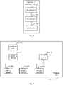
- Fig. 2A is a flow chart of a method for controlling a device according to an example embodiment of the present disclosure. As shown in Fig. 2A , the method may be applied in the smart home device in Fig. 1 , and include the following steps.
- step 201 operation mode configuration information broadcast by a wearable device is received, in which the operation mode configuration information includes a device identification corresponding to the wearable device.
- each of the smart air conditioner and the smart bracelet may be equipped with a communication component.
- the communication component may be a bluetooth component.
- the smart bracelet may broadcast the operation mode configuration information around, and thus within a certain distance range, the smart air conditioner may receive the operation mode configuration information and obtain the device identification corresponding to the smart bracelet by parsing the information.
- the device identification may be identification information capable of identifying the wearable device and carried in the operation mode configuration information, such as a serial number of the wearable device, an ID of the wearable device, a device name, or a MAC (Media Access Control) address of the information, as long as it may identify the wearable device uniquely, which will not be limited herein.
- identification information capable of identifying the wearable device and carried in the operation mode configuration information, such as a serial number of the wearable device, an ID of the wearable device, a device name, or a MAC (Media Access Control) address of the information, as long as it may identify the wearable device uniquely, which will not be limited herein.
- step 202 an operation parameter corresponding to the device identification is obtained.
- the smart home device may determine the operation parameter corresponding to the wearable device according to the device identification carried in the operation mode configuration information, after receiving the operation mode configuration information broadcast by the wearable device.
- the operation parameter corresponding to the device identification is obtained from a preset association relationship table recording correspondence between device identifications and operation parameters of associated wearable devices.
- the association relationship table is established in advance, and correspondence between device identifications and operation parameters of all associated wearable devices is recorded in the association relationship table; the operation mode configuration information sent by the smart bracelet may only carry the device identification, and the smart air conditioner searches the association relationship table according to the device identification so as to obtain the corresponding operation parameter.
- the operation parameter is obtained by using the preset association relationship table, which is easy to implement.
- the operation mode configuration information sent by the wearable device may only carry the device identification, which reduces the resource consumption of the wearable device.
- the association relationship table may be obtained in the following steps: establishing an association relationship with a wearable device; obtaining the device identification and the operation parameter of the associated wearable device, and storing the device identification and the operation parameter in the association relationship table.
- the smart terminal in order to establish the association relationship with the wearable device, the smart terminal may be used to establish the association relationship between the wearable device and the smart home device, or the wearable device and the smart home device may directly establish the association relationship between them.
- the following embodiments will illustrate the two manners for establishing the association relationship respectively.
- the smart terminal is used to establish the association relationship between the wearable device and the smart home device.
- the smart terminal may be a smart phone, a tablet computer, a personal digital assistant (PDA), an e-book reader, a multimedia player, etc.
- PDA personal digital assistant
- client software installed in the smart terminal.
- the client software may be a "Smart Home” application, and the user may obtain corresponding using permission by establishing a binding relationship respectively with the smart home device and the wearable device in the home environment via the application. After the binding relationships are established, the user may use the application for centralized management and control of the smart home device and the wearable device.
- Fig. 2B is a schematic diagram of a smart home application in a smart terminal
- the user establishes the association relationship between a smart air conditioner A and two smart bracelets (smart bracelet A and smart bracelet B).
- the user may associate the air conditioner A with the smart bracelets A and B via the application, and may set corresponding operation parameters (such as temperature, mode and air speed of the air conditioner) for each smart bracelet.
- the smart terminal may send device identifications of the smart bracelets A and B and the operation parameters set for each smart bracelet to the air conditioner A, and the air conditioner A receives and stores the above information in the association relationship table.
- the smart terminal may send both the device identifications and the operation parameters of the smart bracelets to the smart air conditioner, such that the smart bracelet may carry its own device identification in the operation mode configuration information when sending the operation mode configuration information, and the smart air conditioner may search the association relationship table and find the corresponding operation parameter after receiving the operation mode configuration information containing the device identification of the smart bracelet.
- the wearable device may be mated with the smart home device, for example, via a Bluetooth communication component or a NFC (Near Field Communication) component.
- a Bluetooth communication component or a NFC (Near Field Communication) component.
- NFC Near Field Communication
- a mating option set in its remote control may be utilized, such that the smart air conditioner as a master device for mating connection starts establishing the mating connection with the wearable device as a slave device after the user selects the mating option.
- both the smart air conditioner and the wearable device open the Bluetooth function, such that the smart air conditioner searches for the mating information of the wearable device and the wearable device broadcasts its device identification via Bluetooth.
- the smart air conditioner records the device identification after finding the device identification sent by the smart bracelet, thus completing the mating process.
- the user may set the corresponding operation parameter for the bracelet via the remote control and the smart air conditioner may store the device identification and the operation parameter in the association relationship table.
- the smart bracelet may carry its own device identification in the operation mode configuration information when sending the information, and then the smart air conditioner may search the association relationship table and find out the corresponding operation parameter after receiving the operation mode configuration information containing the device identification of the smart bracelet.
- the smart home device may establish the association relationship with the wearable device in advance and store the device identification and the operation parameter of the associated wearable device in the association relationship table, which is easy to implement, and the operation mode configuration information sent by the wearable device only needs to contain the device identification, which reduces the resource consumption of the wearable device.
- the operation parameter corresponding to the device identification is obtained from the operation mode configuration information.
- the operation mode configuration information of the wearable device may carry its own device identification as well as the operation parameter preset by the user.
- the preset operation parameter in the wearable device may be sent by the smart terminal to the wearable device for storage or be sent by the smart home device to the wearable device for storage, after the association relationship is established between the wearable device and the smart home device, as illustrated in the first way.
- the smart home device may directly parse out the device identification and the operation parameter upon receiving the operation mode configuration information, so it is possible to determine the operation parameter corresponding to the wearable device quickly and to improve the working efficiency.
- the step of obtaining the operation parameter corresponding to the device identification includes: obtaining the operation parameter corresponding to the device identification, in response to determining that the wearable device is an associated device according to the device identification.
- the wearable device it is possible to judge whether the wearable device is an associated device according to the device identification; if the wearable device is determined as the associated device, it means that the wearable device has the authority to control the smart home device which further obtains the operation parameter corresponding to the wearable device for operating. If the wearable device is not the associated device, it means that the wearable device has no control authority.
- the wearable device is the associated device according to the device identification, before the operation parameter corresponding to the device identification is obtained, which may improve the security performance of the smart home device.
- the step of obtaining the operation parameter corresponding to the device identification includes: obtaining the operation parameter corresponding to the device identification, in response to determining that the wearable device is located within a preset range.
- the wearable device determines the distance from the wearable device to the smart home device; if the distance is far beyond the preset range, the wearable device may be ignored and only wearable devices in a short distance from the smart home device are considered.
- the preset range may be with a 3-meter radius or with a 5-meter radius, and may be adjusted flexibly according to requirements in practical use, which will not be limited herein.
- a RSSI Receiveived Signal Strength Indication
- the wearable device may be determined within the preset range, in response to determining that the RSSI is higher than a preset strength threshold.
- the RSSI may be obtained when the operation mode configuration information sent by the wearable device is received. If the strength is high, it may be determined that the wearable device is close to the smart home device; if the strength is low, it may be determined that the wearable device is far away from the smart home device. In practical use, the strength threshold may be set flexibly by those skilled in the art according to demands.
- the two implementations for obtaining priority levels and operation parameters corresponding to the device identification may be executed individually and in parallel or may be executed concurrently in practical use.
- the execution sequence may be adjusted. That is, the step of determining whether each wearable device is an associated wearable device may be before or after the step of determining whether each wearable device is located within a preset range.
- the corresponding operation parameter is further obtained after the wearable device is determined to be within a close range, which facilitates flexible control on the operation of the smart home device and thus brings convenience to the user.
- step 203 operation is performed according to the operation parameter.
- the smart home device may operate according to the operation parameter upon obtaining the operation parameter corresponding to the device identification.
- the smart home device may operate according to the corresponding operation parameter automatically as long as the device identification of the wearable device is detected, and thus it is unnecessary for the user to manually adjust the operation mode of the smart device frequently, which brings convenience to the user.
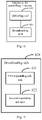
- Fig. 3 is a flow chart of a method for controlling a device according to an example embodiment. As shown in Fig.3 , the method may be applied to the wearable device in Fig. 1 , and include the following steps.
- step 301 a trigger command is detected.
- the user may input the trigger command to a wearable device which the user takes along, and thus the wearable device sends operation mode configuration information to the smart home device after detecting the trigger command.
- step 302 the operation mode configuration information containing a device identification of the wearable device is broadcast, in response to the detected trigger command, in which the operation mode configuration information indicates the smart home device to operate according to the operation parameter corresponding to the device identification.
- the detected trigger command it may include: in response to detecting that the wearable device is tapped for a preset number of times; or in response to detecting that the wearable device is shaken for a preset number of times.
- the trigger command is ascertained to be received, and the preset operation mode configuration information containing the device identification of the wearable device is broadcast, such that the smart home device works according to the operation parameter corresponding to the device identification after receiving the operation mode configuration information.
- the operation mode configuration information may be sent by the wearable device rapidly for controlling smart home device, as longs as the user performs simple operations, which is simple to implement and thus brings convenience to the user.
- the wearable device may send out the operation mode configuration information containing the device identification automatically after receiving the trigger command of the user, and indicate the smart home device to operate according to the operation parameter corresponding to the device identification via the operation mode configuration information. In this embodiment, it is unnecessary for the user to manually adjust the operation mode of the smart device frequently, which brings convenience to the user.
- the operation mode configuration information further includes the operation parameter corresponding to the device identification.
- the operation mode configuration information of the wearable device may carry its own device identification and the preset operation parameter.
- the wearable device may establish the association relationship with the smart home device in advance, and then receive the operation parameter sent by the smart terminal or sent by the smart home device for storage after the association relationship is established.
- the smart home device may directly parse out the device identification and the operation parameter upon receiving the operation mode configuration information, and thus it is possible to determine the operation parameter corresponding to the wearable device quickly and to improve the working efficiency.
- Fig. 4 is a block diagram of an apparatus for controlling a device according to an example embodiment of the present disclosure. As shown in Fig. 4 , the apparatus includes a receiving unit 410, an obtaining unit 420 and an operating unit 430.
- the receiving unit 410 is configured to receive operation mode configuration information broadcast by a wearable device, the operation mode configuration information having a device identification corresponding to the wearable device.
- the obtaining unit 420 is configured to obtain an operation parameter corresponding to the device identification received by the receiving unit 410.
- the operating unit 430 is configured to operate according to the operation parameter obtained by the obtaining unit 420.
- the wearable device sends out the operation mode configuration information containing the device identification, such that the smart home device may obtain the operation parameter corresponding to the device identification and operate according to the operation parameter.
- the smart device may operate automatically according to the corresponding operation parameter as long as the device identification of the wearable device is detected, and thus the user does not need to manually adjust the operation mode of the smart device frequently, which brings convenience to the user.
- Fig. 5 is a block diagram of another apparatus for controlling a device according to an example embodiment of the present disclosure.
- the obtaining unit 420 includes a first obtaining sub-unit 421 configured to obtain the operation parameter corresponding to the device identification received by the receiving unit 410 from a preset association relationship table recording correspondence between device identifications and operation parameters of associated wearable devices.
- the operation parameter is obtained from the preset association relationship table, which is easy to implement, and the operation mode configuration information sent by the wearable device only needs to contain the device identification, which reduces the resource consumption of the wearable device.
- the obtaining unit 420 further includes an establishing sub-unit 422 and a storing sub-unit 423.
- the establishing sub-unit 422 is configured to establish an association relationship with a wearable device.
- the storing sub-unit 423 is configured to obtain the device identification and the operation parameter of the associated wearable device in the establishing sub-unit 422, and store the device identification and the operation parameter in the association relationship table.
- the smart home device in the present disclosure may establish the association relationship with the wearable device in advance and store the device identification and the operation parameter of the associated wearable device in the association relationship table, which is easy to implement, and the operation mode configuration information sent by the wearable device only needs to carry the device identification, which reduces the resource consumption of the wearable device.
- the obtaining unit 420 further includes a second obtaining sub-unit 424 configured to obtain the operation parameter corresponding to the device identification from the operation mode configuration information received by the receiving unit 410.
- the smart home device in the present disclosure may directly parse out the device identification and the operation parameter upon receiving the operation mode configuration information, so it is possible to determine the operation parameter corresponding to the wearable device quickly and to improve the working efficiency.
- the obtaining unit 420 further includes a third obtaining sub-unit 425 configured to obtain the operation parameter corresponding to the device identification, in response to determining that the wearable device is an associated device according to the device identification received by the receiving unit 410.
- the wearable device is the associated device according to the device identification, before the operation parameter corresponding to the device identification is obtained, which may improve the security performance of the smart home device.
- the obtaining unit 420 further includes a fourth obtaining sub-unit 426 configured to obtain the operation parameter corresponding to the device identification received by the receiving unit 410, in response to determining that the wearable device is located within a preset range.
- the corresponding operation parameter is further obtained after it is determined that the wearable device is within a close range, which facilitates flexible control on the operation of the smart home device and thus brings convenience to the user.
- Fig. 6 is a block diagram of another apparatus for controlling a device according to an example embodiment of the present disclosure. As shown in Fig. 6 , the apparatus includes a detecting unit 610 and a broadcasting unit 620.
- the detecting unit 610 is configured to detect a trigger command.
- the broadcasting unit 620 is configured to broadcast operation mode configuration information having a device identification of a wearable device, in response to the trigger command detected by the detecting unit 610, in which the operation mode configuration information indicates an smart home device to operate according to an operation parameter corresponding to the device identification.
- the wearable device in the present disclosure may send out the operation mode configuration information containing the device identification automatically upon receiving the trigger command from the user; the operation mode configuration information indicates the smart home device to operate according to the operation parameter corresponding to the device identification.
- the operation mode configuration information indicates the smart home device to operate according to the operation parameter corresponding to the device identification.
- Fig. 7 is a block diagram of another apparatus for controlling a device according to an example embodiment of the present disclosure.
- the broadcasting unit 620 includes any one of a first responding sub-unit 621 and a second responding sub-unit 622. For the sake of illustration, both the above two sub-units are shown in Fig. 7 .
- the first responding sub-unit 621 is configured to respond to detecting that the wearable device is tapped for a preset number of times.
- the second responding sub-unit 622 is configured to respond to detecting that the wearable device is shaken for a preset number of times.
- the operation mode configuration information may be sent by the wearable device rapidly for controlling the home device, as long as the user performs simple operations, which is simple to implement and thus brings convenience to the user.
- the operation mode configuration information further includes the operation parameter corresponding to the device identification.
- the smart home device may directly parse out the device identification and the operation parameter upon receiving the operation mode configuration information, and thus it is possible to determine the operation parameter corresponding to the wearable device quickly and to improve the working efficiency.
- the present disclosure further provides an apparatus.
- the apparatus includes a processor, and a memory configured to store instructions executable by the processor, in which the processor is configured to: receive operation mode configuration information broadcast by a wearable device, the operation mode configuration information having a device identification corresponding to the wearable device; obtain an operation parameter corresponding to the device identification; and operate according to the operation parameter.
- the present disclosure further provides an apparatus.
- the apparatus includes a processor, and a memory configured to store instructions executable by the processor, in which the processor is configured to: detect a trigger command; and broadcast operation mode configuration information having a device identification of a wearable device, in response to the detected trigger command, in which the operation mode configuration information indicates an smart home device to operate according to an operation parameter corresponding to the device identification.
- the present disclosure further provides a system for controlling a device.
- the system includes: an smart home device configured to receive operation mode configuration information broadcast by a wearable device, the operation mode configuration information having a device identification corresponding to the wearable device, to obtain an operation parameter corresponding to the device identification, and to operate according to the operation parameter; and the wearable device configured to detect a trigger command, and to broadcast the operation mode configuration information in response to the detected trigger command.
- the apparatus embodiment is substantially corresponding to the method embodiment, so relevant part of illustration of the method embodiment may be referred to.
- the apparatus embodiment described above is only exemplary, in which the units described as separate components may be or may not be physically separate; the component as the displaying unit may be or not be a physical unit, i.e. may be located at a position or be distributed at many network elements. It is possible to select part of or all of the modules to realize the objective of the present disclosure, which may be understood and implemented by those skilled in the art without paying more creative effort.
- Fig. 8 is a block diagram of an apparatus 800 for controlling a device according to an example embodiment of the present disclosure.
- the apparatus 800 may be a mobile phone, a computer, a digital broadcasting terminal, message sending and receiving equipment, a game controller, a tablet device, a medical device, fitness equipment and a personal digital assistant.
- the apparatus 800 may include one or more of the following components: a processing component 802, a memory 804, a power component 806, a multimedia component 808, an audio component 810, an input/output (I/O) interface 812, a sensor component 814, and a communication component 816.
- a processing component 802 a memory 804, a power component 806, a multimedia component 808, an audio component 810, an input/output (I/O) interface 812, a sensor component 814, and a communication component 816.
- the processing component 802 typically controls overall operations of the apparatus 800, such as the operations associated with display, telephone calls, data communications, camera operations, and recording operations.
- the processing component 802 may include one or more processors 820 to execute instructions to perform all or part of the steps in the above described methods.
- the processing component 802 may include one or more modules which facilitate the interaction between the processing component 802 and other components.
- the processing component 802 may include a multimedia module to facilitate the interaction between the multimedia component 808 and the processing component 802.
- the memory 804 is configured to store various types of data to support the operation of the apparatus 800. Examples of such data include instructions for any applications or methods operated on the apparatus 800, contact data, phonebook data, messages, pictures, video, etc.
- the memory 804 may be implemented using any type of volatile or non-volatile memory devices, or a combination thereof, such as a static random access memory (SRAM), an electrically erasable programmable read-only memory (EEPROM), an erasable programmable read-only memory (EPROM), a programmable read-only memory (PROM), a read-only memory (ROM), a magnetic memory, a flash memory, a magnetic or optical disk.
- SRAM static random access memory
- EEPROM electrically erasable programmable read-only memory
- EPROM erasable programmable read-only memory
- PROM programmable read-only memory
- ROM read-only memory
- magnetic memory a magnetic memory
- flash memory a flash memory
- magnetic or optical disk a magnetic or optical
- the power component 806 provides power to various components of the apparatus 800.
- the power component 806 may include a power management system, one or more power sources, and any other components associated with the generation, management, and distribution of power in the apparatus 800.
- the multimedia component 808 includes a screen providing an output interface between the apparatus 800 and the user.
- the screen may include a liquid crystal display (LCD) and a touch panel (TP). If the screen includes the touch panel, the screen may be implemented as a touch screen to receive input signals from the user.
- the touch panel includes one or more touch sensors to sense touches, swipes, and gestures on the touch panel. The touch sensors may not only sense a boundary of a touch or swipe action, but also sense a period of time and a pressure associated with the touch or swipe action.
- the multimedia component 808 includes a front camera and/or a rear camera. The front camera and the rear camera may receive an external multimedia datum while the apparatus 800 is in an operation mode, such as a photographing mode or a video mode. Each of the front camera and the rear camera may be a fixed optical lens system or have focus and optical zoom capability.
- the audio component 810 is configured to output and/or input audio signals.
- the audio component 810 includes a microphone ("MIC") configured to receive an external audio signal when the apparatus 800 is in an operation mode, such as a call mode, a recording mode, and a voice recognition mode.
- the received audio signal may be further stored in the memory 804 or transmitted via the communication component 816.
- the audio component 810 further includes a speaker to output audio signals.
- the I/O interface 812 provides an interface between the processing component 802 and peripheral interface modules, such as a keyboard, a click wheel, buttons, and the like.
- the buttons may include, but are not limited to, a home button, a volume button, a starting button, and a locking button.
- the sensor component 814 includes one or more sensors to provide status assessments of various aspects of the apparatus 800. For instance, the sensor component 814 may detect an open/closed status of the apparatus 800, relative positioning of components, e.g., the display and the keypad, of the apparatus 800, a change in position of the apparatus 800 or a component of the apparatus 800, a presence or absence of user contact with the apparatus 800, an orientation or an acceleration/deceleration of the apparatus 800, and a change in temperature of the apparatus 800.
- the sensor component 814 may include a proximity sensor configured to detect the presence of nearby objects without any physical contact.
- the sensor component 814 may also include a light sensor, such as a CMOS or CCD image sensor, for use in imaging applications.
- the sensor component 814 may also include an accelerometer sensor, a gyroscope sensor, a magnetic sensor, a pressure sensor, or a temperature sensor.
- the communication component 816 is configured to facilitate communication, wired or wirelessly, between the apparatus 800 and other devices.
- the apparatus 800 can access a wireless network based on a communication standard, such as WiFi, 2G, or 3G, or a combination thereof.
- the communication component 816 receives a broadcast signal or broadcast associated information from an external broadcast management system via a broadcast channel.
- the communication component 816 further includes a near field communication (NFC) module to facilitate short-range communications.
- the NFC module may be implemented based on a radio frequency identification (RFID) technology, an infrared data association (IrDA) technology, an ultra-wideband (UWB) technology, a Bluetooth (BT) technology, and other technologies.
- RFID radio frequency identification
- IrDA infrared data association
- UWB ultra-wideband
- BT Bluetooth
- the apparatus 800 may be implemented with one or more application specific integrated circuits (ASICs), digital signal processors (DSPs), digital signal processing devices (DSPDs), programmable logic devices (PLDs), field programmable gate arrays (FPGAs), controllers, micro-controllers, microprocessors, or other electronic components, for performing the above described methods.
- ASICs application specific integrated circuits
- DSPs digital signal processors
- DSPDs digital signal processing devices
- PLDs programmable logic devices
- FPGAs field programmable gate arrays
- controllers micro-controllers, microprocessors, or other electronic components, for performing the above described methods.
- non-transitory computer-readable storage medium including instructions, such as included in the memory 804, executable by the processor 820 in the apparatus 800, for performing the above-described methods.
- the non-transitory computer-readable storage medium may be a ROM, a RAM, a CD-ROM, a magnetic tape, a floppy disc, an optical data storage device, and the like.
- a non-transitory computer-readable storage medium has stored therein instructions that, when executed by a processor of a mobile terminal, cause the mobile terminal to perform a method for controlling a device.
Landscapes
- Engineering & Computer Science (AREA)
- Automation & Control Theory (AREA)
- Computer Networks & Wireless Communication (AREA)
- Signal Processing (AREA)
- Human Computer Interaction (AREA)
- Physics & Mathematics (AREA)
- General Physics & Mathematics (AREA)
- Selective Calling Equipment (AREA)
- User Interface Of Digital Computer (AREA)
- Air Conditioning Control Device (AREA)
- Telephone Function (AREA)
- Management, Administration, Business Operations System, And Electronic Commerce (AREA)
Claims (11)
- Verfahren zum Steuern eines Smart-Home-Geräts bzw. intelligenten Heimgeräts, umfassend:Empfangen (201) von Betriebsmodus-Konfigurationsinformationen, die von einem tragbaren Gerät gesendet werden, wobei die Betriebsmodus-Konfigurationsinformationen eine Geräteidentifikation umfassen, die dem tragbaren Gerät entspricht;Erhalten (202) eines Betriebsparameters, der der Geräteidentifikation entspricht, umfassend: Erhalten des Betriebsparameters, der der Geräteidentifikation entspricht, aus einer voreingestellten Zuordnungsbeziehungstabelle, die die Entsprechung zwischen Geräteidentifikationen und Betriebsparametern zugeordneter tragbarer Geräte aufzeichnet; undBetreiben (203) des Smart-Home-Geräts entsprechend den Betriebsparametern;wobei das Erhalten (202) eines Betriebsparameters, der der Geräteidentifikation entspricht, umfasst:
Erhalten des Betriebsparameters, der der Geräteidentifikation entspricht, als Reaktion auf die Feststellung, dass sich das tragbare Gerät innerhalb eines voreingestellten Bereichs befindet. - Verfahren nach Anspruch 1, ferner umfassend:Herstellen einer Zuordnungsbeziehung mit einem tragbaren Gerät;Erhalten der Geräteidentifikation und des Betriebsparameters des zugehörigen tragbaren Geräts, und Speichern der Geräteidentifikation und des Betriebsparameters in der Zuordnungsbeziehungstabelle.
- Verfahren nach einem der vorhergehenden Ansprüche, wobei das Erhalten (202) eines Betriebsparameters, der der Geräteidentifikation entspricht, umfasst:
Erhalten des Betriebsparameters, der der Geräteidentifikation entspricht, aus der Betriebsmodus-Konfigurationsinformation. - Verfahren nach einem der vorhergehenden Ansprüche, wobei das Erhalten (202) eines Betriebsparameters, der der Geräteidentifikation entspricht, umfasst:
Erhalten des Betriebsparameters, der der Geräteidentifikation entspricht, als Reaktion auf die Feststellung, dass das tragbare Gerät ein zugehöriges Gerät gemäß der Geräteidentifikation ist. - Vorrichtung zum Steuern eines Smart-Home-Geräts, die Folgendes umfasst:eine Empfangseinheit (410), die so konfiguriert ist, dass sie von einem tragbaren Gerät gesendete Betriebsmodus-Konfigurationsinformationen empfängt, wobei die Betriebsmodus-Konfigurationsinformationen eine dem tragbaren Gerät entsprechende Gerätekennung umfassen;eine Erhaltungseinheit (420), die konfiguriert ist, um einen Betriebsparameter zu erhalten, der der von der Empfangseinheit (410) empfangenen Geräteidentifikation entspricht; undeine Bedieneinheit (430), die so konfiguriert ist, dass sie das Smart-Home-Gerät entsprechend den von der Erfassungseinheit (420) erhaltenen Betriebsparametern bedient,wobei die Erhaltungseinheit (420) umfasst:eine erste Erhaltungssuntereinheit (421), die so konfiguriert ist, dass sie den Betriebsparameter, der der von der Empfangseinheit (410) empfangenen Geräteidentifikation entspricht, aus einer voreingestellten Zuordnungsbeziehungstabelle erhält, die die Entsprechung zwischen Geräteidentifikationen und Betriebsparametern zugeordneter tragbarer Geräte aufzeichnet, undeine vierte Erhaltungsuntereinheit (426), die so konfiguriert ist, dass sie den Betriebsparameter, der der von der Empfangseinheit (410) empfangenen Geräteidentifikation entspricht, in Reaktion auf die Feststellung, dass sich das tragbare Gerät innerhalb eines voreingestellten Bereichs befindet, erfasst.
- Vorrichtung nach Anspruch 5, wobei die Erhaltungseinheit (420) ferner umfasst:eine Aufbau-Untereinheit (422), die so konfiguriert ist, dass sie eine Zuordnungsbeziehung mit einer tragbaren Vorrichtung herstellt; undeine Speicheruntereinheit (423), die so konfiguriert ist, dass sie die Geräteidentifikation und den Betriebsparameter des zugehörigen tragbaren Geräts erhält und die Geräteidentifikation und den Betriebsparameter in der Zuordnungsbeziehungstabelle speichert.
- Vorrichtung nach Anspruch 5 oder 6, wobei die Erhaltungseinheit (420) umfasst:
eine zweite Erhaltungsuntereinheit (424), die so konfiguriert ist, dass sie den Betriebsparameter, der der Geräteidentifikation entspricht, aus den von der Empfangseinheit (410) empfangenen Betriebsmodus-Konfigurationsinformationen erhält. - Vorrichtung nach einem der Ansprüche 5 bis 7, wobei die Erhaltungseinheit (420) umfasst:
eine dritte Erhaltungsuntereinheit (425), die so konfiguriert ist, dass sie den Betriebsparameter, der der Geräteidentifikation entspricht, in Reaktion auf die Bestimmung, dass das tragbare Gerät ein zugehöriges Gerät ist, gemäß der von der Empfangseinheit (410) empfangenen Geräteidentifikation erhält. - System zur Steuerung eines Smart-Home-Geräts, das Folgendes umfasst:das Smart-Home-Gerät, das so konfiguriert ist, dass es Betriebsmodus-Konfigurationsinformationen empfängt, die von einem tragbaren Gerät gesendet werden, wobei die Betriebsmodus-Konfigurationsinformationen eine Geräteidentifikation umfassen, die dem tragbaren Gerät entspricht, um einen Betriebsparameter zu erhalten, der der Geräteidentifikation entspricht, als Reaktion auf die Feststellung, dass sich das tragbare Gerät innerhalb eines voreingestellten Bereichs befindet, und um gemäß dem Betriebsparameter zu arbeiten, wobei der Betriebsparameter aus einer voreingestellten Zuordnungsbeziehungstabelle erhalten wird, die die Entsprechung zwischen Geräteidentifikationen und Betriebsparametern von zugeordneten tragbaren Geräten aufzeichnet; unddas tragbare Gerät, das so konfiguriert ist, dass es einen Auslösebefehl erkennt und die Betriebsmodus-Konfigurationsinformationen als Reaktion auf den erkannten Auslösebefehl sendet.
- Computerprogramm mit Anweisungen zum Ausführen von Schritten eines Verfahrens zum Steuern eines Smart-Home-Geräts nach einem der Ansprüche 1 bis 4, wenn das Programm von einem Computer ausgeführt wird.
- Speichermedium, das von einem Computer gelesen werden kann und auf dem ein Computerprogramm nach Anspruch 10 gespeichert ist.
Applications Claiming Priority (1)
| Application Number | Priority Date | Filing Date | Title |
|---|---|---|---|
| CN201510491263.1A CN105182815A (zh) | 2015-08-11 | 2015-08-11 | 设备控制方法及装置 |
Publications (2)
| Publication Number | Publication Date |
|---|---|
| EP3131235A1 EP3131235A1 (de) | 2017-02-15 |
| EP3131235B1 true EP3131235B1 (de) | 2022-10-05 |
Family
ID=54904961
Family Applications (1)
| Application Number | Title | Priority Date | Filing Date |
|---|---|---|---|
| EP16166113.7A Active EP3131235B1 (de) | 2015-08-11 | 2016-04-20 | Verfahren und vorrichtung zur steuerung einer vorrichtung |
Country Status (7)
| Country | Link |
|---|---|
| US (1) | US20170048078A1 (de) |
| EP (1) | EP3131235B1 (de) |
| JP (1) | JP6360565B2 (de) |
| CN (1) | CN105182815A (de) |
| MX (1) | MX2017005840A (de) |
| RU (1) | RU2658194C2 (de) |
| WO (1) | WO2017024740A1 (de) |
Families Citing this family (24)
| Publication number | Priority date | Publication date | Assignee | Title |
|---|---|---|---|---|
| CN105182815A (zh) * | 2015-08-11 | 2015-12-23 | 小米科技有限责任公司 | 设备控制方法及装置 |
| CN105187282B (zh) * | 2015-08-13 | 2018-10-26 | 小米科技有限责任公司 | 智能家居设备的控制方法、装置、系统及设备 |
| CN105928722B (zh) * | 2016-04-18 | 2020-04-03 | 合肥美的暖通设备有限公司 | 空调器性能检测系统和方法 |
| CN106506592A (zh) * | 2016-10-01 | 2017-03-15 | 杭州鸿雁智能科技有限公司 | 一种基于Wi‑Fi的点对点控制的方法与系统 |
| CN106534258B (zh) * | 2016-10-01 | 2020-02-04 | 杭州鸿雁智能科技有限公司 | 一种Wi-Fi关联触发的方法及系统 |
| CN109769231A (zh) * | 2017-11-09 | 2019-05-17 | 北京君正集成电路股份有限公司 | 蓝牙配对连接方法和装置 |
| CN109981708A (zh) * | 2017-12-27 | 2019-07-05 | 浙江绍兴苏泊尔生活电器有限公司 | 联网设备控制方法及装置 |
| US11057238B2 (en) * | 2018-01-08 | 2021-07-06 | Brilliant Home Technology, Inc. | Automatic scene creation using home device control |
| US10985972B2 (en) | 2018-07-20 | 2021-04-20 | Brilliant Home Technoloy, Inc. | Distributed system of home device controllers |
| CN109361727B (zh) * | 2018-08-30 | 2021-12-07 | Oppo广东移动通信有限公司 | 信息共享方法、装置、存储介质及穿戴式设备 |
| CN110749045B (zh) * | 2019-09-04 | 2022-03-18 | 安徽博微长安电子有限公司 | 粮库用空调集中式控制系统 |
| CN110780598B (zh) * | 2019-10-24 | 2023-05-16 | 深圳传音控股股份有限公司 | 一种智能设备控制方法、装置、电子设备及可读存储介质 |
| CN113037799A (zh) * | 2019-12-25 | 2021-06-25 | 佛山市云米电器科技有限公司 | 饮水设备的控制方法、云端服务器、控制系统和存储介质 |
| WO2021138698A1 (en) | 2020-01-05 | 2021-07-08 | Brilliant Home Technology, Inc. | Touch-based control device |
| US11528028B2 (en) | 2020-01-05 | 2022-12-13 | Brilliant Home Technology, Inc. | Touch-based control device to detect touch input without blind spots |
| KR102951768B1 (ko) * | 2020-05-27 | 2026-04-14 | 삼성전자주식회사 | 서버 및 그의 제어 방법 |
| CN112423240B (zh) * | 2020-11-11 | 2022-06-28 | 珠海优特智厨科技有限公司 | 锅具与灶具的绑定方法、装置及计算机设备 |
| CN112880141A (zh) * | 2021-01-27 | 2021-06-01 | 青岛海尔空调器有限总公司 | 空调器的控制方法及空调器控制系统 |
| JP7591954B2 (ja) * | 2021-03-15 | 2024-11-29 | 大阪瓦斯株式会社 | リモコン |
| CN115437271A (zh) * | 2021-06-02 | 2022-12-06 | 云米互联科技(广东)有限公司 | 基于虚拟地图的智能设备控制方法及装置 |
| CN113917848A (zh) * | 2021-11-15 | 2022-01-11 | 珠海格力电器股份有限公司 | 家居设备控制方法及装置 |
| CN114221831B (zh) * | 2021-12-20 | 2022-10-11 | 珠海格力电器股份有限公司 | 家居设备控制方法、装置、电子设备及存储介质 |
| CN117515787A (zh) * | 2022-07-29 | 2024-02-06 | 广东美的制冷设备有限公司 | 空气调节设备、点控装置、配对方法、控制系统及介质 |
| CN118041539A (zh) * | 2022-11-11 | 2024-05-14 | 北京京东方技术开发有限公司 | 一种权限控制方法、智能车辆及智能家居设备 |
Citations (2)
| Publication number | Priority date | Publication date | Assignee | Title |
|---|---|---|---|---|
| US20130265229A1 (en) * | 2012-04-09 | 2013-10-10 | Qualcomm Incorporated | Control of remote device based on gestures |
| CN104301758A (zh) * | 2014-10-10 | 2015-01-21 | 安徽华米信息科技有限公司 | 一种推送视频的方法、装置及系统 |
Family Cites Families (27)
| Publication number | Priority date | Publication date | Assignee | Title |
|---|---|---|---|---|
| JPH01108602A (ja) * | 1987-10-21 | 1989-04-25 | Matsushita Electric Ind Co Ltd | シーケンス制御装置 |
| JPH0618080A (ja) * | 1992-07-02 | 1994-01-25 | Daikin Ind Ltd | 空気調和機用ワイヤレスリモコン装置 |
| US6523696B1 (en) * | 1996-10-15 | 2003-02-25 | Kabushiki Kaisha Toshiba | Communication control device for realizing uniform service providing environment |
| US6879806B2 (en) * | 2001-06-01 | 2005-04-12 | Zensys A/S | System and a method for building routing tables and for routing signals in an automation system |
| JP4516042B2 (ja) * | 2006-03-27 | 2010-08-04 | 株式会社東芝 | 機器操作装置および機器操作方法 |
| US8125448B2 (en) * | 2006-10-06 | 2012-02-28 | Microsoft Corporation | Wearable computer pointing device |
| WO2009004772A1 (ja) * | 2007-07-05 | 2009-01-08 | Panasonic Corporation | ロボットアームの制御装置及び制御方法、ロボット、及び制御プログラム |
| JP5543835B2 (ja) * | 2010-04-23 | 2014-07-09 | パナソニック株式会社 | 機器制御システム |
| JP5495060B2 (ja) * | 2010-08-05 | 2014-05-21 | 清水建設株式会社 | 環境調整制御装置 |
| US8908894B2 (en) * | 2011-12-01 | 2014-12-09 | At&T Intellectual Property I, L.P. | Devices and methods for transferring data through a human body |
| CN202870490U (zh) * | 2012-08-14 | 2013-04-10 | 徐臻毅 | 加药控制装置 |
| RU130098U1 (ru) * | 2012-09-10 | 2013-07-10 | Общество с ограниченной ответственностью "Браво Моторс" | Система "умный дом" с интеллектуальным адаптивным входом/выходом |
| JP2014086944A (ja) * | 2012-10-25 | 2014-05-12 | Sharp Corp | 空気調和機、および空気調和システム |
| KR20140109020A (ko) * | 2013-03-05 | 2014-09-15 | 한국전자통신연구원 | 스마트 가전기기의 제어를 위한 디바이스 정보 구축 장치 및 그 방법 |
| US9329695B2 (en) * | 2013-10-04 | 2016-05-03 | Panasonic Intellectual Property Corporation Of America | Wearable terminal and method for controlling the same |
| CN103566710B (zh) * | 2013-11-08 | 2015-10-21 | 中石化南京工程有限公司 | 一种用于变压吸附装置的多塔控制方法 |
| JP6231362B2 (ja) * | 2013-11-25 | 2017-11-15 | アズビル株式会社 | プラント監視サーバーおよびプラント監視方法 |
| EP4071581B1 (de) * | 2013-11-29 | 2025-10-08 | Ouraring Inc. | Am körper tragbare berechnungsvorrichtung |
| JP6352629B2 (ja) * | 2013-12-17 | 2018-07-04 | 株式会社東芝 | 制御方法、情報処理装置およびプログラム |
| US20150187388A1 (en) * | 2013-12-26 | 2015-07-02 | Nathan R. Andrysco | Intelligent recording in electronic devices |
| CN104156064B (zh) * | 2014-07-18 | 2017-07-28 | 小米科技有限责任公司 | 互动目标控制方法及装置 |
| CN104121663A (zh) * | 2014-07-24 | 2014-10-29 | 海信集团有限公司 | 一种控制智能空调的方法及设备 |
| CN104376039A (zh) * | 2014-10-10 | 2015-02-25 | 安徽华米信息科技有限公司 | 一种推送网络内容的方法、装置及系统 |
| CN104570746B (zh) * | 2014-11-24 | 2017-09-29 | 青岛歌尔声学科技有限公司 | 一种智能家居控制系统、方法和一种智能家居 |
| JP2016217583A (ja) * | 2015-05-18 | 2016-12-22 | 株式会社東芝 | 空調制御装置 |
| CN105182815A (zh) * | 2015-08-11 | 2015-12-23 | 小米科技有限责任公司 | 设备控制方法及装置 |
| CN105182766A (zh) * | 2015-08-12 | 2015-12-23 | 小米科技有限责任公司 | 设备控制方法及装置 |
-
2015
- 2015-08-11 CN CN201510491263.1A patent/CN105182815A/zh active Pending
- 2015-12-30 RU RU2016138417A patent/RU2658194C2/ru active
- 2015-12-30 WO PCT/CN2015/099686 patent/WO2017024740A1/zh not_active Ceased
- 2015-12-30 MX MX2017005840A patent/MX2017005840A/es unknown
- 2015-12-30 JP JP2016564322A patent/JP6360565B2/ja active Active
-
2016
- 2016-04-20 EP EP16166113.7A patent/EP3131235B1/de active Active
- 2016-07-22 US US15/216,706 patent/US20170048078A1/en not_active Abandoned
Patent Citations (3)
| Publication number | Priority date | Publication date | Assignee | Title |
|---|---|---|---|---|
| US20130265229A1 (en) * | 2012-04-09 | 2013-10-10 | Qualcomm Incorporated | Control of remote device based on gestures |
| CN104301758A (zh) * | 2014-10-10 | 2015-01-21 | 安徽华米信息科技有限公司 | 一种推送视频的方法、装置及系统 |
| US20160105722A1 (en) * | 2014-10-10 | 2016-04-14 | Anhui Huami Information Technology Co., Ltd. | Video pushing method, apparatus, and system |
Also Published As
| Publication number | Publication date |
|---|---|
| US20170048078A1 (en) | 2017-02-16 |
| EP3131235A1 (de) | 2017-02-15 |
| RU2658194C2 (ru) | 2018-06-19 |
| JP6360565B2 (ja) | 2018-07-18 |
| CN105182815A (zh) | 2015-12-23 |
| JP2017530321A (ja) | 2017-10-12 |
| RU2016138417A3 (de) | 2018-03-29 |
| MX2017005840A (es) | 2017-06-27 |
| RU2016138417A (ru) | 2018-03-29 |
| WO2017024740A1 (zh) | 2017-02-16 |
Similar Documents
| Publication | Publication Date | Title |
|---|---|---|
| EP3131235A1 (de) | Verfahren und vorrichtung zur steuerung einer vorrichtung | |
| EP3163885B1 (de) | Verfahren und vorrichtung zur steuerung einer elektronischen vorrichtung | |
| CN111343058B (zh) | 设备控制方法、装置、控制设备及存储介质 | |
| EP3145125B1 (de) | Verfahren und vorrichtung zur steuerung von vorrichtungen | |
| EP3131258B1 (de) | Steuerungsverfahren für intelligente haushaltsgeräte und zugehörige vorrichtung | |
| CN105182766A (zh) | 设备控制方法及装置 | |
| EP3136793B1 (de) | Verfahren und vorrichtung zum aufwecken einer elektronischen vorrichtung | |
| KR101842379B1 (ko) | 지능형 전기 장치의 작동 방법 및 작동 디바이스 | |
| EP3174251B1 (de) | Verfahren und vorrichtung zur identifizierung des typs einer elektronischen vorrichtung an einer intelligenten buchse | |
| EP3148161B1 (de) | Nachrichtenübertragungsverfahren, nachrichtenempfangsverfahren und -vorrichtung, computerprogramm und aufzeichnungsmedium | |
| US20170125035A1 (en) | Controlling smart device by voice | |
| US20170091551A1 (en) | Method and apparatus for controlling electronic device | |
| US20170243475A1 (en) | Methods and devices for binding a remote control | |
| EP3232715A1 (de) | Verfahren und vorrichtung für zugriff auf einen drahtlosen zugriffspunkt | |
| EP3119039A1 (de) | Verfahren und vorrichtung zur steuerung einer intelligenten vorrichtung | |
| EP3128774A1 (de) | Verfahren, vorrichtungen und system zum zugriff auf ein netzwerk | |
| EP3171293A1 (de) | Verfahren und vorrichtung zur steuerung intelligenter ausrüstung | |
| EP3322227B1 (de) | Verfahren und vorrichtungen zur steuerung einer drahtlosen verbindung, computerprogramm und aufzeichnungsmedium | |
| EP3125152A1 (de) | Verfahren und vorrichtung zum sammeln von klängen gemäss überwachungsbildern | |
| CN104834545A (zh) | 启动终端的方法及装置 | |
| US20170019482A1 (en) | Method and apparatus for downloading control program | |
| US20170180148A1 (en) | Method, device and system for intelligent household appliance to access multiple servers | |
| EP3291489B1 (de) | Verfahren und vorrichtung zur vorrichtungsidentifizierung | |
| EP3182393B1 (de) | Verfahren, vorrichtung und system zur auslösung einer bindung einer fernsteuerung | |
| CN105610608A (zh) | 智能插座工作状态提醒的方法及装置 |
Legal Events
| Date | Code | Title | Description |
|---|---|---|---|
| PUAI | Public reference made under article 153(3) epc to a published international application that has entered the european phase |
Free format text: ORIGINAL CODE: 0009012 |
|
| STAA | Information on the status of an ep patent application or granted ep patent |
Free format text: STATUS: REQUEST FOR EXAMINATION WAS MADE |
|
| 17P | Request for examination filed |
Effective date: 20160420 |
|
| AK | Designated contracting states |
Kind code of ref document: A1 Designated state(s): AL AT BE BG CH CY CZ DE DK EE ES FI FR GB GR HR HU IE IS IT LI LT LU LV MC MK MT NL NO PL PT RO RS SE SI SK SM TR |
|
| AX | Request for extension of the european patent |
Extension state: BA ME |
|
| STAA | Information on the status of an ep patent application or granted ep patent |
Free format text: STATUS: EXAMINATION IS IN PROGRESS |
|
| 17Q | First examination report despatched |
Effective date: 20190423 |
|
| REG | Reference to a national code |
Ref country code: DE Ref legal event code: R079 Ref document number: 602016075400 Country of ref document: DE Free format text: PREVIOUS MAIN CLASS: H04L0012280000 Ipc: H04W0004800000 |
|
| RIC1 | Information provided on ipc code assigned before grant |
Ipc: H04W 4/80 20180101AFI20200519BHEP Ipc: H04L 12/28 20060101ALI20200519BHEP |
|
| GRAP | Despatch of communication of intention to grant a patent |
Free format text: ORIGINAL CODE: EPIDOSNIGR1 |
|
| STAA | Information on the status of an ep patent application or granted ep patent |
Free format text: STATUS: GRANT OF PATENT IS INTENDED |
|
| INTG | Intention to grant announced |
Effective date: 20220426 |
|
| GRAS | Grant fee paid |
Free format text: ORIGINAL CODE: EPIDOSNIGR3 |
|
| GRAA | (expected) grant |
Free format text: ORIGINAL CODE: 0009210 |
|
| STAA | Information on the status of an ep patent application or granted ep patent |
Free format text: STATUS: THE PATENT HAS BEEN GRANTED |
|
| AK | Designated contracting states |
Kind code of ref document: B1 Designated state(s): AL AT BE BG CH CY CZ DE DK EE ES FI FR GB GR HR HU IE IS IT LI LT LU LV MC MK MT NL NO PL PT RO RS SE SI SK SM TR |
|
| REG | Reference to a national code |
Ref country code: GB Ref legal event code: FG4D |
|
| REG | Reference to a national code |
Ref country code: CH Ref legal event code: EP |
|
| REG | Reference to a national code |
Ref country code: AT Ref legal event code: REF Ref document number: 1523517 Country of ref document: AT Kind code of ref document: T Effective date: 20221015 |
|
| REG | Reference to a national code |
Ref country code: DE Ref legal event code: R096 Ref document number: 602016075400 Country of ref document: DE |
|
| REG | Reference to a national code |
Ref country code: IE Ref legal event code: FG4D |
|
| REG | Reference to a national code |
Ref country code: LT Ref legal event code: MG9D |
|
| REG | Reference to a national code |
Ref country code: NL Ref legal event code: MP Effective date: 20221005 |
|
| REG | Reference to a national code |
Ref country code: AT Ref legal event code: MK05 Ref document number: 1523517 Country of ref document: AT Kind code of ref document: T Effective date: 20221005 |
|
| PG25 | Lapsed in a contracting state [announced via postgrant information from national office to epo] |
Ref country code: NL Free format text: LAPSE BECAUSE OF FAILURE TO SUBMIT A TRANSLATION OF THE DESCRIPTION OR TO PAY THE FEE WITHIN THE PRESCRIBED TIME-LIMIT Effective date: 20221005 |
|
| PG25 | Lapsed in a contracting state [announced via postgrant information from national office to epo] |
Ref country code: SE Free format text: LAPSE BECAUSE OF FAILURE TO SUBMIT A TRANSLATION OF THE DESCRIPTION OR TO PAY THE FEE WITHIN THE PRESCRIBED TIME-LIMIT Effective date: 20221005 Ref country code: PT Free format text: LAPSE BECAUSE OF FAILURE TO SUBMIT A TRANSLATION OF THE DESCRIPTION OR TO PAY THE FEE WITHIN THE PRESCRIBED TIME-LIMIT Effective date: 20230206 Ref country code: NO Free format text: LAPSE BECAUSE OF FAILURE TO SUBMIT A TRANSLATION OF THE DESCRIPTION OR TO PAY THE FEE WITHIN THE PRESCRIBED TIME-LIMIT Effective date: 20230105 Ref country code: LT Free format text: LAPSE BECAUSE OF FAILURE TO SUBMIT A TRANSLATION OF THE DESCRIPTION OR TO PAY THE FEE WITHIN THE PRESCRIBED TIME-LIMIT Effective date: 20221005 Ref country code: FI Free format text: LAPSE BECAUSE OF FAILURE TO SUBMIT A TRANSLATION OF THE DESCRIPTION OR TO PAY THE FEE WITHIN THE PRESCRIBED TIME-LIMIT Effective date: 20221005 Ref country code: ES Free format text: LAPSE BECAUSE OF FAILURE TO SUBMIT A TRANSLATION OF THE DESCRIPTION OR TO PAY THE FEE WITHIN THE PRESCRIBED TIME-LIMIT Effective date: 20221005 Ref country code: AT Free format text: LAPSE BECAUSE OF FAILURE TO SUBMIT A TRANSLATION OF THE DESCRIPTION OR TO PAY THE FEE WITHIN THE PRESCRIBED TIME-LIMIT Effective date: 20221005 |
|
| PG25 | Lapsed in a contracting state [announced via postgrant information from national office to epo] |
Ref country code: RS Free format text: LAPSE BECAUSE OF FAILURE TO SUBMIT A TRANSLATION OF THE DESCRIPTION OR TO PAY THE FEE WITHIN THE PRESCRIBED TIME-LIMIT Effective date: 20221005 Ref country code: PL Free format text: LAPSE BECAUSE OF FAILURE TO SUBMIT A TRANSLATION OF THE DESCRIPTION OR TO PAY THE FEE WITHIN THE PRESCRIBED TIME-LIMIT Effective date: 20221005 Ref country code: LV Free format text: LAPSE BECAUSE OF FAILURE TO SUBMIT A TRANSLATION OF THE DESCRIPTION OR TO PAY THE FEE WITHIN THE PRESCRIBED TIME-LIMIT Effective date: 20221005 Ref country code: IS Free format text: LAPSE BECAUSE OF FAILURE TO SUBMIT A TRANSLATION OF THE DESCRIPTION OR TO PAY THE FEE WITHIN THE PRESCRIBED TIME-LIMIT Effective date: 20230205 Ref country code: HR Free format text: LAPSE BECAUSE OF FAILURE TO SUBMIT A TRANSLATION OF THE DESCRIPTION OR TO PAY THE FEE WITHIN THE PRESCRIBED TIME-LIMIT Effective date: 20221005 Ref country code: GR Free format text: LAPSE BECAUSE OF FAILURE TO SUBMIT A TRANSLATION OF THE DESCRIPTION OR TO PAY THE FEE WITHIN THE PRESCRIBED TIME-LIMIT Effective date: 20230106 |
|
| P01 | Opt-out of the competence of the unified patent court (upc) registered |
Effective date: 20230523 |
|
| REG | Reference to a national code |
Ref country code: DE Ref legal event code: R097 Ref document number: 602016075400 Country of ref document: DE |
|
| PG25 | Lapsed in a contracting state [announced via postgrant information from national office to epo] |
Ref country code: SM Free format text: LAPSE BECAUSE OF FAILURE TO SUBMIT A TRANSLATION OF THE DESCRIPTION OR TO PAY THE FEE WITHIN THE PRESCRIBED TIME-LIMIT Effective date: 20221005 Ref country code: RO Free format text: LAPSE BECAUSE OF FAILURE TO SUBMIT A TRANSLATION OF THE DESCRIPTION OR TO PAY THE FEE WITHIN THE PRESCRIBED TIME-LIMIT Effective date: 20221005 Ref country code: EE Free format text: LAPSE BECAUSE OF FAILURE TO SUBMIT A TRANSLATION OF THE DESCRIPTION OR TO PAY THE FEE WITHIN THE PRESCRIBED TIME-LIMIT Effective date: 20221005 Ref country code: DK Free format text: LAPSE BECAUSE OF FAILURE TO SUBMIT A TRANSLATION OF THE DESCRIPTION OR TO PAY THE FEE WITHIN THE PRESCRIBED TIME-LIMIT Effective date: 20221005 Ref country code: CZ Free format text: LAPSE BECAUSE OF FAILURE TO SUBMIT A TRANSLATION OF THE DESCRIPTION OR TO PAY THE FEE WITHIN THE PRESCRIBED TIME-LIMIT Effective date: 20221005 |
|
| PLBE | No opposition filed within time limit |
Free format text: ORIGINAL CODE: 0009261 |
|
| STAA | Information on the status of an ep patent application or granted ep patent |
Free format text: STATUS: NO OPPOSITION FILED WITHIN TIME LIMIT |
|
| PG25 | Lapsed in a contracting state [announced via postgrant information from national office to epo] |
Ref country code: SK Free format text: LAPSE BECAUSE OF FAILURE TO SUBMIT A TRANSLATION OF THE DESCRIPTION OR TO PAY THE FEE WITHIN THE PRESCRIBED TIME-LIMIT Effective date: 20221005 Ref country code: AL Free format text: LAPSE BECAUSE OF FAILURE TO SUBMIT A TRANSLATION OF THE DESCRIPTION OR TO PAY THE FEE WITHIN THE PRESCRIBED TIME-LIMIT Effective date: 20221005 |
|
| 26N | No opposition filed |
Effective date: 20230706 |
|
| PG25 | Lapsed in a contracting state [announced via postgrant information from national office to epo] |
Ref country code: SI Free format text: LAPSE BECAUSE OF FAILURE TO SUBMIT A TRANSLATION OF THE DESCRIPTION OR TO PAY THE FEE WITHIN THE PRESCRIBED TIME-LIMIT Effective date: 20221005 |
|
| REG | Reference to a national code |
Ref country code: CH Ref legal event code: PL |
|
| PG25 | Lapsed in a contracting state [announced via postgrant information from national office to epo] |
Ref country code: LU Free format text: LAPSE BECAUSE OF NON-PAYMENT OF DUE FEES Effective date: 20230420 |
|
| REG | Reference to a national code |
Ref country code: BE Ref legal event code: MM Effective date: 20230430 |
|
| PG25 | Lapsed in a contracting state [announced via postgrant information from national office to epo] |
Ref country code: MC Free format text: LAPSE BECAUSE OF FAILURE TO SUBMIT A TRANSLATION OF THE DESCRIPTION OR TO PAY THE FEE WITHIN THE PRESCRIBED TIME-LIMIT Effective date: 20221005 |
|
| PG25 | Lapsed in a contracting state [announced via postgrant information from national office to epo] |
Ref country code: MC Free format text: LAPSE BECAUSE OF FAILURE TO SUBMIT A TRANSLATION OF THE DESCRIPTION OR TO PAY THE FEE WITHIN THE PRESCRIBED TIME-LIMIT Effective date: 20221005 Ref country code: LI Free format text: LAPSE BECAUSE OF NON-PAYMENT OF DUE FEES Effective date: 20230430 Ref country code: CH Free format text: LAPSE BECAUSE OF NON-PAYMENT OF DUE FEES Effective date: 20230430 |
|
| REG | Reference to a national code |
Ref country code: IE Ref legal event code: MM4A |
|
| PG25 | Lapsed in a contracting state [announced via postgrant information from national office to epo] |
Ref country code: BE Free format text: LAPSE BECAUSE OF NON-PAYMENT OF DUE FEES Effective date: 20230430 |
|
| PG25 | Lapsed in a contracting state [announced via postgrant information from national office to epo] |
Ref country code: IE Free format text: LAPSE BECAUSE OF NON-PAYMENT OF DUE FEES Effective date: 20230420 |
|
| PG25 | Lapsed in a contracting state [announced via postgrant information from national office to epo] |
Ref country code: IE Free format text: LAPSE BECAUSE OF NON-PAYMENT OF DUE FEES Effective date: 20230420 |
|
| PG25 | Lapsed in a contracting state [announced via postgrant information from national office to epo] |
Ref country code: IT Free format text: LAPSE BECAUSE OF FAILURE TO SUBMIT A TRANSLATION OF THE DESCRIPTION OR TO PAY THE FEE WITHIN THE PRESCRIBED TIME-LIMIT Effective date: 20221005 |
|
| PG25 | Lapsed in a contracting state [announced via postgrant information from national office to epo] |
Ref country code: BG Free format text: LAPSE BECAUSE OF FAILURE TO SUBMIT A TRANSLATION OF THE DESCRIPTION OR TO PAY THE FEE WITHIN THE PRESCRIBED TIME-LIMIT Effective date: 20221005 |
|
| PG25 | Lapsed in a contracting state [announced via postgrant information from national office to epo] |
Ref country code: BG Free format text: LAPSE BECAUSE OF FAILURE TO SUBMIT A TRANSLATION OF THE DESCRIPTION OR TO PAY THE FEE WITHIN THE PRESCRIBED TIME-LIMIT Effective date: 20221005 |
|
| PGFP | Annual fee paid to national office [announced via postgrant information from national office to epo] |
Ref country code: DE Payment date: 20250422 Year of fee payment: 10 |
|
| PGFP | Annual fee paid to national office [announced via postgrant information from national office to epo] |
Ref country code: FR Payment date: 20250425 Year of fee payment: 10 |
|
| PG25 | Lapsed in a contracting state [announced via postgrant information from national office to epo] |
Ref country code: CY Free format text: LAPSE BECAUSE OF FAILURE TO SUBMIT A TRANSLATION OF THE DESCRIPTION OR TO PAY THE FEE WITHIN THE PRESCRIBED TIME-LIMIT; INVALID AB INITIO Effective date: 20160420 |
|
| PG25 | Lapsed in a contracting state [announced via postgrant information from national office to epo] |
Ref country code: HU Free format text: LAPSE BECAUSE OF FAILURE TO SUBMIT A TRANSLATION OF THE DESCRIPTION OR TO PAY THE FEE WITHIN THE PRESCRIBED TIME-LIMIT; INVALID AB INITIO Effective date: 20160420 |
|
| PG25 | Lapsed in a contracting state [announced via postgrant information from national office to epo] |
Ref country code: TR Free format text: LAPSE BECAUSE OF FAILURE TO SUBMIT A TRANSLATION OF THE DESCRIPTION OR TO PAY THE FEE WITHIN THE PRESCRIBED TIME-LIMIT Effective date: 20221005 |
|
| PGFP | Annual fee paid to national office [announced via postgrant information from national office to epo] |
Ref country code: GB Payment date: 20260327 Year of fee payment: 11 |