EP3132986A1 - Systeme de conduite en tuyaux flexibles pour une installation de frein hydraulique de deux roues - Google Patents
Systeme de conduite en tuyaux flexibles pour une installation de frein hydraulique de deux roues Download PDFInfo
- Publication number
- EP3132986A1 EP3132986A1 EP16182919.7A EP16182919A EP3132986A1 EP 3132986 A1 EP3132986 A1 EP 3132986A1 EP 16182919 A EP16182919 A EP 16182919A EP 3132986 A1 EP3132986 A1 EP 3132986A1
- Authority
- EP
- European Patent Office
- Prior art keywords
- brake
- reinforcing layer
- hose line
- line system
- inner tube
- Prior art date
- Legal status (The legal status is an assumption and is not a legal conclusion. Google has not performed a legal analysis and makes no representation as to the accuracy of the status listed.)
- Granted
Links
Images



Classifications
-
- B—PERFORMING OPERATIONS; TRANSPORTING
- B60—VEHICLES IN GENERAL
- B60T—VEHICLE BRAKE CONTROL SYSTEMS OR PARTS THEREOF; BRAKE CONTROL SYSTEMS OR PARTS THEREOF, IN GENERAL; ARRANGEMENT OF BRAKING ELEMENTS ON VEHICLES IN GENERAL; PORTABLE DEVICES FOR PREVENTING UNWANTED MOVEMENT OF VEHICLES; VEHICLE MODIFICATIONS TO FACILITATE COOLING OF BRAKES
- B60T17/00—Component parts, details, or accessories of power brake systems not covered by groups B60T8/00, B60T13/00 or B60T15/00, or presenting other characteristic features
- B60T17/04—Arrangements of piping, valves in the piping, e.g. cut-off valves, couplings or air hoses
- B60T17/043—Brake line couplings, air hoses and stopcocks
-
- F—MECHANICAL ENGINEERING; LIGHTING; HEATING; WEAPONS; BLASTING
- F16—ENGINEERING ELEMENTS AND UNITS; GENERAL MEASURES FOR PRODUCING AND MAINTAINING EFFECTIVE FUNCTIONING OF MACHINES OR INSTALLATIONS; THERMAL INSULATION IN GENERAL
- F16L—PIPES; JOINTS OR FITTINGS FOR PIPES; SUPPORTS FOR PIPES, CABLES OR PROTECTIVE TUBING; MEANS FOR THERMAL INSULATION IN GENERAL
- F16L11/00—Hoses, i.e. flexible pipes
- F16L11/04—Hoses, i.e. flexible pipes made of rubber or flexible plastics
- F16L11/08—Hoses, i.e. flexible pipes made of rubber or flexible plastics with reinforcements embedded in the wall
Definitions
- the two-wheeler may be, for example, a normal bicycle, for example a racing bike, a pedelec, an e-bike or a scooter.
- Hydraulic two-wheel brake systems are very powerful and win because of the relatively high speeds of the mentioned vehicles and their sometimes high weight therefore more and more important.
- the two flexible brake lines which expediently with a suitable brake fluid such as a mineral oil or a brake fluid DOT Class 3, 4th or 5 are filled, actuated the corresponding hydraulic brakes on the front or rear wheel.
- a suitable brake fluid such as a mineral oil or a brake fluid DOT Class 3, 4th or 5 are filled, actuated the corresponding hydraulic brakes on the front or rear wheel.
- the brake line for the front brake is regularly shorter because of the shorter distance between the handlebar and front wheel than the brake line for the rear brake.
- the present invention seeks to provide a hose assembly with the features described above, which ensures high synchrony with respect to the braking effect of front and rear brake while confirming the corresponding brake lever.
- this object is achieved in that in a running through the brake line axis brake line longitudinal view, the braided thread strands have a flattened cross-section that due to the consequent large direct contact area between the reinforcing layer and the protective layer surrounding the reinforcing layer, the brake lines upon actuation of the brakes by the Brake levers show such a low elastic deformation that the volume expansion ⁇ of the cavity of the brake lines at an internal pressure of 138 bar and 20 ° C less than 8%, preferably less than 6%, in particular less than 5%.
- the volume expansion of the cavity results from an elastic expansion of the inner tube in the radial and axial direction due to the internal pressure.
- the percent volume expansion ⁇ is therefore calculated from the volume V D of the cavity under pressure (indicated by the subscript D) divided by the corresponding volume V 0 in the unloaded state (identified by the subscript 0), wherein the void volume V itself in each case be calculated from the cavity length L multiplied by the cross-sectional area A of the cylindrical cavity, which in turn is defined by the cavity diameter d.
- the percentage volume expansion ⁇ is basically independent of the length L 0 , since the length expansion is proportional to the hose length and thus the quotient L D / L 0 is independent of L 0 itself.
- voids the cavities present between the outer surface of the braided reinforcing layer and the inner surface of the protective layer (hereinafter referred to as voids) are responsible for the undesired "breathing" of the brake line in the present case around Cross points of the thread strands of the braid are located. It has been found that the size of these voids is crucial for the fastest possible transmission of the pressure in the brake line from the brake lever to the hydraulic brake. According to the invention, care is therefore taken to ensure that the thread strands have a very flattened cross-section in the braided state, which results in an approximately ideally cylindrical outer surface of the reinforcing layer even under microscopically magnified viewing.
- a thread strand consists of at least one monofilament.
- a thread strand may consist of one, but alternatively also of two individual threads.
- various measures can be used. For example, it may be advantageous if the thread strands have only a slight, in particular no twisting.
- the twist z is defined herein by the number of revolutions of a single thread strand around its own axis per meter of thread rod length. In the prior art, work is carried out regularly with a comparatively high twist of the thread strands in order to ensure as rigid a reinforcement as possible.
- the twist z is less than 100 / m, preferably less than 50 / m, in particular less than 20 / m, more preferably less than 10 / m, most preferably less than 5 / m.
- the small or missing twist of the thread strands results in a comparatively flexible positioning of the thread strands within the reinforcing layer, so that a very uniform adaptation of the reinforcing layer to the outer surface of the inner tube is possible. This ultimately results in a homogeneous, approximately ideal cylindrical outer surface of the reinforcing layer with only very small voids. From the small twist of the thread strands also results in an advantageous manner, a higher load capacity of the reinforcing layer.
- the cross-section of the braided thread strands which is flattened in the axial blematic line longitudinal section, is at least twice, preferably at least three times, as wide as it is high.
- the flattened cross section may be formed substantially elliptical. In the context of the invention, however, it is in particular that this flattened cross section has the shape of a parallelogram. As a result, a very dense, homogeneous braiding of the individual thread strands is possible, which ensures a small voids volume between the reinforcing layer and the protective layer.
- the reinforcing layer has at least 16 interwoven thread strands, for example 16, 20 or 24 thread strands. From the largest possible number of thread strands results that on the outer surface of the reinforcing layer many small intersection points formed by the interwoven thread strands are present instead of less large with a small number of threads.
- a large number of threads the desired Flattening of the thread cross-sections in the braiding favored, so that in total the high small number of holes caused by the many small crossing points many small voids have a lower total volume than the few large voids, which are caused by the large crossing points with low number of threads. Consequently, the largest possible number of threads has a positive effect on the size of the contact surface between reinforcing layer and protective layer.
- the inner tube has adapted to the contour of the braided reinforcing layer markings, which increase the contact area between inner tube and reinforcing layer. This also favors a uniform outer contour of the reinforcing layer. Markings can be realized, for example, by preheating the inner tube before braiding. If high-temperature-resistant inner tubes are used, which is increasingly the case due to the trend towards ever-increasing technical requirements for the brake lines, the inner tube remains free of marking.
- the choice of material with respect to the thread strands of the reinforcing layer has an influence on their flattening in the braided state.
- the thread strands are free of aramid. It is advantageous if the thread strands consist of a comparatively easily deformable polymer, in particular polyester and / or polyamide. In the context of the invention, however, it is also the case that the at least one thread of a thread strand respectively consists of a plurality of filaments of organic material, in particular polyester and / or polyamide and / or inorganic material, in particular aramid.
- hybrid yarns in the form of a combination of polyester filaments and / or polyamide filaments and / or aramid filaments can be used.
- the reinforcing layer consists of a combination of polyester threads and / or polyamide threads and / or aramid threads.
- a thread consists only of a single filament. Usually, however, there is a thread of 100-300 filaments.
- the individual thread strands in the braided state has a cross-sectional area of 0.3 to 0.7 mm 2 , preferably 0.4 to 0.6 mm 2 .
- the filaments preferably have a low elongation at break of less than 12%, in particular less than 10%.
- the inner diameter of the inner tube is suitably 1.5 to 2.6 mm, preferably 1.8 to 2.6 mm.
- the inner diameter can be used for high performance applications, e.g. in scooters, also be larger, e.g. 2.5 to 3.8 mm.
- Suitable materials for the polymeric inner tube are preferably PA, PPA, PBT or fluoropolymers, in particular FEP or PVDF into consideration.
- the inner tube consists of one of the aforementioned polymeric materials.
- the wall thickness of the inner tube is suitably 0.4 to 0.8 mm, in particular 0.4 to 0.7 mm.
- there is no adhesive between the inner tube and the reinforcing layer is ensured for the production of the reinforcing layer, which favors the flattening according to the invention of the cross section of the thread strands in the braiding.
- the reinforcing layer itself expediently has a layer thickness of 0.3 to 0.5 mm, preferably 0.3 to 0.4 mm. It is surrounded by the polymeric protective layer, which preferably forms the outermost layer of the brake lines.
- the polymeric protective layer suitably has an outer diameter of 3 to 6 mm, z. B. 3.5 to 5.5 mm, preferably 4.5 to 5.5 mm, on.
- the polymeric protective layer may have a layer thickness of 0.3 to 0.7 mm, in particular 0.4 to 0.6 mm. Conveniently, there is no adhesive between the reinforcing layer and the protective layer.
- the brake pipe for the rear wheel brake may be at least 0.5 m, e.g. at least 0.8 m longer than the brake line for the front brake.
- Usual lengths for brake lines for the front / rear brake are, for example, 750 mm front / 1,500 mm rear or 820 mm front / 1,700 mm rear.
- the two brake lines are filled with a brake fluid.
- a brake fluid This may be an oil, in particular a mineral oil.
- a DOT class 3, 4 or 5 brake fluid can be used.
- DOT classes are part of a globally recognized brake fluid classification introduced by the US Department of Transportation, which classifies these according to their boiling points.
- the Fig. 1 shows a two-wheeler 1 with a hydraulic two-wheel brake system 2.
- the two-wheeler 1 may be an ordinary bicycle, such as a racing bike or even a pedelec, an e-bike or a scooter.
- the two-wheel brake system 2 has two hydraulically actuated brakes 3 a, 3 b for the front and rear wheels, two brake levers 4 a, 4 b for actuating the brakes 3 a, 3 b and an inventive hose line system with two brake lines 5 a, 5 b for the front wheel brake 3 a, respectively
- the rear brake 3b is connected to the front wheel brake 3a, and the longer brake line 5b is connected to the rear wheel brake 5b.
- the brake line 5a establishes a hydraulic operative connection between the brake lever 4a and the brake 3a and the brake line 5b establishes a hydraulic operative connection between the brake lever 4b and the brake 3b.
- Both brake lines 5a, 5b are filled with a DOT Class 5 brake fluid.
- the brake pipe 5b for the rear wheel brake 3b is at least 0.5 m longer than the brake pipe 5a for the front wheel brake 3a, for example, the length of the brake pipe 5a for the front wheel brake 3a is 820 mm and the length of the brake pipe 5b for the rear wheel brake 3b is 1,700 mm.
- the two brake lines 5a, 5b each have an inner inner tube 7 defining an inner cavity 6, a reinforcing layer 8 surrounding the inner tube 7 and a polymeric protective layer 9 surrounding the reinforcing layer 8, wherein the closed reinforcing layer 8 is constructed from braided thread strands 10 is.
- Such a closed weave of thread strands 10 is, for example, in the photographic representation according to the Fig. 4 displayed.
- a threadline 10 may consist of a single, in Fig. 2a thread 11 shown in cross-section exist, or even from several, for example, two threads 11.
- To construct the brake lines 3a, 3b is further to the corresponding cross-sectional view in FIG Fig. 3 directed.
- Fig. 2 also shows the brake line axis x.
- the Fig. 2a shows in cross-section schematically a single thread 11 before the interweaving to the reinforcing layer 8.
- the thread consists of a plurality (eg 100-300) of individual filaments 12.
- a suitable braiding speed preferably 20 m / h to 60 m / h
- a sufficiently large number of threads of the braid preferably at least 16
- a suitable yarn tension during the braiding process preferably at least 400 g
- suitable materials for the thread strands 10 eg an elongation at break of the corresponding filaments 12 of less than 12%, in particular less than 10%
- the braided thread strands 10 have a cross-section compared to a flattened cross-section such that the outer surface of the reinforcing layer 8 even in a significantly enlarged with the microscope photographic representation of an ideal cylindrical shape very close comes.
- This allows a very large direct contact area between the reinforcing layer 8 and the surrounding the reinforcing layer 8 protective layer 9 with only very small voids 13.
- the width b of the flattened cross section of the braided thread strands 10 is more than three times the height h thereof.
- the cross-section at least substantially has the shape of a parallelogram (indicated by a thin border in the upper image, the corner points of the border being highlighted by black dots). This also allows a uniform tension of the thread strands 10 in the Arm ists harsh 8.
- the reinforcing layer 8 is in the embodiment of 16 interwoven thread strands 10th
- filaments 12 shown by way of example consist of polyester or polyamide in the exemplary embodiment. It is within the scope of the invention that, for example, threads 11 made of polyester and / or polyamide are combined with threads 11 made of aramid filaments, that is to say in particular the individual thread strands 10 can accordingly consist of different materials. A combination of threads 11 made of polyester with threads 11 made of polyamide is within the scope of the invention.
- the individual thread strands 10 in the braided state has a cross-sectional area of about 0.4 to 0.6 mm 2 .
- the outer surface of the braid has a pronounced wave form with large voids 13 between reinforcing layer 8 and protective layer 9, which are compressed at an inner compressive load and lead to unwanted "breathing", ie a comparatively large expansion of the cavity 6.
- the inner tube 7 is in the embodiment of polyamide. Conceivable, however, are also high temperature resistant materials, such as FEP.
- the inner diameter d 0 of the inner tube in the unloaded state is in the embodiment 1.5 to 2.6 mm (s. Fig. 3 ).
- the wall thickness s i of the inner tube 7 is 0.4 to 0.7 mm.
- the reinforcing layer 8 has a layer thickness s a of 0.3 to 0.4 mm.
- the protective layer 9 has an outer diameter D of 3.5 to 5.5 mm.
- the polymeric protective layer 9 forms the outermost layer of the brake line 5a, 5b.
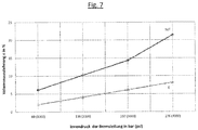
- the physical effect of the teaching of the invention is now in the diagram according to Fig. 7 explained in detail.
- As a filling for the brake lines a commercial DOT Class 4 brake fluid was used.
- a brake line according to the prior art has a volume expansion ⁇ of approximately 6%. Due to the inventive design of the brake lines 5a, 5b with strongly flattened cross-section of the braided thread strands 10, however, significantly lower volume changes are observed in the brake lines according to the invention, namely about 2% (marked with "E"). The extent of this different volume expansion ⁇ increases as the internal pressure of the brake pipe increases, as shown by the Fig. 7 is clearly visible. At an internal pressure of 138 bar shows the brake pipe according to the prior art, a volume expansion ⁇ of more than 10%, while this is about 4% in a brake pipe according to the invention 5a, 5b.
Landscapes
- Engineering & Computer Science (AREA)
- Transportation (AREA)
- Mechanical Engineering (AREA)
- Rigid Pipes And Flexible Pipes (AREA)
Applications Claiming Priority (1)
| Application Number | Priority Date | Filing Date | Title |
|---|---|---|---|
| DE202015104376.7U DE202015104376U1 (de) | 2015-08-19 | 2015-08-19 | Schlauchleitungssystem für eine hydraulische Zweirad-Bremsanlage |
Publications (2)
| Publication Number | Publication Date |
|---|---|
| EP3132986A1 true EP3132986A1 (fr) | 2017-02-22 |
| EP3132986B1 EP3132986B1 (fr) | 2017-11-01 |
Family
ID=56737916
Family Applications (1)
| Application Number | Title | Priority Date | Filing Date |
|---|---|---|---|
| EP16182919.7A Active EP3132986B1 (fr) | 2015-08-19 | 2016-08-05 | Systeme de conduite en tuyaux flexibles pour une installation de frein hydraulique de deux roues |
Country Status (2)
| Country | Link |
|---|---|
| EP (1) | EP3132986B1 (fr) |
| DE (1) | DE202015104376U1 (fr) |
Citations (5)
| Publication number | Priority date | Publication date | Assignee | Title |
|---|---|---|---|---|
| EP0148099A1 (fr) * | 1983-12-19 | 1985-07-10 | The Goodyear Tire & Rubber Company | Tuyau flexible avec armature noyeé et méthode pour sa fabrication |
| JPH1019172A (ja) * | 1996-07-04 | 1998-01-23 | Yokohama Rubber Co Ltd:The | 長尺高圧ホース及びその製造方法 |
| EP0982523A2 (fr) * | 1998-07-30 | 2000-03-01 | Toyoda Gosei Co., Ltd. | Tuyau de frein |
| EP1024320A1 (fr) * | 1999-01-29 | 2000-08-02 | Teleflex Fluid Systems, Inc. | Ensemble de tuyau flexible et procédé de sa fabrication |
| AU2012101666A4 (en) * | 2010-06-23 | 2012-12-06 | Fitt S.P.A | Flexible braided garden hose |
Family Cites Families (5)
| Publication number | Priority date | Publication date | Assignee | Title |
|---|---|---|---|---|
| US4111237A (en) * | 1976-07-12 | 1978-09-05 | General Motors Corporation | Braid reinforced flexible brake hose |
| US5381834A (en) * | 1993-09-14 | 1995-01-17 | Teleflex Incorporated | Hose assembly including reinforced layer having wear reducing fibers |
| US5445191A (en) * | 1994-08-11 | 1995-08-29 | General Motors Corporation | High pressure brake hose with reinforcing layer of nonwater-based adhesive coated polyvinyl alcohol fibers |
| US6341625B1 (en) * | 2000-01-10 | 2002-01-29 | Kanagawa Toyota Motor Sales Co., Ltd. | Hydraulic brake hose assembly for bicycles |
| US7748412B2 (en) * | 2008-08-05 | 2010-07-06 | Veyance Technologies Inc. | Hose having a single reinforcing layer |
-
2015
- 2015-08-19 DE DE202015104376.7U patent/DE202015104376U1/de not_active Expired - Lifetime
-
2016
- 2016-08-05 EP EP16182919.7A patent/EP3132986B1/fr active Active
Patent Citations (5)
| Publication number | Priority date | Publication date | Assignee | Title |
|---|---|---|---|---|
| EP0148099A1 (fr) * | 1983-12-19 | 1985-07-10 | The Goodyear Tire & Rubber Company | Tuyau flexible avec armature noyeé et méthode pour sa fabrication |
| JPH1019172A (ja) * | 1996-07-04 | 1998-01-23 | Yokohama Rubber Co Ltd:The | 長尺高圧ホース及びその製造方法 |
| EP0982523A2 (fr) * | 1998-07-30 | 2000-03-01 | Toyoda Gosei Co., Ltd. | Tuyau de frein |
| EP1024320A1 (fr) * | 1999-01-29 | 2000-08-02 | Teleflex Fluid Systems, Inc. | Ensemble de tuyau flexible et procédé de sa fabrication |
| AU2012101666A4 (en) * | 2010-06-23 | 2012-12-06 | Fitt S.P.A | Flexible braided garden hose |
Also Published As
| Publication number | Publication date |
|---|---|
| DE202015104376U1 (de) | 2016-12-08 |
| EP3132986B1 (fr) | 2017-11-01 |
Similar Documents
| Publication | Publication Date | Title |
|---|---|---|
| DE1600568C3 (de) | Drahtgeflechtverstarkter hy drauHscher Schlauch | |
| DE803800C (de) | Drahtkabel fuer metallische Einlagen von Luftreifen | |
| EP2935690B1 (fr) | Câble métallique et procédé et dispositif de fabrication du cable métallique | |
| DE2361181C2 (de) | Flexible Leitung oder Kabel mit einer zugfesten Bewehrung | |
| EP3190163B1 (fr) | Bande adhésive, en particulier bande à enrouler destinée à enrober des câbles dans des automobiles | |
| DE2505568B2 (de) | Seil zur bewehrung von gegenstaenden aus elastischen oder leicht verformbaren stoffen | |
| DE10108846B4 (de) | Bremsschlauch | |
| DE69503676T2 (de) | Verstärkung für Fahrzeugreifen | |
| DE60026214T2 (de) | Strickgarn aus expandiertem Graphit und Stopfbüchsenpackung | |
| EP1606448B1 (fr) | Procede pour realiser un cable | |
| DE102014115619A1 (de) | Spiralfeder und zugehöriges Herstellungsverfahren | |
| WO2016150804A1 (fr) | Tuyau en tôle ondulée multicouche | |
| DE2424665C3 (de) | Druckschlauch mit Verstärkungseinlagen | |
| EP3132986B1 (fr) | Systeme de conduite en tuyaux flexibles pour une installation de frein hydraulique de deux roues | |
| DE2653619A1 (de) | Bremsschlauch fuer hydraulische bremsanlagen | |
| EP3892451B1 (fr) | Procédé de fabrication permettant de fabriquer un composant renforcé par des fibres continues | |
| DE4107375A1 (de) | Zylinderrohr fuer einen arbeitszylinder | |
| DE102006007518A1 (de) | Abschirmgewebe | |
| DE2357557C2 (de) | Verstärkungseinlage für Leichtbaukörper | |
| CH706494A1 (de) | Kletterseil und Verfahren zur Herstellung. | |
| DE20217296U1 (de) | Drahtgewebe | |
| DE10334673B3 (de) | Herstellverfahren für einen Hochdruck-Dehnschlauch | |
| DE102018107331A1 (de) | Fahrradseil und Fahrradseilsystem mit diesem Fahrradseil | |
| EP2841795B1 (fr) | Unité de transfert de force | |
| DE2044995A1 (de) | Ringförmige Reifeneinlage fur Fahr zeugreifen |
Legal Events
| Date | Code | Title | Description |
|---|---|---|---|
| PUAI | Public reference made under article 153(3) epc to a published international application that has entered the european phase |
Free format text: ORIGINAL CODE: 0009012 |
|
| AK | Designated contracting states |
Kind code of ref document: A1 Designated state(s): AL AT BE BG CH CY CZ DE DK EE ES FI FR GB GR HR HU IE IS IT LI LT LU LV MC MK MT NL NO PL PT RO RS SE SI SK SM TR |
|
| AX | Request for extension of the european patent |
Extension state: BA ME |
|
| 17P | Request for examination filed |
Effective date: 20170413 |
|
| RBV | Designated contracting states (corrected) |
Designated state(s): AL AT BE BG CH CY CZ DE DK EE ES FI FR GB GR HR HU IE IS IT LI LT LU LV MC MK MT NL NO PL PT RO RS SE SI SK SM TR |
|
| GRAP | Despatch of communication of intention to grant a patent |
Free format text: ORIGINAL CODE: EPIDOSNIGR1 |
|
| INTG | Intention to grant announced |
Effective date: 20170530 |
|
| GRAS | Grant fee paid |
Free format text: ORIGINAL CODE: EPIDOSNIGR3 |
|
| GRAA | (expected) grant |
Free format text: ORIGINAL CODE: 0009210 |
|
| AK | Designated contracting states |
Kind code of ref document: B1 Designated state(s): AL AT BE BG CH CY CZ DE DK EE ES FI FR GB GR HR HU IE IS IT LI LT LU LV MC MK MT NL NO PL PT RO RS SE SI SK SM TR |
|
| REG | Reference to a national code |
Ref country code: GB Ref legal event code: FG4D Free format text: NOT ENGLISH |
|
| REG | Reference to a national code |
Ref country code: CH Ref legal event code: EP Ref country code: AT Ref legal event code: REF Ref document number: 941717 Country of ref document: AT Kind code of ref document: T Effective date: 20171115 |
|
| REG | Reference to a national code |
Ref country code: IE Ref legal event code: FG4D Free format text: LANGUAGE OF EP DOCUMENT: GERMAN |
|
| REG | Reference to a national code |
Ref country code: DE Ref legal event code: R096 Ref document number: 502016000243 Country of ref document: DE |
|
| REG | Reference to a national code |
Ref country code: NL Ref legal event code: MP Effective date: 20171101 |
|
| REG | Reference to a national code |
Ref country code: LT Ref legal event code: MG4D |
|
| PG25 | Lapsed in a contracting state [announced via postgrant information from national office to epo] |
Ref country code: NO Free format text: LAPSE BECAUSE OF FAILURE TO SUBMIT A TRANSLATION OF THE DESCRIPTION OR TO PAY THE FEE WITHIN THE PRESCRIBED TIME-LIMIT Effective date: 20180201 Ref country code: SE Free format text: LAPSE BECAUSE OF FAILURE TO SUBMIT A TRANSLATION OF THE DESCRIPTION OR TO PAY THE FEE WITHIN THE PRESCRIBED TIME-LIMIT Effective date: 20171101 Ref country code: LT Free format text: LAPSE BECAUSE OF FAILURE TO SUBMIT A TRANSLATION OF THE DESCRIPTION OR TO PAY THE FEE WITHIN THE PRESCRIBED TIME-LIMIT Effective date: 20171101 Ref country code: ES Free format text: LAPSE BECAUSE OF FAILURE TO SUBMIT A TRANSLATION OF THE DESCRIPTION OR TO PAY THE FEE WITHIN THE PRESCRIBED TIME-LIMIT Effective date: 20171101 Ref country code: FI Free format text: LAPSE BECAUSE OF FAILURE TO SUBMIT A TRANSLATION OF THE DESCRIPTION OR TO PAY THE FEE WITHIN THE PRESCRIBED TIME-LIMIT Effective date: 20171101 Ref country code: NL Free format text: LAPSE BECAUSE OF FAILURE TO SUBMIT A TRANSLATION OF THE DESCRIPTION OR TO PAY THE FEE WITHIN THE PRESCRIBED TIME-LIMIT Effective date: 20171101 |
|
| PG25 | Lapsed in a contracting state [announced via postgrant information from national office to epo] |
Ref country code: IS Free format text: LAPSE BECAUSE OF FAILURE TO SUBMIT A TRANSLATION OF THE DESCRIPTION OR TO PAY THE FEE WITHIN THE PRESCRIBED TIME-LIMIT Effective date: 20180301 Ref country code: RS Free format text: LAPSE BECAUSE OF FAILURE TO SUBMIT A TRANSLATION OF THE DESCRIPTION OR TO PAY THE FEE WITHIN THE PRESCRIBED TIME-LIMIT Effective date: 20171101 Ref country code: LV Free format text: LAPSE BECAUSE OF FAILURE TO SUBMIT A TRANSLATION OF THE DESCRIPTION OR TO PAY THE FEE WITHIN THE PRESCRIBED TIME-LIMIT Effective date: 20171101 Ref country code: BG Free format text: LAPSE BECAUSE OF FAILURE TO SUBMIT A TRANSLATION OF THE DESCRIPTION OR TO PAY THE FEE WITHIN THE PRESCRIBED TIME-LIMIT Effective date: 20180201 Ref country code: GR Free format text: LAPSE BECAUSE OF FAILURE TO SUBMIT A TRANSLATION OF THE DESCRIPTION OR TO PAY THE FEE WITHIN THE PRESCRIBED TIME-LIMIT Effective date: 20180202 Ref country code: HR Free format text: LAPSE BECAUSE OF FAILURE TO SUBMIT A TRANSLATION OF THE DESCRIPTION OR TO PAY THE FEE WITHIN THE PRESCRIBED TIME-LIMIT Effective date: 20171101 |
|
| PG25 | Lapsed in a contracting state [announced via postgrant information from national office to epo] |
Ref country code: CZ Free format text: LAPSE BECAUSE OF FAILURE TO SUBMIT A TRANSLATION OF THE DESCRIPTION OR TO PAY THE FEE WITHIN THE PRESCRIBED TIME-LIMIT Effective date: 20171101 Ref country code: CY Free format text: LAPSE BECAUSE OF FAILURE TO SUBMIT A TRANSLATION OF THE DESCRIPTION OR TO PAY THE FEE WITHIN THE PRESCRIBED TIME-LIMIT Effective date: 20171101 Ref country code: EE Free format text: LAPSE BECAUSE OF FAILURE TO SUBMIT A TRANSLATION OF THE DESCRIPTION OR TO PAY THE FEE WITHIN THE PRESCRIBED TIME-LIMIT Effective date: 20171101 Ref country code: DK Free format text: LAPSE BECAUSE OF FAILURE TO SUBMIT A TRANSLATION OF THE DESCRIPTION OR TO PAY THE FEE WITHIN THE PRESCRIBED TIME-LIMIT Effective date: 20171101 Ref country code: SK Free format text: LAPSE BECAUSE OF FAILURE TO SUBMIT A TRANSLATION OF THE DESCRIPTION OR TO PAY THE FEE WITHIN THE PRESCRIBED TIME-LIMIT Effective date: 20171101 |
|
| REG | Reference to a national code |
Ref country code: FR Ref legal event code: PLFP Year of fee payment: 3 |
|
| REG | Reference to a national code |
Ref country code: DE Ref legal event code: R097 Ref document number: 502016000243 Country of ref document: DE |
|
| PG25 | Lapsed in a contracting state [announced via postgrant information from national office to epo] |
Ref country code: IT Free format text: LAPSE BECAUSE OF FAILURE TO SUBMIT A TRANSLATION OF THE DESCRIPTION OR TO PAY THE FEE WITHIN THE PRESCRIBED TIME-LIMIT Effective date: 20171101 Ref country code: PL Free format text: LAPSE BECAUSE OF FAILURE TO SUBMIT A TRANSLATION OF THE DESCRIPTION OR TO PAY THE FEE WITHIN THE PRESCRIBED TIME-LIMIT Effective date: 20171101 Ref country code: SM Free format text: LAPSE BECAUSE OF FAILURE TO SUBMIT A TRANSLATION OF THE DESCRIPTION OR TO PAY THE FEE WITHIN THE PRESCRIBED TIME-LIMIT Effective date: 20171101 |
|
| PLBE | No opposition filed within time limit |
Free format text: ORIGINAL CODE: 0009261 |
|
| STAA | Information on the status of an ep patent application or granted ep patent |
Free format text: STATUS: NO OPPOSITION FILED WITHIN TIME LIMIT |
|
| PG25 | Lapsed in a contracting state [announced via postgrant information from national office to epo] |
Ref country code: MT Free format text: LAPSE BECAUSE OF FAILURE TO SUBMIT A TRANSLATION OF THE DESCRIPTION OR TO PAY THE FEE WITHIN THE PRESCRIBED TIME-LIMIT Effective date: 20171101 |
|
| 26N | No opposition filed |
Effective date: 20180802 |
|
| PG25 | Lapsed in a contracting state [announced via postgrant information from national office to epo] |
Ref country code: MC Free format text: LAPSE BECAUSE OF FAILURE TO SUBMIT A TRANSLATION OF THE DESCRIPTION OR TO PAY THE FEE WITHIN THE PRESCRIBED TIME-LIMIT Effective date: 20171101 |
|
| PG25 | Lapsed in a contracting state [announced via postgrant information from national office to epo] |
Ref country code: TR Free format text: LAPSE BECAUSE OF FAILURE TO SUBMIT A TRANSLATION OF THE DESCRIPTION OR TO PAY THE FEE WITHIN THE PRESCRIBED TIME-LIMIT Effective date: 20171101 |
|
| PG25 | Lapsed in a contracting state [announced via postgrant information from national office to epo] |
Ref country code: PT Free format text: LAPSE BECAUSE OF FAILURE TO SUBMIT A TRANSLATION OF THE DESCRIPTION OR TO PAY THE FEE WITHIN THE PRESCRIBED TIME-LIMIT Effective date: 20171101 |
|
| PG25 | Lapsed in a contracting state [announced via postgrant information from national office to epo] |
Ref country code: RO Free format text: LAPSE BECAUSE OF FAILURE TO SUBMIT A TRANSLATION OF THE DESCRIPTION OR TO PAY THE FEE WITHIN THE PRESCRIBED TIME-LIMIT Effective date: 20171101 Ref country code: MK Free format text: LAPSE BECAUSE OF NON-PAYMENT OF DUE FEES Effective date: 20171101 Ref country code: HU Free format text: LAPSE BECAUSE OF FAILURE TO SUBMIT A TRANSLATION OF THE DESCRIPTION OR TO PAY THE FEE WITHIN THE PRESCRIBED TIME-LIMIT; INVALID AB INITIO Effective date: 20160805 |
|
| PG25 | Lapsed in a contracting state [announced via postgrant information from national office to epo] |
Ref country code: AL Free format text: LAPSE BECAUSE OF FAILURE TO SUBMIT A TRANSLATION OF THE DESCRIPTION OR TO PAY THE FEE WITHIN THE PRESCRIBED TIME-LIMIT Effective date: 20171101 |
|
| PGFP | Annual fee paid to national office [announced via postgrant information from national office to epo] |
Ref country code: IE Payment date: 20200731 Year of fee payment: 5 Ref country code: LU Payment date: 20200731 Year of fee payment: 5 |
|
| PG25 | Lapsed in a contracting state [announced via postgrant information from national office to epo] |
Ref country code: SI Free format text: LAPSE BECAUSE OF NON-PAYMENT OF DUE FEES Effective date: 20180805 |
|
| REG | Reference to a national code |
Ref country code: DE Ref legal event code: R081 Ref document number: 502016000243 Country of ref document: DE Owner name: REHAU INDUSTRIES SE & CO. KG, DE Free format text: FORMER OWNER: REHAU AG + CO, 95111 REHAU, DE |
|
| PG25 | Lapsed in a contracting state [announced via postgrant information from national office to epo] |
Ref country code: LU Free format text: LAPSE BECAUSE OF NON-PAYMENT OF DUE FEES Effective date: 20210805 |
|
| REG | Reference to a national code |
Ref country code: GB Ref legal event code: 732E Free format text: REGISTERED BETWEEN 20220505 AND 20220512 |
|
| REG | Reference to a national code |
Ref country code: AT Ref legal event code: PC Ref document number: 941717 Country of ref document: AT Kind code of ref document: T Owner name: REHAU INDUSTRIES SE & CO. KG, DE Effective date: 20220419 |
|
| REG | Reference to a national code |
Ref country code: BE Ref legal event code: PD Owner name: REHAU INDUSTRIES SE & CO. KG; DE Free format text: DETAILS ASSIGNMENT: CHANGE OF OWNER(S), OTHER; FORMER OWNER NAME: REHAU AG + CO Effective date: 20220414 |
|
| PG25 | Lapsed in a contracting state [announced via postgrant information from national office to epo] |
Ref country code: IE Free format text: LAPSE BECAUSE OF NON-PAYMENT OF DUE FEES Effective date: 20210805 |
|
| PGFP | Annual fee paid to national office [announced via postgrant information from national office to epo] |
Ref country code: GB Payment date: 20220725 Year of fee payment: 7 Ref country code: AT Payment date: 20220729 Year of fee payment: 7 |
|
| PGFP | Annual fee paid to national office [announced via postgrant information from national office to epo] |
Ref country code: FR Payment date: 20220725 Year of fee payment: 7 Ref country code: BE Payment date: 20220729 Year of fee payment: 7 |
|
| PGFP | Annual fee paid to national office [announced via postgrant information from national office to epo] |
Ref country code: CH Payment date: 20220803 Year of fee payment: 7 |
|
| REG | Reference to a national code |
Ref country code: CH Ref legal event code: PL |
|
| REG | Reference to a national code |
Ref country code: AT Ref legal event code: MM01 Ref document number: 941717 Country of ref document: AT Kind code of ref document: T Effective date: 20230805 |
|
| PG25 | Lapsed in a contracting state [announced via postgrant information from national office to epo] |
Ref country code: AT Free format text: LAPSE BECAUSE OF NON-PAYMENT OF DUE FEES Effective date: 20230805 |
|
| GBPC | Gb: european patent ceased through non-payment of renewal fee |
Effective date: 20230805 |
|
| PG25 | Lapsed in a contracting state [announced via postgrant information from national office to epo] |
Ref country code: AT Free format text: LAPSE BECAUSE OF NON-PAYMENT OF DUE FEES Effective date: 20230805 Ref country code: CH Free format text: LAPSE BECAUSE OF NON-PAYMENT OF DUE FEES Effective date: 20230831 |
|
| REG | Reference to a national code |
Ref country code: BE Ref legal event code: MM Effective date: 20230831 |
|
| PG25 | Lapsed in a contracting state [announced via postgrant information from national office to epo] |
Ref country code: GB Free format text: LAPSE BECAUSE OF NON-PAYMENT OF DUE FEES Effective date: 20230805 |
|
| PG25 | Lapsed in a contracting state [announced via postgrant information from national office to epo] |
Ref country code: GB Free format text: LAPSE BECAUSE OF NON-PAYMENT OF DUE FEES Effective date: 20230805 Ref country code: FR Free format text: LAPSE BECAUSE OF NON-PAYMENT OF DUE FEES Effective date: 20230831 |
|
| PG25 | Lapsed in a contracting state [announced via postgrant information from national office to epo] |
Ref country code: BE Free format text: LAPSE BECAUSE OF NON-PAYMENT OF DUE FEES Effective date: 20230831 |
|
| PGFP | Annual fee paid to national office [announced via postgrant information from national office to epo] |
Ref country code: DE Payment date: 20250831 Year of fee payment: 10 |