EP3133228A2 - Eine modulare zaunanordnung - Google Patents
Eine modulare zaunanordnung Download PDFInfo
- Publication number
- EP3133228A2 EP3133228A2 EP16180830.8A EP16180830A EP3133228A2 EP 3133228 A2 EP3133228 A2 EP 3133228A2 EP 16180830 A EP16180830 A EP 16180830A EP 3133228 A2 EP3133228 A2 EP 3133228A2
- Authority
- EP
- European Patent Office
- Prior art keywords
- uprights
- structure according
- upright
- shaped notches
- connection
- Prior art date
- Legal status (The legal status is an assumption and is not a legal conclusion. Google has not performed a legal analysis and makes no representation as to the accuracy of the status listed.)
- Granted
Links
Images


Classifications
-
- E—FIXED CONSTRUCTIONS
- E04—BUILDING
- E04H—BUILDINGS OR LIKE STRUCTURES FOR PARTICULAR PURPOSES; SWIMMING OR SPLASH BATHS OR POOLS; MASTS; FENCING; TENTS OR CANOPIES, IN GENERAL
- E04H17/00—Fencing, e.g. fences, enclosures, corrals
- E04H17/14—Fences constructed of rigid elements, e.g. with additional wire fillings or with posts
- E04H17/20—Posts therefor
-
- E—FIXED CONSTRUCTIONS
- E04—BUILDING
- E04H—BUILDINGS OR LIKE STRUCTURES FOR PARTICULAR PURPOSES; SWIMMING OR SPLASH BATHS OR POOLS; MASTS; FENCING; TENTS OR CANOPIES, IN GENERAL
- E04H17/00—Fencing, e.g. fences, enclosures, corrals
- E04H17/14—Fences constructed of rigid elements, e.g. with additional wire fillings or with posts
- E04H17/1413—Post-and-rail fences, e.g. without vertical cross-members
- E04H17/1417—Post-and-rail fences, e.g. without vertical cross-members with vertical cross-members
- E04H17/1426—Picket fences
- E04H17/143—Picket fences with separate pickets attached to the side of the horizontal members
-
- E—FIXED CONSTRUCTIONS
- E04—BUILDING
- E04H—BUILDINGS OR LIKE STRUCTURES FOR PARTICULAR PURPOSES; SWIMMING OR SPLASH BATHS OR POOLS; MASTS; FENCING; TENTS OR CANOPIES, IN GENERAL
- E04H17/00—Fencing, e.g. fences, enclosures, corrals
- E04H17/14—Fences constructed of rigid elements, e.g. with additional wire fillings or with posts
- E04H17/1413—Post-and-rail fences, e.g. without vertical cross-members
- E04H17/1447—Details of connections between rails and posts
- E04H17/1452—Details of connections between rails and posts the ends of the rails are fixed on the lateral sides of the posts
-
- E—FIXED CONSTRUCTIONS
- E04—BUILDING
- E04H—BUILDINGS OR LIKE STRUCTURES FOR PARTICULAR PURPOSES; SWIMMING OR SPLASH BATHS OR POOLS; MASTS; FENCING; TENTS OR CANOPIES, IN GENERAL
- E04H17/00—Fencing, e.g. fences, enclosures, corrals
- E04H17/14—Fences constructed of rigid elements, e.g. with additional wire fillings or with posts
- E04H17/1413—Post-and-rail fences, e.g. without vertical cross-members
- E04H17/1447—Details of connections between rails and posts
- E04H17/146—Details of connections between rails and posts the rails being attached to the front faces of the posts
-
- E—FIXED CONSTRUCTIONS
- E04—BUILDING
- E04H—BUILDINGS OR LIKE STRUCTURES FOR PARTICULAR PURPOSES; SWIMMING OR SPLASH BATHS OR POOLS; MASTS; FENCING; TENTS OR CANOPIES, IN GENERAL
- E04H17/00—Fencing, e.g. fences, enclosures, corrals
- E04H17/14—Fences constructed of rigid elements, e.g. with additional wire fillings or with posts
- E04H17/1413—Post-and-rail fences, e.g. without vertical cross-members
- E04H17/1447—Details of connections between rails and posts
- E04H17/1465—Details of connections between rails and posts the rails being supported within blind or through holes of the posts
Definitions
- the present finding refers to a modular fence structure with high mounting simplicity and reduced maintenance.
- Such fencing is generally constituted by wooden prefabricated structural elements that are assembled together by using various connection systems.
- the fences of known type also have criticalities tied, for example, to the mounting, and in particular to the connection of the crosspieces with the uprights.
- the task of the present finding is therefore that of attaining a modular fence structure which overcomes the drawbacks of the abovementioned prior art, and which in particular is simple to make and assemble.
- one particular object of the finding is to provide a modular fence structure that is obtained with materials capable of combining high resistance to wear and signs of time with limited environmental and landscape impact.
- Another object of the finding is to provide a modular fence structure which allows considerably reducing the costs of labor during the achievement step.
- Still another object of the finding is to provide a modular fence structure which allows increasing the array of the achievable models, starting from the same structural components.
- Not least object of the finding is to provide a modular fence structure which is capable of ensuring the widest assurances of reliability and safety during use.
- a modular fence structure comprising a plurality of uprights adapted to support a plurality of transverse containment elements; said uprights being constituted by metal tubular bodies; said structure is characterized in that said uprights comprise a plurality of shaped notches, made along the extension thereof, adapted to allow the quick and safe connection of said containment elements.
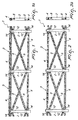
- a modular fence structure is indicated in its entirety with the reference number 1.
- the structure 1 is essentially composed of a series of uprights 2 suitable for a vertical fixing to the ground and conceived for supporting transverse containment elements 3.
- the uprights 2 are constituted by metal tubular bodies preferably made of COR-TEN steel, or of other materials with substantially analogous characteristics, which can have substantially circular or polygonal cross section, in accordance with the requirements.
- COR-TEN steel among the various available materials, is determined by the desire to intervene on the territory with minimum environmental and landscape impact, without however compromising the strength of the structure 1 as well as its ease of assembly.
- the containment elements 3 are constituted by stringers 4, preferably made of wood or round, semi-round or square steel, jointed to the uprights 2 and arranged on one or more superimposed horizontal rows.
- the stringers 4 are combined with oblique crosspieces 5, preferably made of half-round or square wood, associated with the uprights 2 and arranged as St. Andrew's Cross.
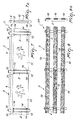
- the containment elements 3 can be constituted by metal rods 6, preferably made of COR-TEN steel, joined to the uprights 2 and equipped with vertically arranged boards 7.
- the containment elements 3 can instead consist of gridlike modular panels, as illustrated as an example in figures 5 and 6 in which they are respectively indicated with the reference numbers 8 and 9, or of cover panels 10, transparent or not transparent, as illustrated in figure 7 .
- containment elements 3 could also be constituted by nets, ropes, windbreak panels, and still other items, without departing from the scope of the employed solution idea.
- shaped notches 11 are defined which allow quickly and safely connecting the containment elements 3.
- shaped notches 11 illustrated in figures 1 to 7 have a shape substantially complementary to that of the cross section of suitable fixing elements 12, which are made integral with the containment elements 3 and associable with the uprights 2.
- diametrically-opposed pairs of shaped notches 11 define through seats for the fixing elements 12 on the uprights 2, which are inserted therein, with possibility of sliding in a manner such to traverse the same uprights 2 from side to side, projecting from opposite sides.
- the shaped notches 11 have size corresponding to the cross section of the fixing elements 12, such that one or each fixing elements 12 is insertable to size, hence substantially without clearance, in the respective shaped notch 11.
- the complementarity between a shaped notch 11 and a respective fixing element means that only a respective fixing element 12 is insertable in the shaped notch 11 or in each of the shaped notches 11 and therefore not a containment element to be supported, whose ends are thus not inserted in the axial opening of respective uprights.
- this ensures stronger uprights as well as a quick and effective insertion of the fixing element 12 in the shaped notch 11, as well as the maintenance in correct work position of the fixing element 12, in particular as long as the same is not connected or fixed to one or more containment elements.
- pairs of shaped notches 11 are defined on the side of the uprights 2, at the top part and bottom part, i.e. substantially at the two opposite ends of the portions of the uprights 2 that project from the ground.
- the shaped notches 11 are advantageously elongated slots defined longitudinally or transversely with respect to the uprights 2.
- the aforesaid elongated slots can be defined in a manner such to be operatively vertical or operatively horizontal in accordance with the requirements.
- the fixing elements 12 instead consist of a series of metal plates, preferably made of COR-TEN steel, which suitably have slotted holes 13 made on the opposite ends thereof.
- the slotted holes 13 allow fixing the containment elements 3 to the aforesaid plates by means of screws 14, bolts, rivets, or other equivalent connection members.
- such plates can also comprise mechanical blocks, constituted for example by projections that project from their profile, which fix the length of the plate sections insertable in the shaped notches 11 and block the sliding thereof relative to the uprights 2.
- the uprights 2 can also comprise holes 15, or grooves 16, conceived in a manner such to receive the ends of the stringers 4.
- the shaped notches can assume a different shape.
- some or all the shaped notches 111 can be substantially H-shaped, in a manner so as to define wings 17 on the front of the uprights 2, such wings 17 being susceptible of being bent towards each other, in a manner such to substantially form flat connection zones where it is possible to easily set and fix the containment elements 3.
- bending raisers 18 can be provided that are essentially constituted by perforated slits.
- the containment elements 3 can be constituted by bars 19, preferably made of round, semi-round or square wood, joined to the wings 17 by means of self-drilling screws.
- the use of the laser in cutting the uprights 2 allows executing complex cutting lines with high precision, reducing both the times for making the fence according to the finding, and the working discards.
- the assembly of the modular fence structure is particularly simple and quick.
- the structure is initially disassembled and its assembly starts with the installation of the uprights 2 which represent the essential elements for supporting the entire structure.
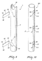
- the uprights 2 can be laid in various ways, for example by means of obtaining suitable concrete foundations, clamped with screws or screw anchors or by means of the pin system as represented in figures 11, 12, 13 .
- a modular fence structure 1a which comprises at least one upright 2 adapted to support at least one transverse containment element (as indicated above with reference to figures 1 to 10 ) and/or at least one stringer 4, for example as described above; such upright 2 is constituted by a tubular body, if desired metallic.
- connection and support element 20 e.g. a bar or round bar or pin, if desired made of iron, for the connection, e.g. removable, to the ground or to a curb or low wall constrained or fixed to the ground S of the upright 2 and the support thereof;
- connection and support element 20 is, on one side, connectable or fixable or fitted in the ground S or in a curb or low wall and on the other side it is insertable or inserted in the through hole 2a delimited by a respective upright 2 or in any case it can be arranged side-by-side or outside a respective upright 2.
- connection and support element 20 is arranged adjacent to and, if desired, in contact for the entire longitudinal extension thereof with the upright 2, in particular a lower, in use, internal surface section 2c of the upright 2.
- connection and support element 20 is preferably parallel to the longitudinal extension axis of the respective upright 2.
- the structure also comprises means 21, 22 for constraining or engaging the connection and support element 20 with the upright or with the respective upright 2.
- the means for constraining 21, 22 can comprise at least one U-shaped or C-shaped clamp or bracket 21 enclosing or at least partially placed around the connection and support element 20 and with at least one free end 21 a inserted in and constrained to the upright 2 or to the lateral wall thereof.
- one or both free ends 21a of the clamp 21 is/are threaded and in such case the structure comprises at least one nut or a pair of nuts 22, each in screwing engagement with a threaded free end 21 a; each nut 22 preferably abuts against the external surface 2b of the upright 2, in particular if the connection and support element 20 is inserted in the upright 2 or against the internal surface 2c of the upright, in particular if the connection and support element 20 flanks, from the outside, the upright 2, but in both cases such to constrain the upright 2 to the clamp 21 and to the connection and support element 20.
- the clamp or bracket encloses the connection and support element 20 and due to the nut 22 tightens - preferably removably - the connection and support element 20 against the external surface 2b or internal surface 2c of the upright 2.
- connection and support elements 20 With one such structure it is possible to removably fix the uprights 2 in the ground. To do this, one first installs the connection and support elements 20 in the ground, if desired by means of the use of pile-driver devices, for example in a layer of fresh concrete previously deposited on the ground, or one covers the connection and support elements 20 with resin and then the same are inserted or fixed in cement curbs or low walls.
- tubular uprights are fixed, previously provided with holes by means of suitable clamps.
- a structure or system like that illustrated in figures 11 to 13 allows a removable mounting of one or more uprights and can for example be used for cleaning embankments and slopes.
- the pin or round bar 20 can also be made of a traditional steel lined for reinforced concrete, which can have anti-rotation characteristics and be knurled, in which case it ensures an increased adherence both to the ground and with regard to the surface of the respective upright 2.
- the uprights 2 and the stringers 3 are obtained by means of laser technology and do not require subsequent working, in particular manual workshop working, e.g. welding, perforating, smoothing etcetera.
- the pin or round bar 20 can have length equal to about 20-120 cm, for example about 80-120 cm, if desired 100 cm for fixing on the ground, or for example 20-60 cm, if desired 40 cm for fixing on concrete.
- the pin 20 can be fitted or inserted for about 70-90% of its length, e.g. 80%, in the ground or about 40-60% of its length, e.g. 50%, in concrete.
- Part of the structure according to the finding is in fact made of COR-TEN steel and therefore is capable both of self-protection from electrochemical corrosion, with undoubted advantages in terms of fence duration and safety, and of maintaining low environmental and landscape impact.
- Another advantage of the modular fence structure according to the finding lies in the reduced bulk of the disassembled components; such property facilitates both the storage and the transport.
Landscapes
- Engineering & Computer Science (AREA)
- Architecture (AREA)
- Civil Engineering (AREA)
- Structural Engineering (AREA)
- Fencing (AREA)
- Mechanical Coupling Of Light Guides (AREA)
- Control Of Motors That Do Not Use Commutators (AREA)
- Magnetically Actuated Valves (AREA)
Priority Applications (2)
| Application Number | Priority Date | Filing Date | Title |
|---|---|---|---|
| EP20160009.5A EP3683385B1 (de) | 2016-07-22 | 2017-07-14 | Modulare zaunanordnung |
| EP17181527.7A EP3272971B1 (de) | 2016-07-22 | 2017-07-14 | Zaunkonstruktion |
Applications Claiming Priority (1)
| Application Number | Priority Date | Filing Date | Title |
|---|---|---|---|
| ITUB2015A002380A ITUB20152380A1 (it) | 2015-07-22 | 2015-07-22 | Struttura di staccionata componibile |
Publications (3)
| Publication Number | Publication Date |
|---|---|
| EP3133228A2 true EP3133228A2 (de) | 2017-02-22 |
| EP3133228A3 EP3133228A3 (de) | 2017-03-22 |
| EP3133228B1 EP3133228B1 (de) | 2021-02-17 |
Family
ID=54289022
Family Applications (1)
| Application Number | Title | Priority Date | Filing Date |
|---|---|---|---|
| EP16180830.8A Active EP3133228B1 (de) | 2015-07-22 | 2016-07-22 | Eine modulare zaunanordnung |
Country Status (2)
| Country | Link |
|---|---|
| EP (1) | EP3133228B1 (de) |
| IT (1) | ITUB20152380A1 (de) |
Cited By (3)
| Publication number | Priority date | Publication date | Assignee | Title |
|---|---|---|---|---|
| US9963854B2 (en) * | 2015-11-10 | 2018-05-08 | Caterpillar Inc. | Guardrail with tapered vertical channel post |
| CN111827778A (zh) * | 2020-06-23 | 2020-10-27 | 北京住总第一开发建设有限公司 | 一种方便组装的装配式护栏 |
| GB2595287A (en) * | 2020-05-21 | 2021-11-24 | Perforated & Stamped Products Ltd | A partition assembly |
Citations (4)
| Publication number | Priority date | Publication date | Assignee | Title |
|---|---|---|---|---|
| US666947A (en) | 1899-12-21 | 1901-01-29 | Joseph T Ward | Fence-joint. |
| US4813651A (en) | 1988-06-30 | 1989-03-21 | Rutledge Terry G | Fence post with saddle support construction and method therefore |
| DE4436345C1 (de) | 1994-10-12 | 1996-02-08 | V & S Sicherungssysteme Gmbh & | Gitterzaun mit einrastenden Haltebügeln |
| US20030222257A1 (en) | 2001-06-05 | 2003-12-04 | Bebendorf Ronald William | Fence post and rail assembly with concealed strengthening bars |
-
2015
- 2015-07-22 IT ITUB2015A002380A patent/ITUB20152380A1/it unknown
-
2016
- 2016-07-22 EP EP16180830.8A patent/EP3133228B1/de active Active
Patent Citations (4)
| Publication number | Priority date | Publication date | Assignee | Title |
|---|---|---|---|---|
| US666947A (en) | 1899-12-21 | 1901-01-29 | Joseph T Ward | Fence-joint. |
| US4813651A (en) | 1988-06-30 | 1989-03-21 | Rutledge Terry G | Fence post with saddle support construction and method therefore |
| DE4436345C1 (de) | 1994-10-12 | 1996-02-08 | V & S Sicherungssysteme Gmbh & | Gitterzaun mit einrastenden Haltebügeln |
| US20030222257A1 (en) | 2001-06-05 | 2003-12-04 | Bebendorf Ronald William | Fence post and rail assembly with concealed strengthening bars |
Cited By (4)
| Publication number | Priority date | Publication date | Assignee | Title |
|---|---|---|---|---|
| US9963854B2 (en) * | 2015-11-10 | 2018-05-08 | Caterpillar Inc. | Guardrail with tapered vertical channel post |
| GB2595287A (en) * | 2020-05-21 | 2021-11-24 | Perforated & Stamped Products Ltd | A partition assembly |
| GB2595287B (en) * | 2020-05-21 | 2024-06-05 | Perforated & Stamped Products Ltd | A partition assembly |
| CN111827778A (zh) * | 2020-06-23 | 2020-10-27 | 北京住总第一开发建设有限公司 | 一种方便组装的装配式护栏 |
Also Published As
| Publication number | Publication date |
|---|---|
| EP3133228B1 (de) | 2021-02-17 |
| EP3133228A3 (de) | 2017-03-22 |
| ITUB20152380A1 (it) | 2017-01-22 |
Similar Documents
| Publication | Publication Date | Title |
|---|---|---|
| EP3045605B1 (de) | Modul zur herstellung von betonteilen | |
| US7913463B2 (en) | Adjustable vertical brace | |
| EP3133228B1 (de) | Eine modulare zaunanordnung | |
| EP3683385B1 (de) | Modulare zaunanordnung | |
| EP3514301A1 (de) | Schalungszwinge | |
| DE2720277A1 (de) | Befestigungseinrichtung an gewaechshaeusern mit abflussrinnen | |
| DE202007006279U1 (de) | Zaunmodul für ein demontierbares modulares Zaunfeld und Zaunfeld | |
| DE102020116734B4 (de) | Hordengatter | |
| DE202015106999U1 (de) | Verbesserte Schalungsstruktur zur Ausführung von Horizontalgüssen zur Bereitstellung von Decken | |
| DE1683167B2 (de) | Wandverkleidung fuer aussenwaende | |
| DE102008010696A1 (de) | Holzfußboden für den Außenbereich | |
| KR20070025483A (ko) | 교량 건설용 일체식 동바리 | |
| DE19542155C1 (de) | Tragkonstruktion für Bodenplatten | |
| DE1224021B (de) | Rinnenfoermige Schalung zum Betonieren von Traegern, Unterzuegen od. dgl. | |
| RU73011U1 (ru) | Панель решетчатого ограждения | |
| RU138193U1 (ru) | Модуль каркаса арочной теплицы (варианты) | |
| KR200408920Y1 (ko) | 교량 건설용 일체식 동바리 | |
| DE227576C (de) | ||
| EP3712347A1 (de) | Befestigungspfosten für ein vorlaufendes geländer, vorlaufendes geländer zur vorübergehenden fallsicherung einer neu zu erstellenden gerüstebene, gerüst für bau-, reparatur- und/oder montagearbeiten und verfahren zum aufbauen eines gerüsts | |
| RU148524U1 (ru) | Столбик для забора (варианты) | |
| RU154220U1 (ru) | Устройство для стыкового соединения профилей и профильных труб разного сечения | |
| KR970005544Y1 (ko) | 지하 옹벽 구축용 거푸집 고정장치 | |
| JP2007032124A (ja) | ブロック塀補強構造 | |
| AT14522U1 (de) | Vorrichtung zum Trocknen von Mähgut | |
| DE9315802U1 (de) | Abschalwinkel |
Legal Events
| Date | Code | Title | Description |
|---|---|---|---|
| PUAI | Public reference made under article 153(3) epc to a published international application that has entered the european phase |
Free format text: ORIGINAL CODE: 0009012 |
|
| STAA | Information on the status of an ep patent application or granted ep patent |
Free format text: STATUS: THE APPLICATION HAS BEEN PUBLISHED |
|
| PUAL | Search report despatched |
Free format text: ORIGINAL CODE: 0009013 |
|
| AK | Designated contracting states |
Kind code of ref document: A2 Designated state(s): AL AT BE BG CH CY CZ DE DK EE ES FI FR GB GR HR HU IE IS IT LI LT LU LV MC MK MT NL NO PL PT RO RS SE SI SK SM TR |
|
| AX | Request for extension of the european patent |
Extension state: BA ME |
|
| AK | Designated contracting states |
Kind code of ref document: A3 Designated state(s): AL AT BE BG CH CY CZ DE DK EE ES FI FR GB GR HR HU IE IS IT LI LT LU LV MC MK MT NL NO PL PT RO RS SE SI SK SM TR |
|
| AX | Request for extension of the european patent |
Extension state: BA ME |
|
| RIC1 | Information provided on ipc code assigned before grant |
Ipc: E04H 17/14 20060101AFI20170215BHEP Ipc: E04H 17/20 20060101ALI20170215BHEP |
|
| STAA | Information on the status of an ep patent application or granted ep patent |
Free format text: STATUS: REQUEST FOR EXAMINATION WAS MADE |
|
| 17P | Request for examination filed |
Effective date: 20170912 |
|
| RBV | Designated contracting states (corrected) |
Designated state(s): AL AT BE BG CH CY CZ DE DK EE ES FI FR GB GR HR HU IE IS IT LI LT LU LV MC MK MT NL NO PL PT RO RS SE SI SK SM TR |
|
| STAA | Information on the status of an ep patent application or granted ep patent |
Free format text: STATUS: EXAMINATION IS IN PROGRESS |
|
| 17Q | First examination report despatched |
Effective date: 20180703 |
|
| RAP1 | Party data changed (applicant data changed or rights of an application transferred) |
Owner name: CRACCO S.R.L. |
|
| GRAP | Despatch of communication of intention to grant a patent |
Free format text: ORIGINAL CODE: EPIDOSNIGR1 |
|
| STAA | Information on the status of an ep patent application or granted ep patent |
Free format text: STATUS: GRANT OF PATENT IS INTENDED |
|
| INTG | Intention to grant announced |
Effective date: 20200911 |
|
| GRAS | Grant fee paid |
Free format text: ORIGINAL CODE: EPIDOSNIGR3 |
|
| GRAA | (expected) grant |
Free format text: ORIGINAL CODE: 0009210 |
|
| STAA | Information on the status of an ep patent application or granted ep patent |
Free format text: STATUS: THE PATENT HAS BEEN GRANTED |
|
| AK | Designated contracting states |
Kind code of ref document: B1 Designated state(s): AL AT BE BG CH CY CZ DE DK EE ES FI FR GB GR HR HU IE IS IT LI LT LU LV MC MK MT NL NO PL PT RO RS SE SI SK SM TR |
|
| REG | Reference to a national code |
Ref country code: GB Ref legal event code: FG4D |
|
| REG | Reference to a national code |
Ref country code: CH Ref legal event code: EP |
|
| REG | Reference to a national code |
Ref country code: DE Ref legal event code: R096 Ref document number: 602016052478 Country of ref document: DE |
|
| REG | Reference to a national code |
Ref country code: AT Ref legal event code: REF Ref document number: 1361670 Country of ref document: AT Kind code of ref document: T Effective date: 20210315 |
|
| REG | Reference to a national code |
Ref country code: IE Ref legal event code: FG4D |
|
| REG | Reference to a national code |
Ref country code: CH Ref legal event code: NV Representative=s name: VALIPAT S.A. C/O BOVARD SA NEUCHATEL, CH |
|
| REG | Reference to a national code |
Ref country code: NL Ref legal event code: FP |
|
| REG | Reference to a national code |
Ref country code: LT Ref legal event code: MG9D |
|
| PG25 | Lapsed in a contracting state [announced via postgrant information from national office to epo] |
Ref country code: BG Free format text: LAPSE BECAUSE OF FAILURE TO SUBMIT A TRANSLATION OF THE DESCRIPTION OR TO PAY THE FEE WITHIN THE PRESCRIBED TIME-LIMIT Effective date: 20210517 Ref country code: FI Free format text: LAPSE BECAUSE OF FAILURE TO SUBMIT A TRANSLATION OF THE DESCRIPTION OR TO PAY THE FEE WITHIN THE PRESCRIBED TIME-LIMIT Effective date: 20210217 Ref country code: GR Free format text: LAPSE BECAUSE OF FAILURE TO SUBMIT A TRANSLATION OF THE DESCRIPTION OR TO PAY THE FEE WITHIN THE PRESCRIBED TIME-LIMIT Effective date: 20210518 Ref country code: HR Free format text: LAPSE BECAUSE OF FAILURE TO SUBMIT A TRANSLATION OF THE DESCRIPTION OR TO PAY THE FEE WITHIN THE PRESCRIBED TIME-LIMIT Effective date: 20210217 Ref country code: LT Free format text: LAPSE BECAUSE OF FAILURE TO SUBMIT A TRANSLATION OF THE DESCRIPTION OR TO PAY THE FEE WITHIN THE PRESCRIBED TIME-LIMIT Effective date: 20210217 Ref country code: PT Free format text: LAPSE BECAUSE OF FAILURE TO SUBMIT A TRANSLATION OF THE DESCRIPTION OR TO PAY THE FEE WITHIN THE PRESCRIBED TIME-LIMIT Effective date: 20210617 Ref country code: NO Free format text: LAPSE BECAUSE OF FAILURE TO SUBMIT A TRANSLATION OF THE DESCRIPTION OR TO PAY THE FEE WITHIN THE PRESCRIBED TIME-LIMIT Effective date: 20210517 |
|
| REG | Reference to a national code |
Ref country code: AT Ref legal event code: MK05 Ref document number: 1361670 Country of ref document: AT Kind code of ref document: T Effective date: 20210217 |
|
| PG25 | Lapsed in a contracting state [announced via postgrant information from national office to epo] |
Ref country code: SE Free format text: LAPSE BECAUSE OF FAILURE TO SUBMIT A TRANSLATION OF THE DESCRIPTION OR TO PAY THE FEE WITHIN THE PRESCRIBED TIME-LIMIT Effective date: 20210217 Ref country code: RS Free format text: LAPSE BECAUSE OF FAILURE TO SUBMIT A TRANSLATION OF THE DESCRIPTION OR TO PAY THE FEE WITHIN THE PRESCRIBED TIME-LIMIT Effective date: 20210217 Ref country code: LV Free format text: LAPSE BECAUSE OF FAILURE TO SUBMIT A TRANSLATION OF THE DESCRIPTION OR TO PAY THE FEE WITHIN THE PRESCRIBED TIME-LIMIT Effective date: 20210217 Ref country code: PL Free format text: LAPSE BECAUSE OF FAILURE TO SUBMIT A TRANSLATION OF THE DESCRIPTION OR TO PAY THE FEE WITHIN THE PRESCRIBED TIME-LIMIT Effective date: 20210217 |
|
| PG25 | Lapsed in a contracting state [announced via postgrant information from national office to epo] |
Ref country code: IS Free format text: LAPSE BECAUSE OF FAILURE TO SUBMIT A TRANSLATION OF THE DESCRIPTION OR TO PAY THE FEE WITHIN THE PRESCRIBED TIME-LIMIT Effective date: 20210617 |
|
| PG25 | Lapsed in a contracting state [announced via postgrant information from national office to epo] |
Ref country code: EE Free format text: LAPSE BECAUSE OF FAILURE TO SUBMIT A TRANSLATION OF THE DESCRIPTION OR TO PAY THE FEE WITHIN THE PRESCRIBED TIME-LIMIT Effective date: 20210217 Ref country code: CZ Free format text: LAPSE BECAUSE OF FAILURE TO SUBMIT A TRANSLATION OF THE DESCRIPTION OR TO PAY THE FEE WITHIN THE PRESCRIBED TIME-LIMIT Effective date: 20210217 Ref country code: AT Free format text: LAPSE BECAUSE OF FAILURE TO SUBMIT A TRANSLATION OF THE DESCRIPTION OR TO PAY THE FEE WITHIN THE PRESCRIBED TIME-LIMIT Effective date: 20210217 Ref country code: SM Free format text: LAPSE BECAUSE OF FAILURE TO SUBMIT A TRANSLATION OF THE DESCRIPTION OR TO PAY THE FEE WITHIN THE PRESCRIBED TIME-LIMIT Effective date: 20210217 |
|
| REG | Reference to a national code |
Ref country code: DE Ref legal event code: R097 Ref document number: 602016052478 Country of ref document: DE |
|
| PG25 | Lapsed in a contracting state [announced via postgrant information from national office to epo] |
Ref country code: SK Free format text: LAPSE BECAUSE OF FAILURE TO SUBMIT A TRANSLATION OF THE DESCRIPTION OR TO PAY THE FEE WITHIN THE PRESCRIBED TIME-LIMIT Effective date: 20210217 Ref country code: DK Free format text: LAPSE BECAUSE OF FAILURE TO SUBMIT A TRANSLATION OF THE DESCRIPTION OR TO PAY THE FEE WITHIN THE PRESCRIBED TIME-LIMIT Effective date: 20210217 Ref country code: ES Free format text: LAPSE BECAUSE OF FAILURE TO SUBMIT A TRANSLATION OF THE DESCRIPTION OR TO PAY THE FEE WITHIN THE PRESCRIBED TIME-LIMIT Effective date: 20210217 Ref country code: RO Free format text: LAPSE BECAUSE OF FAILURE TO SUBMIT A TRANSLATION OF THE DESCRIPTION OR TO PAY THE FEE WITHIN THE PRESCRIBED TIME-LIMIT Effective date: 20210217 |
|
| PLBE | No opposition filed within time limit |
Free format text: ORIGINAL CODE: 0009261 |
|
| STAA | Information on the status of an ep patent application or granted ep patent |
Free format text: STATUS: NO OPPOSITION FILED WITHIN TIME LIMIT |
|
| 26N | No opposition filed |
Effective date: 20211118 |
|
| PG25 | Lapsed in a contracting state [announced via postgrant information from national office to epo] |
Ref country code: AL Free format text: LAPSE BECAUSE OF FAILURE TO SUBMIT A TRANSLATION OF THE DESCRIPTION OR TO PAY THE FEE WITHIN THE PRESCRIBED TIME-LIMIT Effective date: 20210217 |
|
| PG25 | Lapsed in a contracting state [announced via postgrant information from national office to epo] |
Ref country code: SI Free format text: LAPSE BECAUSE OF FAILURE TO SUBMIT A TRANSLATION OF THE DESCRIPTION OR TO PAY THE FEE WITHIN THE PRESCRIBED TIME-LIMIT Effective date: 20210217 |
|
| PG25 | Lapsed in a contracting state [announced via postgrant information from national office to epo] |
Ref country code: MC Free format text: LAPSE BECAUSE OF FAILURE TO SUBMIT A TRANSLATION OF THE DESCRIPTION OR TO PAY THE FEE WITHIN THE PRESCRIBED TIME-LIMIT Effective date: 20210217 |
|
| PG25 | Lapsed in a contracting state [announced via postgrant information from national office to epo] |
Ref country code: IS Free format text: LAPSE BECAUSE OF FAILURE TO SUBMIT A TRANSLATION OF THE DESCRIPTION OR TO PAY THE FEE WITHIN THE PRESCRIBED TIME-LIMIT Effective date: 20210617 Ref country code: LU Free format text: LAPSE BECAUSE OF NON-PAYMENT OF DUE FEES Effective date: 20210722 |
|
| PG25 | Lapsed in a contracting state [announced via postgrant information from national office to epo] |
Ref country code: IE Free format text: LAPSE BECAUSE OF NON-PAYMENT OF DUE FEES Effective date: 20210722 |
|
| PG25 | Lapsed in a contracting state [announced via postgrant information from national office to epo] |
Ref country code: HU Free format text: LAPSE BECAUSE OF FAILURE TO SUBMIT A TRANSLATION OF THE DESCRIPTION OR TO PAY THE FEE WITHIN THE PRESCRIBED TIME-LIMIT; INVALID AB INITIO Effective date: 20160722 |
|
| P01 | Opt-out of the competence of the unified patent court (upc) registered |
Effective date: 20230508 |
|
| PG25 | Lapsed in a contracting state [announced via postgrant information from national office to epo] |
Ref country code: CY Free format text: LAPSE BECAUSE OF FAILURE TO SUBMIT A TRANSLATION OF THE DESCRIPTION OR TO PAY THE FEE WITHIN THE PRESCRIBED TIME-LIMIT Effective date: 20210217 |
|
| PG25 | Lapsed in a contracting state [announced via postgrant information from national office to epo] |
Ref country code: MK Free format text: LAPSE BECAUSE OF FAILURE TO SUBMIT A TRANSLATION OF THE DESCRIPTION OR TO PAY THE FEE WITHIN THE PRESCRIBED TIME-LIMIT Effective date: 20210217 |
|
| PG25 | Lapsed in a contracting state [announced via postgrant information from national office to epo] |
Ref country code: MT Free format text: LAPSE BECAUSE OF FAILURE TO SUBMIT A TRANSLATION OF THE DESCRIPTION OR TO PAY THE FEE WITHIN THE PRESCRIBED TIME-LIMIT Effective date: 20210217 |
|
| PGFP | Annual fee paid to national office [announced via postgrant information from national office to epo] |
Ref country code: NL Payment date: 20250726 Year of fee payment: 10 |
|
| PGFP | Annual fee paid to national office [announced via postgrant information from national office to epo] |
Ref country code: DE Payment date: 20250729 Year of fee payment: 10 |
|
| PGFP | Annual fee paid to national office [announced via postgrant information from national office to epo] |
Ref country code: IT Payment date: 20250724 Year of fee payment: 10 |
|
| PGFP | Annual fee paid to national office [announced via postgrant information from national office to epo] |
Ref country code: BE Payment date: 20250728 Year of fee payment: 10 Ref country code: GB Payment date: 20250728 Year of fee payment: 10 |
|
| PGFP | Annual fee paid to national office [announced via postgrant information from national office to epo] |
Ref country code: FR Payment date: 20250725 Year of fee payment: 10 |
|
| PGFP | Annual fee paid to national office [announced via postgrant information from national office to epo] |
Ref country code: CH Payment date: 20250801 Year of fee payment: 10 |
|
| PG25 | Lapsed in a contracting state [announced via postgrant information from national office to epo] |
Ref country code: TR Free format text: LAPSE BECAUSE OF FAILURE TO SUBMIT A TRANSLATION OF THE DESCRIPTION OR TO PAY THE FEE WITHIN THE PRESCRIBED TIME-LIMIT Effective date: 20210217 |