EP3133384A2 - Dispositif et procede de recherche thermo-optique d'echantillons - Google Patents
Dispositif et procede de recherche thermo-optique d'echantillons Download PDFInfo
- Publication number
- EP3133384A2 EP3133384A2 EP16181543.6A EP16181543A EP3133384A2 EP 3133384 A2 EP3133384 A2 EP 3133384A2 EP 16181543 A EP16181543 A EP 16181543A EP 3133384 A2 EP3133384 A2 EP 3133384A2
- Authority
- EP
- European Patent Office
- Prior art keywords
- sample
- viewing
- light source
- vacuum
- climatic chamber
- Prior art date
- Legal status (The legal status is an assumption and is not a legal conclusion. Google has not performed a legal analysis and makes no representation as to the accuracy of the status listed.)
- Granted
Links
Images
Classifications
-
- G—PHYSICS
- G01—MEASURING; TESTING
- G01N—INVESTIGATING OR ANALYSING MATERIALS BY DETERMINING THEIR CHEMICAL OR PHYSICAL PROPERTIES
- G01N21/00—Investigating or analysing materials by the use of optical means, i.e. using sub-millimetre waves, infrared, visible or ultraviolet light
- G01N21/01—Arrangements or apparatus for facilitating the optical investigation
-
- G—PHYSICS
- G01—MEASURING; TESTING
- G01N—INVESTIGATING OR ANALYSING MATERIALS BY DETERMINING THEIR CHEMICAL OR PHYSICAL PROPERTIES
- G01N21/00—Investigating or analysing materials by the use of optical means, i.e. using sub-millimetre waves, infrared, visible or ultraviolet light
- G01N21/01—Arrangements or apparatus for facilitating the optical investigation
- G01N21/03—Cuvette constructions
- G01N21/0332—Cuvette constructions with temperature control
-
- G—PHYSICS
- G01—MEASURING; TESTING
- G01N—INVESTIGATING OR ANALYSING MATERIALS BY DETERMINING THEIR CHEMICAL OR PHYSICAL PROPERTIES
- G01N21/00—Investigating or analysing materials by the use of optical means, i.e. using sub-millimetre waves, infrared, visible or ultraviolet light
- G01N21/01—Arrangements or apparatus for facilitating the optical investigation
- G01N21/15—Preventing contamination of the components of the optical system or obstruction of the light path
-
- G—PHYSICS
- G01—MEASURING; TESTING
- G01N—INVESTIGATING OR ANALYSING MATERIALS BY DETERMINING THEIR CHEMICAL OR PHYSICAL PROPERTIES
- G01N21/00—Investigating or analysing materials by the use of optical means, i.e. using sub-millimetre waves, infrared, visible or ultraviolet light
- G01N21/01—Arrangements or apparatus for facilitating the optical investigation
- G01N21/15—Preventing contamination of the components of the optical system or obstruction of the light path
- G01N2021/155—Monitoring cleanness of window, lens, or other parts
-
- G—PHYSICS
- G01—MEASURING; TESTING
- G01N—INVESTIGATING OR ANALYSING MATERIALS BY DETERMINING THEIR CHEMICAL OR PHYSICAL PROPERTIES
- G01N21/00—Investigating or analysing materials by the use of optical means, i.e. using sub-millimetre waves, infrared, visible or ultraviolet light
- G01N21/01—Arrangements or apparatus for facilitating the optical investigation
- G01N21/15—Preventing contamination of the components of the optical system or obstruction of the light path
- G01N2021/158—Eliminating condensation
Definitions
- the present invention relates to a device for the thermo-optical examination of samples.
- the device has two viewing openings, which are each sealed vacuum-tight with a sortvakuumflansch.
- a sample plate is arranged within the climatic cabinet between the reformvakuumflanschen.
- at least one light source and at least one light detector outside the climatic chamber are arranged so that at least one extending from a light source to a light detector optical axis of view passes through the two viewing windows of the two withdrawvakuumflansche and arranged on the sample plate sample.
- the present invention also relates to a method for the thermo-optical examination of samples with a device according to the invention.
- the invention thus provides a device for the thermo-optical examination of samples.
- the apparatus includes a climatic cabinet with two arranged on opposite sides of the climatic cabinet viewing ports, both viewing ports each having a prepare for the thermo-optical examination of samples, are sealed vacuum-tight.
- the device contains a sample tray arranged inside the climatic cabinet between the visual vacuum flanges, at least one light source and at least one light detector.
- the at least one light source and the at least one light detector are arranged outside of the climatic chamber such that at least one optical sight axis extending from a light source to a light detector passes through the respective two viewing windows of the two visual vacuum flanges and through a sample arranged on the sample plate.
- a light source, a light detector, in each case two viewing windows of the two visual vacuum flanges and a sample arranged on the sample plate thus lie on a straight line.
- the device according to the invention is suitable for carrying out a thermo-optical measuring method (TOM method) in which the dimensional changes of the material samples can be measured at specific temperatures and humidities.
- the sample for example a component
- the procedure can also be called a shadow casting procedure.
- the light source directly illuminates the sample inside the chamber.
- the optics of the light detector reproduce the shadow of the sample. If the dimension of the sample changes due to the prevailing conditions in the climatic chamber, then the image also changes Silhouette.
- the data thus obtained by the light detector can be analyzed directly on a computer.
- the device according to the invention it is possible to measure optically the dimensional change of material samples caused by the influence of temperature and humidity with high precision, whereby a resolution of up to 0.3 ⁇ m can be achieved. Due to the use of a climate chamber, the desired temperature or humidity, which is to act on the sample, can be precisely set, monitored and controlled.
- the device according to the invention finds e.g. in the development and characterization of new building materials, in the surface characterization and in the quality control of finished components of electrical engineering, mechanical engineering and the automotive industry.
- a significant advantage of the device according to the invention is that with this the optical measurement can be performed while the material sample is exposed to the desired climatic conditions, ie certain temperature and humidity in the climatic chamber. The measurement is thus online. With the device according to the invention it is therefore possible to estimate very accurately the development of the dimensional change of the sample at an early stage and thus to obtain an estimate of the influence of these conditions on the material sample already at an early time of the effect of the climatic conditions on the sample. This leads to significantly lower test times, resulting in a significant cost savings, as long test times make up a large cost point in the quality inspection of materials and components. With the device according to the invention thus the efficiency and functionality of materials, coatings and components can be assessed much better and faster, which leads to large cost savings and higher process reliability.
- the device according to the invention can likewise be used to monitor the interaction of climatic changes (thawing behavior, self-cleaning, Self-healing) with the surface of different materials to characterize. With the aid of the device according to the invention, it is possible to reproducibly observe a characterization of novel coatings (anti-scratch, anti-reflection, anti-dust, etc.) with very high resolution during the measurement.
- the sample to be measured is placed on the sample plate between a light source and a light detector.
- the climate chamber has two viewing openings in order to enable the optical measurement during the application of the climatic conditions to the sample. These viewports are located on opposite sides of the climate cabinet so that part of the light from one light source falls directly onto the sample through the first viewport and another part of the light from that light source falls directly through the first viewport and the second viewport onto the light detector.
- both viewing openings are sealed in a vacuum-tight manner, in order to avoid interactions of the atmosphere inside the climatic chamber with the atmosphere outside the climatic chamber and thus to generate defined and constant climatic conditions within the climatic chamber.
- both viewing openings are each closed with a visual vacuum flange.
- Each of the two visual vacuum flanges has two opposing viewing windows and a vacuum-tight interior arranged between these two viewing windows.
- the viewing windows are arranged so that a portion of the light from one light source falls directly through the two viewing windows of the vacuum flange located within the first viewing port and another portion of the light from that source falls directly through the two viewing windows of the vacuum flange and within the first viewing port is incident on the light detector through the two viewing windows of the vacuum flange located within the second viewing port.
- the at least one light detector, the at least one light source, the sample plate and the respective two viewing windows of the two visual vacuum flanges are thus arranged so that at least one of a light source to a Light detector extending optical axis of view through the two viewing windows of the two visual vacuum flanges and through a sample arranged on the sample tray runs.
- the crushervakuumflansche are for the accuracy of an optical measurement carried out with the device according to the invention of great importance. Due to the different climatic conditions inside and outside the climatic chamber, the condensation of water on the viewing windows, the fogging of the viewing windows and the icing of the viewing windows are in principle favored. The reformvakuumflansche now but the temperature gradient between indoor and outdoor space and thus reduce, for example. the condensation of water on the viewing windows, the fogging of the viewing windows and / or the icing of the viewing windows. Ice or water on the viewing windows would lead to errors in the optical measurement, since the light can partly no longer get from the light source to the light detector, but e.g. reflected from the ice or broken into water drops and distracted. By reformvakuumflansche thus ultimately a clear view through the viewing window can be made possible, which is of elementary importance for the accuracy of an optical survey carried out with the device according to the invention.
- a preferred embodiment of the device according to the invention is characterized in that the viewing windows of the preparevakuumflansche have a coating which has a filter and / or anti-fogging effect in electrical contacting.
- these coating comprises an inorganic-organic hybrid polymer, such as a ORMOCER ®, or consists thereof.
- An anti-fog effect further reduces fogging of the viewing windows.
- a filtering effect of the coating has the effect that the light of the light source can be filtered and thus specifically adapted, before it falls on the sample or the light detector.
- All these preferred properties of the viewing windows can further reduce the condensation of water on the viewing windows, the fogging of the viewing windows, and / or the icing of the viewing windows, thereby allowing even more accurate optical measurement.
- a gas within the interior can be tempered, whereby the condensation of water on the windows, the fogging of the windows and / or the icing of the windows can be further reduced.
- the climatic chamber is suitable for generating temperatures of -70 to 180 ° C and / or humidities of 0 to 98% in the atmosphere within the climatic chamber. In this way, samples at an influence of temperatures in the range be measured from -70 to 180 ° C or an influence of humidities in the range of 0 to 98%.
- a further preferred embodiment is characterized in that at least one sensor for measuring the temperature and / or the humidity of the atmosphere within the climatic chamber is arranged within the climatic chamber.
- the at least one sensor is arranged in the vicinity of the sample tray.
- the at least one sensor is arranged next to and / or above the sample tray.
- two sensors are used.
- the climatic chamber additionally has at least one supply opening, which is closed in a vacuum-tight manner with a supply vacuum flange.
- the at least one supply opening is arranged on at least one side of the climatic cabinet having a viewing opening above this viewing opening and / or arranged vertically above the sample tray.
- the supply vacuum flange allows various other components to be transferred from outside the climate cabinet to the inside of the climate cabinet and placed inside the climate cabinet.
- the supply openings which are arranged on a side of the climatic cabinet having a viewing opening above this viewing opening, can be arranged parallel to this viewing opening and can serve to supply moisture and / or temperature sensors arranged in the climatic cabinet.
- the opening disposed vertically above the sample tray may be weighed, e.g. Underfloor weighing, and / or loading, e.g. electrical and / or mechanical stress, the sample can be used.
- the supply vacuum flange has a special holder for an automatic handling system and / or a position table with a movable push unit, wherein on the position table preferably a steam generator, a weighing device for underfloor weighing and / or a load device for loading is attached.
- a steam generator can for Increase in humidity can be used.
- the load device may be a device for mechanical loading of the sample and / or a device for electrical loading of the sample.
- the sample can be additionally subjected to electrical and / or mechanical stress during exposure to the climatic conditions. In this way, with the device according to the invention, the effect of various influences on the sample to be measured can be investigated.
- the device according to the invention may contain a device for targeted condensation of the sample to be measured.
- a further preferred embodiment is characterized in that the at least one light source is a high-power LED or an integrating sphere and / or the light detector is a camera, preferably a CMOS camera with telecentric optics.
- the at least one light source is a high-power LED or an integrating sphere and / or the light detector is a camera, preferably a CMOS camera with telecentric optics.
- the light detector is connected to a device for software-based evaluation.
- This device may be a computer.
- the device is preferably also used for software-based evaluation for software-based control of the entire or at least part of the device according to the invention. In this case, for example, with the aid of this device, the temperature and / or the humidity in the interior of the air conditioning cabinet and / or the strength of the light source can be adjusted. An electrical and / or mechanical load could also be controlled by means of this device.
- the software-based evaluation device could also be connected to the weighing device in order to evaluate weight data of the sample determined therefrom.
- the present invention also relates to a method for the thermo-optical examination of samples with a device according to the invention.
- a sample is positioned on the sample tray, exposed to the sample for a desired period of time prevailing in the climate chamber over the period of constant or changing atmosphere with a constant or changing temperature over the period and a constant or changing over the period moisture and the Illuminate the sample with at least one light source over the entire period or in non-contiguous periods distributed over this period such that a portion of the light from that source falls directly through the two viewing windows of one of the vision vacuum flanges and another portion of the light from that source passes directly through the two viewing windows of the two submitvakuumflansche falls on a light detector.
- thermo-optical measuring method in which the dimensional change of the sample to be measured at certain temperatures and humidities can be measured.
- the sample e.g. a component is placed on the sample tray between a light source and a light detector directly in the optical path.
- the sample is thus illuminated directly with the light source.
- the optics of the light detector finally forms the shadow of the sample. If the dimension of the sample changes due to the influence of the atmosphere prevailing in the climatic chamber, the shadow image shown also changes.
- the data thus obtained by the light detector can be analyzed directly on a computer.
- the temperature is in the range of -70 to 180 ° C and / or the humidity in the range of 0 to 98%.
- the desired period is 0.5 to 960 hours, preferably 0.5 to 180 hours.
- the method according to the invention it is possible with the method according to the invention to estimate very accurately the development of the dimensional change of the sample at an early stage and thus gain an estimate of the influence of this atmosphere on the material sample at an early stage of the action of the climate prevailing in the climate chamber.
- the desired period of time in the process according to the invention can thus only be up to 180 hours, resulting in a substantial cost savings.
- long-term measurements of up to 960 hours are possible.
- the sample is weighed during the desired period of time, subjected to a mechanical load and / or exposed to an electrical load. In this way, the effect of various influences on the sample to be measured can be investigated.
- a further preferred variant is characterized in that the atmosphere contains or consists of a gas or a gas mixture which is selected from the group consisting of air, inert gases, in particular nitrogen and argon, and mixtures thereof.
- the sample can be exposed to special gas atmospheres, so as to investigate the influence of certain gases and gas mixtures on the sample.
- the interior of at least one of the crushervakuumflansche is evacuated or contains a gas which is selected from the group consisting of air, inert gases, in particular nitrogen and argon, and mixtures thereof.
- a gas which is selected from the group consisting of air, inert gases, in particular nitrogen and argon, and mixtures thereof.
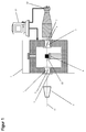
- Fig. 1 shows a device according to the invention for the thermo-optical examination of samples.
- the device contains a climatic cabinet 1 with two viewing openings arranged on opposite sides of the climatic cabinet.
- the first view port is with a first sight vacuum flange 2 sealed vacuum-tight.
- the first visual vacuum flange 2 has two opposing viewing windows 4, 5 and a vacuum-tight interior arranged between these two viewing windows 4, 5.
- the second view opening is closed in a vacuum-tight manner with a second view vacuum flange 3, the second view vacuum flange 3 having two viewing windows 6, 7 opposite one another and a vacuum-tight interior arranged between these two viewing windows 6, 7.
- the apparatus also includes a sample tray 8 disposed within the climatic cabinet 1 between the visual vacuum flanges 2 and 3, a light source 9, and a light detector 10.
- the light source 9 is a high power LED.
- the light detector 10 is a CMOS camera.
- the light source 9 and the light detector 10 are arranged outside of the climatic cabinet 1 so that an extending from the light source 9 to the light detector 10 optical viewing axis 11 through the two viewing windows 4, 5, 6, 7 of the two submitvakuumflansche 2, 3 and through a the sample tray 8 arranged sample 12 extends.
- the light detector 10 is connected to a device for software-based evaluation 13, wherein this device is a computer.
Landscapes
- Physics & Mathematics (AREA)
- Health & Medical Sciences (AREA)
- Life Sciences & Earth Sciences (AREA)
- Chemical & Material Sciences (AREA)
- Analytical Chemistry (AREA)
- Biochemistry (AREA)
- General Health & Medical Sciences (AREA)
- General Physics & Mathematics (AREA)
- Immunology (AREA)
- Pathology (AREA)
- Investigating Or Analyzing Materials Using Thermal Means (AREA)
Applications Claiming Priority (1)
| Application Number | Priority Date | Filing Date | Title |
|---|---|---|---|
| DE102015214292.2A DE102015214292A1 (de) | 2015-07-28 | 2015-07-28 | Vorrichtung und Verfahren zur thermo-optischen Untersuchung von Proben |
Publications (3)
| Publication Number | Publication Date |
|---|---|
| EP3133384A2 true EP3133384A2 (fr) | 2017-02-22 |
| EP3133384A3 EP3133384A3 (fr) | 2017-05-17 |
| EP3133384B1 EP3133384B1 (fr) | 2019-09-04 |
Family
ID=56555246
Family Applications (1)
| Application Number | Title | Priority Date | Filing Date |
|---|---|---|---|
| EP16181543.6A Active EP3133384B1 (fr) | 2015-07-28 | 2016-07-27 | Dispositif et procede de recherche thermo-optique d'echantillons |
Country Status (2)
| Country | Link |
|---|---|
| EP (1) | EP3133384B1 (fr) |
| DE (1) | DE102015214292A1 (fr) |
Cited By (1)
| Publication number | Priority date | Publication date | Assignee | Title |
|---|---|---|---|---|
| CN114671055A (zh) * | 2022-03-24 | 2022-06-28 | 中国科学院国家空间科学中心 | 一种月面综合环境下摩擦带电的地面模拟实验装置及方法 |
Families Citing this family (2)
| Publication number | Priority date | Publication date | Assignee | Title |
|---|---|---|---|---|
| DE102021118888B4 (de) | 2021-07-21 | 2023-04-13 | Hochschule Koblenz, Körperschaft des öffentlichen Rechts | Vorrichtung und Verfahren zur Ermittlung der Temperaturwechselbeständigkeit eines Prüfkörpers |
| CN114791514A (zh) * | 2022-04-01 | 2022-07-26 | 上海科技大学 | 一种超高真空原位滴水装置 |
Family Cites Families (17)
| Publication number | Priority date | Publication date | Assignee | Title |
|---|---|---|---|---|
| GB1144408A (en) * | 1967-03-08 | 1969-03-05 | Akad Wissenschaften Ddr | Improvements in or relating to temperature controllable cuvettes for spectroscopic examinations |
| DE1598468B2 (de) * | 1967-08-07 | 1976-08-19 | Bayer Ag, 5090 Leverkusen | Verfahren und vorrichtung zur kurzbewitterung pigmentierter bindemittelsysteme |
| US4429999A (en) * | 1981-06-22 | 1984-02-07 | Bimberg Dieter H | Method for calorimetric absorption spectroscopy and device for working the method |
| DE3741429A1 (de) * | 1987-12-08 | 1989-06-22 | Zwick Gmbh & Co | Vorrichtung zur durchfuehrung von werkstoffpruefungen |
| US5386731A (en) * | 1990-09-07 | 1995-02-07 | Southern Research Institute | Method and apparatus for measuring the tensile strength of powders |
| US5463460A (en) * | 1993-07-08 | 1995-10-31 | Applied Materials, Inc. | Particle monitoring sensor |
| DE19601788C1 (de) * | 1996-01-19 | 1997-07-24 | Geesthacht Gkss Forschung | Vorrichtung zur berührungslosen Erfassung von Bruchparametern bei einer Hochtemperaturwerkstoffprüfung |
| CN2314365Y (zh) * | 1997-12-27 | 1999-04-14 | 中国科学院长春物理研究所 | 半导体光学测量真空辅助低温装置 |
| US6711941B2 (en) * | 2000-08-14 | 2004-03-30 | Cambridge Polymer Group, Inc. | Apparatus and methods for measuring extensional rheological properties of a material |
| JP2003322611A (ja) * | 2002-04-30 | 2003-11-14 | Horiba Ltd | 光学窓を備える測定室 |
| JP2003077969A (ja) * | 2002-05-31 | 2003-03-14 | Hitachi Ltd | 異物検出方法とその装置並びに半導体装置製造方法 |
| DE10303736B4 (de) * | 2003-01-30 | 2007-05-10 | Thermo Electron Led Gmbh | Klimaschrank und insbesondere Klimakühlschrank |
| DE102010019776B4 (de) * | 2010-05-07 | 2015-07-02 | Thermo Electron Led Gmbh | Klimaschrank mit mehreren Ein- und Ausgabestationen |
| DE102011055953B3 (de) * | 2011-12-01 | 2013-04-18 | Fachhochschule Schmalkalden | Verfahren und Prüfanordnung zur Werkstoffprüfung |
| JPWO2013157217A1 (ja) * | 2012-04-19 | 2015-12-21 | パナソニック株式会社 | 水分量変動検知装置、水分量変動検知方法、真空計及び真空度変動検知方法 |
| EP2662648B1 (fr) * | 2012-05-10 | 2019-05-01 | Miele & Cie. KG | Armoire climatique ou réfrigérante |
| CN203037568U (zh) * | 2012-09-18 | 2013-07-03 | 中国石油天然气股份有限公司 | 一种双试样红外透射池 |
-
2015
- 2015-07-28 DE DE102015214292.2A patent/DE102015214292A1/de not_active Ceased
-
2016
- 2016-07-27 EP EP16181543.6A patent/EP3133384B1/fr active Active
Non-Patent Citations (1)
| Title |
|---|
| None |
Cited By (2)
| Publication number | Priority date | Publication date | Assignee | Title |
|---|---|---|---|---|
| CN114671055A (zh) * | 2022-03-24 | 2022-06-28 | 中国科学院国家空间科学中心 | 一种月面综合环境下摩擦带电的地面模拟实验装置及方法 |
| CN114671055B (zh) * | 2022-03-24 | 2023-02-07 | 中国科学院国家空间科学中心 | 一种月面综合环境下摩擦带电的地面模拟实验装置及方法 |
Also Published As
| Publication number | Publication date |
|---|---|
| EP3133384A3 (fr) | 2017-05-17 |
| EP3133384B1 (fr) | 2019-09-04 |
| DE102015214292A1 (de) | 2017-02-02 |
Similar Documents
| Publication | Publication Date | Title |
|---|---|---|
| DE102011055953B3 (de) | Verfahren und Prüfanordnung zur Werkstoffprüfung | |
| DE69227146T2 (de) | Gerät und Verfahren zur Beobachtung einer dreidimensionalen Anordnung von Atomen | |
| EP1145303A1 (fr) | Dispositif et procede de controle optique de processus de fabrication de surfaces microstructurees dans la production de semi-conducteurs | |
| DE102012105101B3 (de) | Thermoanalysevorrichtung | |
| DE102015221697B3 (de) | Anordnung zur Bestimmung der Oberflächenbeschaffenheit von Bauteiloberflächen | |
| EP3133384B1 (fr) | Dispositif et procede de recherche thermo-optique d'echantillons | |
| WO2009118199A1 (fr) | Procédé d'essai thermographique de matériaux non métalliques, en particulier de matériaux non métalliques revêtus, ainsi que leur procédé de fabrication, et objets fabriqués selon ce procédé | |
| DE102011111836A1 (de) | Vorrichtung und Verfahren zur Kältemittelidentifikation | |
| DE102013102659B4 (de) | Proben-Vorbereitungseinrichtung und Proben-Vorbereitungsverfahren | |
| EP4143520A1 (fr) | Pluralité de spectromètres à structure identique et procédé associé d'étalonnage | |
| DE102011111613B4 (de) | Sensoranordnung zur Charakterisierung von Plasmabeschichtungs-, Plasmaätz- und Plasmabehandlungsprozessen sowie Verfahren zur Ermittlung von Kenngrößen in diesen Prozessen | |
| DE19922614A1 (de) | Verfahren und Vorrichtung zur optischen Kontrolle von Fertigungsprozessen feinstrukturierter Oberflächen in der Halbleiterfertigung | |
| EP3739321B1 (fr) | Procédé de qualification pour échantillons de microscopie cryoélectrique ainsi que porte-échantillon associé | |
| EP3158322A1 (fr) | Dispositif et procédé d'étalonnage d'un appareil de mesure de lumière diffuse | |
| WO2008046588A1 (fr) | procédé de quantification de l'activité photocatalytique de surfaces et utilisation du procédé | |
| DE102014222483B4 (de) | Verfahren zur Analyse eines anhaftenden Oberflächenfilms auf einem Prüfling | |
| DE102010023655A1 (de) | Verfahren zur automatisierten Beurteilung von Korrosionsschäden nach zerstörungsfreier Prüfung mittels Impulsthermographie | |
| DE102015200648A1 (de) | Verfahren zur Bestimmung des Vernetzungsgrads einer Polyethylenverbindung | |
| DE102017221210A1 (de) | Verfahren und Vorrichtung zur kontinuierlichen Überwachung von Stoffen sowie zugehöriges Computerprogrammprodukt und computerlesbares Medium | |
| EP3244186A1 (fr) | Chambre de controle et procede destines a mesurer la temperature de produit de test dans une chambre de controle | |
| DE102005054552B4 (de) | Vorrichtung und Verfahren zur Prüfung von Halbleitersubstraten auf Risse | |
| Titus et al. | Impedance Spectroscopy for Quality Testing of Interdigitated Circuits. | |
| AT526886A1 (de) | Spektrometer mit automatischer Kalibrierung | |
| DE102008017973B4 (de) | Verfahren und Vorrichtung zur Bestimmung von Diffusionskoeffizienten | |
| DE202014105158U1 (de) | Vorrichtung zur Elementaranalyse an Mikroskopen |
Legal Events
| Date | Code | Title | Description |
|---|---|---|---|
| PUAI | Public reference made under article 153(3) epc to a published international application that has entered the european phase |
Free format text: ORIGINAL CODE: 0009012 |
|
| STAA | Information on the status of an ep patent application or granted ep patent |
Free format text: STATUS: THE APPLICATION HAS BEEN PUBLISHED |
|
| AK | Designated contracting states |
Kind code of ref document: A2 Designated state(s): AL AT BE BG CH CY CZ DE DK EE ES FI FR GB GR HR HU IE IS IT LI LT LU LV MC MK MT NL NO PL PT RO RS SE SI SK SM TR |
|
| AX | Request for extension of the european patent |
Extension state: BA ME |
|
| PUAL | Search report despatched |
Free format text: ORIGINAL CODE: 0009013 |
|
| AK | Designated contracting states |
Kind code of ref document: A3 Designated state(s): AL AT BE BG CH CY CZ DE DK EE ES FI FR GB GR HR HU IE IS IT LI LT LU LV MC MK MT NL NO PL PT RO RS SE SI SK SM TR |
|
| AX | Request for extension of the european patent |
Extension state: BA ME |
|
| RIC1 | Information provided on ipc code assigned before grant |
Ipc: G01N 21/15 20060101ALI20170412BHEP Ipc: G01N 21/03 20060101ALI20170412BHEP Ipc: G01N 21/01 20060101AFI20170412BHEP |
|
| STAA | Information on the status of an ep patent application or granted ep patent |
Free format text: STATUS: REQUEST FOR EXAMINATION WAS MADE |
|
| 17P | Request for examination filed |
Effective date: 20171108 |
|
| RBV | Designated contracting states (corrected) |
Designated state(s): AL AT BE BG CH CY CZ DE DK EE ES FI FR GB GR HR HU IE IS IT LI LT LU LV MC MK MT NL NO PL PT RO RS SE SI SK SM TR |
|
| STAA | Information on the status of an ep patent application or granted ep patent |
Free format text: STATUS: EXAMINATION IS IN PROGRESS |
|
| 17Q | First examination report despatched |
Effective date: 20180808 |
|
| GRAP | Despatch of communication of intention to grant a patent |
Free format text: ORIGINAL CODE: EPIDOSNIGR1 |
|
| STAA | Information on the status of an ep patent application or granted ep patent |
Free format text: STATUS: GRANT OF PATENT IS INTENDED |
|
| INTG | Intention to grant announced |
Effective date: 20190423 |
|
| GRAS | Grant fee paid |
Free format text: ORIGINAL CODE: EPIDOSNIGR3 |
|
| GRAA | (expected) grant |
Free format text: ORIGINAL CODE: 0009210 |
|
| STAA | Information on the status of an ep patent application or granted ep patent |
Free format text: STATUS: THE PATENT HAS BEEN GRANTED |
|
| AK | Designated contracting states |
Kind code of ref document: B1 Designated state(s): AL AT BE BG CH CY CZ DE DK EE ES FI FR GB GR HR HU IE IS IT LI LT LU LV MC MK MT NL NO PL PT RO RS SE SI SK SM TR |
|
| REG | Reference to a national code |
Ref country code: GB Ref legal event code: FG4D Free format text: NOT ENGLISH |
|
| REG | Reference to a national code |
Ref country code: CH Ref legal event code: EP |
|
| REG | Reference to a national code |
Ref country code: AT Ref legal event code: REF Ref document number: 1176056 Country of ref document: AT Kind code of ref document: T Effective date: 20190915 |
|
| REG | Reference to a national code |
Ref country code: DE Ref legal event code: R096 Ref document number: 502016006390 Country of ref document: DE |
|
| REG | Reference to a national code |
Ref country code: IE Ref legal event code: FG4D Free format text: LANGUAGE OF EP DOCUMENT: GERMAN |
|
| REG | Reference to a national code |
Ref country code: NL Ref legal event code: MP Effective date: 20190904 |
|
| REG | Reference to a national code |
Ref country code: LT Ref legal event code: MG4D |
|
| PG25 | Lapsed in a contracting state [announced via postgrant information from national office to epo] |
Ref country code: FI Free format text: LAPSE BECAUSE OF FAILURE TO SUBMIT A TRANSLATION OF THE DESCRIPTION OR TO PAY THE FEE WITHIN THE PRESCRIBED TIME-LIMIT Effective date: 20190904 Ref country code: LT Free format text: LAPSE BECAUSE OF FAILURE TO SUBMIT A TRANSLATION OF THE DESCRIPTION OR TO PAY THE FEE WITHIN THE PRESCRIBED TIME-LIMIT Effective date: 20190904 Ref country code: BG Free format text: LAPSE BECAUSE OF FAILURE TO SUBMIT A TRANSLATION OF THE DESCRIPTION OR TO PAY THE FEE WITHIN THE PRESCRIBED TIME-LIMIT Effective date: 20191204 Ref country code: NO Free format text: LAPSE BECAUSE OF FAILURE TO SUBMIT A TRANSLATION OF THE DESCRIPTION OR TO PAY THE FEE WITHIN THE PRESCRIBED TIME-LIMIT Effective date: 20191204 Ref country code: SE Free format text: LAPSE BECAUSE OF FAILURE TO SUBMIT A TRANSLATION OF THE DESCRIPTION OR TO PAY THE FEE WITHIN THE PRESCRIBED TIME-LIMIT Effective date: 20190904 Ref country code: HR Free format text: LAPSE BECAUSE OF FAILURE TO SUBMIT A TRANSLATION OF THE DESCRIPTION OR TO PAY THE FEE WITHIN THE PRESCRIBED TIME-LIMIT Effective date: 20190904 |
|
| PG25 | Lapsed in a contracting state [announced via postgrant information from national office to epo] |
Ref country code: LV Free format text: LAPSE BECAUSE OF FAILURE TO SUBMIT A TRANSLATION OF THE DESCRIPTION OR TO PAY THE FEE WITHIN THE PRESCRIBED TIME-LIMIT Effective date: 20190904 Ref country code: RS Free format text: LAPSE BECAUSE OF FAILURE TO SUBMIT A TRANSLATION OF THE DESCRIPTION OR TO PAY THE FEE WITHIN THE PRESCRIBED TIME-LIMIT Effective date: 20190904 Ref country code: GR Free format text: LAPSE BECAUSE OF FAILURE TO SUBMIT A TRANSLATION OF THE DESCRIPTION OR TO PAY THE FEE WITHIN THE PRESCRIBED TIME-LIMIT Effective date: 20191205 Ref country code: AL Free format text: LAPSE BECAUSE OF FAILURE TO SUBMIT A TRANSLATION OF THE DESCRIPTION OR TO PAY THE FEE WITHIN THE PRESCRIBED TIME-LIMIT Effective date: 20190904 Ref country code: ES Free format text: LAPSE BECAUSE OF FAILURE TO SUBMIT A TRANSLATION OF THE DESCRIPTION OR TO PAY THE FEE WITHIN THE PRESCRIBED TIME-LIMIT Effective date: 20190904 |
|
| PG25 | Lapsed in a contracting state [announced via postgrant information from national office to epo] |
Ref country code: EE Free format text: LAPSE BECAUSE OF FAILURE TO SUBMIT A TRANSLATION OF THE DESCRIPTION OR TO PAY THE FEE WITHIN THE PRESCRIBED TIME-LIMIT Effective date: 20190904 Ref country code: PL Free format text: LAPSE BECAUSE OF FAILURE TO SUBMIT A TRANSLATION OF THE DESCRIPTION OR TO PAY THE FEE WITHIN THE PRESCRIBED TIME-LIMIT Effective date: 20190904 Ref country code: PT Free format text: LAPSE BECAUSE OF FAILURE TO SUBMIT A TRANSLATION OF THE DESCRIPTION OR TO PAY THE FEE WITHIN THE PRESCRIBED TIME-LIMIT Effective date: 20200106 Ref country code: IT Free format text: LAPSE BECAUSE OF FAILURE TO SUBMIT A TRANSLATION OF THE DESCRIPTION OR TO PAY THE FEE WITHIN THE PRESCRIBED TIME-LIMIT Effective date: 20190904 Ref country code: NL Free format text: LAPSE BECAUSE OF FAILURE TO SUBMIT A TRANSLATION OF THE DESCRIPTION OR TO PAY THE FEE WITHIN THE PRESCRIBED TIME-LIMIT Effective date: 20190904 Ref country code: RO Free format text: LAPSE BECAUSE OF FAILURE TO SUBMIT A TRANSLATION OF THE DESCRIPTION OR TO PAY THE FEE WITHIN THE PRESCRIBED TIME-LIMIT Effective date: 20190904 |
|
| PG25 | Lapsed in a contracting state [announced via postgrant information from national office to epo] |
Ref country code: SM Free format text: LAPSE BECAUSE OF FAILURE TO SUBMIT A TRANSLATION OF THE DESCRIPTION OR TO PAY THE FEE WITHIN THE PRESCRIBED TIME-LIMIT Effective date: 20190904 Ref country code: SK Free format text: LAPSE BECAUSE OF FAILURE TO SUBMIT A TRANSLATION OF THE DESCRIPTION OR TO PAY THE FEE WITHIN THE PRESCRIBED TIME-LIMIT Effective date: 20190904 Ref country code: CZ Free format text: LAPSE BECAUSE OF FAILURE TO SUBMIT A TRANSLATION OF THE DESCRIPTION OR TO PAY THE FEE WITHIN THE PRESCRIBED TIME-LIMIT Effective date: 20190904 Ref country code: IS Free format text: LAPSE BECAUSE OF FAILURE TO SUBMIT A TRANSLATION OF THE DESCRIPTION OR TO PAY THE FEE WITHIN THE PRESCRIBED TIME-LIMIT Effective date: 20200224 |
|
| REG | Reference to a national code |
Ref country code: DE Ref legal event code: R097 Ref document number: 502016006390 Country of ref document: DE |
|
| PLBE | No opposition filed within time limit |
Free format text: ORIGINAL CODE: 0009261 |
|
| STAA | Information on the status of an ep patent application or granted ep patent |
Free format text: STATUS: NO OPPOSITION FILED WITHIN TIME LIMIT |
|
| PG2D | Information on lapse in contracting state deleted |
Ref country code: IS |
|
| PG25 | Lapsed in a contracting state [announced via postgrant information from national office to epo] |
Ref country code: DK Free format text: LAPSE BECAUSE OF FAILURE TO SUBMIT A TRANSLATION OF THE DESCRIPTION OR TO PAY THE FEE WITHIN THE PRESCRIBED TIME-LIMIT Effective date: 20190904 Ref country code: IS Free format text: LAPSE BECAUSE OF FAILURE TO SUBMIT A TRANSLATION OF THE DESCRIPTION OR TO PAY THE FEE WITHIN THE PRESCRIBED TIME-LIMIT Effective date: 20200105 |
|
| 26N | No opposition filed |
Effective date: 20200605 |
|
| PG25 | Lapsed in a contracting state [announced via postgrant information from national office to epo] |
Ref country code: SI Free format text: LAPSE BECAUSE OF FAILURE TO SUBMIT A TRANSLATION OF THE DESCRIPTION OR TO PAY THE FEE WITHIN THE PRESCRIBED TIME-LIMIT Effective date: 20190904 |
|
| PG25 | Lapsed in a contracting state [announced via postgrant information from national office to epo] |
Ref country code: MC Free format text: LAPSE BECAUSE OF FAILURE TO SUBMIT A TRANSLATION OF THE DESCRIPTION OR TO PAY THE FEE WITHIN THE PRESCRIBED TIME-LIMIT Effective date: 20190904 |
|
| GBPC | Gb: european patent ceased through non-payment of renewal fee |
Effective date: 20200727 |
|
| REG | Reference to a national code |
Ref country code: BE Ref legal event code: MM Effective date: 20200731 |
|
| PG25 | Lapsed in a contracting state [announced via postgrant information from national office to epo] |
Ref country code: LU Free format text: LAPSE BECAUSE OF NON-PAYMENT OF DUE FEES Effective date: 20200727 Ref country code: FR Free format text: LAPSE BECAUSE OF NON-PAYMENT OF DUE FEES Effective date: 20200731 Ref country code: GB Free format text: LAPSE BECAUSE OF NON-PAYMENT OF DUE FEES Effective date: 20200727 |
|
| PG25 | Lapsed in a contracting state [announced via postgrant information from national office to epo] |
Ref country code: BE Free format text: LAPSE BECAUSE OF NON-PAYMENT OF DUE FEES Effective date: 20200731 |
|
| PG25 | Lapsed in a contracting state [announced via postgrant information from national office to epo] |
Ref country code: IE Free format text: LAPSE BECAUSE OF NON-PAYMENT OF DUE FEES Effective date: 20200727 |
|
| PG25 | Lapsed in a contracting state [announced via postgrant information from national office to epo] |
Ref country code: TR Free format text: LAPSE BECAUSE OF FAILURE TO SUBMIT A TRANSLATION OF THE DESCRIPTION OR TO PAY THE FEE WITHIN THE PRESCRIBED TIME-LIMIT Effective date: 20190904 Ref country code: MT Free format text: LAPSE BECAUSE OF FAILURE TO SUBMIT A TRANSLATION OF THE DESCRIPTION OR TO PAY THE FEE WITHIN THE PRESCRIBED TIME-LIMIT Effective date: 20190904 Ref country code: CY Free format text: LAPSE BECAUSE OF FAILURE TO SUBMIT A TRANSLATION OF THE DESCRIPTION OR TO PAY THE FEE WITHIN THE PRESCRIBED TIME-LIMIT Effective date: 20190904 |
|
| PG25 | Lapsed in a contracting state [announced via postgrant information from national office to epo] |
Ref country code: MK Free format text: LAPSE BECAUSE OF FAILURE TO SUBMIT A TRANSLATION OF THE DESCRIPTION OR TO PAY THE FEE WITHIN THE PRESCRIBED TIME-LIMIT Effective date: 20190904 |
|
| P01 | Opt-out of the competence of the unified patent court (upc) registered |
Effective date: 20230524 |
|
| PGFP | Annual fee paid to national office [announced via postgrant information from national office to epo] |
Ref country code: DE Payment date: 20250722 Year of fee payment: 10 |
|
| PGFP | Annual fee paid to national office [announced via postgrant information from national office to epo] |
Ref country code: AT Payment date: 20250721 Year of fee payment: 10 |
|
| PGFP | Annual fee paid to national office [announced via postgrant information from national office to epo] |
Ref country code: CH Payment date: 20250801 Year of fee payment: 10 |