EP3134263B1 - Ligne de production pour la fabrication de produits d'impression - Google Patents
Ligne de production pour la fabrication de produits d'impression Download PDFInfo
- Publication number
- EP3134263B1 EP3134263B1 EP15710449.8A EP15710449A EP3134263B1 EP 3134263 B1 EP3134263 B1 EP 3134263B1 EP 15710449 A EP15710449 A EP 15710449A EP 3134263 B1 EP3134263 B1 EP 3134263B1
- Authority
- EP
- European Patent Office
- Prior art keywords
- printing
- section
- folding
- printing material
- cross
- Prior art date
- Legal status (The legal status is an assumption and is not a legal conclusion. Google has not performed a legal analysis and makes no representation as to the accuracy of the status listed.)
- Active
Links
Images












Classifications
-
- B—PERFORMING OPERATIONS; TRANSPORTING
- B41—PRINTING; LINING MACHINES; TYPEWRITERS; STAMPS
- B41J—TYPEWRITERS; SELECTIVE PRINTING MECHANISMS, i.e. MECHANISMS PRINTING OTHERWISE THAN FROM A FORME; CORRECTION OF TYPOGRAPHICAL ERRORS
- B41J13/00—Devices or arrangements of selective printing mechanisms, e.g. ink-jet printers or thermal printers, specially adapted for supporting or handling copy material in short lengths, e.g. sheets
- B41J13/10—Sheet holders, retainers, movable guides, or stationary guides
- B41J13/22—Clamps or grippers
- B41J13/223—Clamps or grippers on rotatable drums
-
- B—PERFORMING OPERATIONS; TRANSPORTING
- B65—CONVEYING; PACKING; STORING; HANDLING THIN OR FILAMENTARY MATERIAL
- B65H—HANDLING THIN OR FILAMENTARY MATERIAL, e.g. SHEETS, WEBS, CABLES
- B65H37/00—Article or web delivery apparatus incorporating devices for performing specified auxiliary operations
- B65H37/04—Article or web delivery apparatus incorporating devices for performing specified auxiliary operations for securing together articles or webs, e.g. by adhesive, stitching or stapling
-
- B—PERFORMING OPERATIONS; TRANSPORTING
- B41—PRINTING; LINING MACHINES; TYPEWRITERS; STAMPS
- B41F—PRINTING MACHINES OR PRESSES
- B41F13/00—Common details of rotary presses or machines
- B41F13/54—Auxiliary folding, cutting, collecting or depositing of sheets or webs
- B41F13/56—Folding or cutting
- B41F13/58—Folding or cutting lengthwise
-
- B—PERFORMING OPERATIONS; TRANSPORTING
- B41—PRINTING; LINING MACHINES; TYPEWRITERS; STAMPS
- B41F—PRINTING MACHINES OR PRESSES
- B41F13/00—Common details of rotary presses or machines
- B41F13/54—Auxiliary folding, cutting, collecting or depositing of sheets or webs
- B41F13/56—Folding or cutting
- B41F13/60—Folding or cutting crosswise
-
- B—PERFORMING OPERATIONS; TRANSPORTING
- B41—PRINTING; LINING MACHINES; TYPEWRITERS; STAMPS
- B41F—PRINTING MACHINES OR PRESSES
- B41F13/00—Common details of rotary presses or machines
- B41F13/54—Auxiliary folding, cutting, collecting or depositing of sheets or webs
- B41F13/64—Collecting
- B41F13/66—Collecting and stapling
-
- B—PERFORMING OPERATIONS; TRANSPORTING
- B41—PRINTING; LINING MACHINES; TYPEWRITERS; STAMPS
- B41J—TYPEWRITERS; SELECTIVE PRINTING MECHANISMS, i.e. MECHANISMS PRINTING OTHERWISE THAN FROM A FORME; CORRECTION OF TYPOGRAPHICAL ERRORS
- B41J13/00—Devices or arrangements of selective printing mechanisms, e.g. ink-jet printers or thermal printers, specially adapted for supporting or handling copy material in short lengths, e.g. sheets
- B41J13/0009—Devices or arrangements of selective printing mechanisms, e.g. ink-jet printers or thermal printers, specially adapted for supporting or handling copy material in short lengths, e.g. sheets control of the transport of the copy material
- B41J13/0036—Devices or arrangements of selective printing mechanisms, e.g. ink-jet printers or thermal printers, specially adapted for supporting or handling copy material in short lengths, e.g. sheets control of the transport of the copy material in the output section of automatic paper handling systems
-
- B—PERFORMING OPERATIONS; TRANSPORTING
- B41—PRINTING; LINING MACHINES; TYPEWRITERS; STAMPS
- B41J—TYPEWRITERS; SELECTIVE PRINTING MECHANISMS, i.e. MECHANISMS PRINTING OTHERWISE THAN FROM A FORME; CORRECTION OF TYPOGRAPHICAL ERRORS
- B41J13/00—Devices or arrangements of selective printing mechanisms, e.g. ink-jet printers or thermal printers, specially adapted for supporting or handling copy material in short lengths, e.g. sheets
- B41J13/10—Sheet holders, retainers, movable guides, or stationary guides
- B41J13/106—Sheet holders, retainers, movable guides, or stationary guides for the sheet output section
-
- B—PERFORMING OPERATIONS; TRANSPORTING
- B41—PRINTING; LINING MACHINES; TYPEWRITERS; STAMPS
- B41J—TYPEWRITERS; SELECTIVE PRINTING MECHANISMS, i.e. MECHANISMS PRINTING OTHERWISE THAN FROM A FORME; CORRECTION OF TYPOGRAPHICAL ERRORS
- B41J2/00—Typewriters or selective printing mechanisms characterised by the printing or marking process for which they are designed
- B41J2/005—Typewriters or selective printing mechanisms characterised by the printing or marking process for which they are designed characterised by bringing liquid or particles selectively into contact with a printing material
- B41J2/01—Ink jet
-
- B—PERFORMING OPERATIONS; TRANSPORTING
- B42—BOOKBINDING; ALBUMS; FILES; SPECIAL PRINTED MATTER
- B42B—PERMANENTLY ATTACHING TOGETHER SHEETS, QUIRES OR SIGNATURES OR PERMANENTLY ATTACHING OBJECTS THERETO
- B42B4/00—Permanently attaching together sheets, quires or signatures by discontinuous stitching with filamentary material, e.g. wire
-
- B—PERFORMING OPERATIONS; TRANSPORTING
- B42—BOOKBINDING; ALBUMS; FILES; SPECIAL PRINTED MATTER
- B42C—BOOKBINDING
- B42C1/00—Collating or gathering sheets combined with processes for permanently attaching together sheets or signatures or for interposing inserts
- B42C1/12—Machines for both collating or gathering and permanently attaching together the sheets or signatures
-
- B—PERFORMING OPERATIONS; TRANSPORTING
- B65—CONVEYING; PACKING; STORING; HANDLING THIN OR FILAMENTARY MATERIAL
- B65H—HANDLING THIN OR FILAMENTARY MATERIAL, e.g. SHEETS, WEBS, CABLES
- B65H45/00—Folding thin material
- B65H45/12—Folding articles or webs with application of pressure to define or form crease lines
- B65H45/16—Rotary folders
- B65H45/162—Rotary folders with folding jaw cylinders
-
- G—PHYSICS
- G03—PHOTOGRAPHY; CINEMATOGRAPHY; ANALOGOUS TECHNIQUES USING WAVES OTHER THAN OPTICAL WAVES; ELECTROGRAPHY; HOLOGRAPHY
- G03G—ELECTROGRAPHY; ELECTROPHOTOGRAPHY; MAGNETOGRAPHY
- G03G15/00—Apparatus for electrographic processes using a charge pattern
- G03G15/65—Apparatus which relate to the handling of copy material
- G03G15/6538—Devices for collating sheet copy material, e.g. sorters, control, copies in staples form
- G03G15/6541—Binding sets of sheets, e.g. by stapling, glueing
- G03G15/6544—Details about the binding means or procedure
-
- B—PERFORMING OPERATIONS; TRANSPORTING
- B65—CONVEYING; PACKING; STORING; HANDLING THIN OR FILAMENTARY MATERIAL
- B65H—HANDLING THIN OR FILAMENTARY MATERIAL, e.g. SHEETS, WEBS, CABLES
- B65H2701/00—Handled material; Storage means
- B65H2701/10—Handled articles or webs
- B65H2701/18—Form of handled article or web
- B65H2701/182—Piled package
- B65H2701/18271—Piled package of folded sheet material
-
- B—PERFORMING OPERATIONS; TRANSPORTING
- B65—CONVEYING; PACKING; STORING; HANDLING THIN OR FILAMENTARY MATERIAL
- B65H—HANDLING THIN OR FILAMENTARY MATERIAL, e.g. SHEETS, WEBS, CABLES
- B65H2701/00—Handled material; Storage means
- B65H2701/10—Handled articles or webs
- B65H2701/19—Specific article or web
Definitions
- the invention relates to a production line with a printing press and a further processing section downstream of the printing press in the printing material path, according to the preamble of claim 1.
- a printing press which has at least one printing unit and at least one printing head designed as an inkjet printing head.
- the EP 2 305 466 A1 discloses a variable-format web printing press which has an inkjet device in one embodiment.
- the one or the last printing unit is followed by further processing in the printing material path, possibly with a turning device, at least one cutting device and folding former.
- Both the printing units and at least one actuating means of the at least one cutting device are in signal connection with a control device for actuation thereof.
- the further processing includes e.g. B. several in the direction of a paper web in series or parallel to each other folding devices.
- the DE 100 60 758 A1 relates to a cutting device in a folder of a web-fed rotary printing press, which is designed for cutting signatures with a variable section length.
- the DE 103 25 362 A1 relates to a method and an apparatus for indirect digital printing of images on webs.
- the printed web can be wound up after printing or alternatively can be further processed by means of a cross cutter.
- the EP 1 911 583 A1 relates to a method for producing a printing product-bound high-performance printing process, which is individualized in at least two subsequent steps.
- EP 1 733 988 A1 discloses a method and an apparatus for the production of newspapers, in which, in one embodiment of a cross-cutting device downstream, a collecting station, a 90 ° change in the direction of movement on a subsequent conveying device, a transverse folding device, a longitudinal folding device, a longitudinal stitching device and a second collecting station for plugging into one another beforehand follow formed booklets.
- the DE 10 2013 203 469 B3 relates to a folding apparatus, a cross-cutting device being followed downstream by a first collecting cylinder and a second collecting cylinder and the latter by a folding jaw cylinder.
- the second collecting cylinder can interact with a stapling cylinder.
- a web with printed images printed by a digital printing machine can be fed to the folder.
- a method and an apparatus for producing printed products is disclosed, wherein a printing machine for variable-format printing, in particular a digital printing machine, further processing with a cross-cutting device, a collecting device, a cross-folding device comprising a folding jaw cylinder and a collator for stacking sections is provided.
- a movable embodiment of the holding means of the collecting device which are designed as pin needles, these can be withdrawn in a controlled manner.
- a broadsheet production it is possible to use a web with a width of two or more page heights, such a web being cut open lengthways in a longitudinal folding device and the partial webs being placed on top of one another before they are cut transversely in signatures.
- the DE 36 28 411 A1 relates to a variable folder with a collecting cylinder and a jaw cylinder.
- the DE 10 2012 208 840 A1 relates to an inkjet printing machine with a reel unwinding device, two inkjet printing units and post-processing or post-processing.
- the DE 10 2012 200 877 A1 discloses a web printing machine with a longitudinal stapling device downstream of a collecting cylinder and a folding jaw cylinder for inline stapling.
- the DE 10 2012 202 458 A1 relates to a stapling device in a web printing press, wherein a multilayer strand can be formed over one or more former and this can be processed inline into products in a folder after cross-cutting. If the printing machine is designed to apply several sheets in succession to the web and the folder is equipped for carrying out a collecting operation, several strand sections can be collected on one another before cross-folding.
- the object of the invention is to create a production line with a printing press and a further processing section downstream of the printing press in the printing material path.
- a production line comprises at least one printing press and a further processing section downstream of the printing press in the printing material path, the printing press comprising at least one printing unit, by means of which a web or sheet-shaped printing material can be printed on at least one of its sides in a printing formless printing process, and in Further processing section of the printing material can be processed into printed products.
- the web or sheet-shaped printing material on at least one of its sides - in contrast to z.
- B. only subordinate impression of additional information - with print images of printed pages of the product to be manufactured, for example in the relevant format, for. B. Newspaper, tabloid, book or special format, printing formless printing process printable.
- At least one transverse folding device and a collecting device are provided as a further processing stage.
- the further processing section as such or preferably as part of an above-mentioned production line in connection with an upstream, in particular printing press-free printing machine, in a preferred embodiment in the guide path of one or this processing section to be traversed by the printing material as a further processing stage, is a first in the guide path - preferably one in the collecting operation operable cylinders comprising - collecting device and downstream of this collecting device and in particular upstream of a preferably provided transverse folding device, a further collecting device as a further processing stage, by means of which bundles of printing material sections formed by the first collecting device can be collected into a bundle joint either directly or indirectly downstream of the first collecting device.
- This is preferably designed as a rotating body, in particular as a collecting cylinder.
- a device for connecting a plurality of layers in the guide path is connected to or arranged downstream of the downstream first collecting device in such a way that several or all of the printing material sections to be collected in a bundle in the first collecting device can be connected to one another before being picked up by the second collecting device .
- printed single-layer or multi-layer successive medium or immediate successive printing material sections can be in each case in a processing section of the further processing section to be traversed by the web sections - preferably on a cylinder that can be operated in collective operation several are combined in a bundle, several of these bundles in the guide path are combined to form a bundle joint in the middle or immediately downstream of the grouping, whereby this bundle joint in the guide path is combined to form a bundle joint in the guide path middle or immediately downstream of the grouping - in relation to an existing transport direction - can be folded across. Due to the preferred design as a collecting cylinder, there is a uniform and therefore trouble-free movement when collecting. Due to the preferred embodiment with a device for connecting several layers, connected booklets can be collected on one another and folded together.
- the further processing section in particular in a printing material guide section upstream of the cross-cutting, comprises at least one further processing stage in the guide path of the processing section to be traversed by the printing material, in particular a combining device, through which two strands are to be guided before reaching a cross-cutting device.
- the further processing section in which printing material supplied or supplied on the input side can be processed into printed products, can have at least one collecting device and one related to the printing material path in the guide path of a processing line to be traversed by the printing material downstream cross folding device comprise, by means of which upstream multi-page width intermediate products produced by at least one collection can be folded transversely with respect to the input-side transport direction of the transverse folding device.
- a cutting device is provided in the guide path downstream of the cross-fold device such that intermediate products which are cross-folded, multi-page wide and can be cut into several narrower intermediate or end products without having to go through a further folding process after cross-folding.
- a printing material present for example, as a printing material web or in the form of a sheet, can be provided in at least one printing unit in a non-impact printing process without printing, for. B. continuously with for example at least two printed pages across the transport direction next to each other, the z. B. at least two printed pages side by side printing material are fed to a further processing, for example two printing pages side by side comprehensive printing material in the case of web-shaped formation without first folding them by a cross cutting device first in z. B.
- the cross-sectioned web sections or printing sheet sections already present in the form of an arc downstream are folded individually or in groups as a section bundle by a folding device comprising a folding jaw cylinder transversely to the transport direction.
- a folding device comprising a folding jaw cylinder transversely to the transport direction.
- the individually or as collected and, if necessary, stapled section bundles are transversely folded web sections having at least two printed pages next to one another, after cross folding, cut into printed products which are viewed transversely to the transport direction, e.g. B. only have the printed image of a printed page.
- the further processing section as such or as Part of an above-mentioned production line in connection with an upstream, in particular printing form-free printing machine, in a further preferred embodiment in the guide path of the processing path to be covered by the printing material, as a further processing stage, comprise a diversion device through which several strands formed by printed webs and / or printed partial webs each comprise one - viewed in a projection in the horizontal plane - in the delivery direction present in the printing unit in a same direction - viewed in projection in the horizontal plane - for this purpose the delivery direction is angled by 90 °.
- At least one strand formed by a printed web and / or printed partial web can be moved from a conveying direction present in the printing unit in a projection direction into a horizontal plane viewed in projection into the horizontal plane, by 90 ° for this purpose angled conveying direction are diverted, this diverted strand individually or combined with one or more further diverted strands is fed directly or indirectly to a cross-cutting device and there cut transversely into single-layer or multi-layer printing material sections, and finally these downstream with or without further processing in one or more Processing stages can be designed and / or picked as products.
- a cross-stitching device which is set up and arranged or can be arranged in a printing material path in such a way as to staple successive sections of material to be stitched directly and indirectly along a plurality of stitching tracks running alongside one another in the printing material flow
- at least two relate to one the number and sequence of the stapling points to be provided for each section or bundle in the transverse direction include stapling tools assigned to the same stapling track, by means of which stapling means can be introduced into at least two successively or directly following sections of stapling material, based on the number and
- the sequence of the stapling points to be provided for each section or bundle in the transverse direction are indeed to be attributed to the same stapling track, but based on the specific lateral position in the stapling section to be stapled, they are not in the same alignment, but are offset from one another.
- a cross-stitching of multilayered staple material sections that follow one another in the middle and / or immediately following in a printing material flow can take place along a plurality of staple tracks viewed next to one another transversely to the conveying direction, stapling agents being introduced into at least two successively staple material sections directly or indirectly, and the to be stapled sections as multi-layer sections or as a bundle of sections, the cross-stitching of these at least two sections being carried out in such a way that the stapling means introduced in the transverse direction in relation to the number and sequence of each section of staple material are indeed to be attributed to the same stapling traces, but with reference to that The concrete lateral position in the section to be stapled does not lie in the same alignment but is offset from one another.
- a particularly advantageous production line comprises a printing press and a further processing section downstream of the printing press in the printing material path, wherein the printing press comprises at least one printing unit, by means of which a web or sheet-shaped printing material can be printed on at least one of its sides in a printing formless printing process with printed images of printed pages of a print product to be produced .
- a printed printing material can be processed into the printed products, the further processing section comprising a printing material guiding line, via which the printing material, under the action of one or more further processing steps provided in the printing material guiding line, is passed at an output in the form of single- or multi-layer printing material sections to a processing line which further processes the printing material sections will or can be, with the substrate guide route as a further processing stage at least a combination device in the guide path comprises at least two strands formed by webs or partial webs, through which the at least two strands can be guided to one another to form a multi-layer strand.
- the processing line comprises at least one collecting device, which has a collecting cylinder and through which single or multi-layer printing material sections can be collected to form a bundle or several bundles to form a bundle bundle, as well as a transverse folding device functionally arranged after the at least one collecting device, by means of which the at least one Bundle or bundle joints leaving the collecting device can be folded transversely with respect to the transport direction on the input side.
- the collecting device comprises holding means designed as a gripper or group of grippers, and a drive that controls the movement of the grippers or group of grippers is designed mechanically independently of a drive that drives the collecting device.
- a particularly advantageous production line comprises a printing press and a further processing section downstream of the printing press in the printing material path, the printing press comprising at least one printing unit, by means of which a web or sheet-shaped printing material is produced on at least one of its sides in a printing form-free printing process with print images of printing pages of a printing unit
- Printed products can be printed and in the further processing section the printed printing material can be processed into the printed products.
- a substrate guiding section comprised by the further processing section comprises at least one combining device, through which at least two strands can be guided to form a multi-layer strand, and a cross-cutting device for cross-cutting a single-layer or multi-layer strand.
- a processing line following the printing material guide line comprises in the guide path of a processing line to be run through as further processing stages at least one collecting device and a cross-folding device arranged downstream, a control device assigned to the further processing section is provided.
- the control device stands here as a control device to be assigned to the further processing section, both with an actuating or drive means for setting and / or presetting the further processing stage designed as a combining device and also - in particular for the transmission of presetting data and / or dynamic data representing the collecting sequence or the substrate feed a control means assigned to the collecting device, in particular its drive for the holding means, in signal connection.
- a preferred design of the printing press as a printing press working in the non-impact method makes it possible to design each individual printing product individually. As a result of the savings in the printing forms, even small and very short runs of printed products can be produced at low cost and / or - assuming appropriate further processing of the printed products - personalized printed products can be produced.
- z. B. at least one transverse folding device for folding sections or bundles of sections, and z. B. with at least one of the transverse folding device upstream in the printing material collecting device for collecting several sections or bundles of sections and / or in a collecting device downstream in the printing material path for collecting several sections and / or with two collecting devices provided in the printing material path, a large spectrum of products can already be produced inline.
- a particularly large variability and diversity can be achieved if, in addition to this, a stitching device, in particular a transverse stitching device and / or at least one longitudinal folding device, is added.
- a production line for the production of printed products comprises at least a first section, in particular designed as a printing press 001, in which or in which web-shaped printing material 002, e.g. B. as printing substrate 002 or 002 for short, or lumpy, z. B. sheet or plate-shaped substrate 002, z. B. for both the sheet and the plate-shaped design as printing sheet 002 or sheet 002 for short, can be printed and possibly conditioned before and / or after printing and one of the printing press 001 downstream in the production direction second section, z. B. a receiving section 003, in which the printed substrate 002 'only as a printed product to transportable bundles or further processed into products P and possibly subsequently combined as a product bundle.
- the first section of the production line in particular in the form of a printing press 001 and the second section, in particular in the form of a further processing section 003, can be controlled via a control and / or planning system 004.
- the printing press 001 can be designed as a printing press designed for any industrial printing of printing products, for example a printing press based on a printing form, such as B. one by a gravure printing process, one by a flexographic printing process, one by the offset process or one working in combination of several of the processes mentioned Printing machine 001 be formed.
- a printing press 001 it is designed - possibly at least among other things - as a printing press 001 operating according to a non-impact method, ie a printing formless printing method.
- a printing press 001 which operates solely according to the non-impact method or as a printing machine based on the above-mentioned printing form-based printing method and also according to the non-impact method working printing machine 001, e.g. B. as a "hybrid printing press” 001.
- the printing formless process can basically be designed as a direct and / or contactless inking of the printing material 002 or as an indirect and / or touching coloring of the printing material 002.
- a printing machine 001 is to be understood here as a machine printing a printing material with a printing fluid.
- printing fluid includes, in the foregoing and below, the fluids, such as, for example, in a finely structured form and / or not only over a large area, that are produced by the printing press or at least one printing unit of the printing press.
- printing ink is to be understood in the following, if not explicitly differentiated and named accordingly, in the sense of a liquid or at least flowable coloring fluid to be printed in the printing press, which not only refers to the colloquially more commonly referred to as “printing ink” associated higher-viscosity coloring fluids for use in rotary printing machines, but in addition to this higher-viscosity coloring fluids in particular also low-viscosity coloring fluids such as "inks”, in particular inkjet inks, but also powdered coloring fluids such as. B. toner.
- the higher viscosity dyes in particular also low viscosity dyes, e.g. B. both the higher viscosity inks and the so-called inks are preferably solutions or dispersions of at least one colorant in at least one solvent.
- Solvents are, for example, water and / or organic solvents.
- the low-viscosity printing inks, which are also referred to as inks preferably have no binder or relatively little binder, while the higher-viscosity printing inks preferably contain a relatively large amount of binder and more preferably further auxiliaries.
- the colorants contained can be pigments and / or dyes, pigments being insoluble in the application medium, while dyes are soluble in the application medium.
- the printed substrate 002 can be processed without further processing to form printed products, e.g. B. to stack of lumpy, in particular sheet or plate-shaped, printed products or to a large container of an intermediate product not yet divided into the further processable or usable units, e.g. B. to roll printed web-shaped printing material 002 'of a web-shaped printed product to summarize or commission.
- printed products e.g. B. to stack of lumpy, in particular sheet or plate-shaped, printed products or to a large container of an intermediate product not yet divided into the further processable or usable units, e.g. B. to roll printed web-shaped printing material 002 'of a web-shaped printed product to summarize or commission.
- the second section comprises a storage device 700 designed, for example, as a stack delivery, as a plano delivery with an upstream cross cutter or as a roll winder, to which the printed printing material 002 'can be fed inline from the output of the printing press 001 via a printing material guide path 500.
- the printing material guide section 500 arranged upstream of the storage device 700 can comprise means for longitudinal cutting in the event that a plurality of product pages or copies of products P can be printed on the printing material 002 side by side at the same time.
- the printing material 002 provided by the first section - preferably “inline” - can be fed to a receiving section 003 designed as a further processing section 003, where it is processed in one or preferably several handling and / or processing stages 502; 503; 504; 506; 507; 508; 509; 511; 512; 513; 521; 523; 601; 602; 603; 604; 606; 607; 608; 609; 611; 612 by corresponding Handling and / or processing devices for the print product P to be produced can be processed and / or processed.
- printed product P - unless explicitly or clearly implicitly recognizable in relation to a specific training - should be understood to mean a product P to be produced by production line 001, which product is both an end product for the end user and also a z. B. referred to as a section or book part of several such parts, for. B. sections or books, on and / or in each other comprehensive product or a downstream or in an independent work step further to an end product and / or to represent an intermediate or partial product or stack of sheets.
- “Inline” further processing means further processing in time with the stream of printed substrate 002 supplied by the printing press 001 and / or further processing following the preceding printing process without interruption in the material flow.
- a print shop can include a printing system with one or more such production lines.
- a plurality of printing machines 001 of a printing system can each be followed by one or at least one common or at least one further processing section 003 that can optionally be coupled to a first and / or a second printing machine 001 on the input side.
- the first section, in particular in the form of a printing press 001, and the second section, in particular in the form of a further processing section 003, of the production line can be controlled at least with regard to their basic functions by and / or a control means 800 of the control and / or planning system 004 called machine control 800.
- the printing press 001 comprises, for example, at least one substrate 100 and at least one printing unit 200; 400, to which the substrate 002 can be fed from the substrate 100.
- the at least one printing unit 200; 400 is preferably designed as a printing unit 200 operating according to a non-impact method and / or comprises at least one printing unit 211 operating according to a non-impact method; 411.
- the printing press 001 can only have one or more printing units 200; 400 or, in a variant, optionally additionally comprise one or more printing units operating according to another printing method.
- the printing unit 200 which operates according to a non-impact method; 400 or printing unit 211; 411 can, for example, be one using an electrophotographic method, one using an ionographic method, one using a magnetographic method, one using an inkjet method, one using a thermographic method or, if appropriate, one using one of the methods mentioned Printing unit 200 operating non-impact method; 400 or printing unit 211; 411.
- the printing press 001 can also use two or more according to different o.
- Printing units 200 operating non-impact method; 400 and / or printing units 211; 411 include.
- the printing press 001 can in this case be designed as a printing press 001 that works according to the inkjet or ink jet method — in particular or possibly in addition to other non-impact and / or printing form-based methods, in particular as an ink jet printing machine 001.
- a printing unit 200 which operates or can be operated in the inkjet or inkjet method; 400 and / or printing unit 211; 411 with a printing system designed as an inkjet system is the imaging device 212; 412 by one or more printheads 212; 412, e.g. B. a group of at least transverse to the local movement and / or conveying direction F; F 'of the substrate 002, e.g. B. substrate transport direction F; F 'or short transport direction F; F 'printheads 212; 412, the one or more of at least transverse to the substrate transport direction F; F 'include juxtaposed nozzles.
- a print head 212; which moves cyclically back and forth in the transverse direction; 412 may be provided.
- the imaging device 212; 412 can be formed by the spatially resolving exposure device, which is directed onto a photoconductor carrier and has, for example, a multiplicity of light sources and / or exposure points.
- the imaging elements preferably in large numbers (for example> 50 / cm, in particular> 100 / cm) arranged next to one another in the transverse direction or, if appropriate, cyclically moved back and forth in the transverse direction, eg. B. nozzles or light sources, the imaging device 212; 412 is in connection with a relative movement along the conveying direction F; F 'between imaging device 212; 412 and substrate 002 a print image can be generated.
- printing materials 002 eg. B. substrate sheet 002 or preferably substrate sheets 002, one transverse to the transport direction F; F 'maximum printing material width b002 max can be processed, which has a so-called nominal width b N (D) of the printing press 001 or of the printing unit 200; 400 or the printing unit 211; 411 in relation to the printable substrates 002.
- the printing material 002 is the printing material 002 at a maximum to the transport direction F; F 'transverse width b D , z. B.
- Print width b D printable is the printing material 002 at a maximum to the transport direction F; F 'transverse width b D , z. B.
- Print width b D printable is the printing material 002 at a maximum to the transport direction F; F 'transverse width b D , z. B.
- Print width b D printable is the printing material 002 at a maximum to the transport direction F; F 'transverse width b D , z. B.
- Print width b D printable is the printing material 002 at a maximum to the transport direction F; F 'transverse width b D , z. B.
- Print width b D printable is the printing material 002 at a maximum to the transport direction F; F 'transverse width b D , z. B.
- Print width b D printable printable.
- a frequently recurring or even predominantly product P to be produced on the machine e.g. a so-called main product - an integral multiple in particular an even-numbered multiple of a side length I S running in the transverse direction of the printing material 002; h S a printed page of this product P in a main or nominal format F N given for this product P.
- main product - an integral multiple in particular an even-numbered multiple of a side length I S running in the transverse direction of the printing material 002
- the main or nominal format f N The maximum substrate width b002 is, for example, 760 mm ⁇ 30 mm.
- the nominal size b N (D) can refer to the main or nominal format F N , e.g. B.
- Printing machine 001 or printing unit 200; 400 can be printed with printing material 002 with a width b002 that is max smaller than the maximum material web width b002 and / or with a number that is smaller than the number n and / or with one opposite be the running in the transverse direction side length l S of the main or nominal format F N different side length I S to be operated and / or.
- the printing press 001 can, regardless of the nature of the present non-impact method, but preferably in the form of an inkjet or inkjet printing press 001, as a lumpy, in particular sheet-shaped printing material 002, e.g. B. substrate sheet 002 made of paper, cardboard, cardboard, textile, metal foil, sheet metal or plastic, processing printing machine 001 or as a sheet-like substrate 002, z. B. printing material webs 002 made of paper, cardboard, cardboard, sheet metal or plastic, processing printing machine 001.
- it is designed as a printing machine 001 processing a web-shaped printing material 002, in particular as a web-shaped printing material 002 inkjet or inkjet printing machine 001.
- sheet-shaped printing material 002 should also be used to denote printing-material sheets 002 or flat printing materials 002 of greater thickness, which are often also referred to as “plates” or “plates”.
- a drying aid 301 e.g. B.
- a dryer 301 is provided, which in the substrate path within the printing unit 200; 400 itself or in a separately provided in the substrate path Dryer unit 300 can be arranged.
- the projection in the horizontal plane viewed in the printing unit 200; 400 present conveying direction F defines, for example, a machine longitudinal axis of the printing press 001, along which the printing material 002 is moved entirely or at least predominantly by the printing press 001, as far as the projection into the horizontal plane is concerned.
- the guide paths or route sections are each via one or more as conveying and / or guiding devices 501, z. B. in the case of sheet-like printing material 002 'as belt systems and in particular in the case of sheet-like printing material 002' as rollers 501 or bars 501, trained handling means 501 are formed.
- the supply of the printing material 002 'to the input into the processing line 600 via the printing material guide line 500 can in principle be done without any further handling and / or processing can be provided, or, in the case of web-shaped printing material 002 ', only comprise cross cutting.
- the strand present as a web 002 ', partial web or bundle of strands is further processed in the further processing section 003, in particular at the downstream end of the substrate guide section 500, into single- or multi-layer sections 002', k, e.g. B. single or multilayer strand sections 002 ', k, cut transversely.
- These sections 002 ', k form intermediate products 002', k, which in one or more downstream processing stages 601; 602; 603; 604; 606; 607; 608; 609; 611; 612 can be processed into product P or can be.
- the single or multi-layer sections 002', k to be processed are or are formed, for example, by printed sheets of printing material 002 ', k which are optionally guided one on top of the other.
- These sheets 002 ', k can each have a printed section a, i, z. B. printing section a, i include.
- printing section a, i include.
- the printing material 002' is or will be single or multi-layer printing material sections 002 ', k obtained by the above-mentioned cross cutting.
- the printing material 002 ' can be passed through one or more further processing stages 502; before leaving the printing material guiding route 500 and / or before entering the collecting and / or folding section 600; 503; 504; 506; 507; 508; 509; 511; 512; 513 mechanically edit or condition already with regard to its shape or texture (e.g. by perforating, creasing and / or wrapping) and / or chemically (e.g. by applying a substance) and / or physically (e.g. conditioned by drying and / or irradiation) and / or pre-assembled with regard to the dimensions (for example by longitudinal and / or transverse cutting) and / or guided to one another in several layers and / or.
- the shape or texture e.g. by perforating, creasing and / or wrapping
- chemically e.g. by applying a substance
- physically e.g. conditioned by drying and / or irradiation
- the printing-material guide section 500 is designed, for example, as a strand guiding and / or forming section 500, in which the printing material 002' web-like until it enters the collecting and / or Folded section 600 is guided and, if necessary, cut lengthways on the way there and / or combined to form a bundle of strands.
- a processing step 513 which is provided in the printing material path, here in the web path, in the interface between the strand guiding and / or forming section 500 and the collecting and / or folding section 600 and which is designed as a cross-cutting device 513 could, depending on the point of view, in principle do one, the other, or half of each
- it will functionally function as a last processing device 513 of the printing material 002 'in sections as a sheet 002 ', k or sections 002', k providing collecting and / or folding section 600 considered. Structurally, however, this can be combined with one or more subsequent processing stages of the downstream processing section 600.
- the one already present as sheet 002 ', k in sections 002', k or in sections 002 ', k (k 1, 2, 3 ... ) printing material 002 'to be cut and / or cut transversely by folding at least once, e.g. B. at least one longitudinal and / or at least one cross fold, and / or by cutting at least once, e.g. B.
- the further processing section 003 can - depending on the level of the required variability and / or depending on the composition and size of the desired product range - be designed in different, particularly advantageous designs and expansion stages.
- multi-layered sections 002 ', k which are possibly and particularly preferably adjoining printing material 002' in section form and / or processing, for example already multi-layered sections 002 ', k
- the further processing section 003 in particular the substrate guide route 500
- at least one as handling stage 502; 503; 504, in particular as a union device 502; 503; 504, further processing stage 502; 503; 504 is provided, by means of which web-like or sheet-shaped printing material 002 ', which is guided at least simultaneously on two different guide paths, is to be combined in the course of the downstream conveying, in particular to be guided towards one another, and is further conveyed together on a guide path different from these two guide paths downstream of the merging or can be.
- the combination device 502; 503; 504 at least two conveying paths for printing material sheets 002 'are provided, which converge at a merging point and thus merge or unite the sheets 002 'conveyed thereby in the course of the downstream conveying.
- At least one combining device 502; 503; 504 can be provided in the guide path of at least two strands 002 'formed by tracks 002' or partial tracks 002 ', through which the at least two strands 002' can be guided to one another to form a multi-layer strand.
- 503 comprises, for example, two guide sections arranged upstream of the merging point, on which at least two strands 002 ', which can be formed, for example, by different tracks 002' or by partial tracks 002 'of one or two different longitudinally cut tracks 002', are to be guided on one another, in that at least one of the strands on the relevant guide section undergoes a change in the conveying direction by a deflection and / or a change in the orientation of the web plane by rotating about the longitudinal axis of the web.
- the at least one combining device 502; 503; 504 can be used, for example, as a turning device 502 with at least two turning bars which are or are to be rotated by the same track 002 'for the lateral displacement of a strand or as a diversion device 503, e.g. B. a so-called magazine turning bar or "ribbon deck” 503, with a plurality of turning bars in the same direction, for lateral 90 ° diversion of several strands 002 ';002'.1;002'.2 or as a former 504 from z. B. the direction of the machine longitudinal axis for hitting two already divided or undivided web parts or web strips, in particular web halves, may be provided.
- the web parts or strips are to be understood to mean, alongside one another, parts of a web 002 which run longitudinally but which have not (yet) been separated. These could for example be separated from one another in the further course by a longitudinal cut or folded onto one another by a longitudinal fold.
- a bundle of strands comprising a plurality of layers of the printing material 002 ′ is or is formed by a stacking of several strands 002 ′, which bundle is connected downstream, particularly at the downstream end of the end of the printing material guide section 500, through the above-mentioned.
- Cross cutting device 513 is or can be cut into multilayer sections 002 ', k.
- the multilayer sections represent intermediate products 002 ', k, which in one or more downstream further processing stages 601; 602; 603; 604; 606; 607; 608; 609; 611; 612 can be processed into product P or can be.
- the cross cutting device 513 is designed with a rotating knife cylinder, which interacts via the track 002 'with the counter knife of a counter knife cylinder, which also rotates, or a cutting bar arranged fixed to the frame.
- the knife cylinder is driven or can be driven by a drive means with a non-uniform rotary movement and / or an angular speed that varies within one revolution.
- the cross cutting device 513 can with a maximum processing width, z. B. cutting width, given nominal width b N (W) can be designed to accommodate and cut single or multi-layer sections 002 ', k with a width up to this nominal width b N (W).
- a processing stage 506 designed as a cutting device 506, in particular as a longitudinal cutting device 506, is provided as a further processing stage 506 in the printing material path of at least one printing material guide for the sheet or web-shaped printing material 002 ', in particular in the guide path of at least one path 002' , through which the substrate 002 'conveyed on the relevant substrate guide into several parts, for.
- the longitudinal cutting device 506 comprises at least one knife unit 521 for this purpose. If a distinction is not important and there is no explicit distinction, the term "printing material 002 ''" or “printing material web 002 '” or “web 002'” or " Printing material sheet 002 '''can also be understood to mean a printing material part obtained by cutting that is smaller than the original "printing material 002''' or the original" printing material web 002 '''or"web002''” or the original “printing material sheet 002"'' .
- the cutting device 506 is the optionally provided combination device 502; 503; 504 preferred in the substrate path.
- a longitudinal cut can alternatively also be made downstream by slitting in the fold or trimming the fold back.
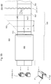
- the at least one knife unit 521 can be moved transversely to the transport direction F of the incoming printing substrate 002 ', in particular remotely actuated and / or set by motor (see as an example for the other examples in FIG Fig. 8 indicated).
- a drive means 527 which effects the position or a control assigned to it is in signal connection with a control means 528, for example.
- This control means 528 can provide information relating to the position of the required cutting line s relating to the product P to be manufactured or control data and / or signals S W prepared accordingly in this regard For example, a signal connection from a higher-level control device 802 can be or will be forwarded.
- the further processing section 003 in particular in the area of the printing substrate guide section 500, can have a one or more part further processing stage 507 for aligning the printing substrate 002 'in the longitudinal and / or in the transverse direction, eg. B. include a one-part or multi-part alignment device, in particular a single or multi-part register device 507 for correcting the position of the printing material 002 'in the transverse direction and / or in the longitudinal direction. This can be downstream of a possibly provided combination device 502; 503; 504 and / or upstream of the cross-cutting device 513 provided for the web-shaped printing material 002 'in the printing material path.
- the further processing section 003 in particular in the area of the printing substrate guide section 500, one or more single or multi-stage further processing stages 508, which are combined under the reference symbol 508 and allow conditioning of the printing substrate 002 ', in particular a processing stage 508 designed as a conditioning and / or treatment stage 508, be provided.
- This further processing stage 508 can be or include, for example, a perforating or creasing device and / or a plow folding device for wrapping a printing material side and / or an application device for applying a fluid and / or a dryer for drying the printing fluid and / or an irradiation device for supporting the curing process .
- One or more of these devices can be located downstream of a possibly provided combination device 502; 503; 504 and / or upstream of the cross-cutting device 513 provided for the web-shaped printing material 002 'in the printing material path.
- a mechanical treatment stage 509 can be provided in the printing material path, which, for example, acts as a weakening line on the printing material 002 ', e.g. B. but not completely cutting processing device 509, in particular as a perforating or creasing device 509, is formed.
- This perforating or creasing device 509 can comprise a longitudinal perforating or creasing device or a transverse perforating or creasing device or both a longitudinal perforating or creasing device and a transverse perforating or creasing device and / or is, for example, the last of several in the printing material path the cross-cutting device 513 or - in the case without a cross-cutting device 513 - the exit of the substrate guide 500 provided for further processing stages 502; 503; 504; 506; 507; 508; 509 arranged.
- the further processing section 003 in particular in the area of the printing substrate guide section 500, can be used instead of or in addition to one or more of the treatment and / or conditioning agents mentioned and / or treatment stages 508; 509 in the printing material path of an already longitudinally divided, ie partially wide printing material 002 ', a conditioning of single or multi-stage further processing stages 511 which enables the printing of substrate 002' divided by longitudinal section, in particular a processing stage 511 designed as a conditioning and / or treatment stage 511, to be provided.
- This further processing stage 511 can, for example, be or comprise a perforating or creasing device and / or a plow folding device for turning in a printing material side and / or an application device for applying a fluid and / or a registering device for longitudinal registration of an individual layer.
- the further processing section 003 in particular in the area of the printing substrate guide section 500, can be used instead of or in addition to one or more of the treatment and / or conditioning agents mentioned and / or treatment stages 508; 509; 511 in the substrate path of the substrate 002 ', which has not yet been slit, a conditioning of the substrate which has not yet been slit, i.e. H. single or multi-stage further processing stages 512, in particular a processing stage 512 designed as a conditioning and / or treatment stage 512, can be provided which still provide the full width of substrate 002 '.
- This can for example be a painting device, e.g. B. a so-called. Coating unit, and / or an application device for applying a z. B. silicone-containing liquid, for. B. a so-called. Siliconmaschine, be or include.
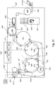
- z. B. in Fig. 6 is a schematic representation of a first example of the execution of a production line for processing and processing web-shaped printing material 002, wherein the dashed line running vertically through the further processing section 003 is intended to symbolize, for example, the height of a kink to be provided in the case of a 90 ° arrangement.
- This line then runs, for example, in the area of turning bars of an above-mentioned diversion device 503.
- the production line comprises the printing press 001 with at least one printing unit 200 which preferably works without a printing form; 400 and this is followed by a further processing section 003 with a strand guiding and / or forming section 500 which, in addition to one or more conveying and / or guiding devices 501, at least the transverse cutting device 513 and possibly one or more further of the above-mentioned further processing stages 502; 503; 504; 506; 507; 508; 509; 511; 512 includes.
- This is followed by a collection and / or Folding section 600 with one or more further processing stages 601; not shown here in detail. 602; 603; 604; 606; 607; 608; 609; 611; 612.
- the production line (see e.g. Fig. 7 ) with a printing press 001 and a gathering and / or folding section 600 of essentially the same nominal size b N (D); b N (SF) can be formed, ie b N (D) ⁇ b N (SF).
- the printing press 001 or the printing unit 200; 400 or the printing unit 211 In a double-width version, the printing press 001 or the printing unit 200; 400 or the printing unit 211,
- 411 thus has a nominal width which essentially corresponds to twice the maximum inlet width or nominal width of the collecting and / or folding section 600, that is to say b N (D) ⁇ 2 ⁇ b N (SF).
- b N (D) the maximum inlet width or nominal width of the collecting and / or folding section 600
- the working width of the at least relating to a single-width section that is to say the m-th, in this case half of the nominal width b N (D) a printing unit 211; 411 and the maximum inlet width in the collecting and / or folding section 600 by, for example, only up to half, possibly only by up to a third, or even by up to a quarter, of the maximum inlet width or nominal width b N (SF) differ from each other.
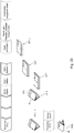
- the in z. B. the Fig. 7 schematically indicated first embodiment of the production line in z. B. single-width design of the printing press 001 and / or the at least one printing unit 200; 400 and / or the at least one printing unit 211; 411 is arranged downstream of the printing press 001 - basically regardless of the design variant as a straight-line press line or in an angled arrangement - which, in a preferred embodiment, has at least one as a cross-cutting device 513 and at least one as a cross-folding device 602 and possibly at least one as a collecting device 601 on a processing line ; 603 further processing stage 513; 601; 602; 603 includes.
- this first embodiment for the production line in the variant of the angled arrangement includes the further processing section 003, in particular the strand routing and / or forming section 500, for example a further processing stage 503 designed as a diversion device 503.
- a web 002 is printed or is printable, which for example has a web width b002 corresponding at most to the nominal width b N (D).
- a format f (B) different from the first format f (Z, T) and / or with a different orientation from a first page orientation are printed side by side.
- a single-width exit web 002 after cross-cutting, single-layer sections 002 ', k can be provided or provided for further processing in the collecting and / or folding section 600, provided they are not brought together with one or more further single-width exit webs (see below) .
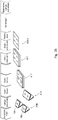
- a z. B. in Fig. 8 schematically indicated second embodiment of the production line in z. B.
- multiple-width (m> 1), in particular double-wide design of the printing press 001 and / or the at least one printing unit 200; 400 and / or the at least one printing unit 211; 411 is arranged downstream of the printing press 001 - basically regardless of the design variant as a straight-line press line or in an angled arrangement - a further processing section 003, which in a preferred embodiment is located on a processing line - e.g. B.
- the further processing section 003 in particular the Strand guiding and / or forming section 500, as the at least one combining device 503 or additionally include a further processing stage 503 designed as a diversion device 503.
- a web 002 is printed or can be printed, which has, for example, a web width b002 corresponding at most to this “multiple-width” nominal width b N (D).
- the at least one union device 502; 503; 504 having strand guide and / or formation section 500 are thus multi-layered, e.g. B.
- two-layer sections 002 ', k - depending on its design without or with a paired connection in the area of a fold back - can be provided or provided for further processing in the collecting and / or folding section 600.
- the at least one as a union device 502; 503; 504 of the second embodiment for the production line can basically be formed in one of the above-mentioned embodiments.
- a first embodiment for the union device 502; 503; 504 - in particular in connection with the variant for the production line as a straight-ahead machine - this can be used as a turning device 502 with at least one pair of turning bars 514; 517 (see e.g. Fig. 9 ), through which a strand 002, which, for. B. is formed as a partial web 002 'from a whole web 002' or by a partially wide original web 002, transversely to its direction of conveyance F present in the inlet to the turning device 502, to an escape of another such strand 002, and thus already there or in further course is to be combined with this to form a multilayer strand.
- a strand 002 which, for. B. is formed as a partial web 002 'from a whole web 002' or by a partially wide original web 002, transversely to its direction of conveyance F present in the inlet to the turning device 502, to an escape of another such strand
- the turning device 502 can be designed as a bay window and / or fall-back device or additionally comprise one, for example by a roll 516 designed as a fall-back or bay window roll 516 and one opposite another of the turning bars 514 - in one considered horizontal projection plane - has turning bar 517 inclined by 90 °.
- At least one of the turning bars 514; 517 can be moved transversely or longitudinally to the transport direction F of the incoming printing substrate 002 ', in particular remotely actuated and / or can be adjusted by motor (see as an example for the other examples in Fig. 9 indicated).
- a drive means 529 causing the position or a control assigned to it is in signal connection with a control means 531, for example.
- This control means 531 can be supplied with information relating to the product P to be produced regarding the position resulting from the required strand routing or control data and / or signals S W that have already been correspondingly prepared in this regard - for example via a signal connection from a higher-level control device 802.
- the union device 502; 503; 504 - in particular in connection with the variant for the production line in an angled arrangement - it can be used as a diversion device 503 with at least two diversion or turning rods 514; 517 be formed (see e.g. Fig. 10 ), through which two strands 002 ', which z. B.
- the diversion device 503 can at least partially be designed as a bay window and / or fallback device or additionally comprise one, for example by a roll 516 designed as a fallback or bay window roll and one opposite another of the turning bars 514-in viewed in a horizontal projection plane - has turning bar 517 inclined by 90 °.
- At least one of the diversion or turning bars 514; 517 can be moved transversely or longitudinally to the transport direction F of the incoming printing substrate 002 ', in particular remotely actuated and / or can be adjusted by motor (see as an example for the other examples in Fig. 10 indicated).
- a drive means 532 which effects the position or a control assigned to it is in signal connection with a control means 533, for example.
- This control means 533 can be supplied with information relating to the product P to be produced regarding the position resulting from the required strand routing or control data and / or signals S W which have already been prepared accordingly in this respect - for example via a signal connection from a higher-level control device 802.
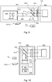
- a folding former 504 in particular in connection with the variant for the production line in an angled arrangement - this can be designed as a folding former 504 (see e.g. Fig. 11 ), over which two parts of the web that have already been split or are still undivided, in particular in the alignment of the funnel tip, in particular web halves, are laid one on top of the other as unconnected strands 002 'or connected to one another in the fold back running along a longitudinal fold line I. become. These two web parts can then as a multilayer, still in the fold z. B. strand 002 'connected in pairs, e.g. B.
- a longitudinal cutting device 506 which is associated or arranged upstream of the folding former 504, is provided in the strand path. After the cross cutting are depending on the existing funnel center cut multilayer, z. B. two-layer sections 002 ', k without or with a paired connection in the area of a fold back for further processing in the collecting and / or folding section 600 can be provided or provided.
- the folding former 504 can be moved transversely and / or longitudinally to the transport direction F of the incoming printing substrate 002 ', in particular remotely actuated and / or can be adjusted by a motor (see as an example for the other examples in Fig. 11 indicated).
- a driving means 534; 536 or a controller assigned to it is in signal connection with a control means 537, for example.
- This control means 537 can be supplied with information relating to the product P to be manufactured regarding the position resulting from the required strand routing or control data and / or signals S W which have already been prepared accordingly in this regard - for example via a signal connection from a higher-level control device 802.
- the product range can be expanded particularly advantageously by one of the following further training variants.
- the further processing section 003 which is preferably arranged downstream in an angled arrangement, comprises at least two turning bars 514 on a guide or processing section upstream of the cross-cutting device 513; 517; 519, for example at least one full-width turning bar 514, 517 and / or at least one part-wide turning bar 518 based on maximum web width b002, in a third development a folding former 504 and in a fourth development both at least one with a length for leading out a the maximum web width b002 max turning bar 514; 517 as well as a folding former 504 (see e.g. Fig. 14 ).
- the respective union device 502; 503; 504, a longitudinal cutting device 506 with at least one knife unit 521 is arranged upstream in the guide or processing section.
- the product range can be expanded particularly advantageously by one of the following further training variants.
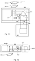
- the processing section 003 which is arranged downstream of the printing press 001, preferably in an angled arrangement, comprises a turning device 502 on a guide or processing section upstream of the cross-cutting device 513, through which a longitudinally separated part of the multiple-width web 002 'as a strand 002' over a other such part is feasible (see e.g. Fig. 15 ), as well as a folding former 504 arranged downstream of this turning device 502 in the printing material path, through which the already guided one another, e.g. B. now single-width strands 002 'without or with a funnel center cut above the Folding former 504 can be guided on one another.
- a turning device 502 on a guide or processing section upstream of the cross-cutting device 513, through which a longitudinally separated part of the multiple-width web 002 'as a strand 002' over a other such part is feasible (see e.g. Fig. 15
- the further processing section 003 which is arranged downstream of the printing press 001, preferably in an angled arrangement, on a guide or processing line upstream of the cross-cutting device 513, comprises both a rejection device 503, by means of which longitudinally separated parts of the multi-width web 002 'can be rejected as strands 002' and can be guided one above the other is (see e.g. Fig. 16 ), as well as a folding former 504 arranged downstream of this turning device 502 in the printing material path, through which the already guided one another, e.g. B. now single-width strands 002 'without or with a funnel center cut over the former 504 on each other can be performed.
- a rejection device 503 by means of which longitudinally separated parts of the multi-width web 002 'can be rejected as strands 002' and can be guided one above the other is (see e.g. Fig. 16 ), as well as a folding former 504 arranged downstream of this
- a longitudinal cutting device 506 which can be activated optionally, can be provided.
- the cross-cutting, multilayered, z. B. four-layer sections 002 ', k as a single sheet or as a double sheet with a paired connection in the area of a fold back for further processing in the collecting and / or folding section 600 can be provided or provided.
- the strand guiding and / or forming section 500 can be provided as a further processing stage 521, through which a printing material stream is guided along a guide section, forming a printing substrate switch 521 can be guided as a whole into a first adjoining guide section or into a second adjoining guide section (see, for example, in Fig. 16 ).
- This handling stage 521 is preferably also designed to selectively divide the supplied printing material flow, so that part of the printing material flow can be guided and / or guided in the first subsequent guide section and another part in the second subsequent guide section.
- the further processing stage 521 in the guide path of the relevant multilayer printing material stream eg. B. strand bundle, at least one, in particular at least two, conveyor and / or guide device 522 forming handling means 522, which are designed for example as rollers 522 or rods 522.
- two or more printing machines 001 or printing units 200; 400 may be provided, through which two or more webs 002 are printed simultaneously and these or partial webs 002 ′ obtained therefrom can be guided into a downstream processing section 003.
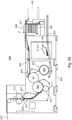
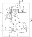
- these strands 002 'formed by the webs 002' itself and / or by partial webs 002 'obtained therefrom are to be combined and - in particular after cross-cutting into correspondingly multilayered sections 002'k - further processed together in the downstream collecting and / or folding section 600 (see e.g. 17 and 18 ).
- the - at least during the operation in the network - comprises the at least two printing presses 001 and / or printing units 200; 400 extensive production line in the printing material path of at least one of the at least two webs 002 ', a handling stage 532 forming a combination device 523, through which at the same time different printing machines 001 and / or printing units 200; 400 originating tracks 002 'can be combined into a common track.
- the combination device 523 can, for example, optionally be taken into account in the printing material management, or can be taken into account or not taken into account, in the first case then for example a mixed production and in the second case a separate production takes place and / or can take place.
- a rear one of the printing presses 001 or printing units 200; 400 a combination device 523 with handling means 524 for transferring or transferring a front of the printing presses 001 or printing units 200; 400 are provided, which are formed, for example, by conveying and / or guiding devices 524 designed as rollers 524 or bars 524.
- All of the above-mentioned embodiments, embodiments, further developments and variants for the configuration of the strand guiding and / or forming section 500 can in principle be of any design, for example, however, at least one as a transverse folding device 602 and possibly at least one as a collecting device 601; 603 trained further processing stage 601; 603 comprehensive collection and / or folding section 600.
- a collecting and / or folding section 600 is arranged downstream, as is described in one of the embodiments, embodiments, further developments and variants set out below.
- a collecting and / or folding section 600 is arranged downstream of the printing material guide section 500, this can only be conveyed through the printing material guide section 500 on the input side and, if appropriate, in particular for the case of a printing material 002 'which is present in web form on the input side, by cross cutting a web form
- This one or multilayer sections 002 ', k can additionally by one or more conditioning stages 508; 509; 511; 512 mechanically and / or chemically and / or physically conditioned and / or pre-assembled in terms of dimensions in the manner set out above.
- the configuration examples and variants set out below for the design of the collecting and / or folding section 600 can in principle be used with all combinations for the expansion stage of the upstream printing material guide line 500, ie. H. with at least one unification device 502; 503; 504; 523 forming handling level 502; 503; 504, in particular a turning device 502 and / or a diversion device 503 and / or a longitudinal folding device 504 and / or a combination device 523 for webs 002 'of different origins, and / or with at least one register device 507 and / or with at least one mechanical processing stage 506; 508; 509, in particular a longitudinal cutting device 506 and / or a cross cutting device 513 and / or a perforating or creasing device 509, and / or with at least one conditioning device 508; 511; 512, in particular at least one conditioning device 511 relating to a part-width strand and / or at least one conditioning device 512 relating
- the further processing section 003, in particular in its collecting and / or folding section 600 preferably comprises at least one as handling stage 601; 611, in particular as a collecting device 601; 611 further processing stage 601; 611, by means of which one or more intermediate products 002 ', k; 616; 617 to several, preferably two or even more than two, can be collected on one another, and / or at least one listed as a folding device 602, in particular as a transverse folding device 602
- the at least one first collecting device 601 can have at least one further handling stage 603; trained further processing stage 603, z. B. a pre-collection device 603 designed further processing stage 603.
- the intermediate products 002 ', k; 617 are separated by single or multi-layer sections 002 ', k or by already several in bundles 617; 617 'combined and, if necessary, stapled single or multilayer sections 002', k are formed.
- the intermediate products 002 ', k; 617 - depending on the stage of development of the further processing section 003 and / or after activation, further processing stages 601; 602; 603; 606; 607 - for example as single-layer or multi-layer sections 002 ', k itself provided by the printing material guide section 500 on the output side, H.
- a bundle 617; 617 ' which can be formed by pre-collecting such single- or multi-layer sections 002', k upstream of the collecting device 601 in, for example, an upstream additional collecting device 603, e.g. B. a pre-collection device 603, into several bundles 617; 617 'are formed by sections 002', k.
- the first-mentioned collecting device 60 possibly also by means of a pre-collecting device 603 provided in an advantageous embodiment, enables a plurality of intermediate products 002 ', k; 617; 617 'or a plurality of not directly, but by means of one or more such copies spaced apart from one another in the printing material stream, or preferably alternatively both directly successive intermediate products 002 ', k; 617; 617 'and also intermediate products 002', k; spaced apart from one another by one or more copies in the printing material stream; 617; 617 'to be collected into several.
- a collection sequence which is based on the collection and relates to a same product copy ie. H. the collection pattern relating to the successively arriving sections 002 ', k, 002', k + 1, 002 ', k + 2 etc. is constant over the sections 002', k to be collected for the same product specimen or parts thereof.
- it can instead or additionally to this in another operating situation for the production of a product P with e.g. B. several product parts of different layers and / or number of pages can be provided that the collecting sequence on which the collecting varies over the sections 002 ', k to be collected for a same product copy or its parts.
- control means 682; 683; 684 e.g. as a control circuit or preferably in digitized form as values or function in a data storage and / or processing device provided there
- control means 682; 683; 684 e.g. as a control circuit or preferably in digitized form as values or function in a data storage and / or processing device provided there
- - for example synchronized to the substrate advance - when controlling the holding means 626; 651 are taken into account.
- the movement of the holding means 626; 651 or the switch 647 (652) controlling drive preferably mechanically independent of a collecting device 601; 603 e.g. B. rotary drive.
- the drive can be a single or multi-part control disc be formed, which can be rotated by a drive motor that is mechanically independent of other components, and with the holding means 626; 651 works together to control their movement.
- the information representing the collective sequence can be stored, but can be changed in the course of parameterization.
- the cross-cutting device 602 leaves a cross-folded intermediate product 616 which, depending on the stage of expansion and / or activation, by a folded single or multi-layered section 002 ', k, by a folded, collected or pre-collected section bundle 617; 619 or by a folded bundle joint 619 with at least one pre-collected section bundle 517 and at least one further section 002 ', k and / or section bundle 517.
- At least one device 606; connecting a plurality of layers along a transverse line h; 607, in particular as a cross-glue or preferably as a cross-stitching device 606; 607 trained further processing stage 606; 607 may be provided.
- the at least one device 606; connecting a plurality of layers; 607 is preferably arranged directly or indirectly in the printing material path of the transverse folding device 602.
- the at least one device 606 connecting a plurality of layers is; 607, for example, to this collecting device 601 or directly or indirectly after it in the printing material path.
- both the pre-collection device 603 and the collection device 601 can each have a device 606; 607 can be assigned or subordinated.
- the further processing section 003, in particular in the region of the processing section 600 can comprise at least one processing stage 604, in particular further processing stage 604 designed as a longitudinal cutting device 604, through which individual folded sections 002 ', k, z. B.
- Such a longitudinal cutting device 604 can preferably be provided downstream of the at least one transverse folding device 602 and / or downstream of the at least one collecting device 601 in the printing material path.
- the further processing section 003, in particular in the region of the processing section 600 can have at least one as a folding device 608; 609, in particular as a longitudinal folding device 608; 609 trained processing stage 608; 609 or further processing stage 608; 609 comprise, through which - depending on the equipment and / or activation of the processing section 600 - individual single or multi-layer sections 002 ', k, z. B.
- Such a longitudinal folding device 608; 609 may preferably be provided downstream of the at least one transverse folding device 602 and / or downstream of the at least one collecting device 601 in the printing material path.
- said or an additional longitudinal folding device 608; 609 can be provided in the printing material path upstream of the at least one transverse folding device 602 and / or the at least one collecting device 601 in the printing material path.
- both one of the at least one transverse folding device 602 and / or the at least one collecting device 601; 603; 604 upstream as well as one of the at least one transverse folding device 602 and / or the at least one collecting device 601; 603; 604 can be provided in the substrate path.
- the longitudinally folded intermediate product 002 ', k; 617; 618 or finished product P can be discharged via, for example, a conveyor section 613 in a conveying direction F 'inclined by 90 ° to the previous conveying direction F.
- the longitudinally folded intermediate product 002 ', k; 617; 618 or finished product P pass through a pressing device 614, through which the longitudinal fold formed gains sharpness and / or the product height in the region of the fold is reduced.
- a further longitudinal folding device 612 which is arranged downstream of a longitudinal folding device 609 in the printing material or product path, is preferably provided in an embodiment of the further processing section 003 and / or the handling and / or processing section 600, in which the printing material path upstream of the first of the two in the same longitudinal folding devices 609 without, at least without an active transverse folding device.
- a processing section provided for such further processing of sections 002 ', k here comprises two longitudinal folding devices 609; 612, but no or at least no active transverse folding device.
- the intermediate product 002 ', k; 617; 618 or finished product P is re-routed through 90 ° via, for example, a further conveyor line 613 and, if necessary, via further conveyor lines 613 for storage and / or picking in or on z.
- a storage device 700 are supplied or be.
- a treatment device 614 designed as a pressing device 614 can be provided on downstream of folders 602; 608; 609; 614.
- the last further processing stage provided in the single or in the relevant one of several conveying paths or in the respective processing section is provided, for example, with a conveyor section, for example a delivery belt or a gripper, on or through which the products P are fed to the storage device 700 and can be saved and / or commissioned.
- a conveyor section for example a delivery belt or a gripper
- the further processing section 003, in particular the collecting and folding section 600 comprises a first group of exemplary embodiments, further developments and variants (see, for example, 19 to 22 ) at least one transverse folding device 602 and / or at least one collecting device 601; 603; 611, e.g. B. at least one designated here as the main collector 601. Collecting device 601. This is or are arranged - in particular in the case of a web-processing further processing section 003 - in the printing material path downstream of a cross-cutting device 513 which may be provided.
- the first along the substrate flow, through a collecting device 601; 603; 611 or a cross-folding device 602 further processing stage 601; 602; 603; 611 of the gathering and folding section 600 is arranged on the input side a conveyor line 638 with a conveyor system 627, for example a belt system 627, through which the sections 002, k arriving in the printing material flow der concerned, as collection device 601; 603 or further processing stage 601; 602; 603; 611 can be fed.
- the single or multi-layered sections 002 ', k to be fed in on the input side of the collecting and folding section 600 can - for. B.
- a sheet-processing further processing section 003 - by the input side of the further processing section 003 as printed sheets 00'2, k individual sheets 002 ', k or "pre-collected" sheet bundles 617 (see, for example, indicated in the entrance area of the Fig. 19 ), or - e.g. B.
- a web-processing further processing section 003 - be formed by single or multi-layer web sections 002 ', k cut from a single or multi-layer strand 002' by means of a cross-cutting device 513 or by pre-collected bundles 617 of such web sections 002 ', k (see e.g. For example, indicated in the entrance area of the Fig. 19 as well as in the Figures 20 to 22 .
- the transverse folding device 602 and / or the only or first collecting device 601; 603; 611 is designed in the printing material path with a nominal width b N (W) given by the maximum processing width in order to accommodate and process single or multi-layer sections 002 ', k with a width up to this nominal width b N (W).
- this width of the sections 002 ', k can in principle correspond in width to the printed image width of one or more printed pages side by side.
- a first product P to be produced for example a newspaper or tabloid product P (Z); P (T), the sections 002 ', k can be, for example, one-page wide with respect to the printed image applied to the printing material 002', ie in width comprising a printed page image of only one printed page, in particular comprising a printed page image of a lying print page, that is to say with the page height running in the transverse direction , be formed, whereas with respect to a second product to be manufactured P, e.g. B.
- a book product P (B) the width of the in relevant processing stage 601; 602; 603; 611 to be processed and / or processable section 002 ', k which can be formed, for example, two-page width, ie in width a printed page image of two printed pages, in particular the printed page images of two standing, ie with the page height in the conveying direction F, comprising printed pages.
- the at least one, e.g. B. the cross cutting device 513 downstream downstream, cross folding device 602 is preferred as a rotating folding cylinder 621; 623 comprehensive transverse folding device 602 formed.
- a rotating folding cylinder 621; 623 comprehensive transverse folding device 602 formed can basically be designed as a wheel folding unit with a rotating collecting and folding knife cylinder and a cooperating folding roller gap
- it is preferably designed as a flap folding unit and comprises a cylinder 621 designed as a folding cylinder 621, e.g. B. folding cylinder 621, on its circumference viewed in the circumferential direction at least one folding jaw 622 or axially extending row of folding jaws 622 is provided and / or which has an outer circumference which is essentially, ie plus max.
- a lower limit is given, for example, by a length preferably in the range from 360 to 480 mm, in particular in the range from 400 to 440 mm, possibly by a length of 420 ⁇ 10 mm.
- the folding cylinder 621 has two folding flaps 622 or two axially extending rows of on its circumference in the circumferential direction Folding jaws 622.
- the transverse folding device 602 comprises a further cylinder 623, e.g. B. folding cylinder 623, a with the folding jaw cylinder 621 cooperating transport and folding knife cylinder 623, considered on the circumference in the circumferential direction at least one axially extending folding tool 624, z. B. folding knife 624, and / or at least one receiving means 626, z. B.
- the transport and folding knife cylinder 623 preferably has two such receiving means 626 or group of grippers 626 and two folding tools 624, for example each arranged between the receiving means 626, at their circumference in the circumferential direction one behind the other at a distance of approximately 180 °.
- the collection cylinder 649 has a "simple" scope and / or possibly only one or only one group of receiving means 626.
- this can be formed by a transport and folding knife cylinder 623 which can be operated as a collecting cylinder 623.
- this includes mechanically and / or electronically controllable adjusting means which are designed to cause an already recorded section 002.k to pass through the nip point with the downstream one at least for the first time Folding jaw cylinder 621 is not yet delivered to this, but in the area of an input-side feed to the transport and folding knife cylinder 623 by the receiving means 626 one or more further incoming single or multi-layered sections 002.k or pre-collected section bundles 617 are only picked up and only at the next or after z. B.
- the section 002 ', k or the bundle 617 or the bundle joint 619 becomes the folded intermediate product 616, e.g. B. a product section 616 folded.
- the collecting sequence on the folding cylinder 623 which can be operated as a collecting cylinder 18, can be varied in the manner explained above from production to production or - for example for the production of sections 617 of different page numbers - preferably also to form product sections of the same product copy.
- the folding jaw and collecting cylinders 621; 623 comprising transverse folding device 602 formed a gathering and folding unit 602 comprising both further processing stages.
- the product section 616 obtained by the cross folding can, in a first, simplest embodiment (see e.g. Fig. 19 and Fig. 20 ) or production, in which no further processing or processing steps are provided or required for the product P to be manufactured in the processing section in question, form the product P itself.
- the intermediate product 616 or product P delivered by the cross-folding device 602 or by the folding jaw cylinder 621 is then fed, for example, on an conveying path 631 comprised by the processing path provided for the product P, to an output of the further processing section 003 and, for example, to storage and / or order picking.
- the conveyor section 631 can be a for example as a conveyor system and / or a so-called paddle wheel 628 and / or a z. B. designed as a display 629 conveyor 629.
- this one collecting device 601; 603 and / or a transverse folding device 602 comprising the further processing section 003, in particular the folding and / or collecting section 600, a processing section with a further processing stage 608 designed as a longitudinal folding device 608 and arranged downstream of the transverse folding device 602 in the printing material path.
- the processing lines - in particular in an upstream part of the processing lines - can have at least one common line section.
- the longitudinal folding device 608 can in a first embodiment, such as. B. in the figures Fig. 19 and Fig. 20
- a second conveyor line 632 which is different from the first conveyor line 631 and is to be assigned to the first processing line, can then be provided, which then forms part of a second processing line.
- the cross-folding device 602 in the printing material path can be followed by a branch 633 in the conveying path, for example in the form of a product switch 633, through which the transversely folded intermediate products 616 can optionally be fed into the first conveying section 631 and to the product delivery 629 or via the second conveying section 632 of the downstream longitudinal folding device 608.
- the longitudinal folding device 608 such as. B. in the figures Fig. 21 and Fig. 22 Recognizable by way of example, it can be provided in the first first conveyor line 631 leading to the first output, ie in the printing material path of the first processing line.
- This longitudinal folding device 608 can be inactive in production via the first processing section and of the cross-folded intermediate products 616 be run through without any editing.
- the cross-folded intermediate products 616 can be folded lengthwise by the longitudinal folding device 608, with reference to the conveying direction F present at the infeed, with the branching device 608, for example, branching, e.g. B. the product switch is formed to divide the processing line.
- the intermediate product 634 which is first folded transversely and then lengthwise can itself be the product P; Train 634.
- the intermediate product 634 or product P delivered on the output side by the longitudinal folding device 608 is then forwarded, for example on the second conveyor line 632, to an output of the further processing section 003 and, for example, to storage and / or order picking.
- the conveyor section 632 can be a so-called paddle wheel 636 and / or a z.
- B. include delivery device 637 designed as delivery 637 (see, for example, in Fig. 19 , Fig. 21 and Fig. 22 ).
- lead the second conveyor section 322 for example directly after leaving the longitudinal folding device 608, into a storage device 700, for example a stack delivery 700.
- the longitudinal folding device 608 is preferably designed as a longitudinal folding device 608, also referred to as a so-called sword folding device 608, with a folding tool 641, e.g. B.
- a folding blade 641, also known as a folding blade can be moved cyclically towards and away from a folding table 642, in particular up and down, so that it plunges into a folding gap of the folding table 642 during the downward movement and into it
- Point in time intermediate product 616 present on folding table 642; 617; 618; 619 presses through the folding nip between a pair of folding rollers 643 and in doing so acts upon the longitudinal fold running along the longitudinal folding line I, before this as an intermediate product 634 (e.g., previously folded crosswise, at least once) (e.g. exemplarily in Fig. 21 indicated) the longitudinal folding device 608; 609 leaves.
- an intermediate product 634 e.g., previously folded crosswise, at least once
- the collecting device 601 can connect a plurality of layers which have been collected to one another, with or without a longitudinal folding device 608 provided and / or activated in the processing line in the manner mentioned Device 606; 607, in particular a cross-stitching device 606; 607, to be subordinate to, middle or immediate.
- This facility 606; 607 can in principle be spaced upstream from the upstream collecting device 601; 603 may be provided, but is in a preferred embodiment as a so-called layer stapler 606; 607 with a stapling cylinder 644 acting together with the collecting cylinder 623 as an abutment.
- Layers to be connected can be formed by a plurality of single- or multi-layer sections 002 ', k or possibly by bundles 617 of sections 002', k already pre-collected and then correspondingly connected, in particular stitched, intermediate products 617; Train 619.
- staples 653 for example indicated on the intermediate product 616 in Fig. 20
- Layers to be connected can be formed by a plurality of single- or multi-layer sections 002 ', k or possibly by bundles 617 of sections 002', k already pre-collected and then correspondingly connected, in particular stitched, intermediate products 617; Train 619.
- the terms “stapling cylinder” not only include strictly cylindrical rotating bodies here, but also, in common usage here, rotating bodies with the relevant stapling tools, which essentially rotate on a circular line when the body rotates.
- the at least one device 606; 607, in particular cross-stitching device 606; 607, can be activated optionally and preferably in its work or stapling sequence from production to production or - for example for the production of stapled sections 617 different page numbers - preferably also for the production of connected or stapled and unconnected or unstitched intermediate products 617; 619 of the same product copy can be varied.
- a cross-stitching device 606; 607 this is set up to the cross-stitching device 606; 607 continuous sections a, i; 002 ', k or bundle 617 in one or preferably in several, e.g. B. two tracks HS1; HS2, especially by introducing z. B. as staple threads or preferably staples 653 designed stapling means 653 to staple.
- multiple tracks HS1; HS2 takes place, for example, at least in two tracks HS1 which are closest to the respective edge area; HS2, ie two outer tracks a stapling, whereby this can be left or one or more additional tracks can be provided in between.
- stapling means 653 which, viewed from the same side edge, the same single, outer or inner row of the sections a, i; 002 ', k or bundle 617 of staples 653 introduced or to be incorporated.
- two such tracks HS1; HS2 in the case of three staplings three tracks HS1; Be HS2.
- the traces HS1; HS2 can - based on the relative lateral position on the sections to be stapled a, i; 002 ', k or section bundles 617 - each can be introduced or inserted in the same alignment, ie in the same lateral position.
- a, i; 002 ', k or bundle 617 staplings introduced or to be introduced or stapling means 653 of the same staple track HS1; HS2 vary in their lateral, ie viewed in the transverse direction.
- the folding and / or collecting section 600 can - with or without one longitudinal folding device 608 provided and / or activated in the processing section in the aforementioned manner and with or without a device 606 provided and / or activated in the processing section in the aforementioned manner; 607 for connecting layers - in a - particularly for newspaper production - advantageous embodiment of the folding and / or collecting section 600 of the at least one transverse folding device 602 in the printing material path of the processing line, a collecting device 611 designed for collecting several transversely folded intermediate products 616, e.g. B. a section collection device 611, downstream.
- Folded intermediate products 616 can be processed further by the collecting device 611 to form an intermediate product 616 which comprises a bundle 619, e.g. B. section bundle 619, such intermediates 616, z. B. sections 616, one on top of the other,
- the collection sequence of the section collection device 611 can be varied from production to production, for example for the production of successive products with section bundles 619 of different section numbers.
- the section collection device 611 can, for example, a z. B. here as collecting cylinder 646, in particular section collecting cylinder 646, designated rotating body 646, holding means 648 for holding sections 616 to be collected on body 646 and, in an advantageous embodiment, an adjustable switch 647, through which incoming intermediate products 616 or section bundles 619 already collected one or more times can optionally be fed again to a collection cycle or be delivered to a downstream conveyor section, which can be provided by a section of the route continuing the conveyor section provided on the input side.
- the intermediate product 619 formed by the section bundle 619 can be supplied to a product delivery 628 or directly to a storage device 700 via this route section or a conveyor route continuing this, possibly via a paddle wheel 628.
- a longitudinal folding device 608 is arranged downstream of the processing section, the section bundle 619 can be longitudinally folded there and leave the longitudinal folding device 608 as a longitudinally folded - but previously also transversely folded - intermediate product 634.
- this can represent the product P to be produced. As explained below, this can in particular be a newspaper or tabloid product P (Z); P (T).
- the section collecting cylinder 646 preferably has a circumference corresponding to the circumference of the main collecting cylinder.
- the holding means 648 can in principle be by means of receiving means comparable to the grippers mentioned, it being possible to dispense with the switch.
- the holding means 648 are preferably designed as a belt system 648, by means of which the intermediate products 616 forced into a first or renewed collecting cycle by means of the switch 647 are held on the outer contour of the rotating body 646.
- the switch 647 can be designed as a pivotable tongue 647 or tongue group 647.
- the folding and / or collecting section 600 with or without a longitudinal folding device 608 provided and / or activated in the processing section in the manner mentioned, with or without one in the processing section in the manner mentioned provided and / or activated device 606; 607 for connecting layers and with or without a section collecting device 611 provided and / or activated in the processing section in the manner mentioned - the collecting device 601, also referred to as the main collecting device 601, can be located in the processing section, directly or at a distance from it, another, in the processing section z. B. in this case, first collecting device 603, z. B. a collection device 603, referred to here as pre-collection device 603, may be arranged upstream.
- the pre-collecting device 603 comprises a cylinder 649 designed as a collecting cylinder 649, in particular pre-collecting cylinder 649, and holding means 651 provided in or on the cylinder 649.
- the latter can be designed as a gripper 651 or group of grippers 651, as described above for the Main collecting device 601 are described, or as a belt system 651, as described above for the section collecting device 611.
- a guide wedge 652 which is provided, for example, a switch 657 which can be set in accordance with the aforementioned switch 647 is to be provided.
- the pre-collecting cylinder 649 preferably has a circumference corresponding to the circumference of the main collecting cylinder and / or, in the embodiment with holding means 651 arranged on the cylinder 649, has two of these holding means 651 or groups of holding means 651 one after the other in the circumferential direction. It is preferably or is operated and / or can be operated in the same direction of rotation as the main collecting cylinder 623 during production operation.
- the pre-collection cylinder 649 has a "simple" scope and / or possibly only one or a group of holding means 651.
- intermediate products 002 ', k entering the pre-collection device 603 or bundles of such 619 intermediate products 002', k which have already been collected one or more times can optionally be fed again to a collection cycle or - for example by releasing the grippers 651 or by setting the switch accordingly 652 can be delivered to a downstream conveyor line 654.
- the conveyor section 654 arranged downstream of the pre-collection cylinder 649 can be provided by a section of the conveyor system 639 arranged upstream of the pre-collection cylinder 649 or in whole or in part by its own, for example as a belt system Conveyor system be formed.
- the intermediate products 002 ', k which are present as individual single- or multi-layer sections 002', k or with pre-collection as section bundle 617, are or are 617 can be fed or fed to the main collecting cylinder 623.
- the above-mentioned device 607 downstream of the main collection device for connecting layers, in particular stitching device 607, can nevertheless be provided, but can also be omitted in an advantageous embodiment.
- a device 607 for connecting layers in particular a stapling device 606, can be arranged upstream of the main collection device 601 and downstream of the pre-collection device 603.
- the above for the first-mentioned device 606 is to be applied to the design and / or arrangement of this device 606, with the proviso that, in a preferred configuration, as a layer stapler 606, it comprises a stapling cylinder 644 which interacts with the pre-collecting cylinder 649.
- pre-collected bundles 617 of single or multi-layer sections 002 ', k can be stapled and these stapled section bundles 617 can subsequently be combined in the main collecting device 601, in particular on the main collecting cylinder 623, to form a bundle joint 619 comprising a plurality of stapled section bundles 617, before e.g. B. this is folded by the transverse folding device 602 to a cross-folded, possibly forming the product P to be manufactured product section 616.
- the collecting and folding section 600 is preferably for processing variable section lengths, in particular for processing Section lengths I002, k are formed within a range of section lengths I002, k specified above.
- the z. B. the single or first collecting device 601 601 provided in the printing material path; 603; 611 upstream conveyor line 638 is formed as an acceleration line 638, on which or through their belt system 627 incoming single or multi-layer sections 002 ', k can be accelerated in their conveying speed, if necessary, by means of a drive (not shown here) compared to the previously existing conveying speed.
- the cross-cutting device 513 is or is designed by a drive means 537, in particular drive motor 537, which is mechanically independent of drives of the downstream and / or upstream further processing stages, the rotational movement profile of which can be predetermined, for example, by a control means 538 upstream of the signal technology.
- the motion profile can be taken into account when controlling the cross-cutting device, for example, synchronized with the substrate feed.
- the information about the desired movement profile can be stored in the control means 538, but can be changed in the context of a parameterization.
- the processing section 003, in particular the folding and / or gathering section 600 of the second embodiment, can also be implemented in different, particularly advantageous configuration stages, but likewise likewise comprises at least one transverse folding device 602 and / or at least one gathering device 601; 603; 611, e.g. B. at least one designated here as the main collector 601. Collecting device 601. This is or are - in particular in the case of a web-processing further processing section 003 - arranged in the printing material path downstream of a cross-cutting device 513 which may be provided.
- the folding and / or collecting section 600 is a cross-cutting device as mentioned above Upstream 513, through which a single or multi-layer strand can be or is cut transversely into the sections 002, k.
- the cross-cutting device 513 is designed and / or driven in the above manner.
- At least one folding device 602, in particular designed as a transverse folding device 602 is provided, by means of which single or multi-layer sections 002 ', k or as previously collected and possibly pre-collected bundle 617; 619 present intermediate products 002 ', k are folded transversely to the transport direction F present on the input side of this transverse folding device 602 to form intermediate products 618 folded crosswise along a transverse fold line q can.
- the transverse folding device 602 is designed as a folding device comprising a folding jaw cylinder 621, which interacts in the manner set out above with a folding cylinder 623 designed as a transport and folding knife cylinder 623.
- the folding cylinder 623 is designed as a folding cylinder 523 which can be operated as a collecting cylinder 632
- the transverse folding device 602 comprising the folding jaw and collecting cylinders 632 forms or forms a collecting and folding unit 602 comprising both further processing stages. These can then be used to collect single-layer or multi-layer sections 002 ′, k or pre-collected section bundles 617 into several and then to fold them crosswise.
- the folding jaw cylinder 621 and of the transport and folding knife cylinder 623 what has been set out above for the first group of exemplary embodiments from the first embodiment is to be applied accordingly.
- the upstream cross-cutting device 513 can be arranged in the printing material path and / or can be designed and / or operated with a width such that, for example, a print page that only represents a later product page, for example a specific one Formats f, e.g. B. tabloid or newspaper format f (T) f (Z), preferably in a horizontal arrangement, side-by-side material web 002 'transversely in the one-sided widths or in the transverse direction the printed image of a printed page-carrying web sections 002', k can be or will be cut.
- a specific one Formats f e.g. B. tabloid or newspaper format f (T) f (Z)
- the upstream cross-cutting device 513 can be designed and / or operated in the printing material path in such a way and / or with a width that through this a printing page representing at least two later product pages, for example of a certain format f, e.g. B. book formats f (B), preferably in a lying arrangement, side by side supporting material web 02 transversely into the at least two, in particular two-sided width or the printed images of at least two web sections 002 ', k, in particular carrying two printed pages, can or will be cut.
- a certain format f e.g. B. book formats f (B)
- the upstream printing press is designed, for example, to have a single width, so that the web 002 'to be cut transversely without a prior longitudinal cut and e.g. B. without prior longitudinal folding in z. B. one- or two-sided sections 002 ', k can be cut or cut transversely.
- the collecting and / or folding section 600 is designed for processing variable section lengths I002 ', k and for this purpose comprises the conveying section 638 already set out above.
- This conveying section 638 is, for example, different in its conveying speed and / or at least in the area of the acceleration section can be driven independently of the conveying speed of an upstream preceding conveying section.
- the feed to the transport and folding knife cylinder 623 can take place predominantly horizontally, in particular on the acceleration path, i. H. with a horizontal movement component larger than a vertical component, but advantageously on a movement path inclined at most by 20 ° with respect to the horizontal, preferably essentially, ie. H. for example with a maximum deviation of ⁇ 5 °, horizontally.
- the supply to the collecting and folding device 602 or to the transport and folding knife cylinder 623 or to the conveyor system 639 which is directly upstream of the transport and folding knife cylinder 623 takes place e.g. B. clocked to the machine speed of the at least one upstream in the printing material printing unit 211; 411 and / or clocked to drive the folding cylinder 621; 623.
- Intermediate products 616 can take place directly or, preferably, indirectly via a paddle wheel 628 onto the product delivery 629, one upstream of the delivery 629 upstream, for example a conveyor section formed by a belt system, or directly onto or into a storage device 700.
- the transverse folding device 602 can be arranged downstream of a longitudinal cutting device 604 in a first development of this second embodiment, by means of which the transversely folded and possibly previously collected and / or pre-collected intermediate products 616 can finally be arranged in e.g. B. the desired products P, z. B. tabloid products P (T) or in particular book products P (B) forming product sections can be cut. These point across the transport direction F viewed z. B. only the printed image of a printed page, in particular a lying page.
- the further processing section 003 in the printing material path in front of the cross-cutting device 513 may comprise a conditioning stage 509 designed as a perforating and / or creasing device 513, by means of which the at least one perforating or creasing tool, in particular the sheet-like printing material 002 can be perforated or grooved in a line running between two adjacent printed pages.
- This facility can optionally be run inactive.
- a fourth one can be used Further development of this second embodiment or second group of examples upstream of the collecting device 601 referred to here as the main collecting device 601 and z. B. downstream of the optional cross cutting device 513, a further collecting device 603, z. B. pre-collection device 603 may be provided.
- this can also be designed as a rotating collecting cylinder, but is preferably designed here as a collecting device 603 comprising collecting pockets, in which a number of consecutive in the material flow or multilayered sections 002 ', k can be pre-collected into section bundles 617.
- the pre-collection device 603 can optionally be run through inactive.
- the further processing section 003, in particular the collecting and / or folding section 600 in a fifth further development - with or without the arrangement of a perforating and / or creasing device and with or without the presence of a longitudinal cutting device 604 and with or without the presence of a pre-collecting device 603 , e.g. B. on the substrate upstream of the cross folder 602 and z. B. downstream of a possibly provided cross-cutting device 513, at least one device 606 connecting a plurality of layers which have been collected together; 607, in particular one preferably as a cross-stitching device 606; 607 trained stapler 606; 607. This can optionally be run inactive.
- multi-layer sections 002 ', k or upstream section bundles 617 with at least one, preferably at least two staples 653 spaced apart from one another transversely to the transport direction F are to be stapled transversely.
- the cross-stitching device 606 instead or in addition to cross-stitching the sections 002 ', k or section bundle 617, which are possibly two-sided in width in this case, to the width of a printing page in each case with at least one, preferably with at least two staples spaced transversely to the transport direction T.
- a cross-stitching device 607 in the embodiment of the ply stapler 607 described above can be used in the cross-folding device designed as a collecting and folding device 602 602 can be integrated, for example, by the stapling cylinder 644 with z. B.
- the further processing section 003, in particular the collecting and / or folding section 600 can comprise a second processing line, on which the products P (B) that can be produced on the first processing line can be selected; P (T) different second products P (Z), e.g. B. from a printing material web 002 'in a standing arrangement, that is to say in the transport direction extending the page height of the printed pages forming the product pages, printed pages on the web 002.
- a first part of the further processing stages relating to the second processing line can be processed by further processing stages located in the first processing line, e.g. B. a possibly provided cross-cutting device 513 and / or a possibly provided perforating or creasing device 509 and / or a possibly provided collecting device 603, in particular pre-collecting device 603.
- further processing stages located in the first processing line e.g. B. a possibly provided cross-cutting device 513 and / or a possibly provided perforating or creasing device 509 and / or a possibly provided collecting device 603, in particular pre-collecting device 603.
- this second processing line for. B.
- At least one folding device 609 downstream of a possibly provided cross-cutting device 513 and downstream of a possibly present collecting device 29 and preferably upstream of the cross-folding device 602 possibly provided in the first processing section, at least one folding device 609, in particular a first longitudinal folding device 609 intended in the course of the second processing section, is provided by which an intermediate product 656, which can be produced, in particular only longitudinally but not transversely, can be produced and can be delivered on the output side.
- this first longitudinal folding device 609 in the second processing section is preferably a further, e.g. B. second longitudinal folding device 612 is provided, the two longitudinal folding devices 609; 612 are oriented perpendicular to one another with respect to the course of the fold to be produced, for example.
- the first and / or the second longitudinal folding device 609; 612 can in principle be designed in any configuration, but is preferably also in accordance with the longitudinal folding device 608 arranged downstream of the transverse folding device 602 and / or the main collecting device 601 as a sword folding device 609; 612 executed.
- the intermediate products 656, once folded lengthwise - possibly indirectly via a so-called paddle wheel - can be conveyed to a second longitudinal folding device 33 via a conveying path 613 with a transport direction F 'perpendicular to the previous transport direction F'.
- the first Longitudinal folding device 609 in the case of a broadsheet product, in particular a newspaper product P (Z), the so-called reading or spine folding R, produced in broadsheet production, that is to say printed production in a standing arrangement, is formed by the second longitudinal folding device 612, the so-called transport fold M.
- the second processing section can optionally also include the perforating or creasing device 509 and / or also the collecting device 603 and advantageously a second longitudinal folding device 612.
- both the first and the optionally provided second longitudinal folding device 609; 612 lie in the printing material or conveying path exclusively assigned to the second processing section.
- the first longitudinal folding device 513 is arranged in the bath material or conveying path also assigned to the first processing section.
- this first longitudinal folding device 609 for producing the first product P (T); P (B) has been or will be inactive on the first processing line.
- a pressing device 614 can be provided in a further processing stage, in particular a printing material path downstream of a folding device, in particular between the two longitudinal folding devices 609; 612 and / or downstream of the second longitudinal folding device 612.
- the collecting and / or folding section 600 can, for example, according to the in Fig. 19 and Fig. 20 for the configuration shown for the first embodiment, in particular on the output side of the cross-folding device 602, be designed with a product switch 633 to cross-fold the intermediate products 616 in the first processing section of a downstream longitudinal folding device 608 or, if applicable, as products 616 Feed a belt system (not shown) to a product delivery or, if necessary, as a double-sided intermediate product 657 still to be cut lengthwise to a conveyor line leading to the slitting device 604, which may be provided.
- the above-mentioned section length I002 ', k to be processed at most in the further processing section 003, in particular in the gathering and / or folding section 600, corresponds for example to the maximum for the printing by the upstream printing press 001 or the printing assembly 200; 400 provided variable printing section lengths L D.
- L D variable printing section lengths
- 400 is the printing section lengths L D not through the printing unit 200; 400 limited, but for the production z.
- the maximum section length I002 ', k to be processed and the associated fixed or preferably maximum for the pressure by the printing unit 200; 400 or the printing press 001 provided printing section lengths L D are in the range above for the printing section lengths L D in the first embodiment.
- variable printing section lengths L D this is given, for example, by a length of 420 to 480 mm, in particular by a length of 450 ⁇ 10 mm.
- a multi-width printing machine or printing unit 200; 400 can for the in Fig. 25 indicated case of a multi-width printing machine 001 and / or a multi-width printing unit 200; 400 and with z. B. a print sample from here, for example, more than two, e.g. B.
- the longitudinal cutting device 506 and the combining device 502 can be assigned to an above-mentioned strand guiding and / or forming section 500.
- a folding device designed as a plow folding device can be provided instead of the longitudinal cutting device 506 and the turning device 502. Possibly. However, downstream it may be necessary to use a trimming device to trim the fold formed by the plow folding device.
- a first further processing stage of the folding unit provided in the printing material path can, for. B. by a transverse folding device 602 or preferably by one of these upstream collecting device 601; 603 be formed.
- the upstream conveyor section 638 can also be part of the folding unit 658.
- the cross-cutting device 513 can be structurally assigned to the folding unit 658 and can form the first further processing stage 513 of the folding unit provided in the printing material path.
- the at least one cross-stitching device 606; 607 upstream printing machine 001 is the at least one cross-stitching device 606; 607 set up for this purpose and arranged in the printing material path, sections a, i; 002 ', k or bundle 617 along one or more staple tracks HS1; Staple HS2.
- the cross-stitching device 606; 607 designed to carry out sections a, i; in at least two sections that follow one another directly or indirectly in the printing material stream of a same production run; 002 ', k or bundle 617 of the same single, the same outer or the same inner stitching track HS1; Stitches to be attributed to HS2, in particular without interrupting the purchase of production, with a - based on the multilayered section a, i; 002 ', k or the bundle 617 - different and / or varying from one another side position.
- stapling means 653 or stapling into the sections a, i; 002 ', k or bundle 617 in the following also as section a, i; 002 ', k; 617 or briefly as booklet a, i; 002 ', k; 617 denotes, can be introduced, which - based on the number and sequence of the stapling points to be provided in the transverse direction for each section or bundle - of a same stapling track HS1; HS2 are to be attributed, however - based on the specific lateral position in section a, i; 002 ', k or bundle 617 - do not lie in the same alignment but are offset from one another.
- This advantageous embodiment of the cross-stitching device 606; 607 can in principle, for. B. as a stapling cylinder 644 and a with the stapling cylinder 644 cooperating locking cylinder comprising strand stapler, in a strand path of the not yet cross-cut web-shaped printing material 002 '.
- this is preferred as a so-called ply stapler 606; 607 and comprises a stitching cylinder 644, which is connected to a folding cylinder 623; 649, in particular one as a collecting cylinder 623; 649 operable folding cylinder 623; 649, as lock cylinder 623; 649 works together.
- cross stapler 606; 607 with offset and / or displaceable track alignments viewed in isolation, is an advantageous solution for forming a cross-stitching device 606; 607, it can be used in particular in connection with one or more of the above-mentioned, at least one cross-stitching device 606; 607 comprehensive designs, further developments and variants of the further processing section 003 develop special advantages.
- the stapling device 606 in the strand path as strand stapler or in particular in the gathering and / or folding section 600, preferably in the folding unit 658, designed as a layer stapler; 607 is explained below on the basis of the design as a ply stapler, with the one set out for the stapling cylinder 644 and the staple feed also being applicable to a stapling cylinder 644 which interacts with a locking cylinder in the strand path.
- Stapler 606; 607 comprises a rotatable body 644, also referred to as a stitching cylinder 644, with at least two stitching devices 662 offset in the circumferential direction, each of which comprises at least one or a group of stitching tools 659, in particular stitching heads 659, which are arranged next to one another in the axial direction, the number of stitching devices 662 included stitching heads 658 e.g. B. the maximum number of staplings 653 or staple traces HS1 that can be inserted or inserted into the stapled material along the stapling line h; Corresponds to HS2.
- Each stapler 662 includes one of the number of stapling tracks HS1 required; HS2 corresponding number of stapling tools.
- the stitching heads 659 or groups of stitching heads 659 are arranged in the peripheral region of the rotatable stitching cylinder 644 in such a way that when the stitching head 659 passes through the nip with the locking cylinder 623; 649 the tack 653 can be driven through the tack and for example in the case of the above.
- the locking plates 661 are on the circumference of the locking cylinder 623; 649 are provided at the points corresponding to the stitching heads of the stitching cylinder 644 by unrolling.
- the lock cylinder 623; 649 can be a multiple scope, i. H. have a plurality of locking plates 661 or groups of locking plates 661 arranged axially next to one another in the circumferential direction.
- the stapling cylinder 644 is also with a multiple scope, in particular with at least a double, z. B. a double or triple, formed circumference and includes viewed in the circumferential direction at least two, z. B. two or three stapling devices 662, each with at least one or a group of stapling tools 659. These stapling devices 662 are viewed in the circumferential direction e.g. B. arranged equidistant.
- HS1; HS2, e.g. B. the same single, outer or inner stitching track HS1; Stapling tools 659 to be assigned to HS2, two stapling devices 662, are now offset from one another in the axial direction of the stapling cylinder 44 by at least a length L V that is at least the length, preferably at least five quarters, in particular at least one and a half times the length of a stapling means 653 in which it is introduced and closed Condition corresponds.
- This length L V of the offset preferably corresponds, which is measured, for example, between the ends of the offset stapling means 653 pointing in the same direction, but not more than six times, in particular not more than three times the length of the closed stapling means 653 running in the direction of the stitching line h .
- the respective stitching head 659 of the stitching device 606; 607 operates - e.g. B. by a stitching element provided on the stitching head 659 663, z. B. a setting stamp 663 - together with the corresponding closing element 661 (see, for example, Fig. 26 ).
- the stapling cylinder 644 carrying the at least one setting punch 663 and the closing cylinder 623; 649 are thus arranged in relation to one another and operated in rotation in such a way that setting punch 663 and closing element pass through the nip 664 between the stitching cylinder 644 and the locking cylinder 623; 649 are opposite.
- a staple 653 received in the stapling head 659 is inserted through the staple a, i; 002 ', k; 617 pushed through and the legs passing through are bent on the closing plate 661.
- stapling with the HS1; HS2 by means of a staple cylinder 644 comprising a staple magazine e.g. B.
- a staple cylinder 644 comprising a staple magazine.
- the stapler 606, 607 is designed with a stapling cylinder 644, which is in the area its setting punch 663 interacts with a stitching wire feeder 664.
- the stapling heads 659 of the staplers include - e.g. B.
- a drive 669 which in particular interacts with the stitching wire 667, is provided with, for example, a common or separate motor 671, e.g. B. an electric motor 671, in particular a servo motor 671 adjustable with respect to a forward and return flow, is provided.
- Motor 671 can drive a pair of rollers pinching stitching wire 667.
- An electric motor 671 is provided for driving each pair of rollers comprised by the drive 669.
- the stitching wire 667 is driven by the drive into the movement path of a stitching track HS1; Stitching head 659 to be attributed to HS2, where it is sheared off and taken up as a piece of wire by the stitching head 659.
- the piece of wire cut and received by the relevant stapling head 659 is in the course of the rotation of the stapling cylinder 644 from the stapling head 659 to shaped elements 672, z. B. form rollers 672, entrained, which form the wire pieces in cooperation with the pasting head 659 to the staples 653 to be inserted.
- a same stitching track HS1; Stapling heads 659 which are to be attributed to HS2 but are axially offset from one another are supplied with the stitching wire 667 of the same stitching wire supply via a same guide path 668.
- a z. B. formed as a cutting nozzle 773 end opening 773 of the guide path 668 axially in or immediately before an escape line formed by the movement of the cutting blade 666 of a stitching head 659, which in a first, z. B. feed-side end of the stapling cylinder 644 closest to several of the same staple track HS1; Escapes HS1.1; HS1.2; HS2.1; HS2.2 lies.
- a guide section 674 continuing the guide section 668, for. B.
- the guide path 668 facing the inlet opening is aligned with the cutting nozzle 673 forming the outlet of the guide section 674 and the opposite end opening 676 is also formed, for example, as a so-called cutting nozzle 676 and axially in or immediately in front of one the path of movement of the cutting blade 666, formed by the alignment 666 of another stitching head 659, which is - based on the number and sequence of the stitching points to be provided in the transverse direction for each section or bundle - the same stitching track HS1; HS2 is to be assigned as the first stitching head 659, but in an alignment HS1.2; HS1.1; HS2.2; HS2.1 this magazine HS1; HS2 lies.
- a length I674 of the guide section 674 viewed in the axial direction corresponds to z.
- the stitching cylinder is made up of three parts, a further guide section with one end in alignment with a third stitching head 659, which is to be attributed to the same stitching track HS1, HS2, HS2, can follow in the same way.
- the staple 653 is in the first alignment HS1.1; HS2.1 of the relevant booklet HS1; HS2 in the booklet a, i; 002 ', k; 617 (see e.g. schematically in Fig. 28a ).
- the stitching tool 659 of the relevant stitching track HS1; Stapling wire 667 associated with HS2 is moved by moving it forward in a second step with its leading end into the path of movement of a second stapling tool 659, which causes the first stitch to be in alignment with, for example, an alignment of the relevant stitching track HS1; HS2 lies so that the leading end after shearing off forms one of the ends of the piece of staple wire to be formed into staple 653.
- the staple 653 provided in the second stapling tool 659 is sheared off and shaped in the second alignment HS1.2; HS2.2 of the issue HS2; HS1 in the booklet a, i; 002 ', k; 617 (see e.g. schematically in Fig. 28b ).
- the stitching wire 667 becomes the second or following the shearing off of the stitching wire piece on the stitching tool 659 last escape of the relevant booklet HS1; HS2 is brought back into the path of movement of the first stapling tool 659 provided in the first flight by moving backwards step with its leading end, so that the leading end again forms one of the ends of the staple wire piece to be formed into staple 653 after shearing.
- Alignments that are to be attributed to HS2 can also be a sequence that deviates from the named sequence, for example first moving forward from one outermost to the other outermost escape and then moving the stitching wire 667 back in several stages.
- the at least one drive means 671 which causes the stitching wire 667 to advance for example in the form of a drive motor, or its drive controller comprises control means 678 or is connected in terms of signal technology to control means 678 by which the drive motor 671 can be controlled or controlled in such a way that a flow to the printing material is controlled clocked feed of the stitching wire 667 in the guide section 668 both forwards, ie towards its exit and also backwards, ie back into the guiding route.
- the control means 678 can be formed by a correspondingly set up control circuit and / or preferably by a control routine implemented in a data processing means. For clocking via a signal connection, the control means 678 can receive position information ⁇ about the printing material flow to be stapled and / or about the angular position of the locking cylinder 623; 649 can be supplied. Furthermore, the control means 678 can provide information relating to the required stitching lines h and / or to the stitching rhythm and / or possibly to a stitching offset or already prepared control data and / or signals S W relating to the product P to be manufactured - for example via a signal connection from a superordinate one Control device 802 - be or will be derived.
- the drive means and / or signals S L can be supplied to the control means 678.
- the stapling cylinder 644 is connected directly or indirectly by a drive from the locking cylinder 623; 649 mechanically independent drive motor 677, in particular at least speed-adjustable, preferably angularly adjustable electric motor 677, e.g. B. Sevomotor 677, can be driven in rotation.
- mechanically independent drive motor 677 in particular at least speed-adjustable, preferably angularly adjustable electric motor 677, e.g. B. Sevomotor 677, can be driven in rotation.
- successive copies of the same first layer of staples 653 and optionally successive copies of the first and a second layer of staples 653 offset from it can be produced.
- the stapling cylinder 644 is operated or can be operated, for example, between two stapling processes with a higher average peripheral speed than the first operating mode, for example accelerated or accelerated between the stapling processes, so that one or another for the following booklet copy Stapling device 663 with the first layer of staples 653 in the nip 664 is ready.
- the speed and / or acceleration profile required for this can, for example, be superimposed on the synchronization that may be provided via the drive data and / or signals S L.
- the stapling tools 659 of one or more of the stapling devices 663 are designed to be adjustable in their axial position.
- the setting can preferably be motorized and / or remotely operated.
- the setting can take place on the basis of data d W for the product P to be manufactured, which originate from the control and / or planning system 004.
- control means 678 In a first operating mode, information or control data and / or signals S W are or are fed to the control means 678, for example via a signal connection from a higher-level control device 802, which has a first stitching sequence, for example a stitching of each stitched item with the same position single or multiple stapling.
- the control means 678 In a second mode of operation that differs from the first mode of operation, are - for example via a signal connection from a higher-level control device 802 - e.g. B.
- an embodiment of the further processing section 003 - in particular in one of the aforementioned embodiment variants - is of great advantage, which reflects this through high variability and / or production diversity.
- This setting can basically be carried out manually on site, but preferably from the control and / or planning system 004 by transmitting corresponding control data and / or signals SW directly or indirectly to the driving or positions at the handling or processing stage 502 concerned; 503; 504; 506; 507; 508; 509; 511; 512; 513; 601; 602; 603; 604; 606; 607; 608; 609; 611; 612 driving or actuating means.
- the printing machine 001 which may work, among other things, according to a non-impact method, preferably according to the inkjet or inkjet method, or the printing unit 200 which operates according to a non-impact method, particularly according to the inkjet or inkjet method; 400 and / or printing unit 211; 411, in particular one by the printing unit 200; 400 and / or the printing unit 211; 411 included imaging device 212; 412 stands for its or its control directly or indirectly in signal connection with a z.
- the image control device 900 in particular adapted to the specific printing system, for. B.
- control takes place via control system-specific control data and / or signals S D , which are generated in the image control device 900 Image information of the data d D relating to the print image to be printed is or are obtained.
- These data d D relating to the image information of the print image to be printed can in turn be based on a digital description of the print product P to be produced and / or the print job to be processed and / or can be provided, for example, in post-script or in PDF format.
- the transmission to the control means and the signal processing and supply to the imaging elements assigned to the imaging elements are preferably carried out in real time or via real-time capable training of the signal lines and / or control means concerned.
- the provision of the data d D relating to the print image for the image control device 900 can be provided as a permanent data stream or with intermediate storage of the entire print job or the entire product P or relevant data d D or successively of parts of this data d D in one of the image control device 900 data storage to be attributed or connected to this.
- the transfer of the data d D which takes place as a whole or successively, to the image control device 900 can in principle take place via a signal connection, for example via an interface to an external data network, from outside the print shop or preferably from internal print shop sources.
- the control of the imaging device 212; 412 by the image control device 900 takes place in a strictly correlated manner with the operation of the printing press 001 and / or the subsequent processing section 003 which is controlled via the machine control 800, in particular for the printing material feed in the printing material path at the level of the imaging device 212; 412.
- the printing press 001, in particular the imaging device 212; 412 control data and / or signals S D obtained from product-specific print data d D are thus supplied from the image control device 900 for the present print job.
- Setting and / or operating parameters can be created as processing-relevant data d W centrally by operating personnel via an appropriate interface and / or selected from templates, or - in a preferred further development - in the course of product planning or in the course of data processing of product P relevant product-relevant data dP, computer-controlled or at least computer-based, for example converted into corresponding control data and / or signals S W , and individual drive or actuating means 527; 529; 532; 534; 537; 671 or their (on-site) control means 526; 528; 531; 533; 536; 538; 678; 682; 683; 684 of the or a plurality of the relevant handling or processing means are supplied or can be supplied.
- the print image is determined solely by the sequence of the control data and / or signals S D obtained from the data describing the print image , in the direction of the relative movement, ie along the substrate transport direction F, there is in principle no restriction in the printing length by the printing unit 211; 411, ie an otherwise given maximum repetition length.
- Successive printing sections a, i can have both the same printing section length L D, i and / or all or in part different printing section lengths L D, i .
- variable printing section lengths L D, i and / or a design of printing contents and / or printing section lengths L D, i of consecutive printing sections a, i free of repeat lengths is particularly convenient.
- the total width of the printed image e.g. B.
- the printed product can be given by a printed film or paper web, as can be used for example for lamination, coating or packaging.
- this printed product can, for example, be cut transversely into desired section lengths and / or wound up into rolls.
- these are - or are - basically independent whether the printing material to be processed 002 from a supplied sheet or web-shaped and already printed printing material 002 ', for. B. a stack of printed sheets 002 'or a roll of already printed web-shaped printing material 002', or as preferred here as printed printing material 002, z. B.
- lumpy printed products P in particular printed products P, are made from the area of print media, manufactured or producible.
- the term "tabloid product” is intended here to include the products of the product range produced in the so-called illustration printing.
- the newspaper product P (Z) includes, for example, several, e.g. B.
- these multiple sections - in particular still in the inline process of the further processing section 003 and / or even before delivery to an output section or a bookbinding section possibly included by the printer - are preferably together on the so-called transport fold M (Z) transverse to the reading fold R (Z) and / or in the middle area, ie for example within the middle fifth of the page height bleeding, crimped.
- the "reading fold” R is understood here and in the following to mean the fold which, in the orientation of the product P intended for intended use, runs in the direction of the page height and / or perpendicular to the line extent present predominantly and / or typically in the text passages possibly contained in the text passages .
- the so-called tabloid products P (T) are e.g. B. one or more multilayer, each on the so-called back fold R (Z), hereinafter also referred to as reading fold R (Z), folded section or sections, also called “booklet” or “booklets”, for the case a plurality of such sections are arranged one above the other in the closed state on the reading fold R (Z).
- the positions of the section can be advantageously by stapling or gluing - z. B. along a connecting line v in the reading fold R (T) through one or preferably several stitching points or by an interrupted or continuous adhesive bond - at least partially or preferably all of them.
- Such a tabloid product P (T) can also be a partial product P of a product to be combined downstream or at a later time with other and / or different types of partial products P to form an end product.
- the area of the reading fold R (B) lies in pairs on the reading fold R (B) and their positions in the head or foot area are still connected in pairs via an auxiliary fold H to be formed in front of the reading fold R (e.g. as a pressure intermediate product P) and at least still by trimming along a trimming line s B also inline or in an independent post-processing, e.g. B.
- a subordinate bookbinding stage or a bookbindery are to be separated or already in the further processing stage 003 itself or an inline adjoining bookbinding stage can be separated or separated inline by trimming.
- Uncircumcised auxiliary fold H book intermediate P (B) can be produced, which can already represent the print product P (B) to be delivered to the customer on the output side of further processing 003 or an independently working postprocessing or inline in the further processing stage 003 and / or one of the further processing stage 003
- the book binding step is trimmed at least in the area of the auxiliary fold H and, if necessary, completed by collecting several such intermediate book products (P (B) and / or by adding a cover or book
- a single-layer or, in the case of a prior merging, multi-layer section 002 ', k which can be formed by bends 002', k or track sections 002 ', k, in a collection device 601; 603 collected into a bundle 617 of two or more such single or multi-layer sections 002 ', k, this bundle 617 is folded transversely into a section 616 in an above-mentioned transverse folding device 602 - for example by transfer to a folding jaw cylinder 621 - and then two or more Such sections 616 are collected in a section bundle 6711, for example, into a section bundle 619 and finally folded longitudinally to form the transport fold M by means of a longitudinal fold device 608, for example, before the product P (Z) thus produced leaves the further processing section 003, for example via a product delivery 637 (see e.g.
- the sections 616 are not made by collecting several funnel strands in the strand path upstream of the cross-cutting device, but rather by collecting already cross-folded sections 616 in the processing section 600 which is designed in particular as a folding unit 658.
- one or more of the printing unit 200; 400 or printing unit 211; 411 included imaging devices 212; 412 with the control data and / or signals S D relating to the printed pages of a section 616 to be produced and then with the control data and / or signals S D relating to the printed pages of another section 616 to be produced of the product P (Z) to be produced .
- a second embodiment and / or mode of operation of the further processing section 003 which can take the place of the first embodiment and / or mode of operation, but which can preferably be carried out optionally for the former, for example for the production of tabloid products P (T), in particular by means of a Printing machine 001 mentioned above, printing material 002 'previously printed with print images of printed pages of a tabloid format f (T), preferably fed inline to further processing section 003 on the input side, which is preferably designed in one of the above-mentioned designs, further developments and variants, and to the desired product P (T ), here z. B. a tabloid product P (Z) processed.
- a single-layer or, in the case of a prior merging, multi-layer section 002 ', k which can be formed by bends 002', k or track sections 002 ', k, in a collection device 601; 603 to form a bundle 617 of two or more such single- or multi-layer sections 002 ', k, this bundle 617 possibly in a cross-stitching device 606; 607 - e.g. B.
- the above-mentioned longitudinal folding device 608 is folded lengthwise to form a transport fold M before the product P (T) thus produced leaves the further processing section 003, for example via a product delivery 637 (see, for example, Fig. 30 ).
- the further processing section 003 which further develops the second embodiment and / or mode of operation, which can likewise take the place of the first and / or above-mentioned second embodiment and / or mode of operation, but can preferably be carried out optionally for the first-mentioned and above-mentioned second embodiment and / or mode of operation ,, a single-layer or, in the case of a prior merging, multi-layer section 002 ', k, which can be formed by bends 002', k or track sections 002 ', k, in a preamplifier 603, for example, to form a bundle 617 of two or more such single- or multi-layer sections 002 ', k collected, this bundle 617 in a cross-stitching device 606; 607 - e.g.
- the above-mentioned longitudinal folding device 608 is folded lengthwise to form a transport fold M before the product thus produced P (T) leaves the further processing section 003, for example, via a product delivery 637 (see, e.g. Fig. 31 ).
- a third version and / or mode of operation (see e.g. Fig. 32 ) of the further processing section 003, which can take the place of the first and / or second embodiment and / or mode of operation and its further development, but which can preferably be carried out optionally for the first-mentioned and / or second-named and / or its further-developing embodiment and / or mode of operation,
- a printing material 002 ′ which has previously been printed with print images of print pages of a book format f (B), in particular by means of an above-mentioned printing machine 001, preferably fed inline to the further processing section 003 on the input side, which preferably in one of the above-mentioned versions, Further developments and variants is formed, and to the desired product P (B), here z.
- a single-layer or, for the preferred case in this embodiment or mode of operation, a prior merging of partial and / or original webs 002 ', preferably multi-layered section 002', k, which is represented by bends 002 ', k or web sections 002', k can be formed in a collection device 601; 603 to form a bundle 617 of two or more such single- or multi-layer sections 002 ', k, these bundles 617 in a cross-folding device 602 - z.
- the product P (B) produced in this way has, as an intermediate product P, a fold to be trimmed along a trimming line s B , which is either trimmed in a trimming machine which is still connected to further processing but is not shown here, or is cut by the customer to produce books which can be sold becomes.
- a fourth version and / or mode of operation (see e.g. Fig. 33 ) of the further processing section 003, which can take the place of the first and / or second embodiment and / or mode of operation and its further development, but which can preferably be carried out optionally for the first-mentioned and / or second-named and / or its further-developing embodiment and / or mode of operation,
- special products P (B) such as large-format advertising inserts, in particular a printing material 002 ', previously printed with printed images of print pages of such a special format f (B) using an above-mentioned printing press 001', preferably fed inline to the processing section 003 on the input side, which preferably in one of the above-mentioned designs, further developments and variants, and to the desired product P (B), here z.
- a printing material 002 ' which is present in one or more layers is first of all produced by means of a longitudinal folding device 504; 508, which can be formed by an above-mentioned folding former 504 or a plow folding device 508, is longitudinally folded.
- the longitudinally folded section 002 ', k which may be present after a cross-cutting, and which may preferably be formed by one or, if appropriate, by a plurality of longitudinally folded sheets 002', k or web sections 002 ', k lying one inside the other, is described in an example, for example Cross folding device 602 - z. B.
- the product P (S) thus produced leaves the further processing section 003 via a product delivery 637 (see, for example Fig. 33 ).
- the productions mentioned can preferably be carried out by means of a processing section 003 in an embodiment as set out for the above-mentioned first embodiment in the first group of exemplary embodiments, further developments and variants (see, for example, 19 to 23 ).
- the as newspaper, tabloid, or book products P (Z); P (T); Products P (B) to be manufactured can alternatively be carried out by means of a processing section 003 in an embodiment as set out for the above-mentioned second embodiment (see, for example, 19 to 24 and Fig. 25 ).
- the variant for the first execution and / or operating mode of the further processing namely for example for the production of newspaper products P (Z), - in particular by means of an above-mentioned printing machine 001 with printed images of printed pages of a newspaper format f (Z) in a preferably upright page arrangement printed printing material 002 ', preferably inline to a further processing section 003 on the input side, which is preferably designed in one of the above-mentioned designs, further developments and variants, and to the desired product P (Z), here z. B. processed a newspaper product P (Z).
- a single-layer or, in the case of a prior merging, multi-layer section 002 ', k which can be formed by bends 002', k or track sections 002 ', k, in a collection device 601; 603 collected into a bundle 617 of two or more such single- or multi-layer sections 002 ', k, this bundle 617 is folded into a section 616' in a first longitudinal folding device 609, for example mentioned above, in a variant not shown, then possibly two or more of these Sections 616 are collected into a section bundle (619) in a section collecting device (not shown, for example, which has pockets) and this section 616 or the section bundle (619) is folded lengthwise to form the transport fold M by means of a second, for example above-mentioned longitudinal folding device 612, before the product thus produced P (Z) leaves the further processing section 003, for example, via a product delivery 637 (see, for example Fig.
- the bundle 617 is connected continuously or at, for example, two or more locations along a stitching line running in the transport direction F, before it is folded by the above-mentioned first longitudinal folding device 609.
- the further course corresponds to that already mentioned above for the variant of the second embodiment and / or mode of operation.
- the further processing section 003 which can take the place of the first and / or second embodiment and / or mode of operation and its further development, but preferably alternatively to the first-mentioned and / or second-named and / or its further-developing embodiment and / or operating mode can be carried out, for example for the production of book products P (B), a printing material 002 ', in particular printed in advance by means of an above-mentioned printing machine 001 with printing images of printed pages of a book format f (B), is preferably fed inline to the further processing section 003, which is preferably designed in one of the above-mentioned designs, further developments and variants, and for the desired product P (B), here z.
- the product P (B) produced in this way has no fold to be trimmed and can directly represent the end product to be made available to the end customer or an intermediate product P (B) to be further processed, for example, in a bookbinding section.
- this or these can be implemented without an above-mentioned former in the single or affected processing line or in each of several of the processing lines. For example, this eliminates the possibility of producing a special product P (S) described.
- the first version mentioned above is z. B. as a first folding device provided in the processing line, a transverse folding device 602 is provided.
- a longitudinal folding device 609 which is different from a former and has a folding knife 641, is provided as a first folding device provided in the processing section.
- the respective production and its variant can be used for the respective product P (Z); P (T); P (B); P (S) in respective formats f (Z); f (T); f (B); f (S) of varying dimensions can be designed and / or operated.
- a second production of the same type for example with one reduced width b002 'of printing material 002 respective products P'(Z); P '(T); P '(B); P '(S) manufactured or productions carried out or - z.
- a ⁇ S m ⁇ can, for example, include an indication ⁇ Z ⁇ relating to the newspaper product and / or an indication relating to the desired newspaper format in a dimension format ⁇ h S , b S ⁇ or in the common format name ⁇ 'Berliner' ⁇ and / or for information on the product structure ⁇ section 1: 8 pages, section 2: 16 pages ... ⁇ and / or information on finishing ⁇ - ⁇ .
- the digitized page contents for the individual product pages can also already be contained in the data d P for describing the print job or - instead or in part in addition to this - the control and / or or planning system 004, e.g. B. imported into the control and / or planning system 004 included in the print data preparation section 1100 or only be generated there or in whole or in part.
- the information A ⁇ t ⁇ ; A ⁇ f ⁇ ; A ⁇ a ⁇ ; A ⁇ S m ⁇ and the digitally available page contents is or is formed, for example, a digital description of the print product P to be produced and / or the print job to be processed, with or from the digital description, for example, print data relevant to the printing process d D , z. B. in bitmap format, and preferably in addition to this further processing-relevant data d W , z. B. in JDF format (job definition format), and / or can be provided.
- JDF format job definition format
- the information concerning the product design A ⁇ t ⁇ ; A ⁇ f ⁇ ; A ⁇ a ⁇ ; A ⁇ S m ⁇ is therefore found in the data d W relating to further processing, from which, for example, the relevant settings and / or parameterizations are derived.
- a correspondingly configured interface is provided in the signal connection in question for data exchange in JDF format.
- the print data d D which is included or provided by the digital description of the print product P to be produced - correspondingly processed to print system-specific control data and / or signals S D - is synchronized with the relative movement between imaging device 212; 412 and printing material 002 to be printed, in particular synchronized to the printing material feed, printed with a print pattern which is specified directly or indirectly by the control and / or planning system 004, in particular by the print data preparation section 1100, and which continues successively in the direction of the relative movement.
- the print image thus created on the substrate 002 - as already indicated above - can be a quasi-endless process or at least with z. B.
- print images of individual print pages, in short print page images, of a printable product P to be produced, preferably a multi-page product, in particular an above-mentioned print product P from the area of Print media include.
- the dimensions, e.g. B. the page format, and the number of the plurality of successive and / or side by side on the substrate 002 to be arranged or arranged printed page images are freely configurable and / or selectable within the limits, which by the smaller from maximum print width b D and / or maximum or available printing material width b002 max ; b002 and possibly due to the minimally processable substrate width b002 max ; b002 and possibly by the printing material length I02 measured in the direction of the relative movement, which, however, only for example in the case of printing material 002 designed as printing material sheet 002 and / or in the case of a comparatively large length of the individual printing section length L D compared to printing material length I02; L D, a ; L D, b ; L D, c ; L D, d , for example one at most with respect to the present printing section lengths L D ; L D, a ; L D, b ; L D, c ;
- the printed substrate 002 After printing, the printed substrate 002 'is fed to the further processing section 003, in which it is related to the product P, z. B. in the manner set out above for a newspaper, tabloid, book or special product P (Z); O (T); P (B); P (S) is processed. Possibly. before each print job, but preferably at least in the event of a job change between themselves in product design, e.g. B.
- this can be done manually on site, by operating personnel via a central operating interface, for example via a control center 1000 included in the control and / or planning system 004 or via an operating interface assigned to the further processing, by at least importing and computer-based or at least computer-assisted processing of the currently pending, or if it already ongoing production P further processing of relevant data concerning dW, or preferably by a computer-based or at least computer-aided provision, transmission and processing of the currently pending or may already ongoing production P in question further processing of relevant data carried d W.
- a central operating interface for example via a control center 1000 included in the control and / or planning system 004 or via an operating interface assigned to the further processing, by at least importing and computer-based or at least computer-assisted processing of the currently pending, or if it already ongoing production P further processing of relevant data concerning dW, or preferably by a computer-based or at least computer-aided provision, transmission and processing of the currently pending or may already ongoing production P in question further processing of
- the setting parameters can also be stored specifically for the respective productions and / or formats and by the staff at one the above interface must be selected.
- the further processing data d W imported, for example via an interface from outside, from the production planning 1200 or from the print data preparation section 1100, related to the specific order or the specific product P to be manufactured, which for example contains one or preferably more of the above-mentioned information on product design as well as possibly can include presetting values to be taken into account for the required handling and / or processing stages, for example: B. in JDF format - fed to a control device 802 to be assigned to the further processing section 003 in terms of control technology.
- the drive or actuating means 527; 529; 532; 534; 671 or the control means 526; 528; 531; 533; 536; 678; 682; 683; 683, the control data and / or signals SW representing the determined specifications and / or parameters are supplied, which are or are formed, for example, in the control device 802 from the specifications provided manually or with the aid of a computer.
- the control means 526; 528; 531; 533; 536; 678; 682; 683; A total of 683 can be centrally located in a common structural unit, in each case separately for the strand guiding and / or forming section 500 and for the collecting and / or folding section 600, in groups which are chamfered as desired or completely decentrally in each case individually be provided.
- a plurality of control means 678; relating to the collecting and / or folding section 600; 682; 683; 683 for example, as control circuits or algorithms in a control device 686 spatially assigned to the collecting and / or folding section 600, e.g. B.
- an at least DV-based control device 686 and a plurality of control means 526 relating to the strand guiding and / or forming section 500; 528; 531; 533; 536 as control circuits or algorithms in one or more control devices 687 spatially assigned to the strand guiding and / or forming section 500, e.g. B. an at least DV-based control device 687, summarized.
- the control device 802 is connected to the drive or actuating means 527; 529; 532; 534; 671 or the associated, z. B. designed as computing means or as SPSn control means 526; 528; 531; 533; 536; 678; 682; 683; 683, connected in terms of signal technology and / or set up for this purpose via appropriate computing and / or data processing means, taking into account the specifications obtained manually or by selection or via the further processing data d W , to generate the control data and / or signals S W mentioned and to the relevant drive - or adjusting means 527; 529; 532; 534; 671 or to the control means 526; 528; 531; 533; 536; 678; 682; 683; 684 to be transmitted.
- execution-specific variables and parameters for example zero positions, adjustment ranges and dimensions, relating to the handling or processing means present and / or their drive or adjustment means can also be taken into account and / or be held, for example, in the control device 802 or from other sources, e.g. B. from a memory of the respective control means, a machine control 800 or other signal-related data sources and / or can be.
- a higher-level control device 802 preferably stands as that Control device 802 to be assigned to further processing section 003 at least with both an actuating or drive means 528; 531; 533; 529; 534 for setting and / or pre-setting the unit 502; 503; 504 executed further processing stage 502; 503; 504 and - in particular for the transmission of presetting data and / or of the dynamic data representing the collection sequence or of the substrate advance - with a control means means assigned to the collection means, in particular its drive for the holding means, for its control in signal connection.
- control device 802 can also be used to control the handling and / or processing stages 502; 503; 504; 506; 507; 508; 509; 511; 512; 513; 601; 602; 603; 604; 606; 607; 608; 609; 611; 612 required dynamic data and / or signals, e.g. B. to the product stream and / or to the printing process synchronous drive data, as control data and / or signals SW.
- dynamic data and / or signals e.g. B. to the product stream and / or to the printing process synchronous drive data, as control data and / or signals SW.
- At least the drive data and / or signals SL for drive means which are synchronous with the product stream and / or the printing process are preferred, as are formed, for example, by drives which cause the substrate to be fed, separated from the control data and / or signals SW relating to the setting and setting commands a data processing or computing means for forming an electronic, in particular virtual, leading axis.
- control data and / or signals S W and the drive data and / or signals S L can be carried out via separate signal connections or possibly via the same signal connection, for example as a bus or network connection, to the relevant drive or actuating means 527; 529; 532; 534; 671 or to the control means 526; 528; 531; 533; 536; 678; 682; 683; 683.
- the above-mentioned image control device 900 and / or the means for obtaining and forwarding the data d W relevant for further processing can basically be spatially arranged in the printing unit 200; 400 or printing unit 211; 411, on the one hand, and the further processing section 003, on the other hand, and arranged decentrally, or together with others, control and / or data processing means assigned to the printing press 001 and / or the receiving section 003, for.
- this image control device 900 and / or the means for obtaining and forwarding the data d W relevant for further processing - as well as the machine control 800 - are conceptually distributed or structurally distributed by the control and / or planning system 004 in the sense mentioned below summarized or only partially summarized control modules and / or components 800; 900; 1000; 1100; 1200 may be included.
- a control-related assignment here means that the printing press 001, in particular drive means and / or actuating elements assigned to it, and / or the receiving section 003, in particular drive means and / or actuating elements assigned to it, by means of corresponding control modules and / or components 800; 900; 1000; 1100; 1200 of the control and / or planning system 004 comprises control means 801; 802 is controlled and / or can be controlled with regard to functions relevant to operation and / or settings, in particular at least with regard to their basic functions such as starting up, shutting down and possibly a variable determining the production speed.
- a control and / or planning system 004 is preferably assigned to the printing press 001 and / or the receiving section 003, in particular the production line comprising the printing press 001 and the receiving section 003, in which case both versions in which all of the present control modules are to be included and / or components 800; 900; 1000; 1100; 1200 in the same control device, e.g. B.
- the higher-level machine controller 800 is equipped with at least one operator interface 1000, e.g. B. a control center 1000, in signal connection or includes such.
- the higher-level machine control 800 - in a common control device or else distributed and connected by signal technology - can control means 801 relating to the printing press 001, e.g. B.
- control routines and / or circuits of a control device 801, and the control section 802, preferably designed as a further processing section 003, relate to control means 802, e.g. B. control routines and / or circuits control device 801 may be included.
- control means 801 e.g. B. control routines and / or circuits control device 801 may be included.
- control means 801; 802 of the machine control 800 at least the drive components of the printing press 001 and / or the further processing section 03 relating to the printing material transport, preferably also individual actuating means relating to the printing material conveyance and / or the printing process of the printing press 001, eg. B. actuators or valves as well as the printing material delivery and / or the processing process of the further processing section 003 actuating means, z. B. actuators or valves controlled and / or controllable.
- the printing machine 001 and the delivery section 003 can preferably also encompass control means, e.g. B.
- the printing substrate feed drives the printing machine 001 and the delivery section 003 synchronizing means, such as data processing or computing means to form an electronic, in particular virtual master axis, may be included.
- the corresponding controls of a control center 1000 which can be given by switches, buttons, buttons or touch-sensitive fields of a display, the first and / or the second section 001; 003, in particular the printing press 001 and the downstream further processing section 003, can be controlled in at least their basic functions.
- the control and / or planning system 04 preferably comprises, as a further component 1100, a product data preparation section 1100, e.g. B. a digital pre-press 1100 in particular, from which the transmission or provision of the print data d D relating to the print image takes place to the image control device 900.
- the product data preparation section 1100 can optionally include a production planning 1200 or can be included together with such a production program 1200 or can be connected in terms of signal technology to a separately provided production planning 1200.
- the product data preparation section 1100 which is preferably designed as a prepress stage 1100, can include a data interface to the integrated or signal-linked production planning 1200, via which, for example, product-relevant data d P of a digital print job can be imported from the production planning 1200.
- the creation and characterization of the digital print job takes place, for example, via a user interface, which in the case of a combined version with a user interface of the Product data providing section 1100 may coincide.
- the data d P for the description of the print job relating to the product P are or are transmitted, for example, in the so-called JDF format (job definition format) and can contain information on the product design, for.
- JDF format job definition format
- the data relating to the product design originating, for example, from the data d P of the digital print job and the page contents present in digitized form, which e.g. B. originally as the page contents or parts thereof original data d O in the form of image or text files, using appropriately set up data processing means, e.g. B. using a raster image processor (RIP) provided in the product data providing section 1100 and / or using means provided in the product data providing section 1100 for so-called "digital sheet assembly" for a digital production description for the print product P to be produced.
- RIP raster image processor
- the preparation of the data relating to the page contents based on the imposition scheme and / or rasterized print data d D and, if appropriate, the processing of the data relating to the product design into the required substrate management and Further processing data d W can be carried out by or with the support of a data processing program implemented in the product data preparation section 1100, for example comprising the above-mentioned means for digital sheet assembly, e.g. B. an exclusion software are generated or be.
- the digitized production description for the print product P to be produced provided by the product data preparation section 1100 preferably includes the print data d D in a raster graphics format, such as in bitmap format, or alternatively in a vector-based description format, such as a post-script or in particular PDF Format ("portable document format"), and in an advantageous embodiment in addition to this - preferably in a different data stream or another file - the printing material management and / or further processing of the data d W printed on the corresponding printing data d D printing material 002 ' , briefly further processing data d W , for example in JDF format (job definition format).
- JDF format job definition format
- the print data d D are transmitted to the image control device 900 mentioned for further data processing in control system-specific control data and / or signals S D. If present, the data d W relating to further processing are transmitted to the control means 802 assigned to one or more handling and / or processing steps S n of the second section 003 with regard to their operational control and / or presetting.
- the higher-level control means 802 of the further processing section 003, which are generally referred to as control device 802, for example independently of a one-part or multi-part structure, can in principle be comprised as a module of the product data preparation section 1100 or, as shown, as a signal-technical component directly or indirectly connected to the product data preparation section 1100 Control and / or planning system 004, in particular, however, be provided as a component of the machine control 800.
- it can be spatially assigned to the further processing section 003 as a control device that is connected in terms of signal technology, but is arranged separately, or in a further alternative.
- the control device 802 generates control and / or actuating signals S W for drive or actuating means of one or more handling and / or processing devices of at least one handling or processing stage of the further processing section 003 on the basis of the data d W relating to the further processing and via a corresponding signal connection the relevant drive or actuating means or on-site controls assigned to these drive or actuating means.
- the further processing data d W can include information on printed page formats and / or positions of the printed pages on the printing substrate 002 'and / or information relating to the further processing, such as for example the position of required cutting lines and / or folding lines and / or stitching lines related to the printing substrate 002'.
- the further processing data d W could already include the setting and / or operating data required for the relevant drive or actuating means of the handling or processing means, provided the machine data required for this purpose are known or accessible regarding the design and the substrate position.
- control means 802 such setting and / or operating data are preferably obtained in the control means 802 from the product and / or substrate-related further processing data d W using data relating to the specific design of the handling or processing means and processed into the control data and / or signals S W .
- any arbitrary sheet or web-processing printing machine 001 can be arranged upstream of the further processing section 003 in any of the aforementioned configurations, developments, configurations and variants, this is preferably as a printing machine 001 working according to a printing formless method, preferably as an inkjet printing machine, in particular designed as an inkjet web printing machine.
- a printing machine 001 for printing on an industrial scale which among other things results in a maximum printing material width of z. B. up to over 600 mm at a present feed speed of z. B. shows over 50 m / min.
- the printing press 001 which is preferably based on the inkjet method, can in principle be equipped with a printing unit 200; 400 free-floating, ie unsupported substrate 002, e.g. B. a stretched over a free length web 002, operated and / or executed.
- the printing material 002 on its conveying path from the entry into a first to the exit from a last printing unit 200, which acts successively on a same side of the printing material 002 and / or the same printing unit 200; 400 attributable pressure points D1.1; D1.2; D1.3; D1.4; D2.1; D2.2; D2.3; D2.4 at at least one support point 201; 401; 201.3; 401.3 through a substrate guide 201; 401 is supported on the back.
- This a printing unit 200; 400 and / or printing material side from the first to the last printing point D1.1; D1.2; D1.3; D1.4; D2.1; D2.2; D2.3; D2.4 attributable to conveyor line can also be considered as the printing distance assigned to a printing material side and / or printing unit.
- pressure points D1.1; D1.2; D1.3; D1.4; D2.1; D2.2; D2.3; D2.4 here can be designated as successive sections in the conveying direction, on which the printing material 002 guided past it is acted upon by a printing ink of the same color.
- the pressure points D1.1; D1.2; D1.3; D1.4; D2.1; D2.2; D2.3; D2.4 can spatially directly connect to each other or, for. B. by colors, spaced apart.
- Under the term of a printing point D1.1; D1.2; D1.3; D1.4; D2.1; D2.2; D2.3; D2.4 should also include a section that - e.g. B. without interruption by another color - has several consecutive jobs of the same color.
- one or more application points of one color in the conveying direction are separated by a single or multiple application point of another color, then in this sense they make two different printing points D1.1; D1.2; D1.3; D1.4; D2.1; D2.2; D2.3; D2.4.
- That of the printing unit 200; 400 assigned substrate guide 201; 401 comprises the one or more guidance and / or conveying means of one of the printing unit 200; 400 assigned conveyor section, which extends at least over the above-mentioned conveyor line or pressure line. This can be done e.g. B. in Fig. 37 shown schematically and z. B. in Fig. 39 a central cylinder 201 is provided in the printing press 001; 401 or as schematically in e.g. B. Fig.
- the printing press 001 is designed for direct inkjet printing, ie without a transmission means.
- the example shown schematically can be that of the printing material side and / or printing unit 200; 400 assigned substrate guide 201; 401 by a plurality of guidance and / or funding in the conveying direction, for. B. rolls or rollers, comprehensive conveyor 201; 401, e.g. B. roller or roller conveyor.
- the conveyor device 201; 401 one on such guidance and / or funding 201.1; 201.2; 201.3; 201.4; 201.5 (401.1; 401.2; 401.3; 401.4; 401.5) extending band guide can be provided.
- that of the printing unit 200; 400 or printing material side 201 assigned to the printing material side; 401 - at least in the area of the printing section - be formed by a non-rotating slideway made in one or more parts, preferably with a friction-reducing surface.
- At least one conditioning device can be provided, by means of which the still unprinted or already printed printing material 002 can be acted upon for conditioning with a substance or substance mixture different from the printing ink and / or with cold and / or energy.
- at least one conditioning device can be provided in and / or after the at least one printing unit 200, by means of which the still unprinted or already printed printing material 002 accelerates the curing and / or drying with energy and / or one gaseous fluid flow and / or a substance or mixture of substances that is different from the printing ink.
- the transport path of the printing material 002 and in particular the printing material web 002 preferably passes through the at least one first dryer 301 in order to dry applied coating agent.
- the at least one first dryer 301 is preferably part of a dryer unit 300.
- the printing material 002 and in particular the printing material web 002 is preferably the same Further processing section 003 fed and further processed there.
- This ensures that printing on both sides of printing material 002 and in particular that of Printing material web 002 in high quality is made possible.
- the inkjet printing machine 001 downstream of the at least one printing unit 200; 400 and / or printing unit 211; 411 at least one drying aid, i. H. a drying aid 301, e.g. B. a dryer 301 provided.
- a drying aid 301 e.g. B. a dryer 301 provided.
- two printing units 200; 400 provided which, for. B. successively through the substrate 002, d. H. through individual printing material sections 002 or through the web-shaped printing material 002 or can be passed through, for example to print on both sides.
- the two each have at least one non-impact printing unit 211; 411 comprising printing units 200; 400 and / or at least two non-impact printing units 211;
- 411 can also be formed on both sides of a printing material path in a common frame as printing unit 200, 400 printing on printing material 002 on both sides.
- the two printing units 200; 400 in the substrate path behind the second of the printing units 200; 400 can be arranged in the case of two printing units 200; 400 preferably both in the printing material path between the first and the second printing unit 200; 400 as well as in the printing unit 200 downstream of the second printing unit 400; 400 a drying aid 301; 331 provided.
- the same drying aid 301 can be provided by appropriate printing material guidance both in a from the first to the second printing unit 200; 400 leading as well as in the second printing unit 200; 400 away leading substrate path or each drying aid 301; 331, e.g. B. a first drying aid 301, in particular a first dryer 301; 331, from the first to the second printing unit 200; 400 leading and z. B. a second drying aid 301; 331, in particular a second dryer 301; 331 in the second printing unit 200; 400 downstream substrate path can be provided.
Landscapes
- Engineering & Computer Science (AREA)
- Mechanical Engineering (AREA)
- Textile Engineering (AREA)
- Physics & Mathematics (AREA)
- General Physics & Mathematics (AREA)
- Folding Of Thin Sheet-Like Materials, Special Discharging Devices, And Others (AREA)
- Collation Of Sheets And Webs (AREA)
Claims (15)
- Chaîne de production avec une machine à imprimer (001) et une section de transformation (003) située en aval de la machine à imprimer (001) dans le parcours de matériau d'impression, dans laquelle la machine à imprimer (001) comprend au moins une unité d'impression (200; 400), par laquelle un matériau d'impression (002) en forme de bande ou de feuille peut être imprimé sur au moins une de ses faces dans un procédé d'impression exempt de plaque d'impression avec des images à imprimer depuis les faces d'impression d'un produit d'impression (P ; P(Z) ; P(T) ; P(S)) à fabriquer, et un matériau d'impression (002') imprimé peut être traité en produits d'impression (P ; P(Z) ; P(T) ; P(S)) dans la section de transformation (003), dans laquelle la section de transformation (003) comprend un parcours de guidage de matériau d'impression (500), par l'intermédiaire duquel le matériau d'impression (002' ; 002'), sous l'action d'un ou de plusieurs étages de transformation (502 ; 503 ; 504 ; 506 ; 507 ; 508 ; 509 ; 511 ; 512 ; 513) prévus dans le parcours de guidage de matériau d'impression (500), est ou peut être remis, au niveau d'une sortie, sous forme de sections de matériau d'impression (002', k) à une ou plusieurs couches, à un parcours de traitement (600) transformant les sections de matériau d'impression (002', k), dans laquelle le parcours de traitement (600) comprend en tant qu'étages de transformation (601 ; 602 ; 603) au moins un appareil de collecte (601 ; 603), lequel présente un cylindre de collecte (623, 649) et par lequel des sections de matériau d'impression (002', k) à une ou plusieurs couches peuvent être collectées en une liasse (617) ou liasses en un paquet de liasses (619), ainsi qu'un dispositif de pliage transversal (602) disposé fonctionnellement en aval de l'au moins un appareil de collecte (601 ; 603), par lequel les liasses (617 ; 617') ou paquets de liasses (619) quittant l'au moins un appareil de collecte (601 ; 603) peuvent être pliés transversalement par rapport à la direction de transport (F) côté entrée et dans laquelle l'appareil de collecte (601 ; 603) comprend des moyens de retenue (626 ; 651) réalisés en tant que pinces ou groupe de pinces, et qu'un entraînement commandant le mouvement des pinces ou du groupe de pinces est réalisé mécaniquement indépendamment d'un entraînement entraînant le cylindre de collecte (623 ; 649), caractérisée en ce que le parcours de guidage de matériau d'impression (500) comprend en tant qu'étage de transformation (502 ; 503 ; 504 ; 508) au moins un appareil de nettoyage (502 ; 503 ; 504 ; 508) dans la voie de guidage d'au moins deux lignes (002') formées par des bandes (002') ou bandes partielles (002'), par lesquelles les au moins deux lignes (002') peuvent être guidées l'une sur l'autre en une ligne à plusieurs couches, et le parcours de traitement (600) comprend en tant qu'autre étage de transformation (611) un appareil de collecte (611) disposé en aval du dispositif de pliage transversal (602), par lequel deux produits intermédiaires (616) ou plus amont pliés transversalement au moyen du dispositif de pliage transversal (602) peuvent être réunis l'un sur l'autre en une liasse (618).
- Chaîne de production selon la revendication 1, caractérisée en ce que la section de transformation (003) comprend dans la voie de guidage d'un parcours de traitement destiné à être parcouru par le matériau d'impression (002), en tant qu'étages de transformation (601 ; 602 ; 603), au moins un premier appareil de collecte (603), par rapport à la voie de matériau d'impression, par lequel des sections de matériau d'impression (002', k) à une ou plusieurs couches peuvent être collectées en une liasse (617), un second appareil de collecte (601), par lequel des liasses (617 ; 617') formées par le premier appareil de collecte (603) peuvent être collectées en aval du premier appareil de collecte (603) en un paquet de liasses (619), ainsi que le dispositif de pliage transversal (602) disposé fonctionnellement en aval du second appareil de collecte (601), par lequel les liasses (617 ; 617') ou paquets de liasses (619) quittant le second appareil de collecte (601) peuvent être pliés transversalement par rapport à la direction de transport (F) côté entrée et qu'un appareil (606) destiné à relier plusieurs couches dans la voie de guidage est associé au ou disposé en aval du premier appareil de collecte (603) de telle sorte que plusieurs ou toutes les sections de matériau d'impression (002', k) destinées à être collectées les unes sur les autres en une liasse (617) dans le premier appareil de collecte (603) peuvent encore être reliées entre elles avant une réception par le second appareil de collecte (601).
- Chaîne de production selon la revendication 2, caractérisée en ce qu'au moins le premier ou second aval ou les deux de deux appareils de collecte (601 ; 603) disposés en amont des dispositifs de pliage transversal (602) est ou sont réalisés avec des moyens de retenue (626 ; 651) réalisés en tant que pinces ou groupe de pinces et un entraînement mécaniquement indépendant pour les moyens de retenue (626 ; 651).
- Chaîne de production selon la revendication 2 ou 3, caractérisée en ce que l'appareil (606) destiné à relier plusieurs couches est réalisé en tant qu'appareil d'agrafage transversal (606).
- Chaîne de production selon la revendication 2, 3 ou 4, caractérisée en ce que le premier appareil de collecte (603) dans la voie de matériau d'impression comprend un cylindre (649) pouvant fonctionner en mode collecte et les moyens de retenue (626 651) retenant les sections de matériau d'impression (002', k) à collecter sur la périphérie et/ou qu'une direction de rotation de fonctionnement d'un cylindre de collecte (649) compris par le premier appareil de collecte (603) correspond à la direction de rotation de fonctionnement d'un cylindre de collecte (623) compris par l'appareil de collecte (601) suivant aval et/ou qu'un parcours de transport (654) est prévu entre les premier et second appareils de collecte (603 ; 601).
- Chaîne de production selon la revendication 2, 3, 4 ou 5, caractérisée en ce qu'elle comprend dans le parcours de traitement en tant qu'autre étage de transformation (611) un appareil de collecte (611) disposé en aval du dispositif de pliage transversal (602), par lequel deux produits intermédiaires (616) ou plus amont pliés transversalement au moyen du dispositif de pliage transversal (602) peuvent être réunis l'un sur l'autre en une liasse (618).
- Chaîne de production selon la revendication 6, caractérisée en ce que l'appareil de collecte (611) comprend un corps rotatif (646), sur la périphérie duquel les deux produits intermédiaires (616) ou plus peuvent être réunis l'un sur l'autre en liasse (618), ainsi que des moyens de retenue (648) destinés à retenir des produits intermédiaires (616) à collecter sur la périphérie du corps rotatif (646).
- Chaîne de production selon la revendication 2, 3, 4, 5, 6 ou 7, caractérisée en ce qu'un dispositif de pliage longitudinal (608), par lequel des produits intermédiaires (616 ; 618) entrants peuvent être pliés longitudinalement par rapport à leur direction de transport (T), est prévu dans la voie de guidage de manière disposée indirectement ou directement en aval du dispositif de pliage transversal (602) en tant qu'autre étage de transformation (608).
- Chaîne de production selon la revendication 8, caractérisée en ce qu'en plus du parcours de traitement cité en premier, comprenant au moins un dispositif de pliage transversal (602), deux appareils de collecte (601 ; 603 ; 611) et le dispositif de pliage longitudinal (608), un parcours de traitement est prévu, par l'intermédiaire duquel les produits intermédiaires (616 ; 618) peuvent être amenés à une réception (629) par l'intermédiaire d'une section de guidage sans être soumis à un processus de pliage longitudinal.
- Chaîne de production selon la revendication 9, caractérisée en ce que la bifurcation est prévue dans la zone du dispositif de pliage longitudinal (608), lequel est prévu dans la voie de matériau d'impression du premier parcours de traitement et est réalisé de manière à pouvoir être activé et désactivé sélectivement.
- Chaîne de production selon la revendication 2, 3, 4, 5, 6, 7, 8, 9 ou 10, caractérisée en ce qu'un dispositif de coupe (604) est prévu dans la voie de guidage en aval du dispositif de pliage transversal (602), de telle sorte que des produits intermédiaires (617 ; 617' ; 619) amont à largeur de page multiple, pliés transversalement, peuvent être découpés par celui-ci en plusieurs produits intermédiaires ou finis (P(B) ; P(T)) plus minces sans préalablement passer par un autre processus de pliage.
- Chaîne de production selon la revendication 1, caractérisée en ce que, pour la transformation de matériau d'impression (002') en forme de bande ou de feuille avec une section de transformation (003), dans laquelle un matériau d'impression (002') amené ou destiné à être amené côté entrée en produits d'impression ((P(Z) ; P(T)), des produits intermédiaires (617 ; 617' ; 619) amont à largeur de page multiple, fabriqués par collecte au moins unique, peuvent être pliés transversalement par rapport à la direction de transport (F) côté entrée du dispositif de pliage transversal (602) par le dispositif de pliage transversal (602) disposé en aval de l'appareil de collecte (601 ; 603) par rapport à la voie de matériau d'impression, et qu'en aval du dispositif de pliage transversal (602), un appareil de coupe (604) est prévu dans la voie de guidage, de telle sorte que des produits intermédiaires (617 ; 616' ; 619) amont à largeur de page multiple, pliés transversalement, peuvent être découpés par celui-ci en plusieurs produits intermédiaires ou finis (P(B) ; P(T)) plus minces sans préalablement passer par un autre processus de pliage.
- Chaîne de production selon la revendication 11 ou 12, caractérisée en ce que l'appareil de coupe (604) est réalisé par rapport à la direction de transport (F) côté entrée de l'appareil de coupe (604) en tant que dispositif de coupe longitudinale séparant les produits intermédiaires (617 ; 617' ; 619) le long d'une ligne de coupe s'étendant dans la direction de transport (T).
- Chaîne de production selon la revendication 11, 12 ou 13, caractérisée en ce qu'un appareil d'agrafage transversal (606 ; 607) disposé en amont du dispositif de pliage transversal (602) dans la voie de guidage est prévu, par lequel au moins deux sections disposées l'une à côté de l'autre d'un produit intermédiaire (617 ; 619) collecté une ou plusieurs fois présentant au moins deux faces d'impression l'une à côté de l'autre sont ou peuvent être agrafées simultanément en respectivement au moins deux emplacements espacés axialement l'un de l'autre et/ou qu'un autre appareil de collecte (603) et/ou un appareil de coupe transversale (513) et/ou un appareil de perforation ou rainurage est disposé en amont du dispositif de pliage transversal (602) de manière disposée en amont dans la voie de guidage.
- Chaîne de production selon la revendication 11, 12, 13 ou 14, caractérisée en ce qu'en plus du parcours de traitement cité en premier, comprenant au moins le dispositif de pliage transversal (602) et l'au moins un appareil de collecte (601 ; 603), un second parcours de traitement est prévu, lequel bifurque du premier parcours de traitement dans la voie de matière en aval d'un appareil de coupe longitudinale (509) et en amont du dispositif de pliage transversal (602) et comprend deux dispositifs de pliage longitudinal (609 ; 612) par rapport à la direction de transport (T ; T') respective côté entrée.
Applications Claiming Priority (3)
| Application Number | Priority Date | Filing Date | Title |
|---|---|---|---|
| DE102014207835.0A DE102014207835C5 (de) | 2014-04-25 | 2014-04-25 | Verfahren und Druckmaschine zur Herstellung von Druckprodukten |
| DE102014222314.8A DE102014222314B3 (de) | 2014-10-31 | 2014-10-31 | Produktionslinie sowie Verfahren zur Herstellung von Druckprodukten |
| PCT/EP2015/054590 WO2015161951A2 (fr) | 2014-04-25 | 2015-03-05 | Dispositifs de transformation de substrat d'impression en forme de bande ou de feuille, chaîne de production et procédé de production d'un produit d'impression |
Publications (3)
| Publication Number | Publication Date |
|---|---|
| EP3134263A2 EP3134263A2 (fr) | 2017-03-01 |
| EP3134263B1 true EP3134263B1 (fr) | 2020-03-11 |
| EP3134263B2 EP3134263B2 (fr) | 2023-08-30 |
Family
ID=52686334
Family Applications (1)
| Application Number | Title | Priority Date | Filing Date |
|---|---|---|---|
| EP15710449.8A Active EP3134263B2 (fr) | 2014-04-25 | 2015-03-05 | Ligne de production pour la fabrication de produits d'impression |
Country Status (4)
| Country | Link |
|---|---|
| US (1) | US9855772B2 (fr) |
| EP (1) | EP3134263B2 (fr) |
| CN (1) | CN106232512B (fr) |
| WO (1) | WO2015161951A2 (fr) |
Families Citing this family (12)
| Publication number | Priority date | Publication date | Assignee | Title |
|---|---|---|---|---|
| DE102016119110A1 (de) * | 2016-04-08 | 2017-10-12 | Windmöller & Hölscher Kg | Verfahren zur Bewertung mindestens eines industriellen Prozesses |
| JP6599571B2 (ja) * | 2016-08-10 | 2019-10-30 | ケーニッヒ ウント バウアー アー・ゲー | シート状の基材を連続的に加工する印刷装置を備える機械構造物 |
| CN107879180B (zh) * | 2017-10-30 | 2023-12-12 | 长江大学 | 一种自动折纸机 |
| DE102019211840A1 (de) * | 2018-09-26 | 2020-03-26 | Heidelberger Druckmaschinen Ag | Vorrichtung zum Transport von Bedruckstoff |
| US11247504B2 (en) | 2019-07-10 | 2022-02-15 | Xerox Corporation | Distributed parallel processing system for make-on-demand book manufacturing |
| IT201900018080A1 (it) * | 2019-10-07 | 2021-04-07 | Plusline S R L | Impianto per la produzione e il confezionamento di rotoli di carta. |
| DE102021104490A1 (de) * | 2021-02-25 | 2022-08-25 | Mühlbauer Gmbh & Co. Kg | Vorrichtung und Verfahren zum ein- oder beidseitigen Bedrucken einer Mehrzahl flächiger Gegenstände |
| DE102022111571A1 (de) * | 2022-05-10 | 2023-11-16 | Manroland Goss Web Systems Gmbh | Falzapparat einer Offset-Rollendruckmaschine und Offset-Rollendruckmaschine |
| DE102023119754A1 (de) | 2023-07-26 | 2025-01-30 | Koenig & Bauer Ag | Maschine und Verfahren zur Herstellung von Verpackungsprodukten aus einer Substratbahn |
| DE102023119756B4 (de) | 2023-07-26 | 2026-02-26 | Koenig & Bauer Ag | Maschine und Verfahren zur Herstellung von Verpackungsprodukten aus einer Substratbahn |
| DE102023119753A1 (de) | 2023-07-26 | 2025-01-30 | Koenig & Bauer Ag | Maschine und Verfahren zur Herstellung von Verpackungsprodukten aus einer Substratbahn |
| DE102023119752A1 (de) | 2023-07-26 | 2025-01-30 | Koenig & Bauer Ag | Maschine und Verfahren zur Herstellung von Verpackungsprodukten aus einer Substratbahn |
Citations (13)
| Publication number | Priority date | Publication date | Assignee | Title |
|---|---|---|---|---|
| DE3628411A1 (de) | 1986-08-21 | 1988-02-25 | Frankenthal Ag Albert | Falzapparat |
| EP1209000A1 (fr) | 2000-11-28 | 2002-05-29 | Hunkeler AG | Méthode et dispositif pour fabriquer un journal |
| EP1733988A1 (fr) | 2005-06-16 | 2006-12-20 | Hunkeler AG | Procédé et système pour la production de journaux |
| EP2103428A2 (fr) | 2008-03-12 | 2009-09-23 | Koenig & Bauer Aktiengesellschaft | Plieuse, machine à imprimer et procédé pour réaliser un produit imprimé |
| DE102008045352A1 (de) | 2008-09-02 | 2010-03-04 | Prinovis Ltd. & Co. Kg | Verfahren zur Herstellung eines Druckproduktes |
| DE102009028840A1 (de) | 2009-08-24 | 2011-03-17 | Koenig & Bauer Aktiengesellschaft | Rotationsdruckmaschine mit variabler Abschnittslänge |
| EP2305466A1 (fr) | 2009-08-28 | 2011-04-06 | manroland AG | Presse rotative à format variable |
| DE102011002771A1 (de) | 2010-01-29 | 2011-08-04 | Kabushiki Kaisha Tokyo Kikai Seisakusho | Zeitungsproduktionsvorrichtung |
| DE19549727B4 (de) | 1995-03-18 | 2012-02-16 | Koenig & Bauer Aktiengesellschaft | Antrieb für einen Falzapparat |
| DE102012200877A1 (de) | 2012-01-23 | 2013-07-25 | Koenig & Bauer Aktiengesellschaft | Rollendruckmaschine und Verfahren mit einer Längshefteinrichtung zur Inline-Heftung sowie Verfahren zur Herstellung eines Produkte |
| DE102012202458A1 (de) | 2012-02-17 | 2013-08-22 | Koenig & Bauer Aktiengesellschaft | Heftvorrichtung |
| DE102012103729A1 (de) | 2012-04-27 | 2013-10-31 | Manroland Web Systems Gmbh | Falzeinrichtung einer Druckmaschine und Druckmaschine mit einer solchen Falzeinrichtung sowie Herstellverfahren für Druckprodukte |
| DE102013203469B3 (de) | 2013-03-01 | 2014-03-06 | Koenig & Bauer Aktiengesellschaft | Falzapparat |
Family Cites Families (7)
| Publication number | Priority date | Publication date | Assignee | Title |
|---|---|---|---|---|
| DE19509947C2 (de) * | 1995-03-18 | 2002-12-05 | Koenig & Bauer Ag | Falzapparat für eine Rotationsdruckmaschine |
| US7338425B1 (en) | 2000-01-12 | 2008-03-04 | Goss International Americas, Inc. | Variable length cutting device |
| DE10325362A1 (de) | 2003-05-23 | 2004-12-30 | Ebe Hesterman | Verfahren und Vorrichtung zum indirekten digitalen Druck von Bildern auf Bahnen |
| CH711986B1 (de) | 2006-10-13 | 2017-06-30 | Ferag Ag | Verfahren und System zur Individualisierung eines Druckproduktes. |
| DE102012208840A1 (de) | 2011-06-01 | 2012-12-06 | Koenig & Bauer Aktiengesellschaft | Druckmaschine |
| DE102011076899A1 (de) | 2011-06-01 | 2012-12-06 | Koenig & Bauer Aktiengesellschaft | Rotationsdruckmaschine |
| CN103625980B (zh) * | 2012-08-24 | 2016-12-21 | 株式会社东京机械制作所 | 折帖集积装置及折帖集积方法 |
-
2015
- 2015-03-05 CN CN201580021835.8A patent/CN106232512B/zh not_active Expired - Fee Related
- 2015-03-05 EP EP15710449.8A patent/EP3134263B2/fr active Active
- 2015-03-05 US US15/306,552 patent/US9855772B2/en not_active Expired - Fee Related
- 2015-03-05 WO PCT/EP2015/054590 patent/WO2015161951A2/fr not_active Ceased
Patent Citations (13)
| Publication number | Priority date | Publication date | Assignee | Title |
|---|---|---|---|---|
| DE3628411A1 (de) | 1986-08-21 | 1988-02-25 | Frankenthal Ag Albert | Falzapparat |
| DE19549727B4 (de) | 1995-03-18 | 2012-02-16 | Koenig & Bauer Aktiengesellschaft | Antrieb für einen Falzapparat |
| EP1209000A1 (fr) | 2000-11-28 | 2002-05-29 | Hunkeler AG | Méthode et dispositif pour fabriquer un journal |
| EP1733988A1 (fr) | 2005-06-16 | 2006-12-20 | Hunkeler AG | Procédé et système pour la production de journaux |
| EP2103428A2 (fr) | 2008-03-12 | 2009-09-23 | Koenig & Bauer Aktiengesellschaft | Plieuse, machine à imprimer et procédé pour réaliser un produit imprimé |
| DE102008045352A1 (de) | 2008-09-02 | 2010-03-04 | Prinovis Ltd. & Co. Kg | Verfahren zur Herstellung eines Druckproduktes |
| DE102009028840A1 (de) | 2009-08-24 | 2011-03-17 | Koenig & Bauer Aktiengesellschaft | Rotationsdruckmaschine mit variabler Abschnittslänge |
| EP2305466A1 (fr) | 2009-08-28 | 2011-04-06 | manroland AG | Presse rotative à format variable |
| DE102011002771A1 (de) | 2010-01-29 | 2011-08-04 | Kabushiki Kaisha Tokyo Kikai Seisakusho | Zeitungsproduktionsvorrichtung |
| DE102012200877A1 (de) | 2012-01-23 | 2013-07-25 | Koenig & Bauer Aktiengesellschaft | Rollendruckmaschine und Verfahren mit einer Längshefteinrichtung zur Inline-Heftung sowie Verfahren zur Herstellung eines Produkte |
| DE102012202458A1 (de) | 2012-02-17 | 2013-08-22 | Koenig & Bauer Aktiengesellschaft | Heftvorrichtung |
| DE102012103729A1 (de) | 2012-04-27 | 2013-10-31 | Manroland Web Systems Gmbh | Falzeinrichtung einer Druckmaschine und Druckmaschine mit einer solchen Falzeinrichtung sowie Herstellverfahren für Druckprodukte |
| DE102013203469B3 (de) | 2013-03-01 | 2014-03-06 | Koenig & Bauer Aktiengesellschaft | Falzapparat |
Non-Patent Citations (2)
| Title |
|---|
| RIEDL ET AL.: "7.2.7 falzapparat", TECHNOLOGIE DES OFFSETDRUCKS, 1989, pages 184 - 186, XP055763123 |
| WOLFGANG WALENSKI: "Kombinationsfalzapparate", DER ROLLENOFFSETDRUCK, 1995, pages 206 - 207, XP055763121 |
Also Published As
| Publication number | Publication date |
|---|---|
| CN106232512A (zh) | 2016-12-14 |
| US20170217226A1 (en) | 2017-08-03 |
| EP3134263A2 (fr) | 2017-03-01 |
| WO2015161951A3 (fr) | 2015-12-17 |
| WO2015161951A2 (fr) | 2015-10-29 |
| EP3134263B2 (fr) | 2023-08-30 |
| CN106232512B (zh) | 2018-04-06 |
| US9855772B2 (en) | 2018-01-02 |
Similar Documents
| Publication | Publication Date | Title |
|---|---|---|
| EP3134263B2 (fr) | Ligne de production pour la fabrication de produits d'impression | |
| EP2308681B1 (fr) | Dispositif a format variable pour decouper des produits imprimes ainsi que appareil de pliage et machine a imprimer avec un tel dispositif | |
| EP1733988B1 (fr) | Procédé et système pour la production de journaux | |
| EP2502862B1 (fr) | Procédé et dispositif de traitement de feuilles de différents formats | |
| EP2293940B2 (fr) | Presse offset rotative | |
| EP2177465B1 (fr) | Plieuse et procédé de pliage | |
| EP1915257B1 (fr) | Installation de machines d'impression | |
| DE102014222319B4 (de) | Produktionslinie mit einer Druckmaschine | |
| EP1792729B1 (fr) | Machine d'impression et méthode de fabrication de journaux | |
| EP3212403B1 (fr) | Dispositif de traitement de support d'impression en forme de bande ou de feuille, chaîne de production et procédé de production de produits d'impression | |
| DE102008000615B4 (de) | Falzapparat und ein Verfahren zur Erzeugung eines Druckproduktes | |
| DE102014222314B3 (de) | Produktionslinie sowie Verfahren zur Herstellung von Druckprodukten | |
| DE102004058493B4 (de) | Verfahren zur Produktion eines Druckerzeugnisses mit mehreren Büchern | |
| EP1960198A1 (fr) | Systeme d'imprimeuses | |
| EP1871602B1 (fr) | Machine d'impression | |
| DE102014222317C5 (de) | Produktionslinie mit einem Weiterverarbeitungsabschnitt zur Verarbeitung bedruckten Bedruckstoffs | |
| DE102014222315B4 (de) | Verfahren und Querhefteinrichtung zum Querheften von Heftgutabschnitten sowie Produktionslinie mit einer solchen Querhefteinrichtung | |
| DE102014222316B4 (de) | Produktionslinie sowie Verfahren zur Herstellung von Druckprodukten | |
| EP3597429B1 (fr) | Procédé de fabrication d'un produit d'imprimerie pourvu d'au moins quatre faces imprimées | |
| EP1915256A1 (fr) | Installation de machines d'impression | |
| DE102014207835C5 (de) | Verfahren und Druckmaschine zur Herstellung von Druckprodukten | |
| DE102014201548A1 (de) | Verfahren und Rollendruckmaschine zur Herstellung eines Druckproduktes |
Legal Events
| Date | Code | Title | Description |
|---|---|---|---|
| STAA | Information on the status of an ep patent application or granted ep patent |
Free format text: STATUS: THE INTERNATIONAL PUBLICATION HAS BEEN MADE |
|
| PUAI | Public reference made under article 153(3) epc to a published international application that has entered the european phase |
Free format text: ORIGINAL CODE: 0009012 |
|
| STAA | Information on the status of an ep patent application or granted ep patent |
Free format text: STATUS: REQUEST FOR EXAMINATION WAS MADE |
|
| 17P | Request for examination filed |
Effective date: 20161020 |
|
| AK | Designated contracting states |
Kind code of ref document: A2 Designated state(s): AL AT BE BG CH CY CZ DE DK EE ES FI FR GB GR HR HU IE IS IT LI LT LU LV MC MK MT NL NO PL PT RO RS SE SI SK SM TR |
|
| AX | Request for extension of the european patent |
Extension state: BA ME |
|
| DAV | Request for validation of the european patent (deleted) | ||
| DAX | Request for extension of the european patent (deleted) | ||
| STAA | Information on the status of an ep patent application or granted ep patent |
Free format text: STATUS: EXAMINATION IS IN PROGRESS |
|
| 17Q | First examination report despatched |
Effective date: 20190219 |
|
| GRAP | Despatch of communication of intention to grant a patent |
Free format text: ORIGINAL CODE: EPIDOSNIGR1 |
|
| STAA | Information on the status of an ep patent application or granted ep patent |
Free format text: STATUS: GRANT OF PATENT IS INTENDED |
|
| RIC1 | Information provided on ipc code assigned before grant |
Ipc: B41F 13/60 20060101ALI20190911BHEP Ipc: B65H 45/16 20060101ALI20190911BHEP Ipc: B41F 13/66 20060101AFI20190911BHEP Ipc: B41F 13/58 20060101ALI20190911BHEP Ipc: B42C 1/12 20060101ALI20190911BHEP Ipc: B65H 37/04 20060101ALI20190911BHEP Ipc: B42B 4/00 20060101ALI20190911BHEP |
|
| INTG | Intention to grant announced |
Effective date: 20191016 |
|
| GRAS | Grant fee paid |
Free format text: ORIGINAL CODE: EPIDOSNIGR3 |
|
| GRAA | (expected) grant |
Free format text: ORIGINAL CODE: 0009210 |
|
| STAA | Information on the status of an ep patent application or granted ep patent |
Free format text: STATUS: THE PATENT HAS BEEN GRANTED |
|
| AK | Designated contracting states |
Kind code of ref document: B1 Designated state(s): AL AT BE BG CH CY CZ DE DK EE ES FI FR GB GR HR HU IE IS IT LI LT LU LV MC MK MT NL NO PL PT RO RS SE SI SK SM TR |
|
| REG | Reference to a national code |
Ref country code: GB Ref legal event code: FG4D Free format text: NOT ENGLISH |
|
| REG | Reference to a national code |
Ref country code: CH Ref legal event code: EP |
|
| REG | Reference to a national code |
Ref country code: AT Ref legal event code: REF Ref document number: 1242638 Country of ref document: AT Kind code of ref document: T Effective date: 20200315 |
|
| REG | Reference to a national code |
Ref country code: IE Ref legal event code: FG4D Free format text: LANGUAGE OF EP DOCUMENT: GERMAN |
|
| REG | Reference to a national code |
Ref country code: DE Ref legal event code: R096 Ref document number: 502015011977 Country of ref document: DE |
|
| PG25 | Lapsed in a contracting state [announced via postgrant information from national office to epo] |
Ref country code: FI Free format text: LAPSE BECAUSE OF FAILURE TO SUBMIT A TRANSLATION OF THE DESCRIPTION OR TO PAY THE FEE WITHIN THE PRESCRIBED TIME-LIMIT Effective date: 20200311 Ref country code: RS Free format text: LAPSE BECAUSE OF FAILURE TO SUBMIT A TRANSLATION OF THE DESCRIPTION OR TO PAY THE FEE WITHIN THE PRESCRIBED TIME-LIMIT Effective date: 20200311 Ref country code: NO Free format text: LAPSE BECAUSE OF FAILURE TO SUBMIT A TRANSLATION OF THE DESCRIPTION OR TO PAY THE FEE WITHIN THE PRESCRIBED TIME-LIMIT Effective date: 20200611 |
|
| REG | Reference to a national code |
Ref country code: NL Ref legal event code: MP Effective date: 20200311 |
|
| PG25 | Lapsed in a contracting state [announced via postgrant information from national office to epo] |
Ref country code: GR Free format text: LAPSE BECAUSE OF FAILURE TO SUBMIT A TRANSLATION OF THE DESCRIPTION OR TO PAY THE FEE WITHIN THE PRESCRIBED TIME-LIMIT Effective date: 20200612 Ref country code: BG Free format text: LAPSE BECAUSE OF FAILURE TO SUBMIT A TRANSLATION OF THE DESCRIPTION OR TO PAY THE FEE WITHIN THE PRESCRIBED TIME-LIMIT Effective date: 20200611 Ref country code: SE Free format text: LAPSE BECAUSE OF FAILURE TO SUBMIT A TRANSLATION OF THE DESCRIPTION OR TO PAY THE FEE WITHIN THE PRESCRIBED TIME-LIMIT Effective date: 20200311 Ref country code: HR Free format text: LAPSE BECAUSE OF FAILURE TO SUBMIT A TRANSLATION OF THE DESCRIPTION OR TO PAY THE FEE WITHIN THE PRESCRIBED TIME-LIMIT Effective date: 20200311 Ref country code: LV Free format text: LAPSE BECAUSE OF FAILURE TO SUBMIT A TRANSLATION OF THE DESCRIPTION OR TO PAY THE FEE WITHIN THE PRESCRIBED TIME-LIMIT Effective date: 20200311 |
|
| REG | Reference to a national code |
Ref country code: LT Ref legal event code: MG4D |
|
| PG25 | Lapsed in a contracting state [announced via postgrant information from national office to epo] |
Ref country code: NL Free format text: LAPSE BECAUSE OF FAILURE TO SUBMIT A TRANSLATION OF THE DESCRIPTION OR TO PAY THE FEE WITHIN THE PRESCRIBED TIME-LIMIT Effective date: 20200311 |
|
| PG25 | Lapsed in a contracting state [announced via postgrant information from national office to epo] |
Ref country code: PT Free format text: LAPSE BECAUSE OF FAILURE TO SUBMIT A TRANSLATION OF THE DESCRIPTION OR TO PAY THE FEE WITHIN THE PRESCRIBED TIME-LIMIT Effective date: 20200805 Ref country code: IS Free format text: LAPSE BECAUSE OF FAILURE TO SUBMIT A TRANSLATION OF THE DESCRIPTION OR TO PAY THE FEE WITHIN THE PRESCRIBED TIME-LIMIT Effective date: 20200711 Ref country code: SM Free format text: LAPSE BECAUSE OF FAILURE TO SUBMIT A TRANSLATION OF THE DESCRIPTION OR TO PAY THE FEE WITHIN THE PRESCRIBED TIME-LIMIT Effective date: 20200311 Ref country code: EE Free format text: LAPSE BECAUSE OF FAILURE TO SUBMIT A TRANSLATION OF THE DESCRIPTION OR TO PAY THE FEE WITHIN THE PRESCRIBED TIME-LIMIT Effective date: 20200311 Ref country code: LT Free format text: LAPSE BECAUSE OF FAILURE TO SUBMIT A TRANSLATION OF THE DESCRIPTION OR TO PAY THE FEE WITHIN THE PRESCRIBED TIME-LIMIT Effective date: 20200311 Ref country code: SK Free format text: LAPSE BECAUSE OF FAILURE TO SUBMIT A TRANSLATION OF THE DESCRIPTION OR TO PAY THE FEE WITHIN THE PRESCRIBED TIME-LIMIT Effective date: 20200311 Ref country code: RO Free format text: LAPSE BECAUSE OF FAILURE TO SUBMIT A TRANSLATION OF THE DESCRIPTION OR TO PAY THE FEE WITHIN THE PRESCRIBED TIME-LIMIT Effective date: 20200311 Ref country code: CZ Free format text: LAPSE BECAUSE OF FAILURE TO SUBMIT A TRANSLATION OF THE DESCRIPTION OR TO PAY THE FEE WITHIN THE PRESCRIBED TIME-LIMIT Effective date: 20200311 |
|
| REG | Reference to a national code |
Ref country code: DE Ref legal event code: R026 Ref document number: 502015011977 Country of ref document: DE |
|
| PLBI | Opposition filed |
Free format text: ORIGINAL CODE: 0009260 |
|
| PLAX | Notice of opposition and request to file observation + time limit sent |
Free format text: ORIGINAL CODE: EPIDOSNOBS2 |
|
| 26 | Opposition filed |
Opponent name: MANROLAND GOSS WEB SYSTEMS GMBH Effective date: 20201210 |
|
| PG25 | Lapsed in a contracting state [announced via postgrant information from national office to epo] |
Ref country code: IT Free format text: LAPSE BECAUSE OF FAILURE TO SUBMIT A TRANSLATION OF THE DESCRIPTION OR TO PAY THE FEE WITHIN THE PRESCRIBED TIME-LIMIT Effective date: 20200311 Ref country code: DK Free format text: LAPSE BECAUSE OF FAILURE TO SUBMIT A TRANSLATION OF THE DESCRIPTION OR TO PAY THE FEE WITHIN THE PRESCRIBED TIME-LIMIT Effective date: 20200311 Ref country code: ES Free format text: LAPSE BECAUSE OF FAILURE TO SUBMIT A TRANSLATION OF THE DESCRIPTION OR TO PAY THE FEE WITHIN THE PRESCRIBED TIME-LIMIT Effective date: 20200311 |
|
| PG25 | Lapsed in a contracting state [announced via postgrant information from national office to epo] |
Ref country code: PL Free format text: LAPSE BECAUSE OF FAILURE TO SUBMIT A TRANSLATION OF THE DESCRIPTION OR TO PAY THE FEE WITHIN THE PRESCRIBED TIME-LIMIT Effective date: 20200311 Ref country code: SI Free format text: LAPSE BECAUSE OF FAILURE TO SUBMIT A TRANSLATION OF THE DESCRIPTION OR TO PAY THE FEE WITHIN THE PRESCRIBED TIME-LIMIT Effective date: 20200311 |
|
| PLBB | Reply of patent proprietor to notice(s) of opposition received |
Free format text: ORIGINAL CODE: EPIDOSNOBS3 |
|
| PG25 | Lapsed in a contracting state [announced via postgrant information from national office to epo] |
Ref country code: MC Free format text: LAPSE BECAUSE OF FAILURE TO SUBMIT A TRANSLATION OF THE DESCRIPTION OR TO PAY THE FEE WITHIN THE PRESCRIBED TIME-LIMIT Effective date: 20200311 |
|
| REG | Reference to a national code |
Ref country code: CH Ref legal event code: PL |
|
| REG | Reference to a national code |
Ref country code: BE Ref legal event code: MM Effective date: 20210331 |
|
| PG25 | Lapsed in a contracting state [announced via postgrant information from national office to epo] |
Ref country code: LU Free format text: LAPSE BECAUSE OF NON-PAYMENT OF DUE FEES Effective date: 20210305 Ref country code: LI Free format text: LAPSE BECAUSE OF NON-PAYMENT OF DUE FEES Effective date: 20210331 Ref country code: CH Free format text: LAPSE BECAUSE OF NON-PAYMENT OF DUE FEES Effective date: 20210331 Ref country code: IE Free format text: LAPSE BECAUSE OF NON-PAYMENT OF DUE FEES Effective date: 20210305 |
|
| REG | Reference to a national code |
Ref country code: AT Ref legal event code: MM01 Ref document number: 1242638 Country of ref document: AT Kind code of ref document: T Effective date: 20210305 |
|
| PG25 | Lapsed in a contracting state [announced via postgrant information from national office to epo] |
Ref country code: BE Free format text: LAPSE BECAUSE OF NON-PAYMENT OF DUE FEES Effective date: 20210331 |
|
| PG25 | Lapsed in a contracting state [announced via postgrant information from national office to epo] |
Ref country code: AT Free format text: LAPSE BECAUSE OF NON-PAYMENT OF DUE FEES Effective date: 20210305 |
|
| PG25 | Lapsed in a contracting state [announced via postgrant information from national office to epo] |
Ref country code: HU Free format text: LAPSE BECAUSE OF FAILURE TO SUBMIT A TRANSLATION OF THE DESCRIPTION OR TO PAY THE FEE WITHIN THE PRESCRIBED TIME-LIMIT; INVALID AB INITIO Effective date: 20150305 |
|
| PG25 | Lapsed in a contracting state [announced via postgrant information from national office to epo] |
Ref country code: CY Free format text: LAPSE BECAUSE OF FAILURE TO SUBMIT A TRANSLATION OF THE DESCRIPTION OR TO PAY THE FEE WITHIN THE PRESCRIBED TIME-LIMIT Effective date: 20200311 |
|
| PUAH | Patent maintained in amended form |
Free format text: ORIGINAL CODE: 0009272 |
|
| STAA | Information on the status of an ep patent application or granted ep patent |
Free format text: STATUS: PATENT MAINTAINED AS AMENDED |
|
| 27A | Patent maintained in amended form |
Effective date: 20230830 |
|
| AK | Designated contracting states |
Kind code of ref document: B2 Designated state(s): AL AT BE BG CH CY CZ DE DK EE ES FI FR GB GR HR HU IE IS IT LI LT LU LV MC MK MT NL NO PL PT RO RS SE SI SK SM TR |
|
| REG | Reference to a national code |
Ref country code: DE Ref legal event code: R102 Ref document number: 502015011977 Country of ref document: DE |
|
| PG25 | Lapsed in a contracting state [announced via postgrant information from national office to epo] |
Ref country code: MK Free format text: LAPSE BECAUSE OF FAILURE TO SUBMIT A TRANSLATION OF THE DESCRIPTION OR TO PAY THE FEE WITHIN THE PRESCRIBED TIME-LIMIT Effective date: 20200311 |
|
| PGFP | Annual fee paid to national office [announced via postgrant information from national office to epo] |
Ref country code: DE Payment date: 20240301 Year of fee payment: 10 Ref country code: GB Payment date: 20240320 Year of fee payment: 10 |
|
| PGFP | Annual fee paid to national office [announced via postgrant information from national office to epo] |
Ref country code: FR Payment date: 20240321 Year of fee payment: 10 |
|
| PG25 | Lapsed in a contracting state [announced via postgrant information from national office to epo] |
Ref country code: MT Free format text: LAPSE BECAUSE OF FAILURE TO SUBMIT A TRANSLATION OF THE DESCRIPTION OR TO PAY THE FEE WITHIN THE PRESCRIBED TIME-LIMIT Effective date: 20200311 |
|
| REG | Reference to a national code |
Ref country code: DE Ref legal event code: R119 Ref document number: 502015011977 Country of ref document: DE |
|
| GBPC | Gb: european patent ceased through non-payment of renewal fee |
Effective date: 20250305 |
|
| PG25 | Lapsed in a contracting state [announced via postgrant information from national office to epo] |
Ref country code: TR Free format text: LAPSE BECAUSE OF FAILURE TO SUBMIT A TRANSLATION OF THE DESCRIPTION OR TO PAY THE FEE WITHIN THE PRESCRIBED TIME-LIMIT Effective date: 20200311 |
|
| PG25 | Lapsed in a contracting state [announced via postgrant information from national office to epo] |
Ref country code: DE Free format text: LAPSE BECAUSE OF NON-PAYMENT OF DUE FEES Effective date: 20251001 |
|
| PG25 | Lapsed in a contracting state [announced via postgrant information from national office to epo] |
Ref country code: GB Free format text: LAPSE BECAUSE OF NON-PAYMENT OF DUE FEES Effective date: 20250305 |
|
| PG25 | Lapsed in a contracting state [announced via postgrant information from national office to epo] |
Ref country code: FR Free format text: LAPSE BECAUSE OF NON-PAYMENT OF DUE FEES Effective date: 20250331 |