EP2305466A1 - Presse rotative à format variable - Google Patents
Presse rotative à format variable Download PDFInfo
- Publication number
- EP2305466A1 EP2305466A1 EP20100008498 EP10008498A EP2305466A1 EP 2305466 A1 EP2305466 A1 EP 2305466A1 EP 20100008498 EP20100008498 EP 20100008498 EP 10008498 A EP10008498 A EP 10008498A EP 2305466 A1 EP2305466 A1 EP 2305466A1
- Authority
- EP
- European Patent Office
- Prior art keywords
- web
- printing
- paper web
- paper
- devices
- Prior art date
- Legal status (The legal status is an assumption and is not a legal conclusion. Google has not performed a legal analysis and makes no representation as to the accuracy of the status listed.)
- Granted
Links
Images











Classifications
-
- B—PERFORMING OPERATIONS; TRANSPORTING
- B41—PRINTING; LINING MACHINES; TYPEWRITERS; STAMPS
- B41F—PRINTING MACHINES OR PRESSES
- B41F17/00—Printing apparatus or machines of special types or for particular purposes, not otherwise provided for
- B41F17/02—Printing apparatus or machines of special types or for particular purposes, not otherwise provided for for printing books or manifolding sets
-
- B—PERFORMING OPERATIONS; TRANSPORTING
- B41—PRINTING; LINING MACHINES; TYPEWRITERS; STAMPS
- B41F—PRINTING MACHINES OR PRESSES
- B41F11/00—Rotary presses or machines having forme cylinders carrying a plurality of printing surfaces, or for performing letterpress, lithographic, or intaglio processes selectively or in combination
-
- B—PERFORMING OPERATIONS; TRANSPORTING
- B41—PRINTING; LINING MACHINES; TYPEWRITERS; STAMPS
- B41F—PRINTING MACHINES OR PRESSES
- B41F23/00—Devices for treating the surfaces of sheets, webs, or other articles in connection with printing
- B41F23/04—Devices for treating the surfaces of sheets, webs, or other articles in connection with printing by heat drying, by cooling, by applying powders
- B41F23/0403—Drying webs
-
- B—PERFORMING OPERATIONS; TRANSPORTING
- B41—PRINTING; LINING MACHINES; TYPEWRITERS; STAMPS
- B41J—TYPEWRITERS; SELECTIVE PRINTING MECHANISMS, i.e. MECHANISMS PRINTING OTHERWISE THAN FROM A FORME; CORRECTION OF TYPOGRAPHICAL ERRORS
- B41J11/00—Devices or arrangements of selective printing mechanisms, e.g. ink-jet printers or thermal printers, for supporting or handling copy material in sheet or web form
- B41J11/66—Applications of cutting devices
- B41J11/663—Controlling cutting, cutting resulting in special shapes of the cutting line, e.g. controlling cutting positions, e.g. for cutting in the immediate vicinity of a printed image
-
- B—PERFORMING OPERATIONS; TRANSPORTING
- B41—PRINTING; LINING MACHINES; TYPEWRITERS; STAMPS
- B41J—TYPEWRITERS; SELECTIVE PRINTING MECHANISMS, i.e. MECHANISMS PRINTING OTHERWISE THAN FROM A FORME; CORRECTION OF TYPOGRAPHICAL ERRORS
- B41J15/00—Devices or arrangements of selective printing mechanisms, e.g. ink-jet printers or thermal printers, specially adapted for supporting or handling copy material in continuous form, e.g. webs
- B41J15/04—Supporting, feeding, or guiding devices; Mountings for web rolls or spindles
-
- B—PERFORMING OPERATIONS; TRANSPORTING
- B41—PRINTING; LINING MACHINES; TYPEWRITERS; STAMPS
- B41J—TYPEWRITERS; SELECTIVE PRINTING MECHANISMS, i.e. MECHANISMS PRINTING OTHERWISE THAN FROM A FORME; CORRECTION OF TYPOGRAPHICAL ERRORS
- B41J25/00—Actions or mechanisms not otherwise provided for
- B41J25/304—Bodily-movable mechanisms for print heads or carriages movable towards or from paper surface
- B41J25/316—Bodily-movable mechanisms for print heads or carriages movable towards or from paper surface with tilting motion mechanisms relative to paper surface
-
- B—PERFORMING OPERATIONS; TRANSPORTING
- B41—PRINTING; LINING MACHINES; TYPEWRITERS; STAMPS
- B41J—TYPEWRITERS; SELECTIVE PRINTING MECHANISMS, i.e. MECHANISMS PRINTING OTHERWISE THAN FROM A FORME; CORRECTION OF TYPOGRAPHICAL ERRORS
- B41J3/00—Typewriters or selective printing or marking mechanisms characterised by the purpose for which they are constructed
- B41J3/60—Typewriters or selective printing or marking mechanisms characterised by the purpose for which they are constructed for printing on both faces of the printing material
-
- B—PERFORMING OPERATIONS; TRANSPORTING
- B65—CONVEYING; PACKING; STORING; HANDLING THIN OR FILAMENTARY MATERIAL
- B65H—HANDLING THIN OR FILAMENTARY MATERIAL, e.g. SHEETS, WEBS, CABLES
- B65H35/00—Delivering articles from cutting or line-perforating machines; Article or web delivery apparatus incorporating cutting or line-perforating devices, e.g. adhesive tape dispensers
- B65H35/02—Delivering articles from cutting or line-perforating machines; Article or web delivery apparatus incorporating cutting or line-perforating devices, e.g. adhesive tape dispensers from or with longitudinal slitters or perforators
-
- B—PERFORMING OPERATIONS; TRANSPORTING
- B65—CONVEYING; PACKING; STORING; HANDLING THIN OR FILAMENTARY MATERIAL
- B65H—HANDLING THIN OR FILAMENTARY MATERIAL, e.g. SHEETS, WEBS, CABLES
- B65H35/00—Delivering articles from cutting or line-perforating machines; Article or web delivery apparatus incorporating cutting or line-perforating devices, e.g. adhesive tape dispensers
- B65H35/04—Delivering articles from cutting or line-perforating machines; Article or web delivery apparatus incorporating cutting or line-perforating devices, e.g. adhesive tape dispensers from or with transverse cutters or perforators
-
- B—PERFORMING OPERATIONS; TRANSPORTING
- B41—PRINTING; LINING MACHINES; TYPEWRITERS; STAMPS
- B41J—TYPEWRITERS; SELECTIVE PRINTING MECHANISMS, i.e. MECHANISMS PRINTING OTHERWISE THAN FROM A FORME; CORRECTION OF TYPOGRAPHICAL ERRORS
- B41J11/00—Devices or arrangements of selective printing mechanisms, e.g. ink-jet printers or thermal printers, for supporting or handling copy material in sheet or web form
- B41J11/0015—Devices or arrangements of selective printing mechanisms, e.g. ink-jet printers or thermal printers, for supporting or handling copy material in sheet or web form for treating before, during or after printing or for uniform coating or laminating the copy material before or after printing
- B41J11/002—Curing or drying the ink on the copy materials, e.g. by heating or irradiating
-
- B—PERFORMING OPERATIONS; TRANSPORTING
- B65—CONVEYING; PACKING; STORING; HANDLING THIN OR FILAMENTARY MATERIAL
- B65H—HANDLING THIN OR FILAMENTARY MATERIAL, e.g. SHEETS, WEBS, CABLES
- B65H2301/00—Handling processes for sheets or webs
- B65H2301/40—Type of handling process
- B65H2301/44—Moving, forwarding, guiding material
- B65H2301/443—Moving, forwarding, guiding material by acting on surface of handled material
- B65H2301/4431—Moving, forwarding, guiding material by acting on surface of handled material by means with operating surfaces contacting opposite faces of material
-
- B—PERFORMING OPERATIONS; TRANSPORTING
- B65—CONVEYING; PACKING; STORING; HANDLING THIN OR FILAMENTARY MATERIAL
- B65H—HANDLING THIN OR FILAMENTARY MATERIAL, e.g. SHEETS, WEBS, CABLES
- B65H2402/00—Constructional details of the handling apparatus
- B65H2402/10—Modular constructions, e.g. using preformed elements or profiles
-
- Y—GENERAL TAGGING OF NEW TECHNOLOGICAL DEVELOPMENTS; GENERAL TAGGING OF CROSS-SECTIONAL TECHNOLOGIES SPANNING OVER SEVERAL SECTIONS OF THE IPC; TECHNICAL SUBJECTS COVERED BY FORMER USPC CROSS-REFERENCE ART COLLECTIONS [XRACs] AND DIGESTS
- Y10—TECHNICAL SUBJECTS COVERED BY FORMER USPC
- Y10T—TECHNICAL SUBJECTS COVERED BY FORMER US CLASSIFICATION
- Y10T83/00—Cutting
- Y10T83/727—With means to guide moving work
- Y10T83/73—Guide fixed to or integral with stationary tool element
-
- Y—GENERAL TAGGING OF NEW TECHNOLOGICAL DEVELOPMENTS; GENERAL TAGGING OF CROSS-SECTIONAL TECHNOLOGIES SPANNING OVER SEVERAL SECTIONS OF THE IPC; TECHNICAL SUBJECTS COVERED BY FORMER USPC CROSS-REFERENCE ART COLLECTIONS [XRACs] AND DIGESTS
- Y10—TECHNICAL SUBJECTS COVERED BY FORMER USPC
- Y10T—TECHNICAL SUBJECTS COVERED BY FORMER US CLASSIFICATION
- Y10T83/00—Cutting
- Y10T83/727—With means to guide moving work
- Y10T83/744—Plural guide elements
Definitions
- the present invention relates to a web-fed printing press, in particular a format-variable letterpress web-fed press, newspaper web press or commercial web press, as well as a control device and a folder for such web presses.
- Web presses are known from the prior art in principle, for example, from standard textbooks for web offset printing. So are off Wolfgang Walenski, The Web Offset Printing, 1995, pp. 98-103 For example, web presses for letterpress printing known. Likewise, such web presses are for printing out Helmut Teschner, Offsetdrucktechnik, 1997, pp. 10 / 76-10 / 82 known.
- web presses are out of the printing press DE 40 30 863 A1 It is known where a web-fed rotary printing machine is described, which has two successive longitudinal folding devices with two formers, wherein the first longitudinal folding device is arranged rotated by 90 ° relative to the second.
- the mentioned web presses are all designed as rotary printing machines, so use for applying ink to a paper web rotating printing cylinder in the form of plate cylinders carrying the printing plates and in the form of transfer cylinders or rubber cylinders, which transfer the ink from the plate cylinder to the paper web.
- p 10/76 is already pointed to the problem of procedural disadvantages due to fixed cylinder peripheries, but there is still working with web offset printing machines, so with web presses having rotating printing cylinder.
- printing presses and also folders with fixed cylinder circumference and thus fixed printing section or printing format are used in web-fed printing presses, in particular in letterpress web presses.
- the associated folders are set to this fixed perimeters and thus fixed print formats.
- the producible print formats and printed products are always the same over the entire life of the web press, given by the fixed peripheries of the cylinders.
- Such fixed formats and, however, are not economically and / or technically optimized especially for short runs (for example less than 1000 pieces) and very short runs (for example smaller than 100 pieces).
- the production costs of printing plates and the set-up time for the printing plate change have a smaller impact on the production costs of the printed products in smaller runs in percentage terms than in the case of printed products which are printed in always the same print format in large numbers (for example, thousands of pieces).
- the same can also apply to newspaper printing and commercial printing with short runs and very small print runs, especially for contract printers, who have to provide constantly changing print products on behalf of a large number of customers and publishers.
- the object of the present invention is to overcome the disadvantages of the prior art. This object is solved by the features of claims 1, 32, 33 and 37.
- a first subject of the invention relates to a web-fed printing press having printing units comprising printing devices or groups of printing devices for applying printing ink to a paper web.
- the printing devices or groups of printing devices are all formed free of rotating printing cylinders.
- the printing units for applying printing ink are also suitable for application to any other type of liquid substance to be applied to a paper web, such as e.g. Lacquer, liquid adhesive, dampening solution or the like.
- the paper web on a roll does not have this limitation, as it has practically an "infinite" extent - limited only by the web width of the paper web - and allows the printing of any size formats.
- the print formats of a print image or a print page can be characterized in particular by the length (extension in the direction of the paper web) and / or the width (extension in the direction transverse to the paper web), but also by the orientation (distance of the print image from the edge of the paper web , Distances between the print images, angle between the image longitudinal edge and the direction of travel of the paper web) on the paper web differ.
- An embodiment or an alternative of the invention provides that the printing devices or groups of printing devices are designed for non-contact application of printing ink to the paper web. These can be designed in particular as a device for dripping or spraying ink with the aid of a dripping device or nozzle device, for example in the form of an inkjet device. This is a direct contact between the paper web and avoid printing devices and allows a variable-format application of ink on the paper web.
- an embodiment of the invention provides that a control device for controlling and / or regulating the printing devices or groups of printing devices and for controlling and / or regulating an actuator of at least one cutting device is provided for cutting at least a portion of the paper web, wherein the control of Actuator in response to printing format settings for the printing devices or groups of printing devices takes place.
- This embodiment of the control device in combination with the first subject of the invention - and possibly its further embodiments as described so far - results in a particularly favorable synergy, especially for a format-variable printing process.
- Especially the use of the knowledge of the print format settings for the printing devices or groups of printing devices for controlling an actuator at least one cutting device in a - especially common - control device ensures an optimal and each print format-compliant adjustment of the entire printing and processing process.
- the direction of the paper web in the context of this invention does not define a global fixed plane in space, because the paper web undergoes several changes of direction and possibly also wraps, as the figures clearly show. However, it is for the expert locally - ie for each web section of the paper web - each one clear spatial direction from the local direction of the paper web determined.
- control device is designed for controlling and / or regulating a motorized actuating device of a cutting device with cutting blades.
- the motorized actuator may e.g. be designed as a drive motor or servomotor.
- control device is designed for controlling and / or regulating the actuating device as a function of pre-stored or precalculated control cams.
- These cams may define a local and / or temporal course for the operating state of the actuator, i. It can be the operating state or it can be changed operating parameters (such as pressure, intensity, force, speed, spatial position, clock frequency) of the actuator locally or temporally using these cams.
- An embodiment of the invention provides that the cutting device is designed as a rotating cutting device and the control device for controlling and / or regulating the actuating device is designed such that the cutting device can be operated per revolution with varying angular velocity.
- An embodiment of the invention provides that upon contact of a cutting blade with the paper web, the angular velocity (or the tangential component of the rotational speed in the running direction of the paper web) of the cutting blade is equal to the conveying speed of the paper web. It will be per revolution the rotary cutter adapted to the rotational speed so that at least at contact between cutting blade and paper web are both equally fast, so that there is no relative speed between the two at the contact point. This avoids tearing or picking of the paper web.
- An embodiment of the invention provides that the printing devices or groups of printing devices have a nozzle device for spraying ink onto the paper web, for example in the form of an inkjet device.
- An embodiment of the invention provides that the printing devices or groups of printing devices are fixed during the printing process transversely to the direction of the paper web. There is therefore basically no movement of the printing devices or groups of printing devices during the printing process, as long as they are active in terms of printing technology.
- An embodiment of the invention provides that printing devices or groups of printing devices are mounted from a printing position swiveling or displaceable. This panning or shifting may be e.g. used for the maintenance or replacement of the printing devices or groups of printing devices.
- An embodiment of the invention provides that printing devices or groups of printing devices or the printing devices adjacent web guide elements for guiding the paper web are mounted perpendicular to the web plane slidably. This can be used in particular for the relative alignment of the printing devices or groups of printing devices or the web guide elements to each other and / or relative to the paper web.
- An embodiment of the invention provides that printing devices or groups of printing devices or the printing devices adjacent web guide elements for guiding the paper web by a control device so vertically controlled to the orbital plane or slidably controlled, that in each case a predefined distance between the paper web and the printing devices is maintained. This may be necessary in particular in printing devices which have a nozzle device.
- An embodiment of the invention provides that the printing devices or groups of printing devices extend transversely to the direction of the paper web only over a portion of the width of the paper web and printing devices of printing devices are arranged offset from one another transversely to the direction of the paper web.
- Typical paper web widths of web presses can be larger than 1 m, sometimes even significantly larger. If the printing devices extend transversely to the direction of travel of the paper web only over a part of the width of the paper web, but offset from one another, it can be dispensed on the one hand consuming and expensive full-width printing devices, on the other hand still the full paper web width are printed.
- An embodiment of the invention provides that several printing devices or groups of printing devices are arranged one behind the other in the running direction of the paper web. This can be used, for example, to print several colors in succession.
- An embodiment of the invention provides that printing devices seen in the running direction of the paper web overlap transversely to the running direction of the paper web in at least one overlapping region. This ensures that a nationwide printing of the paper web is possible transversely to the direction of the paper web. However, this is also applicable, for example, when a region of the paper web on a line transverse to the running direction of the paper web is not to be actively used for printing or must, for example, because this area is later covered or cut off across the direction of the paper web. This area then extends in the direction of the web usually over a longer distance. Then no clear and defined printing by exactly one printing device must be provided in this area, but can In this area, an overprinting of already printed information is done without this disturbing.
- An embodiment of the invention provides that printing devices viewed in the direction of travel of the paper web are at a distance from each other transversely to the running direction of the paper web by at least one distance range. This is applicable, for example, when on a line transverse to the running direction of the paper web, a region of the paper web is not to be printed in the direction or has to be printed, e.g. because this area is later hidden or cut off. This area then extends in the direction of the web usually over a longer distance. Then no coverage by pressure devices must be provided for this area, but in this area, a distance between the pressure devices arranged above can be provided.
- An embodiment of the invention provides that the at least one overlap region or the at least one spacing region lies in the region of a fold line.
- a fold line is often an area of the paper web on a line transverse to the direction of travel of the paper web which is not or should not be actively used for printing or should or must not be printed, e.g. because this area is later hidden or cut off.
- This region or this fold line then extends in the running direction of the web usually over a longer distance.
- An alternative embodiment of the invention provides that the printing devices or groups of printing devices extend transversely to the running direction of the paper web over the full width of the paper web.
- An embodiment of the invention provides that the individual printing devices of a group of printing devices are each designed to apply different printing inks. It can therefore be provided in principle that printing devices print the paper web with only a single ink. However, it may also be provided that printing devices are provided for printing various printing inks, wherein in each case certain printing devices for printing different inks are grouped together. These groups are characterized for example by a similar spatial arrangement or a common control.
- the printing devices each have a plurality of segments for applying different printing inks transversely to the running direction of the paper web.
- the pressure devices themselves can therefore also be subdivided structurally or functionally into segments which are each designed to apply different printing inks.
- An embodiment of the invention provides that at least one dryer is provided, which is arranged downstream of at least one of the printing units in the running direction of the paper web.
- at least one dryer is provided, which is arranged downstream of at least one of the printing units in the running direction of the paper web.
- An embodiment of the invention provides that the dryer is structurally integrated into a printing unit.
- the dryer is structurally integrated into a printing unit.
- a particularly compact structural or spatial design of printing unit and dryer is possible.
- An embodiment of the invention provides that the dryer is so structurally or spatially integrated into a printing unit that an influence of the printing devices is avoided by the dryer operation.
- the dryer can emit disturbances such as heat radiation, vibrations, electromagnetic fields or the like, which can influence the function of the printing devices. It is avoided by the embodiment of the invention, a disturbing influence of the printing devices by the dryer operation, for example by suitable spatial separation or distances, suitable relative spatial arrangement of dryer and printing devices to each other or by suitable shields.
- the dryer can be arranged, for example, below the pressure devices.
- An embodiment of the invention therefore provides that the dryer is arranged spatially above the printing devices of a printing unit.
- An embodiment of the invention provides a folding apparatus which is arranged downstream of the printing units and has a plurality of folding devices arranged in series in the running direction of the paper web or arranged parallel to one another.
- This embodiment of the folding apparatus in combination with the first subject of the invention - and possibly its further embodiments as described so far - results in a particularly favorable synergy, especially for a format-variable printing process. Due to the two folding devices, there are great freedom for the product design and product processing of printed products, especially for format-variable printing processes.
- An embodiment of the invention provides that the arrangement of the folding devices and the web guide of the paper web are arranged in the folder so that the fold lines already mentioned above each define the fold of the paper web through one of the folding devices. This can be achieved in particular that not printed or overprinted areas of the paper web are aligned exactly so that they are placed on a fold of the printed products and thus not disturbing notice in the finished printed product.
- each folding device is displaceable in at least one spatial direction, wherein the first folding device is displaceable in a first spatial direction and the second folding device is displaceable in a spatial direction perpendicular thereto.
- the state of the art DE 40 30 863 A1 On the other hand, only one slidability of one of two formers, and the other former is fixed.
- the embodiment of the invention described here thus offers improved freedom in the alignment and adaptation of the folding devices to a wide variety of printing formats and paper web widths or paper web guides.
- An embodiment of the invention provides that the at least one folding device is additionally displaceable in the second or in a third spatial direction, which is perpendicular to the first spatial direction.
- This variability of a folding device is a further improved adaptation to the alignment and adjustment of the folding devices to a variety of printing formats and paper web widths or paper web guides.
- a symmetrical or asymmetrical web guide of the paper web can be compensated by the printing devices with simultaneous variability of the web widths and print formats by the biaxial displaceability, which ensures that downstream in the direction of the paper web post-processing (cutting devices, web or sheet guides, grippers etc .) Not or only slightly adapted to changing print formats and paper web widths or paper web guides (eg spatially shifted) must be.
- An embodiment of the invention provides that the folder has a paper sheet transport element with a drive, wherein the drive is controlled by the control device or a separate control device that separated by the cutting device of the paper web sheets of paper from the remaining paper web away in the direction of Paper web to be accelerated. This is achieved, in particular, that paper sheets separated from the paper web are spatially separated after the cutting device by a defined amount from the remaining paper web or subsequent separated paper sheets. Thus, these sheets of paper in post-processing can be easily detected separately and / or edited.
- An embodiment of the invention provides that the paper sheet transport element is arranged downstream of a device with a drive, wherein the drive in such a way by the control device or a separate control device it is regulated that a slowing down of the transport movement of the previously accelerated paper sheets takes place. This can be achieved in particular that separate sheets of paper are collected, for example, to produce multi-layer products.
- An embodiment of the invention provides that the aforementioned device is designed such that in addition to the slowing down a raising or lowering of at least a portion of the paper sheets takes place to flake the paper sheets.
- a raising or lowering of at least part of the paper sheets for example the leading edge or the trailing edge (viewed in the direction of travel of the paper web), facilitates shingling of the paper sheets since subsequent paper sheets are then passed over or under preceding paper sheets.
- variable format letterpress web-fed, variable-format newsprint web press or format-variable commercial web press which may be formed or developed in particular according to one or more of the technical features described above, comprising inkjet printing devices or groups of inkjet printing devices and a control device for controlling and / or regulating the inkjet printing devices or groups of inkjet printing devices and for controlling and / or regulating an actuating device of at least one cutting device, the control of the actuating device being dependent on printing format settings for the inkjet printing devices or groups of inkjet printing devices Pressure devices takes place.
- Inkjet printing devices are an implementation of printing devices, all of which are free of rotating printing cylinders and at the same time of printing devices or groups of printing devices for non-contact application of ink to the paper web.
- the configuration of the control device described here for controlling the inkjet printing devices or groups of inkjet printing devices and for controlling an actuating device of at least one cutting device results in a particularly favorable synergy, in particular for a format-variable printing process.
- Especially the use of knowledge of the printing format settings for the inkjet printing devices or groups of inkjet printing devices for controlling an actuator at least one cutting device in a - especially common - control device ensures optimal and each print format-compliant adjustment of the entire printing and processing process.
- Variable-size reel machine in the sense of the invention means that the print format settings of printed pages and / or print images on the paper web - in particular length (extent in the direction of the paper web) and / or width (extension in the direction transverse to the paper web) and / or orientation alignment ( Distance of the print image from the edge of the paper web, distances between the print images, angle between the image longitudinal edge and the direction of the paper web - can be varied within wide limits, essentially limited only by the width of the paper web used.
- Another object of the invention is a control device for controlling and / or regulation of printing devices or groups of printing devices, which may each be designed or developed in particular according to one or more of the technical features described above.
- the control device is also designed for controlling and / or regulating an actuating device of at least one cutting device for cutting at least part of the paper web, wherein the control and / or regulation of the actuating device takes place as a function of printing format settings for the printing devices or groups of printing devices.
- This embodiment of the control device results in a particularly favorable synergy, especially for a format-variable printing process.
- Especially the use of the knowledge of the print format settings for the printing devices or groups of printing devices for controlling an actuator at least one cutting device in a - especially common - control device ensures an optimal and each print format-compliant adaptation of the entire printing and processing process.
- control device is designed for controlling and / or regulating a motorized actuating device of a cutting device with cutting blades.
- the motorized actuator may e.g. be designed as a drive motor or servomotor.
- control device is designed for controlling and / or regulating the actuating device as a function of pre-stored or precalculated control cams.
- These cams can thereby define a local and / or temporal course for the operating state of the actuator, ie it can the operating condition or it operating parameters (such as pressure, intensity, force, speed, spatial position, clock frequency) of the actuator locally or temporally with the aid of these cams to be changed.
- control device is designed for controlling and / or regulating the actuating device of a rotating cutting device and the control device for controlling and / or regulating the actuating device is designed such that the cutting device can be operated per revolution with varying angular velocity.
- An embodiment of the invention provides that upon contact of a cutting blade with the paper web, the angular velocity (or the tangential component of the rotational speed in the running direction of the paper web) of the cutting blade is equal to the conveying speed of the paper web.
- the rotational speed is adjusted per revolution as the rotating cutting device so that at least when the contact between cutting blade and paper web are both equally fast, so that there is no relative speed between the two at the point of contact. This avoids tearing or picking of the paper web.
- Another object of the invention is a folding apparatus, in particular for use with a roller machine and / or a control device according to one or more of the technical features as described so far.
- an actuating device of a rotating cutting device can be controlled by a control device such that the cutting device can be operated at different angular speeds per revolution.
- An embodiment of the invention provides that upon contact of a cutting blade with the paper web, the angular velocity is equal to the conveying speed of the paper web. It is thus adapted per revolution of the rotary cutter as the rotational speed so that at least at contact between cutting blade and paper web are both equally fast, so that there is no relative velocity between the two at the point of contact. This avoids tearing or picking.
- An embodiment of the invention provides that the folder has a paper sheet transport element with a drive, wherein the drive is controlled by the aforementioned control device or a separate control device that separated by the cutting device of the paper web paper sheets from the remaining paper web away in Running direction of the paper web to be accelerated. This is achieved, in particular, that paper sheets separated from the paper web are spatially separated after the cutting device by a defined amount from the remaining paper web or subsequent separated paper sheets. Thus, these sheets of paper in post-processing can be easily detected separately and / or edited.
- An embodiment of the invention provides a plurality of folding devices arranged in series in the direction of travel of the paper web or arranged parallel to one another. Due to the two folding devices, there are great freedom for the product design and product processing of printed products, especially for format-variable printing processes.
- each folding device is displaceable in at least one spatial direction, wherein the first folding device is displaceable in a first spatial direction and the second folding device is displaceable in a spatial direction perpendicular thereto.
- the state of the art DE 40 30 863 A1 On the other hand, it only sees a displaceability of one of two formers before, the other former is fixed.
- the embodiment of the invention described here thus offers improved freedom in the alignment and adaptation of the folding devices to a wide variety of printing formats and paper web widths or paper web guides.
- An embodiment of the invention provides that the at least one folding device is additionally displaceable in the second or in a third spatial direction, which is perpendicular to the first spatial direction.
- This variability of a folding device is a further improved adaptation to the alignment and adjustment of the folding devices to a variety of printing formats and paper web widths or paper web guides.
- a symmetrical or asymmetrical web guide of the paper web can be compensated by the printing devices with simultaneous variability of the web widths and print formats by the biaxial displaceability, which ensures that downstream in the direction of the paper web post-processing (cutting devices, web or sheet guides, grippers etc .) Not or only slightly adapted to changing print formats and paper web widths or paper web guides (eg spatially shifted) must be.
- An embodiment of the invention provides that the paper sheet transport element is followed by a device with a drive, wherein the drive is controlled by the aforementioned control device or a separate control device, that a slowing down of the transport movement of the previously accelerated paper sheets. This can be achieved in particular that separate sheets of paper are collected, for example, to produce multi-layer products.
- An embodiment of the invention provides that the aforementioned device is designed such that in addition to the slowing down a raising or lowering of at least a portion of the paper sheets takes place to flake the paper sheets.
- a raising or lowering of at least part of the paper sheets for example the leading edge or the trailing edge (viewed in the direction of travel of the paper web), facilitates shingling of the paper sheets since subsequent paper sheets are then passed over or under preceding paper sheets.
- Fig. 1 shows a web-fed printing press, in particular a variable-format heatset web press, for example, for letterpress or commercial printing.
- This has a roll changer 101, from which a paper web 108 is unwound and is guided by printing units 102a, 102b. Subsequently, the paper web is guided to a folding apparatus 103, which comprises: a web turning device 104, for example in the form of a turning bar device, a folding module 105, a cutting module 106 and a display module 107.
- the folding module 105 can also be omitted or it can be at least bypassed, as will be described below in connection with the FIG. 25 ,
- the Fig. 4 to 15 show that the printing units 102a, 102b have printing devices 109, 109a, 109b, 109c, 109d or groups 119, 119a, 119b of printing devices 109, 109a, 109b, 109c, 109d, all of which are free of rotating printing cylinders.
- the printing devices 109, 109a, 109b, 109c, 109d or groups 119, 119a, 119b of printing devices 109, 109a, 109b, 109c, 109d are designed for contactless application of printing ink to the paper web 108.
- the printing devices 109, 109a, 109b, 109c, 109d or groups 119, 119a, 119b of printing devices 109, 109a, 109b, 109c, 109d are inkjet printing devices 109, 109a, 109b, 109c, 109d or groups 119, 119a, 119b of inkjet printing devices 109, 109a, 109b, 109c, 109d.
- the printing devices 109, 109a, 109b, 109c, 109d each have a nozzle device 139 for spraying printing ink onto the paper web 108. These nozzle devices are only in the Fig.
- 5 and 6 are explicitly shown, but are also in the printing devices 109, 109a, 109b, 109c, 109d or groups 119, 119a, 119b of printing devices 109, 109a, 109b, 109c, 109d after the other figures in their training as inkjet printing devices available.
- Fig. 2 shows again the web press Fig. 1 with an associated control device 20.
- the control device 20 is provided on the one hand for controlling and / or regulating the printing devices 109, 109a, 109b, 109c, 109d or groups 119, 119a, 119b of printing devices 109, 109a, 109b, 109c, 109d.
- the control device 20 is at least also provided for controlling and / or regulating a motor-operated actuating device 28 of at least one cutting device 6 for cutting at least part of the paper web 108.
- the cutting device 6 is after Fig. 2 and Fig.
- the motor actuator 28 is according to FIG. 2 and Fig. 24 designed as a drive motor.
- the control and / or regulation of the actuating device 28 is effected as a function of printing format settings 25, 26 for the printing devices 109, 109a, 109b, 109c, 109d or groups 119, 119a, 119b of printing devices 109, 109a, 109b, 109c, 109d.
- the control device 20 is designed to control and / or regulate the motorized actuating device 28 as a function of prestored or precalculated control cams 27.
- control device 20 has a computing device or data device 24 designed as a data memory, in which control cams 27 are stored or calculated.
- the variation of the angular velocity wS, wS 'now takes place Fig. 3 such that upon contact of a cutting blade 16 with the paper web at time tK, the angular velocity wS, wS 'of the cutting device 6 and thus also of each cutting blade 16 - or more precisely the tangential component of the rotational speed of the contacting cutting blade 16 in the direction of travel of the paper web at time tK - Equal to the conveying speed vB of the paper web 108, that is equal to the speed vB, with which the paper web 108 moves through the printing press.
- the rotational speed is adjusted per revolution of the rotating cutting device so that at least when the contact between the cutting blade 16 and the paper web 108 are both equally fast, there is no relative velocity between the two at the point of contact. If, in this case, the angular velocity wS of the cutting device 6 and thus also of each cutting blade 16 - or more precisely the tangential component of the rotational speed of the contacting cutting blade 16 in the running direction of the paper web 108 is smaller than the conveying speed vB of the paper web 108, then at the time tK of the contact between Cutting blade 16 and paper web 108 towards an acceleration of the cutting blade 16 on conveying speed vB.
- the angular velocity ws' of the cutting device 6 and thus also of each cutting blade 16 - or more precisely, the tangential component of the rotational speed of the contacting cutting blade 16 in the direction of the paper web 108 is greater than the conveying speed vB of the paper web 108, then at the time tK of the contact between Cutting knife 16 and paper web 108 towards a delay of the cutting blade 16 on conveying speed vB. As a result, a tearing or picking of the paper web 108 is avoided in each case.
- the control device 20 has a control and / or regulating module 21, which communicates with the data device 24 and with the pressure devices 109, 109a, 109b, 109c, 109d and the motorized actuating device 28 - ie the drive motor - the cutting device 6 in terms of data technology.
- Fig. 2 shows Fig. 2 in that the control device 20 has or can at least comprise a further data memory 22 in which print format settings 26 are stored and which is connected to the control and / or regulating module 21 via a data-technical connection.
- print format settings 26 may be in the form of prestored data on print image formats or printed page formats, in particular in the form of data on the length (extent in the direction of travel of the paper web 108) and / or width (extent in the direction transverse to the paper web 108), but also for the alignment (distance of the print image from the edge of the paper web 108, distances between the print images, angle between the image longitudinal edge and the direction L of the paper web 108) to be stored.
- control device has or can at least comprise a data processing device 23 in which print format settings 25 can be calculated and / or processed, in particular in the form of data on the length (extension in the direction of travel of the paper web 108) and / or the width (extension in the direction transverse to the paper web 108), but also to the orientation (distance of the print image from the edge of the paper web 108, distances between the print images, angle between the image longitudinal edge and the direction L of the paper web 108).
- pre-stored data on print image formats or printed page formats stored in the data memory 22 can be read out, changed and / or edited, and / or new or modified data can be transmitted to other print media via other interfaces. Formats or printed page formats are read in via the data processing device 23 and via a data technology Connection to the control and / or regulating module 21 of the control device 20 are transmitted.
- FIGS. 4 to 6 now show examples of the internal structure of the printing units 102a, 102b.
- the paper web 108 is guided successively through the printing units 102a, 102b, for example via suitable deflection rollers or other web guiding elements.
- the paper web 108 is guided over web guiding elements 130, such as supporting rollers, which are adjacent to the printing devices 109a, 109b, 109c, 109d.
- web guiding elements 130 such as supporting rollers, which are adjacent to the printing devices 109a, 109b, 109c, 109d.
- the web guide elements 130 and / or backup rollers serve to guide the paper web 108 and to ensure that a predefined distance between the paper web 108 and the printing devices 109a, 109b, 109c, 109d is maintained in each case.
- This distance may in principle be fixed, but it may also be controlled or regulated by a control device such as the control device 20, for example by the fact that the printing devices 109a, 109b, 109c, 109d or the web guide elements 130 are displaceable perpendicular to the web plane of the paper web 108, as indicated by the double arrows in Fig. 4 indicated.
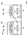
- FIGS. 4 to 6 further show at least one respective dryer 110, which is each downstream of one of the printing units 102a, 102b in the direction of the paper web 108 L.
- the direction of travel L of the paper web in the context of this invention does not define a global fixed plane in space, because the paper web 108 undergoes several changes of direction and possibly also wraps, such as Fig. 1 clearly shows. However, it is for the expert locally - ie for each web section of the paper web 108 - each a clear spatial direction from the local direction L of the paper web 108 determined.
- FIG. 4 now shows an embodiment in which each dryer 110 is structurally integrated into a printing unit 102a, 102b.
- Each dryer 110 can be structurally or spatially integrated into a printing unit 102a, 102b in such a way that the printing devices 109a, 109b, 109c, 109d are influenced by the dryer operation is avoided.
- each of the dryers 110 may be spatially disposed over the printing devices 109a, 109b, 109c, 109d of the respective printing unit 102a, 102b, as in FIG Fig. 6 shown. This avoids the risk that resulting heat rises and heats the pressure devices 109a, 109b, 109c, 109d in an undesired manner.
- the dryer 110 can also be arranged below the printing devices 109a, 109b, 109c, 109d of the respective printing unit 102a, 102b, as in FIG Fig. 5 shown.
- the inkjet printing devices 109, 109a, 109b, 109c, 109d or groups 119, 119a, 119b of printing devices 109, 109a, 109b, 109c, 109d are fixed transversely to the running direction L of the paper web 108 during the printing process .
- inkjet printing devices 109, 109a, 109b, 109c, 109d movement of the printing devices 109, 109a, 109b, 109c, 109d in the normal printing operation is unnecessary, and the number of moving parts is thereby significantly minimized.
- printing devices 109, 109a, 109b, 109c, 109d or groups 119, 119a, 119b of printing devices 109, 109a, 109b, 109c, 109d from a printing position by suitable bearings (eg eccentric or Lever) swiveled or slidably mounted by suitable bearings or guides (eg rails or plain bearings).
- suitable bearings eg eccentric or Lever
- suitable bearings or guides eg rails or plain bearings
- the printing devices 109 and a whole group 119 of printing devices 109 can extend across the full width of the paper web 108 transversely to the running direction L of the paper web 108.
- the various printing devices 109 serve to print different inks. However, it may also be provided only a single pressure device 109 over the full width of the paper web 108, as indicated by the dashed lines in the representation of the other printing devices 109. These are possible, but not necessarily mandatory.
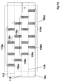
- FIGS. 8 to 15 show printing devices 109a, 109b, 109c, 109d or groups 119a, 119b, 119c, 119d of printing devices 109a, 109b, 109c, 109d transversely to the direction L of the paper web 108 each extend over only a portion of the width of the paper web 108. But then it is after the FIGS. 8 to 15 provided that printing devices 109a, 109b, 109c, 109d or groups 119a, 119b, 119c, 119d of printing devices 109a, 109b, 109c, 109d are arranged offset from each other transversely to the running direction L of the paper web 108.
- Typical paper web widths of web presses can be larger than 1 m, sometimes even significantly larger. If the printing devices extend transversely to the direction of travel of the paper web only over a part of the width of the paper web, but offset from one another, it can be dispensed on the one hand consuming and expensive full-width printing devices, on the other hand still the full paper web width are printed.
- FIGS. 8 to 10 show examples in which two printing devices 109a, 109b are provided, which can each print half a paper web width.
- the printing devices 109a, 109b do not necessarily have to print exactly half of the paper web width in each case. It can either be provided that printing devices 109a, 109b overlap in the running direction (L) of the paper web 108 transversely to the running direction L of the paper web 108 in at least one overlapping region 111. This overlapping area 111 is thus printed by both printing devices 109a, 109b, such as Fig. 9 shows.
- the printing devices 109a, 109b seen in the direction L of the paper web 108 are transverse to the direction L of the paper web 108 by at least one distance range 112 spaced from each other. In this distance range 112, therefore, neither of the two printing devices 109a, 109b prints.
- an overlapping area 111 or a spacing area 112 lies in each case in the region of a fold line 113, 114, 115 or in each case at least one such fold line 113, 114, 115 in an overlapping area 111 or a spacing area 112, as in FIGS Figures 9 and 10 shown.
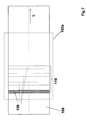
- FIGS. 7 . 11 to 13 and 15 show arrangements for printing multiple inks in a row. These are differentiated by different hatching. It is provided that in each case in the running direction L of the paper web 108 a plurality of printing devices 109, 109a, 109b, 109c, 109d - arranged in groups 119, 119a, 119b of printing devices 109, 109a, 109b, 109c, 109d - are arranged one behind the other. These groups result from the common printing of a portion of the paper web 108 and / or by a common control by the control device 20.
- FIG. 13 shows that the printing devices 109a, 109b, 109c, 109d may alternatively or additionally also transverse to the direction L of the paper web 108 each have a plurality of segments 129 for applying different printing inks. These are differentiated by different hatching.
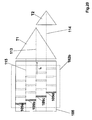
- FIG. 16 shows a folding apparatus 103 which is downstream of the printing units 102a, 102b or pressure units 102a, 102b can be arranged downstream and after Fig. 16 a plurality of, in the running direction L of the paper web 108 arranged in series Folding devices T1, T2 in the form of formers has.
- the folding devices T1, T2 are each arranged in a funnel module TM1, TM2.
- TM1, TM2 As in Fig. 25 will be explained, but in the context of the invention can also be dispensed with the folding devices T1, T2 or these can be at least bypassed.
- Folding apparatus 103 includes a web turning device 104, for example in the form of a turning bar device, a folding module 105 (in the execution of Fig. 25
- Cutting module 106 and display module 107 include the following components: a first train group 1 (driven in the example by a separate motor), a strand separation device 2, a second train group 3, a possibly optional cut register camera 4th for optically monitoring the operation and function of the cutting device 6 and for providing corresponding monitoring data to the control device (20), a small pulling group 5, a cutting device 6 with drive motor 28, a paper sheet transport element 131 in the form of a ribbon cable, a pivoting device 7 for the paper sheet transport element 131, a (on product length or print format) adjustable belt roller 8, a drive 9 for the ribbon cable 7, a device 10 for slowing down the transport movement of paper sheets B1, B2, B3 ... with a drive 11 and a ( on product length or print format) adjustable clamping point for the band roller.
- a first train group 1 driven in the example by a
- the folding module 105 is formed so that each folding device T1, T2 - ie each former - in at least one spatial direction R1, R2 is displaceable, wherein the first folding device T1 - ie the first former - in a first spatial direction R1 parallel to the plane ( Double arrow) is displaceable and the second folding device T2 - ie the second former - in a perpendicular spatial direction R2 perpendicular to the plane (arrowhead represented by circle with point, arrow end represented by circle with cross) is displaceable.
- a change in the width of the paper web 108 by moving the first folding device T1 - ie the first former - in the first spatial direction R1 parallel to the plane of the drawing are compensated so that the center of the folded paper web 108 again exactly on the fold line (dashed line ), which leads to the tip of the second folding device T2 - ie the second former - leads.
- the relative position and arrangement of the paper-sheet transport element 131 in the form of a ribbon cable does not have to be adapted to changed printing formats and paper web widths or paper web guides, as is the case with the DE 40 30 863 A1 the case is.
- Fig. 17 shows, in addition, the first folding device T1 - ie the first former - additionally in the second spatial direction R2 perpendicular to the plane (arrowhead represented by circle with point, arrow end represented by circle with cross) displaced.
- an asymmetric, that is, off-center web guide of the paper web can be compensated by the printing devices with simultaneous variability of the web widths and print formats by the biaxial displaceability, without the components 1 to 12 of downstream in the direction of the paper web 108 post-processing device 103a to changed print formats and paper web widths or paper web guides adapted (eg spatially shifted) must be. It can thus so for example instead of a full-width paper web 108 such as in Fig.
- the offset of the center of the paper web 108 against the center of the printing units 102a , 102b can then by moving the first folding device T1 - ie the first former - are compensated in the second spatial direction R2 perpendicular to the plane of the drawing.
- the folder 103 or the post-processing device 103a has a paper-sheet transport element 131 with a drive 9 - here in the form of a motor - on.
- the drive 9 is controlled or regulated in such a way by the control device 20 or a separate control device that separated by the cutting device 6 from the paper web 108 sheets of paper B1, B2, B3, B4, B5, B6 away from the remaining paper web 108 in the direction L of Paper web 108 are accelerated. This is in Fig. 24 shown.
- the paper sheet transport element 131 is then a device 10 with a drive 11 - downstream here - in the form of a motor.
- the drive 11 is controlled or regulated by the control device 20 or a separate control device in such a way that a slowing down of the transport movement of the previously accelerated paper sheets B1, B2, B3, B4, B5, B6 takes place.
- the device 10 is designed such that, in addition to the slowing down, raising or lowering of at least part of the paper sheets B1, B2, B3, B4, B5, B6 causes the paper sheets B1, B2, B3, B4, B5, B6 to flare up to achieve, as in Fig. 26 shown. This is done after Fig. 23 by a disc or roller 15, which has at least one cam 13 in the circumferential direction, which cooperates with a corresponding counter cam 14 of a corresponding counter-disc or counter-roller 17.
- Fig. 26 shows how the individual paper sheets B1, B2, B3, B4, B5, B6 are pushed together into a scale. Subsequently, this scale is compacted in a downstream collator into a stack of superimposed paper sheets 1... 6, for example into a book block and, if necessary, the side edges are then trimmed again to obtain a stack of individual sheets, for example in the form of a conventional one Buches as the final printed product of a letterpress production type. View X shows a top view of this stack. It shows in the example Fig. 26 each sheet has two printed pages. This corresponds to the result of a production type Fig. 21 ,
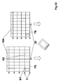
- Figures 21 and 22 show production modes with the aforementioned invention, in which a (full width) paper web 108 is cut by a slitter 26 for dividing the paper web 108 into partial webs TB and then successively over two formers (indicated by triangles) is guided, as in Fig. 16-20 shown. Each partial web TB is then subsequently cut by the cutting device 6 into paper sheets B1, B2.
Landscapes
- Engineering & Computer Science (AREA)
- Mechanical Engineering (AREA)
- Folding Of Thin Sheet-Like Materials, Special Discharging Devices, And Others (AREA)
- Handling Of Sheets (AREA)
- Rotary Presses (AREA)
Applications Claiming Priority (1)
| Application Number | Priority Date | Filing Date | Title |
|---|---|---|---|
| DE102009039278A DE102009039278A1 (de) | 2009-08-28 | 2009-08-28 | Formatvariable Rollendruckmaschine |
Publications (2)
| Publication Number | Publication Date |
|---|---|
| EP2305466A1 true EP2305466A1 (fr) | 2011-04-06 |
| EP2305466B1 EP2305466B1 (fr) | 2014-01-22 |
Family
ID=43499953
Family Applications (4)
| Application Number | Title | Priority Date | Filing Date |
|---|---|---|---|
| EP20100008454 Withdrawn EP2305468A1 (fr) | 2009-08-28 | 2010-08-13 | Presse rotative à format variable |
| EP20100008498 Active EP2305466B1 (fr) | 2009-08-28 | 2010-08-14 | Presse rotative à format variable |
| EP20100008499 Withdrawn EP2308684A1 (fr) | 2009-08-28 | 2010-08-14 | Presse rotative à format variable |
| EP10008872.3A Active EP2308681B1 (fr) | 2009-08-28 | 2010-08-26 | Dispositif a format variable pour decouper des produits imprimes ainsi que appareil de pliage et machine a imprimer avec un tel dispositif |
Family Applications Before (1)
| Application Number | Title | Priority Date | Filing Date |
|---|---|---|---|
| EP20100008454 Withdrawn EP2305468A1 (fr) | 2009-08-28 | 2010-08-13 | Presse rotative à format variable |
Family Applications After (2)
| Application Number | Title | Priority Date | Filing Date |
|---|---|---|---|
| EP20100008499 Withdrawn EP2308684A1 (fr) | 2009-08-28 | 2010-08-14 | Presse rotative à format variable |
| EP10008872.3A Active EP2308681B1 (fr) | 2009-08-28 | 2010-08-26 | Dispositif a format variable pour decouper des produits imprimes ainsi que appareil de pliage et machine a imprimer avec un tel dispositif |
Country Status (3)
| Country | Link |
|---|---|
| US (2) | US8827397B2 (fr) |
| EP (4) | EP2305468A1 (fr) |
| DE (2) | DE102009061056A1 (fr) |
Cited By (7)
| Publication number | Priority date | Publication date | Assignee | Title |
|---|---|---|---|---|
| DE102012103711A1 (de) * | 2012-04-27 | 2013-10-31 | Manroland Web Systems Gmbh | Querschneideeinrichtung einer Rollendruckmaschine |
| DE102014222316A1 (de) | 2014-10-31 | 2016-05-04 | Koenig & Bauer Ag | Produktionslinie sowie Verfahren zur Herstellung von Druckprodukten |
| DE102014222315A1 (de) | 2014-10-31 | 2016-05-04 | Koenig & Bauer Ag | Verfahren und Querhefteinrichtung zum Querheften von Heftgutabschnitten sowie Produktionslinie mit einer solchen Querhefteinrichtung |
| DE102014222314B3 (de) * | 2014-10-31 | 2016-05-04 | Koenig & Bauer Ag | Produktionslinie sowie Verfahren zur Herstellung von Druckprodukten |
| DE102014222317B3 (de) * | 2014-10-31 | 2016-05-04 | Koenig & Bauer Ag | Produktionslinie mit einem Weiterverarbeitungsabschnitt zur Verarbeitung bedruckten Bedruckstoffs |
| DE102014222319A1 (de) | 2014-10-31 | 2016-05-04 | Koenig & Bauer Ag | Produktionslinie sowie Verfahren zur Herstellung von Druckprodukten |
| US9855772B2 (en) | 2014-04-25 | 2018-01-02 | Koenig & Bauer Ag | Devices for post-processing web- or sheet-type stock, production line, and method for producing a printed product |
Families Citing this family (12)
| Publication number | Priority date | Publication date | Assignee | Title |
|---|---|---|---|---|
| JP2011157168A (ja) | 2010-01-29 | 2011-08-18 | Tokyo Kikai Seisakusho Ltd | 新聞製作装置 |
| JP5176155B2 (ja) * | 2010-11-11 | 2013-04-03 | 株式会社東京機械製作所 | 印刷物作成方法及び印刷物作成装置 |
| US20130019723A1 (en) * | 2011-07-22 | 2013-01-24 | Global Web Finishing | Printing system and method with variable rotary cutting capability |
| DE102013017224A1 (de) | 2013-10-17 | 2015-04-23 | Manroland Web Systems Gmbh | Verfahren und Vorrichtung zum Bearbeiten einer Bedruckstoffbahn |
| JP5762585B1 (ja) * | 2014-02-27 | 2015-08-12 | 三菱重工印刷紙工機械株式会社 | 印刷装置 |
| DE102014207835C5 (de) | 2014-04-25 | 2020-08-13 | Koenig & Bauer Ag | Verfahren und Druckmaschine zur Herstellung von Druckprodukten |
| US10960659B2 (en) * | 2014-07-02 | 2021-03-30 | Rotoprint Sovrastampa S.R.L. | System and method for overprinting on packages and/or containers of different formats |
| DE102014114731A1 (de) | 2014-10-10 | 2016-04-14 | Manroland Web Systems Gmbh | Verfahren zur Optimierung der Produktionsabfolge |
| JP6443164B2 (ja) * | 2015-03-24 | 2018-12-26 | セイコーエプソン株式会社 | 印刷データ生成装置、印刷装置、印刷データ生成方法およびプログラム |
| DE102016200481B4 (de) | 2016-01-15 | 2022-05-19 | Koenig & Bauer Ag | Vorrichtung und Verfahren zur Be- und/oder Verarbeitung bahnförmigen Bedruckstoffs |
| DE102016105317A1 (de) | 2016-03-22 | 2017-09-28 | Manroland Web Systems Gmbh | Verfahren zur Erzielung eines definierbaren Schuppenabstandes |
| DE102021132121A1 (de) | 2021-12-07 | 2023-06-07 | Koenig & Bauer Ag | Maschine sowie Verfahren zum Be- und/oder Verarbeiten von bahnförmigem Substrat |
Citations (3)
| Publication number | Priority date | Publication date | Assignee | Title |
|---|---|---|---|---|
| DE4030863A1 (de) | 1990-09-29 | 1992-04-09 | Roland Man Druckmasch | Rollenrotationsdruckmaschine fuer buecher- und kalenderdruck |
| US5117610A (en) * | 1990-09-21 | 1992-06-02 | Dittler Brothers, Incorporated | Methods and apparatus for printing and collating materials from multiple webs |
| US5906156A (en) * | 1997-04-17 | 1999-05-25 | Tokyo Kikai Seisakusho, Ltd. | Rotary press having additional printing apparatus |
Family Cites Families (46)
| Publication number | Priority date | Publication date | Assignee | Title |
|---|---|---|---|---|
| US4969640A (en) * | 1986-04-04 | 1990-11-13 | Littleton Industrial Consultants, Inc. | Sweet diverting and delivery system |
| JP2675565B2 (ja) * | 1988-01-11 | 1997-11-12 | 三菱重工業株式会社 | ピンレス折方法とその装置 |
| US4983155A (en) * | 1988-04-18 | 1991-01-08 | Stobb Inc. | Paper web cutter |
| DE3913112A1 (de) * | 1989-04-21 | 1990-10-25 | Roland Man Druckmasch | Laengsfalzvorrichtung |
| JP2755709B2 (ja) * | 1989-08-10 | 1998-05-25 | 三洋電機株式会社 | インクジェットプリンタ |
| DE4120628A1 (de) * | 1991-06-22 | 1992-12-24 | Roland Man Druckmasch | Einrichtung zum querschneiden und/oder -perforieren von bahnen |
| DE69311202T2 (de) * | 1992-04-23 | 1998-01-15 | Fujikura Ltd | Vorrichtung und Verfahren bei der Herstellung flexiblen Flachkabels durch Verbinden von Blattmaterial |
| DE9320795U1 (de) * | 1993-12-15 | 1995-02-02 | Albert-Frankenthal Ag, 67227 Frankenthal | Falzapparat |
| DE4344362C2 (de) * | 1993-12-24 | 1998-02-26 | Koenig & Bauer Albert Ag | Vorrichtung zum Herstellen von Falzprodukten |
| US5740709A (en) * | 1994-03-30 | 1998-04-21 | Goss Graphic Systems, Inc. | Two stage continuous web cutting system and method |
| US6024684A (en) * | 1995-11-08 | 2000-02-15 | Koenig & Bauer Aktiengesellschaft | Device for producing folded items |
| EP0868269A1 (fr) * | 1995-12-18 | 1998-10-07 | Patrick Wathieu | Coupeuse a papier a format variable |
| DE59604973D1 (de) * | 1995-12-27 | 2000-05-18 | Koenig & Bauer Ag | Falzapparat mit signaturweiche |
| US5683187A (en) | 1996-06-18 | 1997-11-04 | Scitex Digital Printing, Inc. | Digital color press platen assembly with pivoting platen frame |
| US6129346A (en) * | 1998-05-08 | 2000-10-10 | Morre U.S.A., Inc. | Method for forming a brochure attached to a periodical |
| DE19907357A1 (de) * | 1999-02-20 | 2000-08-24 | Bielomatik Leuze & Co | Querbearbeiter für Lagenmaterial, insbesondere Querschneider für Papier |
| US6360640B1 (en) | 1999-07-13 | 2002-03-26 | Heidelberger Druckmaschinen | Variable velocity cutting cylinders |
| US6684746B2 (en) * | 1999-12-02 | 2004-02-03 | Heidelberger Druckmaschinen Ag | Variable-length cut-off folder and method |
| DE10003025C1 (de) * | 2000-01-25 | 2001-05-23 | Koenig & Bauer Ag | Falzapparat |
| DE50007507D1 (de) * | 2000-11-25 | 2004-09-23 | Gerhard Kurt | Verfahren und Einrichtung zur Herstellung eines Druckerzeugnisses mit Druckwerk, Schneidwerk und Stapeleinheit |
| ES2216805T3 (es) * | 2000-11-28 | 2004-11-01 | Hunkeler Ag | Procedimiento y dispositivo para la fabricacion de un periodico. |
| DE10146923A1 (de) * | 2001-09-24 | 2003-04-10 | Heidelberger Druckmasch Ag | Vorrichtung zum rotativen Bearbeiten von blattförmigen Bedruckstoffen |
| US6820671B2 (en) * | 2001-10-05 | 2004-11-23 | Paragon Trade Brands, Inc. | Apparatus and method for assembling absorbent garments |
| US20030116041A1 (en) * | 2001-12-20 | 2003-06-26 | Delaware Capital Formation, Inc. | Moveable idler carriage for support of a web in relation to an array of inkjet printing devices |
| DE10213978A1 (de) | 2002-03-28 | 2003-10-09 | Roland Man Druckmasch | Verfahren zum Querschneiden einer laufenden Bahn |
| JP4022901B2 (ja) * | 2002-05-24 | 2007-12-19 | 株式会社ミヤコシ | 新聞の製作方法 |
| US6865864B2 (en) * | 2002-05-31 | 2005-03-15 | Robert E. Katz | Inline formed crossfold package and method |
| EP1449797A1 (fr) * | 2003-02-21 | 2004-08-25 | Kern Technologie und Handels GmbH | Procédé et appareil pour la traitement d'une bande de papier ou film |
| US20060191426A1 (en) * | 2003-06-03 | 2006-08-31 | Lee Timmerman | Bundled printed sheets |
| WO2006067117A1 (fr) * | 2004-12-20 | 2006-06-29 | Koenig & Bauer Aktiengesellschaft | Dispositif pour former une image a imprimer sur au moins un emplacement pour une image |
| EP1890884B1 (fr) * | 2005-05-30 | 2017-01-18 | Agfa Graphics Nv | Systeme d'impression comportant une table d'impression fixee de facon detachable a un module d'impression |
| US8141485B2 (en) * | 2005-08-18 | 2012-03-27 | Koenig & Bauer Aktiengesellschaft | Printing machine system |
| DE102005042345A1 (de) * | 2005-09-07 | 2007-03-08 | Man Roland Druckmaschinen Ag | Falzwerkoberteil |
| DE102005045041B3 (de) * | 2005-09-21 | 2007-02-01 | Koenig & Bauer Ag | Vorrichtung und ein Verfahren zur Verwendung einer Vorrichtung zum Einziehen mindestens einer Materialbahn bzw. mindestens eines Bahnstrangs in einen Falzapparat |
| DE502006002191D1 (de) * | 2005-12-15 | 2009-01-08 | Koenig & Bauer Ag | Druckmaschinenanlage |
| US8087746B2 (en) * | 2007-11-09 | 2012-01-03 | Hewlett-Packard Development Company, L.P. | Movable fluid receiver |
| US8038258B2 (en) * | 2007-11-09 | 2011-10-18 | Hewlett-Packard Development Company, L.P. | Print head service shuttle |
| US8220889B2 (en) * | 2007-11-09 | 2012-07-17 | Hewlett-Packard Development Company, L.P. | Web flow path |
| DE102007058957A1 (de) * | 2007-12-07 | 2009-06-10 | Heidelberger Druckmaschinen Ag | Verfahren zum Trocknen von bedrucktem Material |
| JP4691568B2 (ja) * | 2008-01-25 | 2011-06-01 | 株式会社東京機械製作所 | 連続紙用両面インクジェット印刷ユニット |
| JP4985434B2 (ja) * | 2008-01-29 | 2012-07-25 | Nkワークス株式会社 | デカール機構 |
| EP2123585B1 (fr) * | 2008-05-20 | 2012-09-26 | Hunkeler AG | Procédé et dispositif de traitement d'une bande de matériau déplacée imprimée |
| US8235484B2 (en) * | 2008-05-28 | 2012-08-07 | Ray Paul C | Printbar support mechanism |
| EP2291289B1 (fr) | 2008-05-29 | 2020-09-16 | Hewlett-Packard Development Company, L.P. | Imprimante comprenant des unités d impression positionnables |
| US8042910B2 (en) * | 2008-05-29 | 2011-10-25 | Hewlett-Packard Development Company, L.P. | Replaceable printbar assembly |
| US20100101386A1 (en) * | 2008-10-29 | 2010-04-29 | Goss International Americas, Inc. | Variable signature length web cutting apparatus |
-
2009
- 2009-08-28 DE DE102009061056A patent/DE102009061056A1/de not_active Withdrawn
- 2009-08-28 DE DE102009039278A patent/DE102009039278A1/de not_active Withdrawn
- 2009-09-08 US US12/555,016 patent/US8827397B2/en active Active
-
2010
- 2010-08-13 EP EP20100008454 patent/EP2305468A1/fr not_active Withdrawn
- 2010-08-14 EP EP20100008498 patent/EP2305466B1/fr active Active
- 2010-08-14 EP EP20100008499 patent/EP2308684A1/fr not_active Withdrawn
- 2010-08-25 US US12/862,826 patent/US20110058885A1/en not_active Abandoned
- 2010-08-26 EP EP10008872.3A patent/EP2308681B1/fr active Active
Patent Citations (3)
| Publication number | Priority date | Publication date | Assignee | Title |
|---|---|---|---|---|
| US5117610A (en) * | 1990-09-21 | 1992-06-02 | Dittler Brothers, Incorporated | Methods and apparatus for printing and collating materials from multiple webs |
| DE4030863A1 (de) | 1990-09-29 | 1992-04-09 | Roland Man Druckmasch | Rollenrotationsdruckmaschine fuer buecher- und kalenderdruck |
| US5906156A (en) * | 1997-04-17 | 1999-05-25 | Tokyo Kikai Seisakusho, Ltd. | Rotary press having additional printing apparatus |
Non-Patent Citations (3)
| Title |
|---|
| HELMUT TESCHNER, OFFSETDRUCKTECHNIK, 1997, pages 10,76 |
| HELMUT TESCHNER, OFFSETDRUCKTECHNIK, 1997, pages 10,76 - 10,82 |
| WOLFGANG WALENSKI, ROLLENOFFSETDRUCK, 1995, pages 98 - 103 |
Cited By (13)
| Publication number | Priority date | Publication date | Assignee | Title |
|---|---|---|---|---|
| DE102012103711B4 (de) * | 2012-04-27 | 2021-04-01 | Manroland Goss Web Systems Gmbh | Querschneideeinrichtung einer Rollendruckmaschine |
| DE102012103711A1 (de) * | 2012-04-27 | 2013-10-31 | Manroland Web Systems Gmbh | Querschneideeinrichtung einer Rollendruckmaschine |
| US9855772B2 (en) | 2014-04-25 | 2018-01-02 | Koenig & Bauer Ag | Devices for post-processing web- or sheet-type stock, production line, and method for producing a printed product |
| EP3134263B1 (fr) | 2014-04-25 | 2020-03-11 | Koenig & Bauer AG | Ligne de production pour la fabrication de produits d'impression |
| DE102014222314B3 (de) * | 2014-10-31 | 2016-05-04 | Koenig & Bauer Ag | Produktionslinie sowie Verfahren zur Herstellung von Druckprodukten |
| DE102014222319A1 (de) | 2014-10-31 | 2016-05-04 | Koenig & Bauer Ag | Produktionslinie sowie Verfahren zur Herstellung von Druckprodukten |
| DE102014222316B4 (de) * | 2014-10-31 | 2016-05-12 | Koenig & Bauer Ag | Produktionslinie sowie Verfahren zur Herstellung von Druckprodukten |
| DE102014222317B3 (de) * | 2014-10-31 | 2016-05-04 | Koenig & Bauer Ag | Produktionslinie mit einem Weiterverarbeitungsabschnitt zur Verarbeitung bedruckten Bedruckstoffs |
| DE102014222315B4 (de) | 2014-10-31 | 2019-06-06 | Koenig & Bauer Ag | Verfahren und Querhefteinrichtung zum Querheften von Heftgutabschnitten sowie Produktionslinie mit einer solchen Querhefteinrichtung |
| DE102014222315A1 (de) | 2014-10-31 | 2016-05-04 | Koenig & Bauer Ag | Verfahren und Querhefteinrichtung zum Querheften von Heftgutabschnitten sowie Produktionslinie mit einer solchen Querhefteinrichtung |
| DE102014222316A1 (de) | 2014-10-31 | 2016-05-04 | Koenig & Bauer Ag | Produktionslinie sowie Verfahren zur Herstellung von Druckprodukten |
| DE102014222319B4 (de) * | 2014-10-31 | 2021-04-29 | Koenig & Bauer Ag | Produktionslinie mit einer Druckmaschine |
| DE102014222317C5 (de) | 2014-10-31 | 2022-10-27 | Koenig & Bauer Ag | Produktionslinie mit einem Weiterverarbeitungsabschnitt zur Verarbeitung bedruckten Bedruckstoffs |
Also Published As
| Publication number | Publication date |
|---|---|
| EP2305468A1 (fr) | 2011-04-06 |
| EP2308684A1 (fr) | 2011-04-13 |
| EP2305466B1 (fr) | 2014-01-22 |
| EP2308681B1 (fr) | 2023-10-04 |
| DE102009061056A1 (de) | 2011-06-16 |
| EP2308681A3 (fr) | 2011-09-28 |
| EP2308681A2 (fr) | 2011-04-13 |
| US20110050767A1 (en) | 2011-03-03 |
| US20110058885A1 (en) | 2011-03-10 |
| US8827397B2 (en) | 2014-09-09 |
| DE102009039278A1 (de) | 2011-06-01 |
Similar Documents
| Publication | Publication Date | Title |
|---|---|---|
| EP2305466B1 (fr) | Presse rotative à format variable | |
| EP1556301B1 (fr) | Dispositifs pour traiter et/ou acheminer une bande de matiere | |
| EP1742796B1 (fr) | Presses rotatives a imprimer | |
| EP2199084B1 (fr) | Dispositif et procédé de fabrication de blocs de livres | |
| EP2293940B1 (fr) | Presse offset rotative et procédé pour faire fonctionner la presse offset rotative | |
| EP1742794B1 (fr) | Presse rotative d'impression avec une unite d'impression comprenant un cylindre de plaques pour l'impression d'une triple largeur au moins | |
| EP1590283A1 (fr) | Machine a imprimer comprenant au moins un groupe d'impression, un appareil de pliage et au moins un niveau de retournement et de melange | |
| EP1742793A1 (fr) | Groupe d'impression offset d'une imprimeuse destinee a l'impression de journaux | |
| DE102010003363B4 (de) | Rollenoffsetdruckmaschine und Verfahren zur Herstellung eines Produktes | |
| EP2727868A1 (fr) | Dispositif et procédé destinés à plier des feuilles imprimées | |
| EP1871602B1 (fr) | Machine d'impression | |
| DE102009061058A1 (de) | Formatvariable Rollendruckmaschine | |
| EP2319788A1 (fr) | Plieuse dotée d'un dispositif d'extraction | |
| DE102008002056A1 (de) | Rollenoffsetdruckmaschine sowie Verfahren zum Betrieb der Rollenoffsetdruckmaschine | |
| DE10003107B4 (de) | Verfahren und Vorrichtung für einen Transport einer Bedruckstoffbahn zwischen Funktionseinheiten einer Rotationsdruckmaschine in besonderen Betriebssituationen | |
| EP1908588A2 (fr) | Machine d'impression rotative avec une unité d'impression comprenant un cylindre de plaques | |
| DE102013201901B4 (de) | Verfahren und Vorrichtung zur Herstellung eines mehrlagigen Druckproduktes sowie Druckmaschine | |
| DE102011106094A1 (de) | Verfahren zur Herstellung eines Druckproduktes | |
| CH704936B1 (de) | Verfahren zur Herstellung eines Druckproduktes. |
Legal Events
| Date | Code | Title | Description |
|---|---|---|---|
| PUAI | Public reference made under article 153(3) epc to a published international application that has entered the european phase |
Free format text: ORIGINAL CODE: 0009012 |
|
| AK | Designated contracting states |
Kind code of ref document: A1 Designated state(s): AL AT BE BG CH CY CZ DE DK EE ES FI FR GB GR HR HU IE IS IT LI LT LU LV MC MK MT NL NO PL PT RO SE SI SK SM TR |
|
| AX | Request for extension of the european patent |
Extension state: BA ME RS |
|
| REG | Reference to a national code |
Ref country code: DE Ref legal event code: R079 Ref document number: 502010005993 Country of ref document: DE Free format text: PREVIOUS MAIN CLASS: B41F0013540000 Ipc: B65H0045060000 |
|
| 17P | Request for examination filed |
Effective date: 20111004 |
|
| GRAP | Despatch of communication of intention to grant a patent |
Free format text: ORIGINAL CODE: EPIDOSNIGR1 |
|
| RIC1 | Information provided on ipc code assigned before grant |
Ipc: B41J 25/316 20060101ALI20111026BHEP Ipc: B65H 45/10 20060101ALI20111026BHEP Ipc: B41J 11/20 20060101ALI20111026BHEP Ipc: B41J 15/04 20060101ALI20111026BHEP Ipc: B41J 11/66 20060101ALI20111026BHEP Ipc: B41J 3/60 20060101ALI20111026BHEP Ipc: B41F 23/04 20060101ALI20111026BHEP Ipc: B41F 17/02 20060101ALI20111026BHEP Ipc: B65H 45/08 20060101ALI20111026BHEP Ipc: B65H 45/06 20060101AFI20111026BHEP Ipc: B41F 11/00 20060101ALI20111026BHEP Ipc: B65H 35/04 20060101ALI20111026BHEP Ipc: B65H 35/02 20060101ALI20111026BHEP |
|
| 19U | Interruption of proceedings before grant |
Effective date: 20120201 |
|
| 19W | Proceedings resumed before grant after interruption of proceedings |
Effective date: 20130902 |
|
| RAP1 | Party data changed (applicant data changed or rights of an application transferred) |
Owner name: MANROLAND WEB SYSTEMS GMBH |
|
| GRAS | Grant fee paid |
Free format text: ORIGINAL CODE: EPIDOSNIGR3 |
|
| GRAA | (expected) grant |
Free format text: ORIGINAL CODE: 0009210 |
|
| AK | Designated contracting states |
Kind code of ref document: B1 Designated state(s): AL AT BE BG CH CY CZ DE DK EE ES FI FR GB GR HR HU IE IS IT LI LT LU LV MC MK MT NL NO PL PT RO SE SI SK SM TR |
|
| REG | Reference to a national code |
Ref country code: GB Ref legal event code: FG4D Free format text: NOT ENGLISH |
|
| REG | Reference to a national code |
Ref country code: CH Ref legal event code: NV Representative=s name: E. BLUM AND CO. AG PATENT- UND MARKENANWAELTE , CH Ref country code: CH Ref legal event code: EP |
|
| REG | Reference to a national code |
Ref country code: AT Ref legal event code: REF Ref document number: 650697 Country of ref document: AT Kind code of ref document: T Effective date: 20140215 |
|
| REG | Reference to a national code |
Ref country code: IE Ref legal event code: FG4D Free format text: LANGUAGE OF EP DOCUMENT: GERMAN |
|
| REG | Reference to a national code |
Ref country code: DE Ref legal event code: R096 Ref document number: 502010005993 Country of ref document: DE Effective date: 20140227 |
|
| REG | Reference to a national code |
Ref country code: NL Ref legal event code: VDEP Effective date: 20140122 |
|
| REG | Reference to a national code |
Ref country code: LT Ref legal event code: MG4D |
|
| PG25 | Lapsed in a contracting state [announced via postgrant information from national office to epo] |
Ref country code: IS Free format text: LAPSE BECAUSE OF FAILURE TO SUBMIT A TRANSLATION OF THE DESCRIPTION OR TO PAY THE FEE WITHIN THE PRESCRIBED TIME-LIMIT Effective date: 20140522 Ref country code: NO Free format text: LAPSE BECAUSE OF FAILURE TO SUBMIT A TRANSLATION OF THE DESCRIPTION OR TO PAY THE FEE WITHIN THE PRESCRIBED TIME-LIMIT Effective date: 20140422 Ref country code: LT Free format text: LAPSE BECAUSE OF FAILURE TO SUBMIT A TRANSLATION OF THE DESCRIPTION OR TO PAY THE FEE WITHIN THE PRESCRIBED TIME-LIMIT Effective date: 20140122 |
|
| PG25 | Lapsed in a contracting state [announced via postgrant information from national office to epo] |
Ref country code: FI Free format text: LAPSE BECAUSE OF FAILURE TO SUBMIT A TRANSLATION OF THE DESCRIPTION OR TO PAY THE FEE WITHIN THE PRESCRIBED TIME-LIMIT Effective date: 20140122 Ref country code: ES Free format text: LAPSE BECAUSE OF FAILURE TO SUBMIT A TRANSLATION OF THE DESCRIPTION OR TO PAY THE FEE WITHIN THE PRESCRIBED TIME-LIMIT Effective date: 20140122 Ref country code: CY Free format text: LAPSE BECAUSE OF FAILURE TO SUBMIT A TRANSLATION OF THE DESCRIPTION OR TO PAY THE FEE WITHIN THE PRESCRIBED TIME-LIMIT Effective date: 20140122 Ref country code: NL Free format text: LAPSE BECAUSE OF FAILURE TO SUBMIT A TRANSLATION OF THE DESCRIPTION OR TO PAY THE FEE WITHIN THE PRESCRIBED TIME-LIMIT Effective date: 20140122 Ref country code: SE Free format text: LAPSE BECAUSE OF FAILURE TO SUBMIT A TRANSLATION OF THE DESCRIPTION OR TO PAY THE FEE WITHIN THE PRESCRIBED TIME-LIMIT Effective date: 20140122 Ref country code: PT Free format text: LAPSE BECAUSE OF FAILURE TO SUBMIT A TRANSLATION OF THE DESCRIPTION OR TO PAY THE FEE WITHIN THE PRESCRIBED TIME-LIMIT Effective date: 20140522 |
|
| PG25 | Lapsed in a contracting state [announced via postgrant information from national office to epo] |
Ref country code: LV Free format text: LAPSE BECAUSE OF FAILURE TO SUBMIT A TRANSLATION OF THE DESCRIPTION OR TO PAY THE FEE WITHIN THE PRESCRIBED TIME-LIMIT Effective date: 20140122 Ref country code: HR Free format text: LAPSE BECAUSE OF FAILURE TO SUBMIT A TRANSLATION OF THE DESCRIPTION OR TO PAY THE FEE WITHIN THE PRESCRIBED TIME-LIMIT Effective date: 20140122 |
|
| REG | Reference to a national code |
Ref country code: DE Ref legal event code: R097 Ref document number: 502010005993 Country of ref document: DE |
|
| PG25 | Lapsed in a contracting state [announced via postgrant information from national office to epo] |
Ref country code: DK Free format text: LAPSE BECAUSE OF FAILURE TO SUBMIT A TRANSLATION OF THE DESCRIPTION OR TO PAY THE FEE WITHIN THE PRESCRIBED TIME-LIMIT Effective date: 20140122 Ref country code: CZ Free format text: LAPSE BECAUSE OF FAILURE TO SUBMIT A TRANSLATION OF THE DESCRIPTION OR TO PAY THE FEE WITHIN THE PRESCRIBED TIME-LIMIT Effective date: 20140122 Ref country code: RO Free format text: LAPSE BECAUSE OF FAILURE TO SUBMIT A TRANSLATION OF THE DESCRIPTION OR TO PAY THE FEE WITHIN THE PRESCRIBED TIME-LIMIT Effective date: 20140122 Ref country code: EE Free format text: LAPSE BECAUSE OF FAILURE TO SUBMIT A TRANSLATION OF THE DESCRIPTION OR TO PAY THE FEE WITHIN THE PRESCRIBED TIME-LIMIT Effective date: 20140122 |
|
| PG25 | Lapsed in a contracting state [announced via postgrant information from national office to epo] |
Ref country code: SK Free format text: LAPSE BECAUSE OF FAILURE TO SUBMIT A TRANSLATION OF THE DESCRIPTION OR TO PAY THE FEE WITHIN THE PRESCRIBED TIME-LIMIT Effective date: 20140122 Ref country code: PL Free format text: LAPSE BECAUSE OF FAILURE TO SUBMIT A TRANSLATION OF THE DESCRIPTION OR TO PAY THE FEE WITHIN THE PRESCRIBED TIME-LIMIT Effective date: 20140122 |
|
| PLBE | No opposition filed within time limit |
Free format text: ORIGINAL CODE: 0009261 |
|
| STAA | Information on the status of an ep patent application or granted ep patent |
Free format text: STATUS: NO OPPOSITION FILED WITHIN TIME LIMIT |
|
| 26N | No opposition filed |
Effective date: 20141023 |
|
| REG | Reference to a national code |
Ref country code: DE Ref legal event code: R097 Ref document number: 502010005993 Country of ref document: DE Effective date: 20141023 |
|
| PG25 | Lapsed in a contracting state [announced via postgrant information from national office to epo] |
Ref country code: LU Free format text: LAPSE BECAUSE OF FAILURE TO SUBMIT A TRANSLATION OF THE DESCRIPTION OR TO PAY THE FEE WITHIN THE PRESCRIBED TIME-LIMIT Effective date: 20140814 Ref country code: MC Free format text: LAPSE BECAUSE OF FAILURE TO SUBMIT A TRANSLATION OF THE DESCRIPTION OR TO PAY THE FEE WITHIN THE PRESCRIBED TIME-LIMIT Effective date: 20140122 |
|
| PG25 | Lapsed in a contracting state [announced via postgrant information from national office to epo] |
Ref country code: BE Free format text: LAPSE BECAUSE OF NON-PAYMENT OF DUE FEES Effective date: 20140831 |
|
| REG | Reference to a national code |
Ref country code: IE Ref legal event code: MM4A |
|
| PG25 | Lapsed in a contracting state [announced via postgrant information from national office to epo] |
Ref country code: SI Free format text: LAPSE BECAUSE OF FAILURE TO SUBMIT A TRANSLATION OF THE DESCRIPTION OR TO PAY THE FEE WITHIN THE PRESCRIBED TIME-LIMIT Effective date: 20140122 |
|
| PG25 | Lapsed in a contracting state [announced via postgrant information from national office to epo] |
Ref country code: IE Free format text: LAPSE BECAUSE OF NON-PAYMENT OF DUE FEES Effective date: 20140814 |
|
| PG25 | Lapsed in a contracting state [announced via postgrant information from national office to epo] |
Ref country code: SM Free format text: LAPSE BECAUSE OF FAILURE TO SUBMIT A TRANSLATION OF THE DESCRIPTION OR TO PAY THE FEE WITHIN THE PRESCRIBED TIME-LIMIT Effective date: 20140122 |
|
| PG25 | Lapsed in a contracting state [announced via postgrant information from national office to epo] |
Ref country code: GR Free format text: LAPSE BECAUSE OF FAILURE TO SUBMIT A TRANSLATION OF THE DESCRIPTION OR TO PAY THE FEE WITHIN THE PRESCRIBED TIME-LIMIT Effective date: 20140423 Ref country code: IT Free format text: LAPSE BECAUSE OF FAILURE TO SUBMIT A TRANSLATION OF THE DESCRIPTION OR TO PAY THE FEE WITHIN THE PRESCRIBED TIME-LIMIT Effective date: 20140122 Ref country code: BG Free format text: LAPSE BECAUSE OF FAILURE TO SUBMIT A TRANSLATION OF THE DESCRIPTION OR TO PAY THE FEE WITHIN THE PRESCRIBED TIME-LIMIT Effective date: 20140122 Ref country code: MT Free format text: LAPSE BECAUSE OF FAILURE TO SUBMIT A TRANSLATION OF THE DESCRIPTION OR TO PAY THE FEE WITHIN THE PRESCRIBED TIME-LIMIT Effective date: 20140122 |
|
| PG25 | Lapsed in a contracting state [announced via postgrant information from national office to epo] |
Ref country code: HU Free format text: LAPSE BECAUSE OF FAILURE TO SUBMIT A TRANSLATION OF THE DESCRIPTION OR TO PAY THE FEE WITHIN THE PRESCRIBED TIME-LIMIT; INVALID AB INITIO Effective date: 20100814 Ref country code: TR Free format text: LAPSE BECAUSE OF FAILURE TO SUBMIT A TRANSLATION OF THE DESCRIPTION OR TO PAY THE FEE WITHIN THE PRESCRIBED TIME-LIMIT Effective date: 20140122 |
|
| REG | Reference to a national code |
Ref country code: FR Ref legal event code: PLFP Year of fee payment: 7 |
|
| REG | Reference to a national code |
Ref country code: AT Ref legal event code: MM01 Ref document number: 650697 Country of ref document: AT Kind code of ref document: T Effective date: 20150814 |
|
| PG25 | Lapsed in a contracting state [announced via postgrant information from national office to epo] |
Ref country code: AT Free format text: LAPSE BECAUSE OF NON-PAYMENT OF DUE FEES Effective date: 20150814 |
|
| REG | Reference to a national code |
Ref country code: FR Ref legal event code: PLFP Year of fee payment: 8 |
|
| PG25 | Lapsed in a contracting state [announced via postgrant information from national office to epo] |
Ref country code: MK Free format text: LAPSE BECAUSE OF FAILURE TO SUBMIT A TRANSLATION OF THE DESCRIPTION OR TO PAY THE FEE WITHIN THE PRESCRIBED TIME-LIMIT Effective date: 20140122 |
|
| REG | Reference to a national code |
Ref country code: FR Ref legal event code: PLFP Year of fee payment: 9 |
|
| PG25 | Lapsed in a contracting state [announced via postgrant information from national office to epo] |
Ref country code: AL Free format text: LAPSE BECAUSE OF FAILURE TO SUBMIT A TRANSLATION OF THE DESCRIPTION OR TO PAY THE FEE WITHIN THE PRESCRIBED TIME-LIMIT Effective date: 20140122 |
|
| REG | Reference to a national code |
Ref country code: DE Ref legal event code: R081 Ref document number: 502010005993 Country of ref document: DE Owner name: MANROLAND GOSS WEB SYSTEMS GMBH, DE Free format text: FORMER OWNER: MANROLAND WEB SYSTEMS GMBH, 86153 AUGSBURG, DE |
|
| PGFP | Annual fee paid to national office [announced via postgrant information from national office to epo] |
Ref country code: SE Payment date: 20181211 Year of fee payment: 10 |
|
| GBPC | Gb: european patent ceased through non-payment of renewal fee |
Effective date: 20190814 |
|
| PG25 | Lapsed in a contracting state [announced via postgrant information from national office to epo] |
Ref country code: FR Free format text: LAPSE BECAUSE OF NON-PAYMENT OF DUE FEES Effective date: 20190831 |
|
| PG25 | Lapsed in a contracting state [announced via postgrant information from national office to epo] |
Ref country code: GB Free format text: LAPSE BECAUSE OF NON-PAYMENT OF DUE FEES Effective date: 20190814 |
|
| PGFP | Annual fee paid to national office [announced via postgrant information from national office to epo] |
Ref country code: DE Payment date: 20250820 Year of fee payment: 16 |
|
| PGFP | Annual fee paid to national office [announced via postgrant information from national office to epo] |
Ref country code: CH Payment date: 20250901 Year of fee payment: 16 |