EP3135342A1 - Rideau coupe-feu ou pare-fumees - Google Patents
Rideau coupe-feu ou pare-fumees Download PDFInfo
- Publication number
- EP3135342A1 EP3135342A1 EP16184338.8A EP16184338A EP3135342A1 EP 3135342 A1 EP3135342 A1 EP 3135342A1 EP 16184338 A EP16184338 A EP 16184338A EP 3135342 A1 EP3135342 A1 EP 3135342A1
- Authority
- EP
- European Patent Office
- Prior art keywords
- fire
- protection element
- guide rail
- fire protection
- smoke
- Prior art date
- Legal status (The legal status is an assumption and is not a legal conclusion. Google has not performed a legal analysis and makes no representation as to the accuracy of the status listed.)
- Withdrawn
Links
Images




Classifications
-
- E—FIXED CONSTRUCTIONS
- E04—BUILDING
- E04B—GENERAL BUILDING CONSTRUCTIONS; WALLS, e.g. PARTITIONS; ROOFS; FLOORS; CEILINGS; INSULATION OR OTHER PROTECTION OF BUILDINGS
- E04B1/00—Constructions in general; Structures which are not restricted either to walls, e.g. partitions, or floors or ceilings or roofs
- E04B1/62—Insulation or other protection; Elements or use of specified material therefor
- E04B1/92—Protection against other undesired influences or dangers
- E04B1/94—Protection against other undesired influences or dangers against fire
- E04B1/947—Protection against other undesired influences or dangers against fire by closing openings in walls or the like in the case of fire
-
- A—HUMAN NECESSITIES
- A62—LIFE-SAVING; FIRE-FIGHTING
- A62C—FIRE-FIGHTING
- A62C2/00—Fire prevention or containment
- A62C2/06—Physical fire-barriers
- A62C2/10—Fire-proof curtains
-
- A—HUMAN NECESSITIES
- A62—LIFE-SAVING; FIRE-FIGHTING
- A62C—FIRE-FIGHTING
- A62C3/00—Fire prevention, containment or extinguishing specially adapted for particular objects or places
- A62C3/14—Fire prevention, containment or extinguishing specially adapted for particular objects or places in connection with doors, windows, ventilators, partitions, or shutters, e.g. automatic closing
-
- E—FIXED CONSTRUCTIONS
- E04—BUILDING
- E04B—GENERAL BUILDING CONSTRUCTIONS; WALLS, e.g. PARTITIONS; ROOFS; FLOORS; CEILINGS; INSULATION OR OTHER PROTECTION OF BUILDINGS
- E04B1/00—Constructions in general; Structures which are not restricted either to walls, e.g. partitions, or floors or ceilings or roofs
- E04B1/62—Insulation or other protection; Elements or use of specified material therefor
- E04B1/92—Protection against other undesired influences or dangers
- E04B1/94—Protection against other undesired influences or dangers against fire
- E04B1/946—Protection against smoke or toxic gases
-
- E—FIXED CONSTRUCTIONS
- E04—BUILDING
- E04B—GENERAL BUILDING CONSTRUCTIONS; WALLS, e.g. PARTITIONS; ROOFS; FLOORS; CEILINGS; INSULATION OR OTHER PROTECTION OF BUILDINGS
- E04B1/00—Constructions in general; Structures which are not restricted either to walls, e.g. partitions, or floors or ceilings or roofs
- E04B1/62—Insulation or other protection; Elements or use of specified material therefor
- E04B1/92—Protection against other undesired influences or dangers
- E04B1/94—Protection against other undesired influences or dangers against fire
- E04B1/948—Fire-proof sealings or joints
-
- E—FIXED CONSTRUCTIONS
- E05—LOCKS; KEYS; WINDOW OR DOOR FITTINGS; SAFES
- E05D—HINGES OR SUSPENSION DEVICES FOR DOORS, WINDOWS OR WINGS
- E05D15/00—Suspension arrangements for wings
-
- E—FIXED CONSTRUCTIONS
- E06—DOORS, WINDOWS, SHUTTERS, OR ROLLER BLINDS IN GENERAL; LADDERS
- E06B—FIXED OR MOVABLE CLOSURES FOR OPENINGS IN BUILDINGS, VEHICLES, FENCES OR LIKE ENCLOSURES IN GENERAL, e.g. DOORS, WINDOWS, BLINDS, GATES
- E06B5/00—Doors, windows, or like closures for special purposes; Border constructions therefor
- E06B5/10—Doors, windows, or like closures for special purposes; Border constructions therefor for protection against air-raid or other war-like action; for other protective purposes
- E06B5/16—Fireproof doors or similar closures; Adaptations of fixed constructions therefor
- E06B5/164—Sealing arrangements between the door or window and its frame, e.g. intumescent seals specially adapted therefor
-
- E—FIXED CONSTRUCTIONS
- E06—DOORS, WINDOWS, SHUTTERS, OR ROLLER BLINDS IN GENERAL; LADDERS
- E06B—FIXED OR MOVABLE CLOSURES FOR OPENINGS IN BUILDINGS, VEHICLES, FENCES OR LIKE ENCLOSURES IN GENERAL, e.g. DOORS, WINDOWS, BLINDS, GATES
- E06B9/00—Screening or protective devices for wall or similar openings, with or without operating or securing mechanisms; Closures of similar construction
- E06B9/56—Operating, guiding or securing devices or arrangements for roll-type closures; Spring drums; Tape drums; Counterweighting arrangements therefor
- E06B9/58—Guiding devices
- E06B9/581—Means to prevent or induce disengagement of shutter from side rails
-
- E—FIXED CONSTRUCTIONS
- E06—DOORS, WINDOWS, SHUTTERS, OR ROLLER BLINDS IN GENERAL; LADDERS
- E06B—FIXED OR MOVABLE CLOSURES FOR OPENINGS IN BUILDINGS, VEHICLES, FENCES OR LIKE ENCLOSURES IN GENERAL, e.g. DOORS, WINDOWS, BLINDS, GATES
- E06B9/00—Screening or protective devices for wall or similar openings, with or without operating or securing mechanisms; Closures of similar construction
- E06B9/56—Operating, guiding or securing devices or arrangements for roll-type closures; Spring drums; Tape drums; Counterweighting arrangements therefor
- E06B9/68—Operating devices or mechanisms, e.g. with electric drive
-
- E—FIXED CONSTRUCTIONS
- E06—DOORS, WINDOWS, SHUTTERS, OR ROLLER BLINDS IN GENERAL; LADDERS
- E06B—FIXED OR MOVABLE CLOSURES FOR OPENINGS IN BUILDINGS, VEHICLES, FENCES OR LIKE ENCLOSURES IN GENERAL, e.g. DOORS, WINDOWS, BLINDS, GATES
- E06B9/00—Screening or protective devices for wall or similar openings, with or without operating or securing mechanisms; Closures of similar construction
- E06B9/56—Operating, guiding or securing devices or arrangements for roll-type closures; Spring drums; Tape drums; Counterweighting arrangements therefor
- E06B9/68—Operating devices or mechanisms, e.g. with electric drive
- E06B2009/6809—Control
- E06B2009/6818—Control using sensors
- E06B2009/6836—Control using sensors sensing obstacle
Definitions
- the invention relates to a fire or smoke protection curtain with (a) a textile fire protection element having a first side in the form of a front and a second side in the form of a back, in a compact bearing assembly and a protection arrangement in which there is the spread of a fire and / or opposes smoke, is engageable and extends in the protective arrangement along a closing surface, and (b) at least one guide rail which guides the fire protection element when the fire protection element is in the protective arrangement and for applying a holding force corresponding to bulging of the Fire protection element counteracts, is formed.
- Such fire or smoke curtains are used to inhibit the spread of smoke and / or fire. Often fire or smoke curtains are used to close an opening in a wall in case of fire. If a compressed air difference arises between the front side and the rear side of the fire protection element, the at least one guide rail must apply a holding force. The holding force therefore counteracts excessive bulging of the fire protection element.
- the back is, for example, the wall side of the fire protection element.
- a fire or smoke curtain which is arranged in front of a door and in which a ballast strip on the foot portion of the fire protection element is used to pull the fire protection element in case of fire down in front of the door.
- the baseboard and the fire protection element run in an S-shaped guide rail.
- Windab gleichvorhang known, which is formed so that the curtain element slips out of the guide rails when a critical wind load is exceeded. Such behavior is unacceptable in a fire or smoke curtain because it contradicts its protective function.
- the invention is based on the object to reduce disadvantages in the prior art.
- the invention solves the problem by a generic fire or smoke protection curtain, wherein the guide rail is formed for applying the holding force of only one of the sides of the fire protection element.
- the guide rail can be very compact, that is space-saving, can be formed. Looking at guide rails according to the prior art along the closing surface, the guide rail extends both on the first side and on the second side of the fire protection element. A guide rail of the invention or fire On the other hand, the smoke protection curtain only has to extend on one side of the fire protection element. In other words, if one looks along the fire protection element, guide rails according to the prior art always have to see part of the guide rail on both sides of the fire protection element. In the case of a guide rail according to the invention, only part of the guide rail has to be on one side of the fire protection textile be seen. It should be noted that it is also possible that the fire or smoke curtain has more than one guide rail. In particular, it is advantageous that the guide rail can be built flat. The holding force is preferably applied from the wall side to the fire protection element.
- a guide rail according to the invention is particularly easy to manufacture. Although it is possible and represents a preferred embodiment, that the guide rail has a Kederstange, but this is unnecessary. An inventive fire or smoke protection curtain is therefore easy to install.
- the special embodiment of the guide rail permits close monitoring by means of a light grid in a simple manner.
- Light grids are formed by a plurality of spatially spaced light beams.
- An interruption of at least one of the light beams is detected by an interruption detection device, which according to an embodiment of the invention is part of the fire or smoke protection curtain and has a light grid generating device for generating the light grid.
- an interruption detection device which according to an embodiment of the invention is part of the fire or smoke protection curtain and has a light grid generating device for generating the light grid.
- the textile fire protection element on the guide rail is deflected out of the closing plane.
- the resulting change of direction and the associated load change direction allow for structurally smaller holding elements and / or thinner Keder rods.
- the guide rail can be realized with smaller dimensions than before.
- a guide rail with smaller dimensions is relative to previous guide rails stiffer and less prone to decay in case of fire as well as saving material and space.
- the change of direction also results in a continuous and reliable sealing on at least one (usually two) contact edge of the guide rail, resulting in a smoke-tight design, without the need for an additional sealing system.
- a fire or smoke protection curtain means, in particular, any device which is designed to prevent or sustainably inhibit the spread of fires and / or smoke, or to prevent smoke produced by a fire from spreading.
- the fire or smoke protection curtain is designed to withstand a fire for at least 30 minutes, in particular at least 60 minutes, preferably for at least 90 minutes. This test is carried out in particular according to EN 1634-3.
- a fire or smoke protection curtain therefore differs fundamentally from devices that are only suitable for closing openings.
- the textile fire protection element is understood in particular to mean a fire protection element which has fire protection textile. It is possible, but not necessary, that the fire protection textile also contains non-textile constituents, for example a lamination and / or a coating of a cooling material.
- a fire protection textile is understood in particular to be a fabric, scrim or knit which is non-combustible and withstands thermal stresses for a sufficient time to withstand the passage of flames and / or smoke, in particular for at least 30 minutes according to DIN EN 13501-2 and FIG .
- An advantage of the use of fire protection textiles is the low production costs.
- the bearing arrangement is understood in particular to mean that arrangement of the fire protection element in which the fire protection element leaves an opening, for example in a wall, unlocked.
- the fire protection element is wound or gathered in the bearing assembly on a winding shaft.
- a device which counteracts a movement of the fire protection element in a direction perpendicular to the closing surface. It is possible and constitutes a preferred embodiment that the fire protection element is guided in each side edge. It is possible, but not necessary, for the fire or smoke protection curtain to have two or more textile fire protection elements which are independent of one another and are guided in their own guide rails. Preferably, the fire or smoke protection curtain has guide rails on both sides of the fire protection element are arranged. Thus, the fire or smoke protection curtain on the left side and the right side of the fire protection element each have a guide rail.
- the at least one guide rail absorbs all the force necessary to counteract bulging.
- the fire or smoke protection curtain is designed to close an opening, for example in a building, and only the fire protection element closes the opening.
- the holding force acts tightening on the fire protection element. This is especially true when the fire protection element bulges.
- the holding force thus acts at least substantially in the tangential direction on the fire protection element, not in the normal direction, under the feature that the holding force acts on the fire protection element substantially in a tangential direction, is understood in particular that any existing normal force component of the holding force at most 0, 9 times the tangential component of the holding force. In other words, the holding force is a pulling force on the fire protection element.
- the guide rail is formed so that it always exerts the holding force of the same of the two sides of the fire protection element, regardless of the direction in which the fire protection element extends.
- the guide rail is formed for applying the holding force of only one side of the fire protection element
- the holding force at least for the most part, in particular at least 80%, preferably at least 90%, of a part of the guide rail is applied, which is either arranged only in the half-space, to which the back belongs, or is arranged only in the half-space, to which heard the back of the fire protection element.
- the fire protection element divides the space into two separate half-spaces separated by the fire protection element.
- the closing surface is understood in particular to be the mathematical surface which runs through the fire protection element in the protective arrangement when no pressure difference is applied to the fire protection element.
- the closing surface is a simply curved surface, preferably a plane, which is then called a closing plane.
- a simply curved surface can be described as consisting of a family of parallel straight lines.
- the holding force is meant a force acting in the closing surface.
- the guide rail in addition to the holding force one or more other forces applied to the fire protection element.
- the guide rail is preferably constructed so that it prevents a folding movement of the outer edge of the fire protection element, so that the edge of the fire protection element can not slide out of the guide rail.
- the guide rail has a slot in which the fire protection element is guided when the fire protection element is in the protective arrangement, wherein the slot is bounded on one side by a support edge and is arranged to the fire protection element, that the holding force is at least predominantly taken up by the support edge.
- the support edge is formed on a support plate. The reaction force on the holding force then acts on the narrow side of the support plate. The support plate is so very stable.
- the fire protection element has a coupling section which is held in the slot.
- the slot is bounded by a support structure opposite the first support edge, in particular a second support edge, by means of which pivoting of the coupling section can be prevented if a tensile force is applied to the fire protection element.
- the tensile force is in particular a force that runs in the closing surface and horizontally.
- the slot is preferably bounded by two support edges, of which a support edge does not receive a holding force.
- the first support edge is formed on a first support portion, in particular a support plate, of the guide rail, which extends along the closing surface.
- the second support edge is formed on a second support portion. This second support section preferably extends at least in sections along a guide surface which forms an angle of at least 15 ° with the closing surface.
- the opening direction of the slot away from the closing surface is understood to be the direction in which the fire protection element has to be pulled in order to move the fire protection element out of the slot with the least expenditure of force.
- the slot is covered by a cover plate. This cover plate may be formed so that it leads the fire protection element in the region of the slot, so that the fire protection element moves little to the support edge. In this case, the opening direction is of course determined without the cover plate.
- the fire protection element has a projection which bears against the supporting edge when a tensile force acting in the closing plane acts on the fire protection textile.
- the tensile force counteracts the holding force.
- the holding force is the reaction force to the pulling force.
- the projection may be formed for example by a part of the fire protection element.
- the coupling portion is in particular the portion of the fire protection element between the projection and the edge of the fire protection element.
- the holding force is transmitted only from the supporting edge to the fire protection textile.
- the holding force on the left side of the fire protection element is applied from the supporting edge of the left guide rail and on the right side of the fire protection element, the holding force is applied by the supporting edge of the right guide rail.
- the holding force is applied only by the supporting edge of the respective guide rail. If the guide rail deforms in case of fire, the fire protection element can follow this deformation and the sealing effect between the supporting edge and the fire protection element remains.
- two edges per side, the holding force the two edges can deform differently and the sealing effect is lost.
- the guide rail for applying the holding force over at least 80% of a height of the guide rail is formed.
- the guide rail has a support edge, wherein the fire protection element at least 70%, in particular at least 80%, preferably 90%, particularly preferably at least 95%, the clear height of the opening, which is closed with the fire protection element, rests against the support edge.
- the fire protection element is at least 90% of its length to the support edge, which is understood by that length that length over which the guide rail extends.
- the guide rail and the fire protection textile form a smoke-tight connection, so that the DIN EN 13501-2 and 3 (as of 28.08.2015) is met.
- the projection is formed on a holding element, for example a rivet or a knob.
- the projection extends along a side edge of the fire protection element.
- the fire protection element has a plurality of projections which are arranged along the side edge of the fire protection element.
- the retaining element is asymmetrical with respect to the plane along which the fire protection element extends.
- the holding element is on one side (front or back) of the fire protection element on over than on the other side.
- the fire protection element in the region of the projection has a lower flexibility than outside this range.
- it can be effectively prevented by the support structure, in particular the second support edge, that the side edge of the fire protection element performs a pivoting movement when a tensile force is applied to the fire protection element.
- the projection is held in contact with the first supporting edge, which applies the holding force.
- the fire or smoke curtain comprises a light grid generating device for monitoring the closing surface for foreign objects by means of a light grid.
- this light grid generating device can be arranged close to the closing surface be because the guide rail must apply the holding force only from one side to the fire protection element.
- the light grid generating device can be arranged.
- a distance between the light grid and the closing surface is at most 4 cm, in particular at most 2.5 cm
- the guide rail is constructed from exactly one, two or three partial sheets, as this facilitates the production.
- the fire protection element comprises a cooling material, in particular at least one layer of cooling material.
- the cooling material is understood to mean, in particular, a material which releases water and / or carbon dioxide through an endothermic reaction above an activation temperature.
- the cooling material may be a pure substance or a mixture.
- the cooling material is at least partially containing water of crystallization.
- the cooling material may include metal hydrate and / or carbonate and / or a hydroxide compound.
- the activation temperature is understood in particular to be the smallest temperature for which, after one hour at this temperature, more than 90% by mass of the cooling material has reacted with heat absorption. It is advantageous if the cooling material above the activation temperature, for example by the release of water of crystallization and / or by the elimination of water reacts. Water has a high heat of vaporization, so that a lot of heat is absorbed during evaporation.
- the activation temperature is preferably at least 90 ° C and / or at most 250 ° C.
- the fire or smoke protection curtain has a Kederstange arranged to hold the lateral edge of the fire protection element in the guide rail.
- this encompasses Fire protection element the Kederstange.
- the fire protection element can also be attached to and / or in the Kederstange.
- the Kederstange has a diameter of at most 12 millimeters.
- This diameter is understood to mean the diameter of a circle which has the same cross-sectional area as the cross section of the keder bar.
- the Kederstange has an elliptical, in particular circular, cross-section.
- Keder rods with such a small diameter can not be used so far because they can not afford the necessary holding power in case of fire due to distortion. Only the special shape of the guide rail makes it possible to use such a thin Kederstange.
- Guide rails according to the prior art Keder rods have a diameter of at least 16 millimeters.
- the Kederstange is arranged in the guide rail, that the cross-sectional area of the Kederstange is at least 75%, in particular at least 85%, preferably completely, on one side of the closing surface.
- This side of the shooting surface is preferably the wall side.
- the guide rail is then preferably designed to be mounted on a wall of a building and the wall-side side faces the wall.
- the fact that the Kederstange is located substantially on one side of the closing surface, the guide bar can be built very flat.
- the fire protection element then has to change its direction, so that the holding force is effectively applied from only one of the sides.
- the invention is also a building with a wall in which an opening is formed, and with a fire or smoke protection curtain according to the invention, which is connected to close the opening with the building. It is particularly advantageous if the guide rail is mounted in front of the soffit. This facilitates assembly and prevents the clear width of the opening is reduced.
- the holding force is preferably applied from the wall side to the fire protection element.
- FIG. 1 shows a fire or smoke protection curtain 10 according to the invention, which is installed in a wall 12 of a building according to the invention and has a fire protection element 14 which is arranged to close an opening 16.
- the fire protection element 14 is constructed of three webs, which are sewn together in the wall 12.
- the fire or smoke protection curtain 10 also includes a skirting board 18.
- the fire or smoke protection curtain 10 has a first guide rail 20.1 and a second guide rail 20.2 which guide the fire protection element 14 on opposite side edges 22.1, 22.2.
- the first guide rail 20.1 has a height h
- the second guide rail 20.2 has the same height h in the present case.
- the height h in the present case corresponds to a clear height of the opening 16.
- the height h is smaller than the clear height of the opening 16, for example, the height h is at least 0.8 times, preferably at least that 0.9 times, the clear height of the opening 16.
- the fire or smoke protection curtain 10 has a winding shaft 24, on which the fire protection element 14 is wound.
- a winding shaft motor 26 is arranged in the winding shaft 24, which is supplied by a control unit 28 with power.
- FIG. 2a shows a guide rail 20 which is fixed to the wall 12, for example by means of a fastening tab 30 and at least one screw 32.
- the guide rail 20 has a slot 34 through which a coupling portion 36 of the fire protection element 14 is threaded.
- the slot 34 is bounded on one side by a support edge 38.
- the support edge 38 opposite is the slot 34 bounded by a support structure 40, which is formed in the present case by a second support edge.
- the support structure could for example also be formed by a rod or a wall which does not face the slot 34 edge.
- the guide rail 20 is, which is a preferred embodiment, made of at least one, in the present case exactly one sheet 42.
- the coupling section 36 moves toward the support edge 38 until the coupling section 36 is caught by the support edge 38.
- the situation is in FIG. 2 shown.
- the tensile force Fs is absorbed by the support edge 38, which applies an oppositely directed holding force F H to the fire protection element 14.
- the fire protection element 14 has a front side 44 and a rear side 46. Although the nomenclature is fundamentally arbitrary with respect to the front and rear sides, in the context of the present description, however, that side is considered as the rear side 46 on which the support edge 38 is arranged. If the fire protection element 14 extends in its protective arrangement, as provided according to a preferred embodiment, along a closing surface S in the form of a plane, this closing surface S divides the space into two half-spaces 39, 41, wherein the supporting edge 38 is arranged in the half space 39, to which the back 46 belongs.
- the guide rail 20 applies the holding force F H to the fire protection element 14 only from one side, namely the rear side 46.
- the guide rail 20 extends exclusively on one side of the closing surface S. It should be noted, however, that this is not necessary.
- the support structure 40 prevents the coupling portion 36 performs a pivoting movement, which is indicated by the arrow B. Because of this Pivoting movement B is prevented, the coupling portion 36 can not be detached from the support edge 38 and remains trapped in the guide rail 20.
- FIG. 2b indicates that the holding force F H in the present embodiment is taken up exclusively by the support edge 38.
- a force F 40 is also applied to the support structure 40, it acts predominantly in the normal direction on the closing surface S.
- the force component of the force F 40 lying in the closing surface S has a sign inverse to the holding force F H. In other words, the support structure 40 also does not partially accommodate the holding force F H.
- FIG. 3 shows an alternative embodiment of a guide rail 20 of a fire or smoke protection curtain 10 according to the invention, in which the slot 34 is covered by a cover plate 48.
- This cover plate guides the fire protection element 14 in the region of the guide rail 20 and prevents the fire protection element 14 from being able to move in an opening direction R of the slot 34.
- FIG. 4 shows a further embodiment of a guide rail 20 for a fire or smoke protection curtain 10 according to the invention, in which the sheet 42 is formed from a first part sheet 50.1 and a second part sheet metal 50.2. It can be seen that the first support edge 38 is formed on a support portion 52 of the sheet 42, which extends along the closing surface S. This is to be understood that an angle between a compensation plane through the support portion 52 and the closing surface S are small in magnitude, for example, less than 5 °. Alternatively, it is also possible that the support section 52 extends at an angle to the closing surface S, that is to say ⁇ > 5 °, the support section 52 then extending in the direction of the rear side 46.
- the second support edge 40 is formed on a second support portion 54 of the sheet 42, in the present case on the partial sheet 50.2.
- the support structure 40 is formed by a support edge formed on the support portion 54. This one can, as in FIG. 2a shown extending along the closing surface S, which in the present case is a closing plane.
- FIG. 5 shows a further embodiment of a guide rail 20 for a fire or smoke protection curtain 10 according to the invention, which is connected in an edge region between a soffit 56 and the wall surface 58 and thus before the soffit 56 to the wall 12, screwed in the present case.
- FIG. 5 also shows that the fire or smoke curtain 10 includes a light grid generator 60.
- This light curtain generating device is connected to a control unit 28 and outputs a plurality of light beams 62.1, 62.2 (see FIG. Fig. 1 ), a light grid 64 (see. Fig. 1 ). If one of these light beams 62 is interrupted, the control unit 28 stops the winding shaft motor 26.
- FIG. 5 shows that a distance d between the light grating 64 and the closing surface S is small and in the present case is less than 4 cm.
- the light curtain generating device 60 thus constitutes a light barrier which monitors an area for foreign objects.
- FIG. 6 shows a perspective view of another rail 20 of a fire or smoke protection curtain 10 according to the invention. It can be seen that the coupling portion 36 of the fire protection element 14 is formed by a piece of fire protection textile, which is folded over and secured by a seam 66. The result is an envelope 67. At the seam 66 is in operation, the support edge 38 and transmits the holding force F H on the seam 66 and thus a projection 72 which is formed by the envelope 67.
- the plate 42 has at its top a widening 68, so that the fire protection element 14 during unwinding from the winding shaft 24 (see. Fig. 1 ) can thread easily.
- FIG. 7 shows a further embodiment of a guide rail 20 and a fire protection textile 14 of a fire or smoke protection curtain according to the invention.
- the fire protection element 14 has in this embodiment a holding element 70 in the form of a rivet 71. On the holding element 70 of the projection 72 is formed, which is prevented by the support edge 38 from slipping.
- the fire protection element 14 consequently has a lower flexibility in the region of the coupling section 36 and has the projection 72 there.
- the protrusion 72 interacts with the support edge 38 and the increased stiffness and / or lesser flexibility prevents the coupling portion 36 from slipping out through the slot 34.
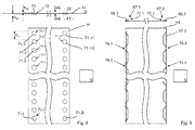
- FIG. 8 shows that the fire protection element 14 has a plurality of rivets 71.1, 71.2, ..., on each of which a projection 72.1, 72.2, ... is formed.
- the rivets 71 in the direction of the rear side 46 have a projection height h 46 .
- This is preferably between 0.5 mm and 7 mm. It is possible, and represents a preferred embodiment, that the projection height h 44 in the direction of the front side 44 corresponds to the projection height h 46. Alternatively, for example, the projection height h 44 in the direction of the front side 44 may be smaller than the projection height h 46 .
- the sum h 46 + h 46 from both projection heights is not more than 8 mm, in particular 7 mm.
- FIG. 9 shows the fire protection element 14 in the embodiment according to FIG. 6 .
- the envelopes 67.1, 67.2 have interruptions 74.1, 74.2,.... These interruptions, which represent a preferred embodiment, cause the fire protection element 14 more easily on a winding shaft 24 (see. FIG. 1 ) can be wound up.
- FIG. 10a shows a guide rail 20 of a fire or smoke protection curtain according to the invention.
- the guide rail 20 has an end face 76.
- the end face 76 is that surface which can be seen when looking parallel to the closing plane S of the fire protection element 14 on the guide rail 20.
- the face 76 can theoretically be divided into area 77.1, 77.2, 77.3 and / or area quartiles 78.1, 78.2, 78.3, 78.4, wherein all area quartiles are the same width and together give the full width of the face 76.
- the first surface area 77.1 and the first area quartile 78.1 are adjacent to the wall 12 to which the guide rail 20 is attached.
- the closing surface S extends in the outermost surface center 77.3 of the end face 76 through the end face 76. In the present case, the closing surface S extends through the end face 76, even in the outermost surface quartile 78.4. In other words, the guide rail 20 according to the invention does not require the installation space which would extend beyond the last surface 77.3 of the prior art guide rails Wall 12 seen from the guide rail is so behind the closing surface or closing plane S significantly thinner than before.
- the second support portion 54 of the guide rail 20 has in this case a first portion 80.1, which extends along the guide surface E 54 , and a second portion 80.2.
- the support edge 40 separates both sections 80.1, 80.2 from each other.
- the second section 80.2 extends at an angle to the guide surface E 54 .
- an angle ⁇ between the guide surface E 54 and the extension direction of the second partial section 80.2 is 15 ° to 45 °, in the present case approximately 30 °.
- the second support section 54 yields particularly little. The projection 72 is therefore held securely on the support edge 38.
- FIG. 10b shows the guide rail 20 according to FIG. 10a , wherein the tensile force Fs was applied to the fire protection element 14. It can be seen that the slot 43 tapers by the tensile force Fs. The tensile force Fs causes only those parts of the guide rail to move in the direction of the tensile force that is in the first half space 39. In the present case, this is the sheet on which the support edge 38 is formed. The sheet with the support portion 54 does not move in the direction of the tensile force but slightly in a direction perpendicular thereto.
- FIG. 10c shows a further embodiment of a guide rail 10 and a fire protection element 14 of a fire or smoke protection curtain 10 according to the invention. It can be seen that the projection 72 is formed in this embodiment on a holding element 70.
- FIG. 10c also shows in detail the forces acting.
- the projection 72 presses on the support edge 38.
- the support edge 38 exerts the support edge force 38 on the projection 72.
- the coupling section 36.14 exerts the coupling section force F 36 on the guide rail 20, in the present case on the second support section 54.
- the feature that the old force is received at least predominantly from the support edge 38 is understood in particular to mean that
- FIG. 11 a shows an embodiment in which the projection as in the FIGS. 6 and 7 is formed on holding elements 70.
- the protrusion height h 46 (see FIG. Fig. 8 , upper partial image) greater than the projection height h 44 . This has the consequence that the holding member 70 abuts with the part on the support edge 38, the projection height is greater.
- FIG. 11b shows the guide rail according to FIG. 11a in another perspective view.
- FIG. 12a shows a further embodiment of a guide rail 20 of a fire or smoke protection curtain according to the invention, which has a piping 82 in the form of a Kederstange.
- the fire protection element 14 extends in its coupling portion 36 around the piping 82 around.
- the holding force F H is applied by the support edge 38.
- the Kederstange 83 holds the lateral edge of the fire protection element 14 in the guide rail 20 and is arranged in the guide rail 14, that the cross-sectional area A of the Kederstange 83 completely on the side of the back 46, here the wall side of the fire protection element 14.
- the cross-sectional area A is also completely on the wall-side side of the closing surface S, which here is a closing plane.
- FIG. 12b shows a further embodiment of the invention, which differs from the otherwise identically constructed embodiment according to FIG. 10c characterized *** in that the keder bar 82 causes the projection 72 to be formed. Although a part of the guide rail 20 extends in the second half space 41, but these components do not absorb the holding force.
- FIG. 12c shows a further embodiment in which a plurality of retaining elements 70 is present, of which only the retaining element 70.1 is located.
- the holding elements have a concave lateral surface which cooperates with the support edges 38, 40 in a form-fitting manner.
Landscapes
- Engineering & Computer Science (AREA)
- Structural Engineering (AREA)
- Architecture (AREA)
- Civil Engineering (AREA)
- Health & Medical Sciences (AREA)
- Electromagnetism (AREA)
- Physics & Mathematics (AREA)
- Public Health (AREA)
- Business, Economics & Management (AREA)
- Emergency Management (AREA)
- Toxicology (AREA)
- Mechanical Engineering (AREA)
- Operating, Guiding And Securing Of Roll- Type Closing Members (AREA)
- Curtains And Furnishings For Windows Or Doors (AREA)
Applications Claiming Priority (1)
| Application Number | Priority Date | Filing Date | Title |
|---|---|---|---|
| DE102015114388.7A DE102015114388A1 (de) | 2015-08-28 | 2015-08-28 | Brand- oder Rauchschutzvorhang |
Publications (1)
| Publication Number | Publication Date |
|---|---|
| EP3135342A1 true EP3135342A1 (fr) | 2017-03-01 |
Family
ID=56787286
Family Applications (1)
| Application Number | Title | Priority Date | Filing Date |
|---|---|---|---|
| EP16184338.8A Withdrawn EP3135342A1 (fr) | 2015-08-28 | 2016-08-16 | Rideau coupe-feu ou pare-fumees |
Country Status (3)
| Country | Link |
|---|---|
| US (1) | US10221561B2 (fr) |
| EP (1) | EP3135342A1 (fr) |
| DE (1) | DE102015114388A1 (fr) |
Cited By (1)
| Publication number | Priority date | Publication date | Assignee | Title |
|---|---|---|---|---|
| CN113421394A (zh) * | 2021-05-31 | 2021-09-21 | 义乌市吉龙科技有限公司 | 一种智能家用燃气全程检测控制系统 |
Families Citing this family (13)
| Publication number | Priority date | Publication date | Assignee | Title |
|---|---|---|---|---|
| ES2561905B1 (es) * | 2014-08-29 | 2016-11-16 | Amiserru, S.L. | Cerramiento modular |
| US11248416B2 (en) * | 2016-01-13 | 2022-02-15 | Cornellcookson, Llc | Roll-up doors and method for securing same |
| US20180156577A1 (en) * | 2016-12-02 | 2018-06-07 | Ballistic Cordon Systems, LLC | Ballistic Curtain Cordon System |
| US10774585B2 (en) | 2017-03-31 | 2020-09-15 | Hunter Douglas Inc | Perimeter light blockout system |
| TWI657188B (zh) * | 2018-02-13 | 2019-04-21 | 寰奇機電有限公司 | 氣密式防火防煙捲門結構 |
| US20240218657A1 (en) * | 2018-04-30 | 2024-07-04 | Cemco, Llc | Firestop flute plug |
| US12048856B2 (en) * | 2020-05-19 | 2024-07-30 | Mckeon Rolling Steel Door Co., Inc. | Multi layer fire curtain |
| GB2599962B (en) * | 2020-10-19 | 2023-09-13 | Amsafe Bridport Ltd | An aircraft compartmental barrier |
| DE102022117412A1 (de) | 2021-08-06 | 2023-02-09 | Hörmann Kg Dissen | Sturmanker-Endstück für Rolltorprofile sowie Verwendungen desselben |
| US12264539B2 (en) * | 2021-12-08 | 2025-04-01 | Cornellcookson, Llc | Guide closing mechanism for fire shutters |
| CN117328720A (zh) * | 2023-02-20 | 2024-01-02 | 呐喊有限公司 | 可变空间泊车库及建筑物 |
| GB202305897D0 (en) * | 2023-04-21 | 2023-06-07 | Burgess Kevin Raymond | A guide and fire curtain assembly |
| DE102023120689A1 (de) * | 2023-08-03 | 2025-02-06 | EFAFLEX INŽENIRING d.o.o. Ljubljana | Hubtor, insbesondere schnelllaufendes hubtor, sowie schiebeführung hierfür |
Citations (8)
| Publication number | Priority date | Publication date | Assignee | Title |
|---|---|---|---|---|
| DE29922593U1 (de) * | 1999-12-23 | 2000-04-13 | Stöbich Brandschutz GmbH & Co. KG, 38644 Goslar | Schutzvorhang-Seitenführung |
| DE102005040758A1 (de) * | 2005-08-26 | 2007-03-01 | Webasto Ag | Rolloanordnung |
| US20090165964A1 (en) * | 2007-04-20 | 2009-07-02 | Charles Harbison | Sealing curtain assembly for door or window openings |
| US20090199978A1 (en) * | 2007-07-24 | 2009-08-13 | Crider Grant W | Combination garage door and roll-up curtain system |
| DE102010027555A1 (de) * | 2010-07-19 | 2012-01-19 | Effertz Tore Gmbh | Vorrichtung zur Abdichtung von Vorhängen |
| US20140190097A1 (en) | 2013-01-08 | 2014-07-10 | Rytec Corporation | Ninety degree wind lock with break-away capability and door panel and door assembly utilizing the same |
| FR3004117A1 (fr) | 2013-04-04 | 2014-10-10 | Gesop | Rideau pare-fumee et/ou pare-flamme. |
| TWM494007U (zh) * | 2014-07-02 | 2015-01-21 | Pei-Cen Ke | 具抗拉隔煙簾裝置 |
Family Cites Families (12)
| Publication number | Priority date | Publication date | Assignee | Title |
|---|---|---|---|---|
| US1882982A (en) * | 1930-11-25 | 1932-10-18 | August J Schmiedeskamp | Rolling screen retaining means |
| US4649981A (en) * | 1985-03-07 | 1987-03-17 | Appropriate Technology Corporation | Edge seal for fabric covers |
| US5570544A (en) * | 1994-11-10 | 1996-11-05 | Hale; Gary A. | Inflatable structure |
| US6068040A (en) * | 1998-07-24 | 2000-05-30 | Alpine Overhead Doors, Inc. | Slat edge retainer for overhead rolling doors |
| US6176039B1 (en) * | 1999-11-22 | 2001-01-23 | Terry A. Craig | Garage door mounted object sensor system |
| US6374543B1 (en) * | 2000-06-06 | 2002-04-23 | Magdy N. Bishai | Door opener apparatus with power transfer mechanism |
| US7128125B2 (en) * | 2004-03-09 | 2006-10-31 | Charles Harbison | Durable sealing curtain |
| US7413000B2 (en) * | 2005-09-14 | 2008-08-19 | Macauto Industrial Co., Ltd. | Sun screen device |
| US8851147B2 (en) * | 2011-03-23 | 2014-10-07 | Rytec Corporation | Segmented wind lock configuration for overhead roll-up doors and method of constructing the same |
| US9187953B2 (en) * | 2011-03-23 | 2015-11-17 | Rytec Corporation | Side column configuration for overhead roll-up door assemblies |
| US8887790B2 (en) * | 2011-09-13 | 2014-11-18 | Rytec Corporation | Wind lock configuration for overhead roll-up doors |
| US9493984B2 (en) * | 2013-04-12 | 2016-11-15 | Rite-Hite Holding Corporation | Systems and methods to retain and refeed door curtains |
-
2015
- 2015-08-28 DE DE102015114388.7A patent/DE102015114388A1/de not_active Withdrawn
-
2016
- 2016-08-16 EP EP16184338.8A patent/EP3135342A1/fr not_active Withdrawn
- 2016-08-24 US US15/245,698 patent/US10221561B2/en not_active Expired - Fee Related
Patent Citations (8)
| Publication number | Priority date | Publication date | Assignee | Title |
|---|---|---|---|---|
| DE29922593U1 (de) * | 1999-12-23 | 2000-04-13 | Stöbich Brandschutz GmbH & Co. KG, 38644 Goslar | Schutzvorhang-Seitenführung |
| DE102005040758A1 (de) * | 2005-08-26 | 2007-03-01 | Webasto Ag | Rolloanordnung |
| US20090165964A1 (en) * | 2007-04-20 | 2009-07-02 | Charles Harbison | Sealing curtain assembly for door or window openings |
| US20090199978A1 (en) * | 2007-07-24 | 2009-08-13 | Crider Grant W | Combination garage door and roll-up curtain system |
| DE102010027555A1 (de) * | 2010-07-19 | 2012-01-19 | Effertz Tore Gmbh | Vorrichtung zur Abdichtung von Vorhängen |
| US20140190097A1 (en) | 2013-01-08 | 2014-07-10 | Rytec Corporation | Ninety degree wind lock with break-away capability and door panel and door assembly utilizing the same |
| FR3004117A1 (fr) | 2013-04-04 | 2014-10-10 | Gesop | Rideau pare-fumee et/ou pare-flamme. |
| TWM494007U (zh) * | 2014-07-02 | 2015-01-21 | Pei-Cen Ke | 具抗拉隔煙簾裝置 |
Cited By (1)
| Publication number | Priority date | Publication date | Assignee | Title |
|---|---|---|---|---|
| CN113421394A (zh) * | 2021-05-31 | 2021-09-21 | 义乌市吉龙科技有限公司 | 一种智能家用燃气全程检测控制系统 |
Also Published As
| Publication number | Publication date |
|---|---|
| US20170058513A1 (en) | 2017-03-02 |
| DE102015114388A1 (de) | 2017-03-02 |
| US10221561B2 (en) | 2019-03-05 |
Similar Documents
| Publication | Publication Date | Title |
|---|---|---|
| DE102015114388A1 (de) | Brand- oder Rauchschutzvorhang | |
| EP2508232B1 (fr) | Dispositif coupe-feu ou pare-fumées et bâtiment en étant équipé | |
| AT16721U1 (de) | Träger für eine lineare deckenplatte | |
| DE102010027555A1 (de) | Vorrichtung zur Abdichtung von Vorhängen | |
| WO2011124377A1 (fr) | Dispositif coupe-feu ou coupe-fumée | |
| EP2939712B1 (fr) | Rideau pare-feu | |
| DE102012003591A1 (de) | Führungsschiene für eine Senkrechtmarkise und Senkrechtmarkise | |
| EP3705676B1 (fr) | Procédé de montage d'un coffre de volet roulant et coffre de volet roulant posé sur une partie du cadre | |
| DE202016101593U1 (de) | Vorrichtung gegen das Eindringen von Flüssigkeiten | |
| EP1669110A2 (fr) | Dispositif d'étanchéité pour un rideau coupe-feu ou coupe-fumée | |
| EP2876243B1 (fr) | Portail coulissant avec porte battante intégrée | |
| DE102014003033A1 (de) | Brandschutzvorrichtung für eine Wand oder Decke zum Einsetzen in eine Lüftungsleitung | |
| EP3889384A1 (fr) | Profilé extrudé de section creuse de fenêtre ou de porte, système doté d'un tel profilé de section creuse et cadre fabriqué à partir de celui-ci | |
| DE4011605C2 (de) | Bauelement, insbesondere Wand- oder Türelement | |
| DE102019103530A1 (de) | Brand- oder Rauchschutzvorhang | |
| DE202010009538U1 (de) | Feuerhemmendes Rollo | |
| DE102013015352B4 (de) | Blendenprofil zur Anbringung einer Abschlussblende an einem Ojekt, zum Beispiel einem Möbelstück und System, umfassend ein Blendenprofil, ein Objekt und eine Abschlussblende | |
| DE102014006227A1 (de) | Brandschutzvorhang | |
| EP3894730B1 (fr) | Segment de manchon ignifuge et manchon ignifuge | |
| DE102010020989A1 (de) | Einbruchhemmende Wand | |
| DE102011012657B3 (de) | Brand- oder Rauchschutzvorhang zum Verschließen einer Gebäudeöffnung und dazugehöriges Verfahren | |
| EP2578790B1 (fr) | Vantail d'une porte coupe-feu | |
| EP3006091B1 (fr) | Dispositif coupe-feu ou pare-fumees | |
| EP4209640A1 (fr) | Profilé coupe-feu, élément de cellule de régulation de température de pièce doté de tels profilés coupe-feu et leur utilisation | |
| EP3894022A1 (fr) | Élément ignifuge comprenant un bimétal |
Legal Events
| Date | Code | Title | Description |
|---|---|---|---|
| PUAI | Public reference made under article 153(3) epc to a published international application that has entered the european phase |
Free format text: ORIGINAL CODE: 0009012 |
|
| STAA | Information on the status of an ep patent application or granted ep patent |
Free format text: STATUS: THE APPLICATION HAS BEEN PUBLISHED |
|
| AK | Designated contracting states |
Kind code of ref document: A1 Designated state(s): AL AT BE BG CH CY CZ DE DK EE ES FI FR GB GR HR HU IE IS IT LI LT LU LV MC MK MT NL NO PL PT RO RS SE SI SK SM TR |
|
| AX | Request for extension of the european patent |
Extension state: BA ME |
|
| STAA | Information on the status of an ep patent application or granted ep patent |
Free format text: STATUS: REQUEST FOR EXAMINATION WAS MADE |
|
| 17P | Request for examination filed |
Effective date: 20170829 |
|
| RBV | Designated contracting states (corrected) |
Designated state(s): AL AT BE BG CH CY CZ DE DK EE ES FI FR GB GR HR HU IE IS IT LI LT LU LV MC MK MT NL NO PL PT RO RS SE SI SK SM TR |
|
| STAA | Information on the status of an ep patent application or granted ep patent |
Free format text: STATUS: EXAMINATION IS IN PROGRESS |
|
| 17Q | First examination report despatched |
Effective date: 20190821 |
|
| STAA | Information on the status of an ep patent application or granted ep patent |
Free format text: STATUS: THE APPLICATION IS DEEMED TO BE WITHDRAWN |
|
| 18D | Application deemed to be withdrawn |
Effective date: 20220301 |