EP3135573B1 - Roue pour véhicules à califourchon et véhicule à califourchon - Google Patents
Roue pour véhicules à califourchon et véhicule à califourchon Download PDFInfo
- Publication number
- EP3135573B1 EP3135573B1 EP16178907.8A EP16178907A EP3135573B1 EP 3135573 B1 EP3135573 B1 EP 3135573B1 EP 16178907 A EP16178907 A EP 16178907A EP 3135573 B1 EP3135573 B1 EP 3135573B1
- Authority
- EP
- European Patent Office
- Prior art keywords
- connecting portions
- wheel
- hub
- rotation axis
- axis line
- Prior art date
- Legal status (The legal status is an assumption and is not a legal conclusion. Google has not performed a legal analysis and makes no representation as to the accuracy of the status listed.)
- Active
Links
Images


Classifications
-
- B—PERFORMING OPERATIONS; TRANSPORTING
- B62—LAND VEHICLES FOR TRAVELLING OTHERWISE THAN ON RAILS
- B62K—CYCLES; CYCLE FRAMES; CYCLE STEERING DEVICES; RIDER-OPERATED TERMINAL CONTROLS SPECIALLY ADAPTED FOR CYCLES; CYCLE AXLE SUSPENSIONS; CYCLE SIDECARS, FORECARS, OR THE LIKE
- B62K11/00—Motorcycles, engine-assisted cycles or motor scooters with one or two wheels
- B62K11/02—Frames
- B62K11/04—Frames characterised by the engine being between front and rear wheels
-
- B—PERFORMING OPERATIONS; TRANSPORTING
- B60—VEHICLES IN GENERAL
- B60T—VEHICLE BRAKE CONTROL SYSTEMS OR PARTS THEREOF; BRAKE CONTROL SYSTEMS OR PARTS THEREOF, IN GENERAL; ARRANGEMENT OF BRAKING ELEMENTS ON VEHICLES IN GENERAL; PORTABLE DEVICES FOR PREVENTING UNWANTED MOVEMENT OF VEHICLES; VEHICLE MODIFICATIONS TO FACILITATE COOLING OF BRAKES
- B60T1/00—Arrangements of braking elements, i.e. of those parts where braking effect occurs specially for vehicles
- B60T1/02—Arrangements of braking elements, i.e. of those parts where braking effect occurs specially for vehicles acting by retarding wheels
- B60T1/06—Arrangements of braking elements, i.e. of those parts where braking effect occurs specially for vehicles acting by retarding wheels acting otherwise than on tread, e.g. employing rim, drum, disc, or transmission or on double wheels
- B60T1/065—Arrangements of braking elements, i.e. of those parts where braking effect occurs specially for vehicles acting by retarding wheels acting otherwise than on tread, e.g. employing rim, drum, disc, or transmission or on double wheels employing disc
-
- B—PERFORMING OPERATIONS; TRANSPORTING
- B60—VEHICLES IN GENERAL
- B60T—VEHICLE BRAKE CONTROL SYSTEMS OR PARTS THEREOF; BRAKE CONTROL SYSTEMS OR PARTS THEREOF, IN GENERAL; ARRANGEMENT OF BRAKING ELEMENTS ON VEHICLES IN GENERAL; PORTABLE DEVICES FOR PREVENTING UNWANTED MOVEMENT OF VEHICLES; VEHICLE MODIFICATIONS TO FACILITATE COOLING OF BRAKES
- B60T13/00—Transmitting braking action from initiating means to ultimate brake actuator with power assistance or drive; Brake systems incorporating such transmitting means, e.g. air-pressure brake systems
- B60T13/10—Transmitting braking action from initiating means to ultimate brake actuator with power assistance or drive; Brake systems incorporating such transmitting means, e.g. air-pressure brake systems with fluid assistance, drive, or release
- B60T13/58—Combined or convertible systems
- B60T13/588—Combined or convertible systems both fluid and mechanical assistance or drive
-
- B—PERFORMING OPERATIONS; TRANSPORTING
- B60—VEHICLES IN GENERAL
- B60T—VEHICLE BRAKE CONTROL SYSTEMS OR PARTS THEREOF; BRAKE CONTROL SYSTEMS OR PARTS THEREOF, IN GENERAL; ARRANGEMENT OF BRAKING ELEMENTS ON VEHICLES IN GENERAL; PORTABLE DEVICES FOR PREVENTING UNWANTED MOVEMENT OF VEHICLES; VEHICLE MODIFICATIONS TO FACILITATE COOLING OF BRAKES
- B60T13/00—Transmitting braking action from initiating means to ultimate brake actuator with power assistance or drive; Brake systems incorporating such transmitting means, e.g. air-pressure brake systems
- B60T13/74—Transmitting braking action from initiating means to ultimate brake actuator with power assistance or drive; Brake systems incorporating such transmitting means, e.g. air-pressure brake systems with electrical assistance or drive
- B60T13/741—Transmitting braking action from initiating means to ultimate brake actuator with power assistance or drive; Brake systems incorporating such transmitting means, e.g. air-pressure brake systems with electrical assistance or drive acting on an ultimate actuator
-
- B—PERFORMING OPERATIONS; TRANSPORTING
- B60—VEHICLES IN GENERAL
- B60T—VEHICLE BRAKE CONTROL SYSTEMS OR PARTS THEREOF; BRAKE CONTROL SYSTEMS OR PARTS THEREOF, IN GENERAL; ARRANGEMENT OF BRAKING ELEMENTS ON VEHICLES IN GENERAL; PORTABLE DEVICES FOR PREVENTING UNWANTED MOVEMENT OF VEHICLES; VEHICLE MODIFICATIONS TO FACILITATE COOLING OF BRAKES
- B60T17/00—Component parts, details, or accessories of power brake systems not covered by groups B60T8/00, B60T13/00 or B60T15/00, or presenting other characteristic features
- B60T17/18—Safety devices; Monitoring
- B60T17/22—Devices for monitoring or checking brake systems; Signal devices
-
- B—PERFORMING OPERATIONS; TRANSPORTING
- B62—LAND VEHICLES FOR TRAVELLING OTHERWISE THAN ON RAILS
- B62M—RIDER PROPULSION OF WHEELED VEHICLES OR SLEDGES; POWERED PROPULSION OF SLEDGES OR SINGLE-TRACK CYCLES; TRANSMISSIONS SPECIALLY ADAPTED FOR SUCH VEHICLES
- B62M7/00—Motorcycles characterised by position of motor or engine
- B62M7/02—Motorcycles characterised by position of motor or engine with engine between front and rear wheels
- B62M7/04—Motorcycles characterised by position of motor or engine with engine between front and rear wheels below the frame
-
- F—MECHANICAL ENGINEERING; LIGHTING; HEATING; WEAPONS; BLASTING
- F16—ENGINEERING ELEMENTS AND UNITS; GENERAL MEASURES FOR PRODUCING AND MAINTAINING EFFECTIVE FUNCTIONING OF MACHINES OR INSTALLATIONS; THERMAL INSULATION IN GENERAL
- F16D—COUPLINGS FOR TRANSMITTING ROTATION; CLUTCHES; BRAKES
- F16D55/00—Brakes with substantially-radial braking surfaces pressed together in axial direction, e.g. disc brakes
- F16D55/02—Brakes with substantially-radial braking surfaces pressed together in axial direction, e.g. disc brakes with axially-movable discs or pads pressed against axially-located rotating members
- F16D55/22—Brakes with substantially-radial braking surfaces pressed together in axial direction, e.g. disc brakes with axially-movable discs or pads pressed against axially-located rotating members by clamping an axially-located rotating disc between movable braking members, e.g. movable brake discs or brake pads
- F16D55/224—Brakes with substantially-radial braking surfaces pressed together in axial direction, e.g. disc brakes with axially-movable discs or pads pressed against axially-located rotating members by clamping an axially-located rotating disc between movable braking members, e.g. movable brake discs or brake pads with a common actuating member for the braking members
- F16D55/225—Brakes with substantially-radial braking surfaces pressed together in axial direction, e.g. disc brakes with axially-movable discs or pads pressed against axially-located rotating members by clamping an axially-located rotating disc between movable braking members, e.g. movable brake discs or brake pads with a common actuating member for the braking members the braking members being brake pads
- F16D55/226—Brakes with substantially-radial braking surfaces pressed together in axial direction, e.g. disc brakes with axially-movable discs or pads pressed against axially-located rotating members by clamping an axially-located rotating disc between movable braking members, e.g. movable brake discs or brake pads with a common actuating member for the braking members the braking members being brake pads in which the common actuating member is moved axially, e.g. floating caliper disc brakes
-
- F—MECHANICAL ENGINEERING; LIGHTING; HEATING; WEAPONS; BLASTING
- F16—ENGINEERING ELEMENTS AND UNITS; GENERAL MEASURES FOR PRODUCING AND MAINTAINING EFFECTIVE FUNCTIONING OF MACHINES OR INSTALLATIONS; THERMAL INSULATION IN GENERAL
- F16D—COUPLINGS FOR TRANSMITTING ROTATION; CLUTCHES; BRAKES
- F16D65/00—Parts or details
- F16D65/14—Actuating mechanisms for brakes; Means for initiating operation at a predetermined position
- F16D65/16—Actuating mechanisms for brakes; Means for initiating operation at a predetermined position arranged in or on the brake
- F16D65/18—Actuating mechanisms for brakes; Means for initiating operation at a predetermined position arranged in or on the brake adapted for drawing members together, e.g. for disc brakes
- F16D65/183—Actuating mechanisms for brakes; Means for initiating operation at a predetermined position arranged in or on the brake adapted for drawing members together, e.g. for disc brakes with force-transmitting members arranged side by side acting on a spot type force-applying member
-
- F—MECHANICAL ENGINEERING; LIGHTING; HEATING; WEAPONS; BLASTING
- F16—ENGINEERING ELEMENTS AND UNITS; GENERAL MEASURES FOR PRODUCING AND MAINTAINING EFFECTIVE FUNCTIONING OF MACHINES OR INSTALLATIONS; THERMAL INSULATION IN GENERAL
- F16D—COUPLINGS FOR TRANSMITTING ROTATION; CLUTCHES; BRAKES
- F16D66/00—Arrangements for monitoring working conditions, e.g. wear, temperature
-
- B—PERFORMING OPERATIONS; TRANSPORTING
- B60—VEHICLES IN GENERAL
- B60B—VEHICLE WHEELS; CASTORS; AXLES FOR WHEELS OR CASTORS; INCREASING WHEEL ADHESION
- B60B1/00—Spoked wheels; Spokes thereof
- B60B1/06—Wheels with compression spokes
- B60B1/08—Wheels with compression spokes formed by casting
-
- B—PERFORMING OPERATIONS; TRANSPORTING
- B60—VEHICLES IN GENERAL
- B60B—VEHICLE WHEELS; CASTORS; AXLES FOR WHEELS OR CASTORS; INCREASING WHEEL ADHESION
- B60B2310/00—Manufacturing methods
- B60B2310/20—Shaping
- B60B2310/202—Shaping by casting
-
- B—PERFORMING OPERATIONS; TRANSPORTING
- B60—VEHICLES IN GENERAL
- B60Y—INDEXING SCHEME RELATING TO ASPECTS CROSS-CUTTING VEHICLE TECHNOLOGY
- B60Y2200/00—Type of vehicle
- B60Y2200/10—Road Vehicles
- B60Y2200/12—Motorcycles, Trikes; Quads; Scooters
-
- F—MECHANICAL ENGINEERING; LIGHTING; HEATING; WEAPONS; BLASTING
- F16—ENGINEERING ELEMENTS AND UNITS; GENERAL MEASURES FOR PRODUCING AND MAINTAINING EFFECTIVE FUNCTIONING OF MACHINES OR INSTALLATIONS; THERMAL INSULATION IN GENERAL
- F16D—COUPLINGS FOR TRANSMITTING ROTATION; CLUTCHES; BRAKES
- F16D66/00—Arrangements for monitoring working conditions, e.g. wear, temperature
- F16D2066/005—Force, torque, stress or strain
-
- F—MECHANICAL ENGINEERING; LIGHTING; HEATING; WEAPONS; BLASTING
- F16—ENGINEERING ELEMENTS AND UNITS; GENERAL MEASURES FOR PRODUCING AND MAINTAINING EFFECTIVE FUNCTIONING OF MACHINES OR INSTALLATIONS; THERMAL INSULATION IN GENERAL
- F16D—COUPLINGS FOR TRANSMITTING ROTATION; CLUTCHES; BRAKES
- F16D2121/00—Type of actuator operation force
- F16D2121/02—Fluid pressure
-
- F—MECHANICAL ENGINEERING; LIGHTING; HEATING; WEAPONS; BLASTING
- F16—ENGINEERING ELEMENTS AND UNITS; GENERAL MEASURES FOR PRODUCING AND MAINTAINING EFFECTIVE FUNCTIONING OF MACHINES OR INSTALLATIONS; THERMAL INSULATION IN GENERAL
- F16D—COUPLINGS FOR TRANSMITTING ROTATION; CLUTCHES; BRAKES
- F16D2121/00—Type of actuator operation force
- F16D2121/18—Electric or magnetic
- F16D2121/24—Electric or magnetic using motors
Definitions
- One of the objects of the present invention is to realize weight reduction and low cost in a wheel for straddled vehicles which is manufactured using die casting.
- the invention provides a wheel according to claim 1.
- each of the first connecting portions and the second connecting portions has a stick-like shape
- the projected areas in the rotation axis line direction of a through hole between a first connecting portion and a second connecting portion adjoining each other can easily be increased. Therefore, weight reduction of the wheel for straddled vehicles and reduction of the manufacturing cost can be realized more easily.
- a length defined along a radial direction of each of the plurality of second connecting portions is greater than a length defined along a longitudinal direction in a cross section which is perpendicular to a radial direction.
- a first connecting portion is generally equally distant from two second connecting portions, and a second connecting portion is generally equally distant from two first connecting portions. In such a case, manufacture and designing are easy.
- a disk brake When a disk brake is used as the brake, for example, holes are provided in the outer perimeter portion of the hub for securing the brake disk.
- the through holes are provided between the first connecting portions and the second connecting portions as in the embodiment of the present invention, the hub can be easily cleaned even if the brake disk is kept secured to the wheel.
- a straddled vehicle according to another embodiment of the present invention includes a wheel which has any of the above-described configurations.
- a wheel for straddled vehicles according to an embodiment of the present invention is suitably used in various straddled vehicles because weight reduction and reduction of the manufacturing cost can be realized.
- cleaning of the hub is easy.
- using a wheel for straddled vehicles according to the embodiment of the present invention enables to improve maintenance easiness of the straddled vehicles.
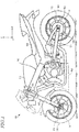
- a swing arm 121 is swingably supported.
- a driven sprocket 122 and a rear wheel unit 123 are rotatably supported.
- the rear wheel unit 123 includes a wheel 10. This wheel 10 is rotatably attached to the rear end of the swing arm 121.
- the wheel 10 includes a brake disk 110.
- a chain 124 is looped between a drive sprocket 120 and the driven sprocket 122.
- a driving power produced by the engine 117 is transferred to the rear wheel unit 123 via the chain 124.
- the wheel 10 includes, as shown in FIG. 2 , an annular rim 12, a hub 20 through which an axle is to be inserted, and a plurality of spokes 14 connecting the rim 12 and the hub 20.
- a tire is fit on the rim 12 (see FIG. 1 ) .
- the number of spokes 14 is not limited to the example shown in FIG. 2 (10 spokes). Also, the shape and arrangement of the spokes 14 are not limited to the example shown in FIG. 2 .
- the inner perimeter portion 22 and the outer perimeter portion 24 each have the shape of a cylinder extending in the rotation axis line direction.
- the inner perimeter portion 22 has the shape of a generally circular cylinder
- the outer perimeter portion 24 has the shape of a generally polygonal cylinder (more specifically, a generally pentagonal cylinder).
- the shape of the inner perimeter portion 22 and the shape of the outer perimeter portion 24 are not limited to those illustrated herein.
- the outer perimeter portion 24 may have the shape of a generally circular cylinder.
- the outer perimeter portion 24 has a plurality of holes 28 which are used for securing the brake disk 110 (see FIG. 1 ). For example, bolts are screwed into these holes 28.
- Each of the first connecting portions 26L and the second connecting portions 26R of the present embodiment has a stick-like shape.
- the cross-sectional shape of each of the first connecting portions 26L and the second connecting portions 26R is arbitrary. For example, it can be polygonal, circular, or elliptical.
- length L1' defined along the first direction that is the longitudinal direction, length L2' defined along the second direction that is perpendicular to the first direction, and length L3' defined along the radial direction of the second connecting portion 26R are considered (see FIG. 4 ).
- lengths L1', L2' and L3' are also referred to as "first length”, “second length” and “third length”, respectively, for the sake of convenience.
- the ratio between first length L1 and second length L2 of the first connecting portion 26L and the ratio between first length L1' and second length L2' of the second connecting portion 26R are each preferably within a predetermined range. Specifically, when the ratio between first length L1 and second length L2 of the first connecting portion 26L is from 1:1 to 1.5:1, the strength of the hub can be sufficiently secured, and the projected area of the through holes 32 in the rotation axis line direction can be sufficiently large. Likewise, when the ratio between first length L1' and second length L2' of the second connecting portion 26R is from 1:1 to 1.5:1, the strength of the hub can be sufficiently secured, and the projected area of the through holes 32 in the rotation axis line direction can be sufficiently large.
- the hub 20 has five first connecting portions 26L and five second connecting portions 26R
- the number of the plurality of first connecting portions 26L and the number of the plurality of second connecting portions 26R are arbitrary and are not particularly limited. From the viewpoints of weight reduction and improvement in maintenance easiness, the number of the plurality of first connecting portions and the number of the plurality of second connecting portions are preferably smaller. Specifically, it is preferred that the number of the plurality of first connecting portions and the number of the plurality of second connecting portions are each not more than five. Note that, however, from the viewpoint of securing sufficiently high hub strength, it is preferred that the number of the plurality of first connecting portions and the number of the plurality of second connecting portions are each not less than three.
- FIG. 6 and FIG. 7 show a mold 40 for use in die casting that is for manufacture of the wheel 10.
- FIG. 6 and FIG. 7 respectively show a cross-sectional structure of the opened mold 40 and a cross-sectional structure of the closed mold 40, each showing a region that forms a portion of the hub 20 taken along line B-B of FIG. 3 .
- the first connecting portions 26L of the example illustrated in FIG. 9 are located at positions shifted clockwise relative to the first connecting portions 26L of the example illustrated in FIG. 3 .
- the first connecting portions 26L are located at positions shifted clockwise by 3/4 of the pitch relative to the second connecting portions 26R.
Landscapes
- Engineering & Computer Science (AREA)
- Mechanical Engineering (AREA)
- General Engineering & Computer Science (AREA)
- Transportation (AREA)
- Chemical & Material Sciences (AREA)
- Combustion & Propulsion (AREA)
- Molds, Cores, And Manufacturing Methods Thereof (AREA)
Claims (10)
- Roue (10) pour véhicules à selle (100) qui est un produit moulé sous pression, comprenant:une jante annulaire (12);un moyeu (20) à travers lequel doit être inséré un essieu; etune pluralité de rayons (14) connectant la jante (12) et le moyeu (20),dans lequel le moyeu (20) présente une pluralité de parties de connexion (26, 26L, 26R) connectant une partie de périmètre intérieur (22) et une partie de périmètre extérieur (24) du moyeu (20), la pluralité de parties de connexion (26, 26L, 26R) étant disposées de manière à s'étendre radialement de la partie de périmètre intérieur (22) à la partie de périmètre extérieur (24) et à être espacées l'une de l'autre dans une direction circonférentielle,la pluralité de parties de connexion (26, 26L, 26R) comportent une pluralité de premières parties de connexion (26L) situées d'un côté de la roue dans une direction de la ligne d'axe de rotation dans laquelle s'étend une ligne d'axe de rotation (18) de la roue pour véhicules à selle (100) et une pluralité de deuxièmes parties de connexion (26R) situées de l'autre côté de la roue,lorsque le moyeu (20) est vu dans la direction de la ligne d'axe de rotation, chacune de la pluralité de premières parties de connexion (26L) est présente entre deux de la pluralité de deuxièmes parties de connexion (26R) adjacentes l'une à l'autre dans la direction circonférentielle, et chacune de la pluralité de deuxièmes parties de connexion (26R) est présente entre deux de la pluralité de premières parties de connexion (26L) adjacentes l'une à l'autre dans la direction circonférentielle, etcaractérisée par le fait que, lorsque le moyeu (20) est vu dans la direction de la ligne d'axe de rotation, le moyeu comporte des trous traversants (32) pénétrant dans la direction de la ligne d'axe de rotation, de sorte qu'il existe un trou traversant entre chaque première partie de connexion (26L) et chaque deuxième partie de connexion (26R) adjacente à la première partie de connexion dans la direction circonférentielle.
- Roue (10) pour véhicules à selle (100) selon la revendication 1, dans laquelle chacune de la pluralité de premières parties de connexion (26L) et chacune de la pluralité de deuxièmes parties de connexion (26R) présente une forme de type bâton.
- Roue (10) pour véhicules à selle (100) selon la revendication 2, dans laquelle, dans une section transversale de chacune de la pluralité de premières parties de connexion (26L) et chacune de la pluralité de deuxièmes parties de connexion (26R) qui est perpendiculaire à une direction radiale, le rapport entre une longueur définie dans une première direction qui est une direction longitudinale et une longueur définie dans une deuxième direction qui est perpendiculaire à la première direction est de 1:1 à 1,5:1.
- Roue (10) pour véhicules à selle (100) selon la revendication 2 ou 3, dans laquelle une longueur définie dans une direction radiale de chacune de la pluralité de premières parties de connexion (26L) est supérieure à une longueur définie dans une direction longitudinale dans une section transversale qui est perpendiculaire à une direction radiale.
- Roue (10) pour véhicules à selle (100) selon l'une quelconque des revendications 2 à 4, dans laquelle une longueur définie dans une direction radiale de chacune de la pluralité de deuxièmes parties de connexion (26R) est supérieure à une longueur définie dans une direction longitudinale dans une section perpendiculaire à une direction radiale.
- Roue (10) pour véhicules à selle (100) selon l'une quelconque des revendications 1 à 5, dans laquellechacune de la pluralité de premières parties de connexion (26L) est généralement équidistante des deux deuxièmes parties de connexion (26R) lorsque le moyeu (20) est vu dans la direction de la ligne d'axe de rotation, etchacune de la pluralité de deuxièmes parties de connexion (26R) est généralement équidistante des deux premières parties de connexion (26L) lorsque le moyeu (20) est vu dans la direction de la ligne d'axe de rotation.
- Roue (10) pour véhicules à selle (100) selon l'une quelconque des revendications 1 à 6, dans laquelle un nombre de la pluralité de premières parties de connexion (26L) n'est pas inférieur à trois et pas supérieur à cinq, et un nombre de la pluralité de deuxièmes parties de connexion (26R) n'est pas inférieur à trois et pas supérieur à cinq.
- Roue (10) pour véhicules à selle (100) selon l'une quelconque des revendications 1 à 7, dans laquelle la roue (10) pour véhicules à selle (100) est une roue (10) qui est réalisée en alliage d'aluminium.
- Roue (10) pour véhicules à selle (100) selon l'une quelconque des revendications 1 à 8, dans laquelle la partie de périmètre extérieur (24) du moyeu (20) présente un trou (28) utilisé pour fixer un disque de frein (110) .
- Véhicule à selle (100) comprenant la roue (10) selon l'une quelconque des revendications 1 à 9.
Applications Claiming Priority (2)
| Application Number | Priority Date | Filing Date | Title |
|---|---|---|---|
| JP2015143104 | 2015-07-17 | ||
| JP2016104834A JP2017024705A (ja) | 2015-07-17 | 2016-05-26 | 鞍乗型車両用ホイールおよび鞍乗型車両 |
Publications (3)
| Publication Number | Publication Date |
|---|---|
| EP3135573A2 EP3135573A2 (fr) | 2017-03-01 |
| EP3135573A3 EP3135573A3 (fr) | 2017-03-29 |
| EP3135573B1 true EP3135573B1 (fr) | 2018-07-04 |
Family
ID=56550026
Family Applications (1)
| Application Number | Title | Priority Date | Filing Date |
|---|---|---|---|
| EP16178907.8A Active EP3135573B1 (fr) | 2015-07-17 | 2016-07-11 | Roue pour véhicules à califourchon et véhicule à califourchon |
Country Status (1)
| Country | Link |
|---|---|
| EP (1) | EP3135573B1 (fr) |
Cited By (1)
| Publication number | Priority date | Publication date | Assignee | Title |
|---|---|---|---|---|
| WO2025093353A1 (fr) * | 2023-10-31 | 2025-05-08 | Bayerische Motoren Werke Aktiengesellschaft | Jante et motocyclette |
Families Citing this family (1)
| Publication number | Priority date | Publication date | Assignee | Title |
|---|---|---|---|---|
| JP2020175792A (ja) * | 2019-04-19 | 2020-10-29 | ヤマハ発動機株式会社 | ダイカストホイールおよび鞍乗型車両 |
Family Cites Families (6)
| Publication number | Priority date | Publication date | Assignee | Title |
|---|---|---|---|---|
| JPS5812801A (ja) * | 1981-07-17 | 1983-01-25 | Yamaha Motor Co Ltd | 自動二輪車用ホイ−ル |
| DE4013603A1 (de) * | 1989-05-03 | 1991-02-07 | Ulrich Dipl Ing Wahl | Motorradgussrad |
| JP3232380B2 (ja) | 1992-12-18 | 2001-11-26 | ヤマハ発動機株式会社 | 自動二輪車用ダイカスト製ホイール |
| DE19601778C2 (de) * | 1995-10-11 | 1998-09-10 | Porsche Ag | Rad für ein Kraftfahrzeug |
| JPH1029402A (ja) * | 1996-07-16 | 1998-02-03 | Honda Motor Co Ltd | 車両用ホイール |
| JP3836392B2 (ja) * | 2002-04-26 | 2006-10-25 | 本田技研工業株式会社 | 自動二輪車用ホイール |
-
2016
- 2016-07-11 EP EP16178907.8A patent/EP3135573B1/fr active Active
Non-Patent Citations (1)
| Title |
|---|
| None * |
Cited By (1)
| Publication number | Priority date | Publication date | Assignee | Title |
|---|---|---|---|---|
| WO2025093353A1 (fr) * | 2023-10-31 | 2025-05-08 | Bayerische Motoren Werke Aktiengesellschaft | Jante et motocyclette |
Also Published As
| Publication number | Publication date |
|---|---|
| EP3135573A3 (fr) | 2017-03-29 |
| EP3135573A2 (fr) | 2017-03-01 |
Similar Documents
| Publication | Publication Date | Title |
|---|---|---|
| US20100239363A1 (en) | Connecting flange for transmission elements of cycles and motorcycles | |
| CN105270561B (zh) | 无链自行车及其轮叉、车架 | |
| EP3135573A2 (fr) | Roue pour véhicules à califourchon et véhicule à califourchon | |
| KR20190015471A (ko) | 고안정성을 가지는 일체로 사출 성형된 임펠러 | |
| US9511622B2 (en) | Wheel of vehicle | |
| CN105346668B (zh) | 无链自行车及其后轴组件 | |
| EP1780048B1 (fr) | Roue pour motocycle et son procédé de fabrication | |
| US8550201B2 (en) | Swing arm for miniaturized vehicle | |
| EP2626217B1 (fr) | Roue pour motocyclette | |
| JP6043029B2 (ja) | 自動二輪車用のアルミホイール | |
| JP4119334B2 (ja) | バランスウエイトおよびスポークホイールのバランス補正構造 | |
| EP3222439B1 (fr) | Roue coulée et véhicule de type à selle | |
| JP2017024705A (ja) | 鞍乗型車両用ホイールおよび鞍乗型車両 | |
| JP6043336B2 (ja) | ホイール及び自動二輪車 | |
| JP6411879B2 (ja) | 鞍乗型車両 | |
| CN110015372B (zh) | 框架结构 | |
| JP6352590B2 (ja) | 鞍乗り型車両のホイール及びその周辺構造 | |
| CN105346669B (zh) | 无链自行车及其轮组 | |
| JP2017065336A (ja) | スイングアーム | |
| DE102020203338B4 (de) | Gussrad | |
| JP2013136306A (ja) | 鞍乗型車両 | |
| WO2015182247A1 (fr) | Structure pour roue de véhicule à selle | |
| EP3725540B1 (fr) | Roue coulée sous pression, unité de roue et véhicule à enfourcher | |
| TWI676571B (zh) | 跨坐型車輛及其組裝方法 | |
| EP3533621A1 (fr) | Structure d'amortisseur de roue |
Legal Events
| Date | Code | Title | Description |
|---|---|---|---|
| PUAI | Public reference made under article 153(3) epc to a published international application that has entered the european phase |
Free format text: ORIGINAL CODE: 0009012 |
|
| STAA | Information on the status of an ep patent application or granted ep patent |
Free format text: STATUS: THE APPLICATION HAS BEEN PUBLISHED |
|
| PUAL | Search report despatched |
Free format text: ORIGINAL CODE: 0009013 |
|
| AK | Designated contracting states |
Kind code of ref document: A2 Designated state(s): AL AT BE BG CH CY CZ DE DK EE ES FI FR GB GR HR HU IE IS IT LI LT LU LV MC MK MT NL NO PL PT RO RS SE SI SK SM TR |
|
| AX | Request for extension of the european patent |
Extension state: BA ME |
|
| AK | Designated contracting states |
Kind code of ref document: A3 Designated state(s): AL AT BE BG CH CY CZ DE DK EE ES FI FR GB GR HR HU IE IS IT LI LT LU LV MC MK MT NL NO PL PT RO RS SE SI SK SM TR |
|
| AX | Request for extension of the european patent |
Extension state: BA ME |
|
| RIC1 | Information provided on ipc code assigned before grant |
Ipc: B60B 1/08 20060101ALI20170220BHEP Ipc: B62K 11/04 20060101AFI20170220BHEP Ipc: B62M 7/04 20060101ALI20170220BHEP Ipc: B60T 1/06 20060101ALI20170220BHEP |
|
| STAA | Information on the status of an ep patent application or granted ep patent |
Free format text: STATUS: REQUEST FOR EXAMINATION WAS MADE |
|
| 17P | Request for examination filed |
Effective date: 20170904 |
|
| RBV | Designated contracting states (corrected) |
Designated state(s): AL AT BE BG CH CY CZ DE DK EE ES FI FR GB GR HR HU IE IS IT LI LT LU LV MC MK MT NL NO PL PT RO RS SE SI SK SM TR |
|
| GRAP | Despatch of communication of intention to grant a patent |
Free format text: ORIGINAL CODE: EPIDOSNIGR1 |
|
| STAA | Information on the status of an ep patent application or granted ep patent |
Free format text: STATUS: GRANT OF PATENT IS INTENDED |
|
| INTG | Intention to grant announced |
Effective date: 20180115 |
|
| GRAS | Grant fee paid |
Free format text: ORIGINAL CODE: EPIDOSNIGR3 |
|
| GRAA | (expected) grant |
Free format text: ORIGINAL CODE: 0009210 |
|
| STAA | Information on the status of an ep patent application or granted ep patent |
Free format text: STATUS: THE PATENT HAS BEEN GRANTED |
|
| AK | Designated contracting states |
Kind code of ref document: B1 Designated state(s): AL AT BE BG CH CY CZ DE DK EE ES FI FR GB GR HR HU IE IS IT LI LT LU LV MC MK MT NL NO PL PT RO RS SE SI SK SM TR |
|
| REG | Reference to a national code |
Ref country code: GB Ref legal event code: FG4D |
|
| REG | Reference to a national code |
Ref country code: CH Ref legal event code: EP |
|
| REG | Reference to a national code |
Ref country code: AT Ref legal event code: REF Ref document number: 1014191 Country of ref document: AT Kind code of ref document: T Effective date: 20180715 |
|
| REG | Reference to a national code |
Ref country code: IE Ref legal event code: FG4D |
|
| REG | Reference to a national code |
Ref country code: FR Ref legal event code: PLFP Year of fee payment: 3 |
|
| REG | Reference to a national code |
Ref country code: DE Ref legal event code: R096 Ref document number: 602016003931 Country of ref document: DE |
|
| REG | Reference to a national code |
Ref country code: NL Ref legal event code: MP Effective date: 20180704 |
|
| REG | Reference to a national code |
Ref country code: LT Ref legal event code: MG4D |
|
| REG | Reference to a national code |
Ref country code: AT Ref legal event code: MK05 Ref document number: 1014191 Country of ref document: AT Kind code of ref document: T Effective date: 20180704 |
|
| PG25 | Lapsed in a contracting state [announced via postgrant information from national office to epo] |
Ref country code: NL Free format text: LAPSE BECAUSE OF FAILURE TO SUBMIT A TRANSLATION OF THE DESCRIPTION OR TO PAY THE FEE WITHIN THE PRESCRIBED TIME-LIMIT Effective date: 20180704 |
|
| PG25 | Lapsed in a contracting state [announced via postgrant information from national office to epo] |
Ref country code: CZ Free format text: LAPSE BECAUSE OF FAILURE TO SUBMIT A TRANSLATION OF THE DESCRIPTION OR TO PAY THE FEE WITHIN THE PRESCRIBED TIME-LIMIT Effective date: 20180704 Ref country code: BG Free format text: LAPSE BECAUSE OF FAILURE TO SUBMIT A TRANSLATION OF THE DESCRIPTION OR TO PAY THE FEE WITHIN THE PRESCRIBED TIME-LIMIT Effective date: 20181004 Ref country code: PL Free format text: LAPSE BECAUSE OF FAILURE TO SUBMIT A TRANSLATION OF THE DESCRIPTION OR TO PAY THE FEE WITHIN THE PRESCRIBED TIME-LIMIT Effective date: 20180704 Ref country code: LT Free format text: LAPSE BECAUSE OF FAILURE TO SUBMIT A TRANSLATION OF THE DESCRIPTION OR TO PAY THE FEE WITHIN THE PRESCRIBED TIME-LIMIT Effective date: 20180704 Ref country code: SE Free format text: LAPSE BECAUSE OF FAILURE TO SUBMIT A TRANSLATION OF THE DESCRIPTION OR TO PAY THE FEE WITHIN THE PRESCRIBED TIME-LIMIT Effective date: 20180704 Ref country code: AT Free format text: LAPSE BECAUSE OF FAILURE TO SUBMIT A TRANSLATION OF THE DESCRIPTION OR TO PAY THE FEE WITHIN THE PRESCRIBED TIME-LIMIT Effective date: 20180704 Ref country code: FI Free format text: LAPSE BECAUSE OF FAILURE TO SUBMIT A TRANSLATION OF THE DESCRIPTION OR TO PAY THE FEE WITHIN THE PRESCRIBED TIME-LIMIT Effective date: 20180704 Ref country code: RS Free format text: LAPSE BECAUSE OF FAILURE TO SUBMIT A TRANSLATION OF THE DESCRIPTION OR TO PAY THE FEE WITHIN THE PRESCRIBED TIME-LIMIT Effective date: 20180704 Ref country code: IS Free format text: LAPSE BECAUSE OF FAILURE TO SUBMIT A TRANSLATION OF THE DESCRIPTION OR TO PAY THE FEE WITHIN THE PRESCRIBED TIME-LIMIT Effective date: 20181104 Ref country code: GR Free format text: LAPSE BECAUSE OF FAILURE TO SUBMIT A TRANSLATION OF THE DESCRIPTION OR TO PAY THE FEE WITHIN THE PRESCRIBED TIME-LIMIT Effective date: 20181005 Ref country code: NO Free format text: LAPSE BECAUSE OF FAILURE TO SUBMIT A TRANSLATION OF THE DESCRIPTION OR TO PAY THE FEE WITHIN THE PRESCRIBED TIME-LIMIT Effective date: 20181004 |
|
| PG25 | Lapsed in a contracting state [announced via postgrant information from national office to epo] |
Ref country code: ES Free format text: LAPSE BECAUSE OF FAILURE TO SUBMIT A TRANSLATION OF THE DESCRIPTION OR TO PAY THE FEE WITHIN THE PRESCRIBED TIME-LIMIT Effective date: 20180704 Ref country code: HR Free format text: LAPSE BECAUSE OF FAILURE TO SUBMIT A TRANSLATION OF THE DESCRIPTION OR TO PAY THE FEE WITHIN THE PRESCRIBED TIME-LIMIT Effective date: 20180704 Ref country code: LV Free format text: LAPSE BECAUSE OF FAILURE TO SUBMIT A TRANSLATION OF THE DESCRIPTION OR TO PAY THE FEE WITHIN THE PRESCRIBED TIME-LIMIT Effective date: 20180704 Ref country code: AL Free format text: LAPSE BECAUSE OF FAILURE TO SUBMIT A TRANSLATION OF THE DESCRIPTION OR TO PAY THE FEE WITHIN THE PRESCRIBED TIME-LIMIT Effective date: 20180704 |
|
| PG25 | Lapsed in a contracting state [announced via postgrant information from national office to epo] |
Ref country code: LU Free format text: LAPSE BECAUSE OF NON-PAYMENT OF DUE FEES Effective date: 20180711 |
|
| REG | Reference to a national code |
Ref country code: BE Ref legal event code: MM Effective date: 20180731 |
|
| REG | Reference to a national code |
Ref country code: DE Ref legal event code: R097 Ref document number: 602016003931 Country of ref document: DE |
|
| REG | Reference to a national code |
Ref country code: IE Ref legal event code: MM4A |
|
| PG25 | Lapsed in a contracting state [announced via postgrant information from national office to epo] |
Ref country code: EE Free format text: LAPSE BECAUSE OF FAILURE TO SUBMIT A TRANSLATION OF THE DESCRIPTION OR TO PAY THE FEE WITHIN THE PRESCRIBED TIME-LIMIT Effective date: 20180704 Ref country code: RO Free format text: LAPSE BECAUSE OF FAILURE TO SUBMIT A TRANSLATION OF THE DESCRIPTION OR TO PAY THE FEE WITHIN THE PRESCRIBED TIME-LIMIT Effective date: 20180704 Ref country code: MC Free format text: LAPSE BECAUSE OF FAILURE TO SUBMIT A TRANSLATION OF THE DESCRIPTION OR TO PAY THE FEE WITHIN THE PRESCRIBED TIME-LIMIT Effective date: 20180704 Ref country code: IE Free format text: LAPSE BECAUSE OF NON-PAYMENT OF DUE FEES Effective date: 20180711 |
|
| PLBE | No opposition filed within time limit |
Free format text: ORIGINAL CODE: 0009261 |
|
| STAA | Information on the status of an ep patent application or granted ep patent |
Free format text: STATUS: NO OPPOSITION FILED WITHIN TIME LIMIT |
|
| PG25 | Lapsed in a contracting state [announced via postgrant information from national office to epo] |
Ref country code: SK Free format text: LAPSE BECAUSE OF FAILURE TO SUBMIT A TRANSLATION OF THE DESCRIPTION OR TO PAY THE FEE WITHIN THE PRESCRIBED TIME-LIMIT Effective date: 20180704 Ref country code: BE Free format text: LAPSE BECAUSE OF NON-PAYMENT OF DUE FEES Effective date: 20180731 Ref country code: DK Free format text: LAPSE BECAUSE OF FAILURE TO SUBMIT A TRANSLATION OF THE DESCRIPTION OR TO PAY THE FEE WITHIN THE PRESCRIBED TIME-LIMIT Effective date: 20180704 Ref country code: SM Free format text: LAPSE BECAUSE OF FAILURE TO SUBMIT A TRANSLATION OF THE DESCRIPTION OR TO PAY THE FEE WITHIN THE PRESCRIBED TIME-LIMIT Effective date: 20180704 |
|
| 26N | No opposition filed |
Effective date: 20190405 |
|
| PG25 | Lapsed in a contracting state [announced via postgrant information from national office to epo] |
Ref country code: SI Free format text: LAPSE BECAUSE OF FAILURE TO SUBMIT A TRANSLATION OF THE DESCRIPTION OR TO PAY THE FEE WITHIN THE PRESCRIBED TIME-LIMIT Effective date: 20180704 |
|
| PG25 | Lapsed in a contracting state [announced via postgrant information from national office to epo] |
Ref country code: MT Free format text: LAPSE BECAUSE OF NON-PAYMENT OF DUE FEES Effective date: 20180711 |
|
| REG | Reference to a national code |
Ref country code: CH Ref legal event code: PL |
|
| PG25 | Lapsed in a contracting state [announced via postgrant information from national office to epo] |
Ref country code: TR Free format text: LAPSE BECAUSE OF FAILURE TO SUBMIT A TRANSLATION OF THE DESCRIPTION OR TO PAY THE FEE WITHIN THE PRESCRIBED TIME-LIMIT Effective date: 20180704 |
|
| PG25 | Lapsed in a contracting state [announced via postgrant information from national office to epo] |
Ref country code: LI Free format text: LAPSE BECAUSE OF NON-PAYMENT OF DUE FEES Effective date: 20190731 Ref country code: CH Free format text: LAPSE BECAUSE OF NON-PAYMENT OF DUE FEES Effective date: 20190731 Ref country code: PT Free format text: LAPSE BECAUSE OF FAILURE TO SUBMIT A TRANSLATION OF THE DESCRIPTION OR TO PAY THE FEE WITHIN THE PRESCRIBED TIME-LIMIT Effective date: 20180704 |
|
| PG25 | Lapsed in a contracting state [announced via postgrant information from national office to epo] |
Ref country code: MK Free format text: LAPSE BECAUSE OF NON-PAYMENT OF DUE FEES Effective date: 20180704 Ref country code: HU Free format text: LAPSE BECAUSE OF FAILURE TO SUBMIT A TRANSLATION OF THE DESCRIPTION OR TO PAY THE FEE WITHIN THE PRESCRIBED TIME-LIMIT; INVALID AB INITIO Effective date: 20160711 Ref country code: CY Free format text: LAPSE BECAUSE OF FAILURE TO SUBMIT A TRANSLATION OF THE DESCRIPTION OR TO PAY THE FEE WITHIN THE PRESCRIBED TIME-LIMIT Effective date: 20180704 |
|
| GBPC | Gb: european patent ceased through non-payment of renewal fee |
Effective date: 20200711 |
|
| PG25 | Lapsed in a contracting state [announced via postgrant information from national office to epo] |
Ref country code: GB Free format text: LAPSE BECAUSE OF NON-PAYMENT OF DUE FEES Effective date: 20200711 |
|
| P01 | Opt-out of the competence of the unified patent court (upc) registered |
Effective date: 20230527 |
|
| PGFP | Annual fee paid to national office [announced via postgrant information from national office to epo] |
Ref country code: DE Payment date: 20250722 Year of fee payment: 10 |
|
| PGFP | Annual fee paid to national office [announced via postgrant information from national office to epo] |
Ref country code: IT Payment date: 20250724 Year of fee payment: 10 |
|
| PGFP | Annual fee paid to national office [announced via postgrant information from national office to epo] |
Ref country code: FR Payment date: 20250725 Year of fee payment: 10 |