EP3725540B1 - Roue coulée sous pression, unité de roue et véhicule à enfourcher - Google Patents
Roue coulée sous pression, unité de roue et véhicule à enfourcher Download PDFInfo
- Publication number
- EP3725540B1 EP3725540B1 EP20163353.4A EP20163353A EP3725540B1 EP 3725540 B1 EP3725540 B1 EP 3725540B1 EP 20163353 A EP20163353 A EP 20163353A EP 3725540 B1 EP3725540 B1 EP 3725540B1
- Authority
- EP
- European Patent Office
- Prior art keywords
- wheel
- diecast
- damper
- accommodation portion
- pair
- Prior art date
- Legal status (The legal status is an assumption and is not a legal conclusion. Google has not performed a legal analysis and makes no representation as to the accuracy of the status listed.)
- Not-in-force
Links
- 230000004308 accommodation Effects 0.000 claims description 91
- 229910000861 Mg alloy Inorganic materials 0.000 claims description 22
- 230000008878 coupling Effects 0.000 claims description 22
- 238000010168 coupling process Methods 0.000 claims description 22
- 238000005859 coupling reaction Methods 0.000 claims description 22
- 238000005266 casting Methods 0.000 description 12
- 230000007423 decrease Effects 0.000 description 11
- 238000007689 inspection Methods 0.000 description 10
- 230000003247 decreasing effect Effects 0.000 description 9
- 238000004512 die casting Methods 0.000 description 8
- 238000004519 manufacturing process Methods 0.000 description 6
- 239000007787 solid Substances 0.000 description 6
- 239000002828 fuel tank Substances 0.000 description 3
- 239000000463 material Substances 0.000 description 3
- 229910000838 Al alloy Inorganic materials 0.000 description 2
- 229910000831 Steel Inorganic materials 0.000 description 1
- 238000010420 art technique Methods 0.000 description 1
- 230000005540 biological transmission Effects 0.000 description 1
- 210000000078 claw Anatomy 0.000 description 1
- 230000001419 dependent effect Effects 0.000 description 1
- 238000005516 engineering process Methods 0.000 description 1
- 230000005484 gravity Effects 0.000 description 1
- 238000003780 insertion Methods 0.000 description 1
- 230000037431 insertion Effects 0.000 description 1
- 229910052751 metal Inorganic materials 0.000 description 1
- 239000002184 metal Substances 0.000 description 1
- 239000000203 mixture Substances 0.000 description 1
- 238000004904 shortening Methods 0.000 description 1
- 239000010959 steel Substances 0.000 description 1
Images




Classifications
-
- B—PERFORMING OPERATIONS; TRANSPORTING
- B60—VEHICLES IN GENERAL
- B60B—VEHICLE WHEELS; CASTORS; AXLES FOR WHEELS OR CASTORS; INCREASING WHEEL ADHESION
- B60B1/00—Spoked wheels; Spokes thereof
- B60B1/06—Wheels with compression spokes
- B60B1/08—Wheels with compression spokes formed by casting
-
- B—PERFORMING OPERATIONS; TRANSPORTING
- B60—VEHICLES IN GENERAL
- B60B—VEHICLE WHEELS; CASTORS; AXLES FOR WHEELS OR CASTORS; INCREASING WHEEL ADHESION
- B60B27/00—Hubs
- B60B27/02—Hubs adapted to be rotatably arranged on axle
- B60B27/04—Hubs adapted to be rotatably arranged on axle housing driving means, e.g. sprockets
- B60B27/042—Hubs adapted to be rotatably arranged on axle housing driving means, e.g. sprockets comprising a rotational dampers
-
- B—PERFORMING OPERATIONS; TRANSPORTING
- B60—VEHICLES IN GENERAL
- B60B—VEHICLE WHEELS; CASTORS; AXLES FOR WHEELS OR CASTORS; INCREASING WHEEL ADHESION
- B60B2360/00—Materials; Physical forms thereof
- B60B2360/10—Metallic materials
- B60B2360/106—Magnesia
-
- B—PERFORMING OPERATIONS; TRANSPORTING
- B60—VEHICLES IN GENERAL
- B60B—VEHICLE WHEELS; CASTORS; AXLES FOR WHEELS OR CASTORS; INCREASING WHEEL ADHESION
- B60B2900/00—Purpose of invention
- B60B2900/10—Reduction of
- B60B2900/111—Weight
-
- Y—GENERAL TAGGING OF NEW TECHNOLOGICAL DEVELOPMENTS; GENERAL TAGGING OF CROSS-SECTIONAL TECHNOLOGIES SPANNING OVER SEVERAL SECTIONS OF THE IPC; TECHNICAL SUBJECTS COVERED BY FORMER USPC CROSS-REFERENCE ART COLLECTIONS [XRACs] AND DIGESTS
- Y02—TECHNOLOGIES OR APPLICATIONS FOR MITIGATION OR ADAPTATION AGAINST CLIMATE CHANGE
- Y02T—CLIMATE CHANGE MITIGATION TECHNOLOGIES RELATED TO TRANSPORTATION
- Y02T10/00—Road transport of goods or passengers
- Y02T10/80—Technologies aiming to reduce greenhouse gasses emissions common to all road transportation technologies
- Y02T10/86—Optimisation of rolling resistance, e.g. weight reduction
Definitions
- the present invention relates to a diecast wheel, and specifically, to a diecast wheel formed of a magnesium alloy, and also relates to a wheel unit that comprises a diecast wheel and a straddled vehicle including such a wheel unit.
- Die casting has an advantage of shortening the production time as compared with gravity casting or the like, and therefore, is expected to improve the productivity.
- a technology of producing a wheel of a magnesium alloy by die casting is being established. Use of a magnesium alloy as a material may decrease the weight of the wheel as compared with use of steel or an aluminum alloy, which is commonly used conventionally.
- a wheel produced by die casting may be referred to as a "diecast wheel".
- a diecast wheel formed of a magnesium alloy is disclosed in, for example, JP 2007-118684 A .
- the diecast wheel disclosed in JP 2007-118684 A includes a rim, a hub and spokes integrally formed of a magnesium alloy by die casting.
- a damper housing accommodating a hub damper (hereinafter, referred to simply as a "damper") is attached to the hub by a plurality of bolts. Namely, a portion accommodating the damper (damper housing) is formed separately from the hub and the like.
- the damper housing may be, for example, forged product of an aluminum alloy.
- adamper accommodation portion When considering forming a portion accommodating a damper (hereinafter, referred to as a "damper accommodation portion") integrally with the hub and the like to decrease the production cost and the number of parts and also to further decrease the weight of the wheel, there may be the following problems.
- a rib that is to be engaged with the damper is provided in the damper accommodation portion. If the thickness of the rib is increased in order to provide a sufficient strength of the damper accommodation portion, the difference in the thickness between the rib and the other portions of the damper accommodation portion (e.g., a bottom portion of the damper accommodation portion) is increased. This may cause cracks during casting.
- a magnesium alloy has a characteristic of being coagulated quickly. Therefore, portions having different thicknesses from each other have a relatively large difference in the time period required for molten metal to be coagulated after being injected. For this reason, the above-mentioned cracks tend to be caused in a portion that requires a long time to be coagulated.
- the thickness of the other portions of the damper accommodation portion may be made closer to the thickness of the rib.
- this may increase the weight of the wheel.
- the advantage that the use of a magnesium alloy decreases the weight of the wheel cannot be fully utilized.
- the prior art technique needs further improvement in view of, in a diecast wheel formed of a magnesium alloy in which a damper accommodation portion is integrated with a hub and the like, suppressing a decrease in the casting quality, and making the damper accommodation portion sufficiently strong while making the diecast wheel sufficiently lightweight. Accordingly, it is the object of the present invention to provide a diecast wheel, a wheel unit that comprises a diecast wheel and a straddled vehicle including such a wheel unit in which a damper accommodation portion can be integrated with a hub and the like, can suppressing a decrease in the casting quality, and can make the damper accommodation portion sufficiently strong while making the diecast wheel sufficiently lightweight. According to the present invention said object is solved by diecast wheel having the features of independent claim 1. Moreover, said object is solved by is also solved by a wheel unit according to claim 7 and/or a straddled vehicle according to claim 9. Preferred embodiments are laid down in the dependent claims.
- a diecast wheel formed of a magnesium alloy according to a the invention includes a ring-shaped rim; a hub including an inner cylinder through which an axle is inserted and an outer cylinder enclosing the inner cylinder; and a plurality of spokes coupling the rim and the hub to each other.
- the hub further includes a coupling portion coupling the inner cylinder and the outer cylinder to each other, a damper accommodation portion defined by the inner cylinder, the outer cylinder and the coupling portion, the damper accommodation portion accommodating a plurality of dampers, and a plurality of ribs provided in the damper accommodation portion, the plurality of ribs being each in engagement with one of the plurality of dampers.
- the hub is integrally formed.
- the plurality of ribs each include a pair of first longitudinal walls protruding outward in an axle direction from the coupling portion, the pair of first longitudinal walls being located with a predetermined interval being provided therebetween and extending in a diametrical direction of the diecast wheel, a lateral wall extending in a direction crossing the axle direction and connecting the pair of first longitudinal walls to each other, and at least one second longitudinal wall protruding outward or inward in the axle direction from the lateral wall, the at least one second longitudinal wall extending in a circumferential direction of the diecast wheel and connecting the pair of first longitudinal walls to each other.
- the plurality of ribs each include a plurality of recessed portions defined by the pair of first longitudinal walls, the at least one second longitudinal wall, the lateral wall, the inner cylinder and the outer cylinder.
- depth d1 of the damper accommodation portion and depth d2 of each of the plurality of recessed portions fulfill the relationship of (0.1) ⁇ d1 ⁇ d2 ⁇ (0.7) ⁇ d1.
- a thickness of the at least one second longitudinal wall is greater than a thickness of each of the pair of first longitudinal walls.
- a thickness of the lateral wall is greater than a thickness of each of the pair of first longitudinal walls.
- width w of each of the plurality of ribs is 15 mm or greater, and depth d1 of the damper accommodation portion is 30 mm or greater.
- a straddled vehicle in another general aspect, includes the diecast wheel having any of the above-described structures.
- the hub including the damper accommodation portion is integrally formed. Therefore, as compared with in the case where the damper accommodation portion is formed separately from the hub, the production cost and the number of the parts may be decreased, and the weight of the diecast wheel may be decreased.
- the ribs provided in the damper accommodation portion each include the pair of first longitudinal walls extending in the diametrical direction and the lateral wall extending in a direction crossing the axle direction and connecting the pair of first longitudinal walls to each other. Namely, the ribs do not have a simple solid structure, but may have portions removed in a thickness direction from the solid structure.
- the difference in the thickness between the ribs and the other portions of the damper accommodation portion may be decreased, and thus occurrence of cracks may be suppressed.
- the ribs each include at least one second longitudinal wall extending in the circumferential direction and connecting the pair of first longitudinal walls to each other. Therefore, the ribs (and therefore, the damper accommodation portion) may be made sufficiently strong. It is not needed to increase the thickness of the portions of the damper accommodation portion other than the ribs in order to suppress the occurrence of the cracks. Therefore, the diecast wheel may be made sufficiently lightweight.
- a decrease in the casting quality may be suppressed, and the damper accommodation portion may be made sufficiently strong while the diecast wheel may be made sufficiently lightweight.
- the ribs each include the plurality of recessed portions defined by the pair of first longitudinal walls, the at least one second longitudinal wall and the lateral wall of the rib and the inner cylinder and the outer cylinder of the hub.
- the lateral wall of the rib connects portions, other than the top ends, of the pair of first longitudinal walls to each other.
- a surface inspection tool may not easily reach the rear surface of the lateral wall.
- the surface inspection tool easily reaches the rear surface of the lateral wall. Therefore, the post-casting inspection on the outer surface may be performed in a preferred manner.
- depth d2 of the recessed portion is great. Specifically, it is preferred that depth d2 of the recessed portion is 10% or more of depth d1 of the damper accommodation portion. However, if depth d2 of the recessed portion is too great, namely, if the lateral wall is too close to a bottom end of the first longitudinal wall, a portion of a mold corresponding to the recessed portion becomes too lengthy, which may make it difficult to perform die casting in a preferred manner. Therefore, it is preferred that depth d2 of the recessed portion is 70% or less of depth d1 of the damper accommodation portion. As can be seen, it is preferred that depth d1 of the damper accommodation portion and depth d2 of the recessed portion fulfill the relationship of (0.1) ⁇ d1 ⁇ d2 ⁇ (0.7) ⁇ d1.
- the ribs each receive a stress in the circumferential direction from the corresponding damper. Therefore, it is preferred that the thickness of the second longitudinal wall is greater than the thickness of the first longitudinal wall.
- the thickness of the lateral wall is greater than the thickness of the first longitudinal wall for the same reason regarding the thickness of the at least one second longitudinal wall.
- width w of the rib there is no specific limitation on the value of width w of the rib.
- depth d1 of the damper accommodation portion is greater in order to provide a sufficient capacity of the damper accommodation portion (i.e., in order to provide a sufficient volume of the damper, which is an elastic body).
- width w of the rib is 15 mm or greater, it is preferred that depth d1 of the damper accommodation portion is 30 mm or greater.
- the diecast wheel according to a preferred embodiment is preferably usable for various types of straddled vehicles including a motorcycle.
- a decrease in the casting quality may be suppressed, and the damper accommodation portion may be made sufficiently strong while the diecast wheel may be made sufficiently lightweight.
- FIG. 1 is a left side view schematically showing the motorcycle 1.
- the terms "front”, “rear”, “left”, “right”, “up” and “down” respectively refer to front, rear, left, right, up and down as seen from a rider sitting on a seat 19 of the motorcycle 1.
- the motorcycle 1 includes a vehicle body frame 10, a power unit 18, a front wheel 26, a rear wheel 27, and a fuel tank 30.
- the vehicle body frame 10 includes a head pipe 11, a pair of, more specifically, left and right, tank frames 12, a pair of, more specifically, left and right, rear frames 13, and a pair of, more specifically, left and right, rear arms 14.
- the head pipe 11 is located in a front region of the motorcycle 1.
- the pair of tank frames 12 each extend rearward from the head pipe 11. As seen in a side view, the pair of tank frames 12 each include a portion curved rearward.
- the pair of rear frames 13 are respectively connected with the curved portions of the pair of tank frames 12 corresponding thereto.
- the pair of rear arms 14 are respectively connected with rear ends of the tank frames 12 corresponding thereto.
- a steering shaft 17 is rotatably inserted into the head pipe 11.
- a handle 16 is connected with a top portion of the steering shaft 17.
- a pair of, more specifically, left and right, front forks 15 are attached to the steering shaft 17 via a bracket (not shown).
- the front wheel 26 is rotatably supported at bottom ends of the front forks 15. In accordance with an operation of the handle 16, the front wheel 26 rotates leftward or rightward.
- the rear wheel 27 is rotatably supported at rear ends of the rear arms 14.
- the rear wheel 27 is rotated by transmission thereto of power of the power unit 18.
- the rear wheel 27 includes a wheel 100 and a tire 27a attached to an outer circumferential surface (rim 110 described below) of the wheel 100.
- the fuel tank 30 is attached to the tank frames 12 and the rear frames 13.
- the seat 19 is located to the rear of the fuel tank 30.
- a front cowl 21 is located to the front of the handle 16.
- a cover 22 is located to the rear of the handle 16.
- a pair of, more specifically, left and right, side covers 23 are located below the cover 22. The side covers 23 are attached to the tank frames 12 and the rear frames 13.
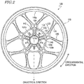
- FIG. 2 and FIG. 3 are respectively a left side view and a right side view schematically showing the wheel 100.
- FIG. 4 is a plan view of the wheel 100 as seen in a diametrical direction thereof.
- the wheel 100 is produced of a magnesium alloy by die casting. Namely, the wheel 100 is a diecast wheel of a magnesium alloy. As a material of the wheel 100, a magnesium alloy having any of various known compositions is usable. As shown in FIG. 2 , FIG. 3 and FIG. 4 , the wheel 100 includes the rim 110, a hub 120 and a plurality of spokes 130.
- the rim 110 is ring-shaped and extends in a circumferential direction.
- the rim 110 has an inner circumferential surface 110a and an outer circumferential surface 110b.
- the tire 27a is attached to the outer circumferential surface 110b of the rim 110.
- the hub 120 includes an inner cylinder 121 through which an axle is inserted, and an outer cylinder 122 enclosing the inner cylinder 121.
- the inner cylinder 121 is generally cylindrical and has an inner circumferential surface 121a and an outer circumferential surface 121b.
- the axle is inserted through a hole (axle insertion hole) defined by the inner circumferential surface 121a of the inner cylinder 121.
- the outer cylinder 122 is generally cylindrical, and has an inner circumferential surface 122a and an outer circumferential surface 122b.
- the hub 120 further includes a coupling portion 123 coupling the inner cylinder 121 and the outer cylinder 122 to each other, a damper accommodation portion 124 accommodating a plurality of dampers (not shown in any of FIG. 1 through FIG. 4 ), and a plurality of ribs 140 provided in the damper accommodation portion 124.
- the damper accommodation portion 124 is a space defined by the inner cylinder 121, the outer cylinder 122 and the coupling portion 123. In the example shown in the figures, the damper accommodation portion 124 is located on the left side in the wheel 100.
- the plurality of ribs 140 are each in engagement with one of the plurality of dampers as described below. In the example shown in the figures, five ribs 140 are provided in the damper accommodation portion 124.
- the damper accommodation portion 124 may be considered as being divided into five regions by the five ribs 140. The number of the plurality of ribs 140 is not limited to five as in this embodiment.
- the hub 120 having the above-described structure is integrally formed. Namely, in this embodiment, no damper housing formed separately from the hub 120 is attached.
- the plurality of spokes 130 couples the rim 110 and the hub 120 to each other. More specifically, the plurality of spokes 130 couples the inner circumferential surface 121a of the rim 121 and the outer circumferential surface 122b of the outer cylinder 122 of the hub 120 to each other.
- the wheel 100 includes ten spokes 130. The number of the plurality of spokes 130 is not limited to ten. In the example shown in the figures, each two spokes 130 adjacent to each other are integrated with each other on the hub 120 side. The spokes 130 are not limited to having such a structure.
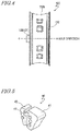
- FIG. 5 shows a damper 40 accommodated in the damper accommodation portion 124.
- the damper 40 includes a first elastic body 41, a second elastic body 42 smaller than the first elastic body 41, and a bridge 43 coupling the first elastic body 41 and the second elastic body 42 to each other.
- FIG. 6 shows a state in which a plurality of the dampers 40 are accommodated in the damper accommodation portion 124.
- the dampers 40 are each located such that the bridge 43 strides over the corresponding rib 140, and are each in engagement with the corresponding rib 140.
- the damper accommodation portion 124 is divided into five regions by the five ribs 140. In each of the five regions, the first elastic body 41 of one of the dampers 40 and the second elastic body 42 of another one of the dampers 40 are located.
- a driven flange 50 and a driven sprocket 60 shown in FIG. 7 are located in the vicinity of the damper accommodation portion 124, in which the dampers 40 are accommodated.
- the driven flange 50 includes a ring-shaped flange main body 51 and a plurality of protrusions (claws) 52 protruding inward in an axle direction from the flange main body 51.
- the driven flange 50 is located such that each of the protrusions 52 are located between two adjacent dampers 40.
- the driven sprocket 60 is tightened to an outer side surface, in the axle direction, of the flange main body 51 of the driven flange 50 by, for example, a bolt (not shown).
- FIG. 8 is a perspective view of the hub 120 and the vicinity thereof as seen from the left.
- FIG. 9 and FIG. 10 are respectively cross-sectional views of the wheel 100 taken along line IX-IX' and line X-X' in FIG. 8 .
- each of the plurality of ribs 140 does not have a simple plate-like shape.
- the ribs 140 each include a pair of first longitudinal walls 141, a lateral wall 143, and at least one second longitudinal wall 142.
- first longitudinal walls 141 protrude outward in the axle direction from the coupling portion 123.
- the pair of first longitudinal walls 141 are located with a predetermined interval being provided therebetween and extend in the diametrical direction of the wheel 100.
- the lateral wall 143 extends in a direction crossing the axle direction (typically, a direction generally perpendicular to the axle direction).
- the lateral wall 143 connects the pair of first longitudinal walls 141 to each other.
- the lateral wall 143 connects middle portions, in the axle direction, of the pair of first longitudinal walls 141 to each other.
- the at least one second longitudinal wall (also called “second axle-direction walls”) 142 includes two second longitudinal walls 142 in this embodiment.
- the second longitudinal walls 142 each protrude outward in the axle direction from the lateral wall 143.
- the second longitudinal walls 142 each extend in the circumferential direction of the wheel 100 and connect the pair of first longitudinal walls 141 to each other.
- the plurality of ribs 140 each include a plurality of recessed portions 140a.
- the plurality of recessed portions 140a are three recessed portions defined by the pair of first longitudinal walls 141, the two second longitudinal walls 142 and the lateral wall 143, the inner cylinder 121 and the outer cylinder 122.
- the recessed portions 140a are each recessed inward in the axle direction. In other words, the recessed portions 140a are each opened outward in the axle direction.
- the hub 120 including the damper accommodation portion 124 is integrally formed. Therefore, as compared with in the case where the damper accommodation portion 124 is formed separately from the hub 120, the production cost and the number of the parts may be decreased, and the weight of the diecast wheel 100 may be decreased.
- the ribs 140 provided in the damper accommodation portion 124 each include the pair of first longitudinal walls 141 extending in the diametrical direction and the lateral wall 143 extending in a direction crossing the axle direction and connecting the pair of first longitudinal walls 141 to each other.
- the ribs 140 do not have a simple solid structure, but may have portions removed in a thickness direction from the solid structure. Therefore, the difference in the thickness between the ribs 140 and the other portions of the damper accommodation portion 124 may be decreased, and thus occurrence of cracks may be suppressed.
- the ribs 140 each include at least one second longitudinal wall 142 extending in the circumferential direction and connecting the pair of first longitudinal walls 141 to each other. Therefore, the ribs 140 (and therefore, the damper accommodation portion 124) may be made sufficiently strong. It is not needed to increase the thickness of the portions of the damper accommodation portion 124 other than the ribs 140 in order to suppress the occurrence of the cracks. Therefore, the diecast wheel 100 may be made sufficiently lightweight.
- the diecast wheel 100 formed of a magnesium alloy in which the damper accommodation portion 124 is integrated with the hub 120 and the like a decrease in the casting quality may be suppressed, and the damper accommodation portion 124 may be made sufficiently strong while the diecast wheel 100 may be made sufficiently lightweight.
- the position of the lateral wall 143 in the axle direction is not limited to the position shown in the example in FIG. 10 and the like.
- FIG. 11 and FIG. 12 show another example of the position of the lateral wall 143.
- the lateral wall 143 connects top ends of the pair of first longitudinal walls 141 to each other. Therefore, the second longitudinal walls 142 protrude inward in the axle direction from the lateral wall 143. Even in the case where the structure shown in FIG. 11 and FIG. 12 is adopted, the occurrence of the cracks may be suppressed while the wheel 100 may be made sufficiently lightweight.
- the ribs 140 each include the plurality of recessed portions 140a defined by the pair of first longitudinal walls 141, the at least one second longitudinal wall 142 and the lateral wall 143 of the rib 140 and the inner cylinder 121 and the outer cylinder 122 of the hub 120 (recessed portions 140a recessed inward in the axle direction).
- the lateral wall 143 of the rib 140 connects portions, other than the top ends, of the pair of first longitudinal walls 141 to each other.
- a step of inspecting a rear surface of the damper accommodation portion 124 (the rear surface is an outer surface of the wheel 100) is performed.
- the ribs 140 do not include the recessed portions 140a described above, namely, in the case where the lateral wall 143 connects the top ends of the pair of first longitudinal walls 141 to each other as shown in FIG. 11 and FIG. 12 , a surface inspection tool may not easily reach a rear surface of the lateral wall 143.
- the surface inspection tool easily reaches the rear surface of the lateral wall 143. Therefore, the post-casting inspection on the outer surface may be performed in a preferred manner.
- depth d1 of the damper accommodation portion 124 is a distance from a top end of the rib 140 (top end of each of the first longitudinal walls 141) to a surface of the coupling portion 123.
- Depth d2 of the recessed portion 140a is a distance from the top end of the rib 140 (top end of the first longitudinal wall 141) to a surface of the lateral wall 143.
- depth d2 of the recessed portion 140a is greater, the surface inspection tool reaches the rear surface of the lateral wall 143 more easily. Therefore, from the point of view of inspecting the rear surface of the damper accommodation portion 124 in a preferred manner, it is preferred that depth d2 of the recessed portion 140a is great. Specifically, it is preferred that depth d2 of the recessed portion 140a is 10% or more of depth d1 of the damper accommodation portion 124.
- depth d2 of the recessed portion 140a is 70% or less of depth d1 of the damper accommodation portion 124.
- depth d1 of the damper accommodation portion 124 and depth d2 of the recessed portion 140a fulfill the relationship of (0.1) ⁇ d1 ⁇ d2 s (0.7) ⁇ d1.
- thickness t1 of each of the first longitudinal walls 141 see FIG. 10
- thickness t2 of each of the second longitudinal walls 142 see FIG. 9
- thickness t3 of the lateral wall 143 see FIG. 10
- the ribs 140 each receive a stress in the circumferential direction from the corresponding damper 40.
- the second longitudinal walls 142 and the lateral wall 143 play a role of supporting the first longitudinal walls 141 against the stress in the circumferential direction. Therefore, it is preferred that thickness t2 of the second longitudinal wall 142 is greater than thickness t1 of the first longitudinal wall 141. It is preferred that thickness t3 of the lateral wall 143 is greater than thickness t1 of the first longitudinal wall 141.
- Thickness t1 of the first longitudinal wall 141 is, for example, 2 mm or greater and 8 mm or less.
- Thickness t2 of the second longitudinal wall 142 is, for example, 2 mm or greater and 8 mm or less.
- Thickness t3 of the lateral wall 143 is, for example, 2 mm or greater and 8 mm or less.
- width w of each of the ribs 140 there is no specific limitation on the value of width w of the rib 140.
- width w of the rib 140 is relatively great, it is preferred that depth d1 of the damper accommodation portion 124 is greater in order to provide a sufficient capacity of the damper accommodation portion 124 (i.e., in order to provide a sufficient volume of the damper 40 including the first elastic body 41 and the second elastic body 42).
- depth d1 of the damper accommodation portion 124 is 30 mm or greater.
- the ribs 140 each include two second longitudinal walls 142.
- the number of the second longitudinal walls 142 is not limited to two.
- the number of the second longitudinal walls 142 in each rib 140 may be one, or three or greater.
- the motorcycle 1, which is a sporty vehicle is described as an example of straddled vehicle.
- the diecast wheel according to a preferred embodiment may be used for a non-sporty motorcycle 1, or may be used for a three-wheeled or four-wheeled straddled vehicle.
- the diecast wheel 100 is formed of a magnesium alloy and includes the ring-shaped rim 110, the hub 120 including the inner cylinder 121 through which the axle is inserted and the outer cylinder 122 enclosing the inner cylinder 121, and the plurality of spokes 130 coupling the rim 110 and the hub 120 to each other.
- the hub 120 further includes the coupling portion 123 coupling the inner cylinder 121 and the outer cylinder 122 to each other, the damper accommodation portion 124 defined by the inner cylinder 121, the outer cylinder 122 and the coupling portion 123 and accommodating the plurality of dampers 40, and the plurality of ribs 140 provided in the damper accommodation portion 124 and each in engagement with one of the plurality of dampers 40.
- the hub 120 is integrally formed.
- the plurality of ribs 140 each include the pair of first longitudinal walls 141 protruding outward in the axle direction from the coupling portion 123, located with a predetermined interval being provided therebetween, and extending in the diametrical direction of the diecast wheel 100, the lateral wall 143 extending in a direction crossing the axle direction and connecting the pair of first longitudinal walls 141 to each other, and at least one second longitudinal wall 142 protruding outward or inward in the axle direction from the lateral wall 143, extending in the circumferential direction of the diecast wheel 100 and connecting the pair of first longitudinal walls 141 to each other.
- the hub 120 including the damper accommodation portion 124 is integrally formed. Therefore, as compared with in the case where the damper accommodation portion 124 is formed separately from the hub 120, the production cost and the number of the parts may be decreased, and the weight of the diecast wheel 100 may be decreased.
- the ribs 140 provided in the damper accommodation portion 124 each include the pair of first longitudinal walls 141 extending in the diametrical direction and the lateral wall 143 extending in a direction crossing the axle direction and connecting the pair of first longitudinal walls 141 to each other. Namely, the ribs 140 do not have a simple solid structure, but may have portions removed in the thickness direction from the solid structure.
- the difference in the thickness between the ribs 140 and the other portions of the damper accommodation portion 124 may be decreased, and thus the occurrence of the cracks may be suppressed.
- the ribs 140 each include at least one second longitudinal wall 142 extending in the circumferential direction and connecting the pair of first longitudinal walls 141 to each other. Therefore, the ribs 140 (and therefore, the damper accommodation portion 124) may be made sufficiently strong. It is not needed to increase the thickness of the portions of the damper accommodation portion 124 other than the ribs 140 in order to suppress the occurrence of the cracks. Therefore, the diecast wheel 100 may be made sufficiently lightweight.
- the diecast wheel 100 formed of a magnesium alloy in which the damper accommodation portion 124 is integrated with the hub 120 and the like a decrease in the casting quality may be suppressed, and the damper accommodation portion 124 may be made sufficiently strong while the diecast wheel 100 may be made sufficiently lightweight.
- the plurality of ribs 140 each include the plurality of recessed portions 140a defined by the pair of first longitudinal walls 141, the at least one second longitudinal wall 142, the lateral wall 143, the inner cylinder 121 and the outer cylinder 122.
- the ribs 140 each include the plurality of recessed portions 140a defined by the pair of first longitudinal walls 141, the at least one second longitudinal wall 142 and the lateral wall 143 of the rib 140 and the inner cylinder 121 and the outer cylinder 122 of the hub 120.
- the lateral wall 143 of the rib 140 connects portions, other than the top ends, of the pair of first longitudinal walls 141 to each other.
- the surface inspection tool may not easily reach the rear surface of the lateral wall 143.
- the surface inspection tool easily reaches the rear surface of the lateral wall 143. Therefore, the post-casting inspection on the outer surface may be performed in a preferred manner.
- depth d1 of the damper accommodation portion 124 and depth d2 of each of the plurality of recessed portions 140a fulfill the relationship of (0.1) ⁇ d1 ⁇ d2 ⁇ (0.7) ⁇ d1.
- depth d2 of the recessed portion 140a is great. Specifically, it is preferred that depth d2 of the recessed portion 140a is 10% or more of depth d1 of the damper accommodation portion 124. However, if depth d2 of the recessed portion 140a is too great, namely, if the lateral wall 143 is too close to the bottom end of the first longitudinal wall 141, a portion of the mold corresponding to the recessed portion 140a becomes too lengthy, which may make it difficult to perform die casting in a preferred manner.
- depth d2 of the recessed portion 140a is 70% or less of depth d1 of the damper accommodation portion 124.
- depth d1 of the damper accommodation portion 124 and depth d2 of the recessed portion 140a fulfill the relationship of (0.1) ⁇ d1 ⁇ d2 ⁇ (0.7) ⁇ d1.
- thickness t2 of the at least one second longitudinal wall 142 is greater than thickness t1 of each of the pair of first longitudinal walls 141.
- the ribs 140 each receive a stress in the circumferential direction from the corresponding damper 40. Therefore, it is preferred that thickness t2 of the second longitudinal wall 142 is greater than thickness t1 of the first longitudinal wall 141.
- thickness t3 of the lateral wall 143 is greater than thickness t1 of each of the pair of first longitudinal walls 141.
- thickness t3 of the lateral wall 143 is greater than thickness t1 of the first longitudinal wall 141 for the same reason regarding thickness t2 of the at least one second longitudinal wall 142.
- width w of each of the plurality of ribs 140 is 15 mm or greater, and depth d1 of the damper accommodation portion 124 is 30 mm or greater.
- width w of the rib 140 there is no specific limitation on the value of width w of the rib 140. In the case where width w of the rib 140 is relatively great, it is preferred that depth d1 of the damper accommodation portion 124 is greater in order to provide a sufficient capacity of the damper accommodation portion 124 (i.e., in order to provide a sufficient volume of the damper 40, which is an elastic body). Specifically, in the case where width w of the rib 140 is 15 mm or greater, it is preferred that depth d1 of the damper accommodation portion 124 is 30 mm or greater.
- the straddled vehicle 1 includes the diecast wheel 100 having any one of the above-described structures.
- the diecast wheel 100 is preferably usable for various types of straddled vehicles including a motorcycle 1.
- a decrease in the casting quality may be suppressed, and the damper accommodation portion may be made sufficiently strong while the diecast wheel may be made sufficiently lightweight.
- a diecast wheel according to a preferred embodiment is preferably usable for various types of straddled vehicles including a motorcycle.
Landscapes
- Engineering & Computer Science (AREA)
- Mechanical Engineering (AREA)
- Vehicle Body Suspensions (AREA)
Claims (9)
- Roue coulée sous pression (100) formée d'un alliage de magnésium, comprenant :une jante annulaire (110) coaxiale à une direction axiale d'un essieu ;un moyeu (120) coaxial à la jante annulaire (110) et comprenant un cylindre intérieur (121) configuré pour insérer l'essieu et un cylindre extérieur (122) entourant coaxialement le cylindre intérieur (121) ; etune pluralité de rayons (130) couplant la jante (110) et le moyeu (120) l'un à l'autre dans une direction diamétrale de la roue coulée sous pression (100),dans laquelle le moyeu (120) comprend en outre :une partie de couplage (123) couplant le cylindre intérieur (121) et le cylindre extérieur (122) l'un à l'autre,une partie de réception d'amortisseurs (124) définie par le cylindre intérieur (121), le cylindre extérieur (122) et la partie de couplage (123), la partie de réception d'amortisseurs (124) est configurée pour recevoir une pluralité d'amortisseurs (40), etune pluralité de nervures (140) situées dans la partie de réception d'amortisseurs (124), chacune de la pluralité de nervures (140) étant configurée pour se mettre en prise avec l'un de la pluralité des amortisseurs (40),caractérisée en ce que le moyeu (120) est formé d'un seul bloc, et en ce que chacune de la pluralité de nervures (140) comprend :une paire de premières parois longitudinales (141) saillantes vers un premier côté dans la direction d'essieu à partir de la partie de couplage (123), la paire de premières parois longitudinales (141) étant agencée de façon qu'un intervalle prédéterminé soit ménagé entre elles et s'étendant dans une direction diamétrale de la roue coulée sous pression (100),une paroi latérale (143) s'étendant dans une direction qui coupe la direction d'essieu et reliant la paire de premières parois longitudinales (141) l'une à l'autre, etau moins une seconde paroi longitudinale (142) saillante vers ledit premier côté ou un second côté opposé au premier côté dans la direction d'essieu à partir de la paroi latérale (143), l'au moins une seconde paroi longitudinale (142) s'étendant dans une direction circonférentielle de la roue coulée sous pression (100) et reliant la paire de premières parois longitudinales (141) l'une à l'autre.
- Roue coulée sous pression (100) selon la revendication 1, dans laquelle chacune de la pluralité de nervures (140) comprend une pluralité de parties en creux (140a) définies par la paire de premières parois longitudinales (141), l'au moins une seconde paroi longitudinale (142), la paroi latérale (143), le cylindre intérieur (121) et le cylindre extérieur (122).
- Roue coulée sous pression (100) selon la revendication 2, dans laquelle une profondeur (d1) de la partie de réception d'amortisseurs (124) dans la direction d'essieu et une profondeur (d2) de chacune de la pluralité de parties en creux (140a) dans la direction d'essieu satisfont cette
relation : (0,1) · d1 ≤ d2 ≤ (0,7) · d1. - Roue coulée sous pression (100) selon l'une quelconque des revendications 1 à 3, dans laquelle une épaisseur (t2) de l'au moins une seconde paroi longitudinale (142) dans une direction diamétrale est supérieure à une épaisseur (t1) de chacune de la paire de premières parois longitudinales (141) dans une direction perpendiculaire à la direction axiale et à la direction diamétrale.
- Roue coulée sous pression (100) selon l'une quelconque des revendications 1 à 4, dans laquelle une épaisseur (t3) de la paroi latérale (143) dans la direction d'essieu est supérieure à l'épaisseur (t1) de chacune de la paire de premières parois longitudinales (141) dans une direction perpendiculaire à la direction axiale et à la direction diamétrale.
- Roue coulée sous pression (100) selon l'une quelconque des revendications 1 à 5, dans laquelle une largeur (w) de chacune de la pluralité de nervures (140) dans une direction perpendiculaire à la direction axiale et à la direction diamétrale est supérieure ou égale à 15 mm, et une profondeur (d1) de la partie de réception d'amortisseurs (124) dans la direction d'essieu est supérieure ou égale à 30 mm.
- Unité roue comprenant la roue coulée sous pression (100) selon l'une quelconque des revendications 1 à 6, dans laquelle chacune des parties de réception d'amortisseurs (124) reçoit un amortisseur (40) de la pluralité d'amortisseurs (40).
- Unité roue selon la revendication 7, dans laquelle l'amortisseur (40) comprend un premier corps élastique (41), un second corps élastique (42) plus petit que le premier corps élastique (41), et un pont (43) couplant le premier corps élastique (41) et le second corps élastique (42) l'un à l'autre.
- Véhicule à enfourcher comprenant la roue coulée sous pression (100) selon l'une quelconque des revendications 1 à 6 ou l'unité roue selon la revendication 7 ou 8.
Applications Claiming Priority (1)
| Application Number | Priority Date | Filing Date | Title |
|---|---|---|---|
| JP2019079752A JP2020175792A (ja) | 2019-04-19 | 2019-04-19 | ダイカストホイールおよび鞍乗型車両 |
Publications (2)
| Publication Number | Publication Date |
|---|---|
| EP3725540A1 EP3725540A1 (fr) | 2020-10-21 |
| EP3725540B1 true EP3725540B1 (fr) | 2021-09-15 |
Family
ID=69844695
Family Applications (1)
| Application Number | Title | Priority Date | Filing Date |
|---|---|---|---|
| EP20163353.4A Not-in-force EP3725540B1 (fr) | 2019-04-19 | 2020-03-16 | Roue coulée sous pression, unité de roue et véhicule à enfourcher |
Country Status (2)
| Country | Link |
|---|---|
| EP (1) | EP3725540B1 (fr) |
| JP (1) | JP2020175792A (fr) |
Family Cites Families (4)
| Publication number | Priority date | Publication date | Assignee | Title |
|---|---|---|---|---|
| JP2007118684A (ja) | 2005-10-26 | 2007-05-17 | Yamaha Motor Co Ltd | 自動二輪車のホイール及びその製造方法 |
| JP5361782B2 (ja) * | 2010-03-31 | 2013-12-04 | 本田技研工業株式会社 | 鞍乗り型車両のホイール構造 |
| JP5911058B2 (ja) * | 2012-02-09 | 2016-04-27 | 本田技研工業株式会社 | 自動二輪車用ホイール |
| EP3135573B1 (fr) * | 2015-07-17 | 2018-07-04 | Yamaha Hatsudoki Kabushiki Kaisha | Roue pour véhicules à califourchon et véhicule à califourchon |
-
2019
- 2019-04-19 JP JP2019079752A patent/JP2020175792A/ja active Pending
-
2020
- 2020-03-16 EP EP20163353.4A patent/EP3725540B1/fr not_active Not-in-force
Also Published As
| Publication number | Publication date |
|---|---|
| EP3725540A1 (fr) | 2020-10-21 |
| JP2020175792A (ja) | 2020-10-29 |
Similar Documents
| Publication | Publication Date | Title |
|---|---|---|
| EP3172059B1 (fr) | Roue en aluminium coulé | |
| EP2767453B1 (fr) | Colonne de direction et son procédé de production | |
| US9776660B2 (en) | Vehicle subframe | |
| US8272656B2 (en) | Frame structure of a vehicle | |
| JP4519632B2 (ja) | 二輪車用のフレーム | |
| JP6679783B2 (ja) | ステアリングホイールの芯金の製造方法 | |
| EP1780048B1 (fr) | Roue pour motocycle et son procédé de fabrication | |
| JP5462523B2 (ja) | 互いに異なる材質成分の金属部品同士の一体化構造及びその製造方法 | |
| JP4119334B2 (ja) | バランスウエイトおよびスポークホイールのバランス補正構造 | |
| EP3725540A1 (fr) | Roue coulée sous pression, unité de roue et véhicule à enfourcher | |
| EP2626217B1 (fr) | Roue pour motocyclette | |
| US20180037258A1 (en) | Wheel mount | |
| EP3366562B1 (fr) | Structure de bras oscillant pour véhicule à enfourcher | |
| JP5157470B2 (ja) | 自動二輪車のリヤスイングアームおよびその製造方法 | |
| JP4276144B2 (ja) | 自動2輪車用ホイール及びその製法 | |
| JPWO2017056234A1 (ja) | シャフトの軸受構造 | |
| EP3115290B1 (fr) | Bras arrière, véhicule à selle et procédé de fabrication | |
| JP6572708B2 (ja) | スイングアーム | |
| JP6944484B2 (ja) | 車両用支持構造体および車両用支持構造体の製造方法 | |
| JP2003320801A (ja) | 自動二輪車用ホイール | |
| JP6904898B2 (ja) | フレーム構造 | |
| CN100534852C (zh) | 机车的车架结构 | |
| JP7308781B2 (ja) | 芯金及び芯金の製造方法 | |
| CN109969317B (zh) | 框架结构 | |
| JPH011679A (ja) | 自動2輪車用リヤスイングア−ム |
Legal Events
| Date | Code | Title | Description |
|---|---|---|---|
| PUAI | Public reference made under article 153(3) epc to a published international application that has entered the european phase |
Free format text: ORIGINAL CODE: 0009012 |
|
| STAA | Information on the status of an ep patent application or granted ep patent |
Free format text: STATUS: REQUEST FOR EXAMINATION WAS MADE |
|
| 17P | Request for examination filed |
Effective date: 20200316 |
|
| AK | Designated contracting states |
Kind code of ref document: A1 Designated state(s): AL AT BE BG CH CY CZ DE DK EE ES FI FR GB GR HR HU IE IS IT LI LT LU LV MC MK MT NL NO PL PT RO RS SE SI SK SM TR |
|
| AX | Request for extension of the european patent |
Extension state: BA ME |
|
| RBV | Designated contracting states (corrected) |
Designated state(s): AL AT BE BG CH CY CZ DE DK EE ES FI FR GB GR HR HU IE IS IT LI LT LU LV MC MK MT NL NO PL PT RO RS SE SI SK SM TR |
|
| RIC1 | Information provided on ipc code assigned before grant |
Ipc: B62M 21/00 20060101ALI20210415BHEP Ipc: B60B 1/08 20060101ALI20210415BHEP Ipc: B60B 27/04 20060101ALI20210415BHEP Ipc: B60B 27/02 20060101ALI20210415BHEP Ipc: B60B 3/06 20060101ALI20210415BHEP Ipc: B60B 1/00 20060101AFI20210415BHEP |
|
| GRAP | Despatch of communication of intention to grant a patent |
Free format text: ORIGINAL CODE: EPIDOSNIGR1 |
|
| STAA | Information on the status of an ep patent application or granted ep patent |
Free format text: STATUS: GRANT OF PATENT IS INTENDED |
|
| INTG | Intention to grant announced |
Effective date: 20210528 |
|
| GRAS | Grant fee paid |
Free format text: ORIGINAL CODE: EPIDOSNIGR3 |
|
| GRAA | (expected) grant |
Free format text: ORIGINAL CODE: 0009210 |
|
| STAA | Information on the status of an ep patent application or granted ep patent |
Free format text: STATUS: THE PATENT HAS BEEN GRANTED |
|
| AK | Designated contracting states |
Kind code of ref document: B1 Designated state(s): AL AT BE BG CH CY CZ DE DK EE ES FI FR GB GR HR HU IE IS IT LI LT LU LV MC MK MT NL NO PL PT RO RS SE SI SK SM TR |
|
| REG | Reference to a national code |
Ref country code: CH Ref legal event code: EP |
|
| REG | Reference to a national code |
Ref country code: DE Ref legal event code: R096 Ref document number: 602020000541 Country of ref document: DE |
|
| REG | Reference to a national code |
Ref country code: IE Ref legal event code: FG4D |
|
| REG | Reference to a national code |
Ref country code: AT Ref legal event code: REF Ref document number: 1430241 Country of ref document: AT Kind code of ref document: T Effective date: 20211015 |
|
| REG | Reference to a national code |
Ref country code: LT Ref legal event code: MG9D |
|
| REG | Reference to a national code |
Ref country code: NL Ref legal event code: MP Effective date: 20210915 |
|
| PG25 | Lapsed in a contracting state [announced via postgrant information from national office to epo] |
Ref country code: RS Free format text: LAPSE BECAUSE OF FAILURE TO SUBMIT A TRANSLATION OF THE DESCRIPTION OR TO PAY THE FEE WITHIN THE PRESCRIBED TIME-LIMIT Effective date: 20210915 Ref country code: SE Free format text: LAPSE BECAUSE OF FAILURE TO SUBMIT A TRANSLATION OF THE DESCRIPTION OR TO PAY THE FEE WITHIN THE PRESCRIBED TIME-LIMIT Effective date: 20210915 Ref country code: NO Free format text: LAPSE BECAUSE OF FAILURE TO SUBMIT A TRANSLATION OF THE DESCRIPTION OR TO PAY THE FEE WITHIN THE PRESCRIBED TIME-LIMIT Effective date: 20211215 Ref country code: HR Free format text: LAPSE BECAUSE OF FAILURE TO SUBMIT A TRANSLATION OF THE DESCRIPTION OR TO PAY THE FEE WITHIN THE PRESCRIBED TIME-LIMIT Effective date: 20210915 Ref country code: FI Free format text: LAPSE BECAUSE OF FAILURE TO SUBMIT A TRANSLATION OF THE DESCRIPTION OR TO PAY THE FEE WITHIN THE PRESCRIBED TIME-LIMIT Effective date: 20210915 Ref country code: BG Free format text: LAPSE BECAUSE OF FAILURE TO SUBMIT A TRANSLATION OF THE DESCRIPTION OR TO PAY THE FEE WITHIN THE PRESCRIBED TIME-LIMIT Effective date: 20211215 Ref country code: LT Free format text: LAPSE BECAUSE OF FAILURE TO SUBMIT A TRANSLATION OF THE DESCRIPTION OR TO PAY THE FEE WITHIN THE PRESCRIBED TIME-LIMIT Effective date: 20210915 |
|
| REG | Reference to a national code |
Ref country code: AT Ref legal event code: MK05 Ref document number: 1430241 Country of ref document: AT Kind code of ref document: T Effective date: 20210915 |
|
| PG25 | Lapsed in a contracting state [announced via postgrant information from national office to epo] |
Ref country code: LV Free format text: LAPSE BECAUSE OF FAILURE TO SUBMIT A TRANSLATION OF THE DESCRIPTION OR TO PAY THE FEE WITHIN THE PRESCRIBED TIME-LIMIT Effective date: 20210915 Ref country code: GR Free format text: LAPSE BECAUSE OF FAILURE TO SUBMIT A TRANSLATION OF THE DESCRIPTION OR TO PAY THE FEE WITHIN THE PRESCRIBED TIME-LIMIT Effective date: 20211216 |
|
| PG25 | Lapsed in a contracting state [announced via postgrant information from national office to epo] |
Ref country code: AT Free format text: LAPSE BECAUSE OF FAILURE TO SUBMIT A TRANSLATION OF THE DESCRIPTION OR TO PAY THE FEE WITHIN THE PRESCRIBED TIME-LIMIT Effective date: 20210915 |
|
| PGFP | Annual fee paid to national office [announced via postgrant information from national office to epo] |
Ref country code: DE Payment date: 20220322 Year of fee payment: 3 |
|
| PG25 | Lapsed in a contracting state [announced via postgrant information from national office to epo] |
Ref country code: IS Free format text: LAPSE BECAUSE OF FAILURE TO SUBMIT A TRANSLATION OF THE DESCRIPTION OR TO PAY THE FEE WITHIN THE PRESCRIBED TIME-LIMIT Effective date: 20220115 Ref country code: SM Free format text: LAPSE BECAUSE OF FAILURE TO SUBMIT A TRANSLATION OF THE DESCRIPTION OR TO PAY THE FEE WITHIN THE PRESCRIBED TIME-LIMIT Effective date: 20210915 Ref country code: SK Free format text: LAPSE BECAUSE OF FAILURE TO SUBMIT A TRANSLATION OF THE DESCRIPTION OR TO PAY THE FEE WITHIN THE PRESCRIBED TIME-LIMIT Effective date: 20210915 Ref country code: RO Free format text: LAPSE BECAUSE OF FAILURE TO SUBMIT A TRANSLATION OF THE DESCRIPTION OR TO PAY THE FEE WITHIN THE PRESCRIBED TIME-LIMIT Effective date: 20210915 Ref country code: PT Free format text: LAPSE BECAUSE OF FAILURE TO SUBMIT A TRANSLATION OF THE DESCRIPTION OR TO PAY THE FEE WITHIN THE PRESCRIBED TIME-LIMIT Effective date: 20220117 Ref country code: PL Free format text: LAPSE BECAUSE OF FAILURE TO SUBMIT A TRANSLATION OF THE DESCRIPTION OR TO PAY THE FEE WITHIN THE PRESCRIBED TIME-LIMIT Effective date: 20210915 Ref country code: NL Free format text: LAPSE BECAUSE OF FAILURE TO SUBMIT A TRANSLATION OF THE DESCRIPTION OR TO PAY THE FEE WITHIN THE PRESCRIBED TIME-LIMIT Effective date: 20210915 Ref country code: ES Free format text: LAPSE BECAUSE OF FAILURE TO SUBMIT A TRANSLATION OF THE DESCRIPTION OR TO PAY THE FEE WITHIN THE PRESCRIBED TIME-LIMIT Effective date: 20210915 Ref country code: EE Free format text: LAPSE BECAUSE OF FAILURE TO SUBMIT A TRANSLATION OF THE DESCRIPTION OR TO PAY THE FEE WITHIN THE PRESCRIBED TIME-LIMIT Effective date: 20210915 Ref country code: CZ Free format text: LAPSE BECAUSE OF FAILURE TO SUBMIT A TRANSLATION OF THE DESCRIPTION OR TO PAY THE FEE WITHIN THE PRESCRIBED TIME-LIMIT Effective date: 20210915 Ref country code: AL Free format text: LAPSE BECAUSE OF FAILURE TO SUBMIT A TRANSLATION OF THE DESCRIPTION OR TO PAY THE FEE WITHIN THE PRESCRIBED TIME-LIMIT Effective date: 20210915 |
|
| PGFP | Annual fee paid to national office [announced via postgrant information from national office to epo] |
Ref country code: FR Payment date: 20220322 Year of fee payment: 3 |
|
| REG | Reference to a national code |
Ref country code: DE Ref legal event code: R097 Ref document number: 602020000541 Country of ref document: DE |
|
| PLBE | No opposition filed within time limit |
Free format text: ORIGINAL CODE: 0009261 |
|
| STAA | Information on the status of an ep patent application or granted ep patent |
Free format text: STATUS: NO OPPOSITION FILED WITHIN TIME LIMIT |
|
| PG25 | Lapsed in a contracting state [announced via postgrant information from national office to epo] |
Ref country code: DK Free format text: LAPSE BECAUSE OF FAILURE TO SUBMIT A TRANSLATION OF THE DESCRIPTION OR TO PAY THE FEE WITHIN THE PRESCRIBED TIME-LIMIT Effective date: 20210915 |
|
| 26N | No opposition filed |
Effective date: 20220616 |
|
| PG25 | Lapsed in a contracting state [announced via postgrant information from national office to epo] |
Ref country code: SI Free format text: LAPSE BECAUSE OF FAILURE TO SUBMIT A TRANSLATION OF THE DESCRIPTION OR TO PAY THE FEE WITHIN THE PRESCRIBED TIME-LIMIT Effective date: 20210915 |
|
| PG25 | Lapsed in a contracting state [announced via postgrant information from national office to epo] |
Ref country code: MC Free format text: LAPSE BECAUSE OF FAILURE TO SUBMIT A TRANSLATION OF THE DESCRIPTION OR TO PAY THE FEE WITHIN THE PRESCRIBED TIME-LIMIT Effective date: 20210915 |
|
| REG | Reference to a national code |
Ref country code: BE Ref legal event code: MM Effective date: 20220331 |
|
| PG25 | Lapsed in a contracting state [announced via postgrant information from national office to epo] |
Ref country code: LU Free format text: LAPSE BECAUSE OF NON-PAYMENT OF DUE FEES Effective date: 20220316 Ref country code: IE Free format text: LAPSE BECAUSE OF NON-PAYMENT OF DUE FEES Effective date: 20220316 |
|
| PG25 | Lapsed in a contracting state [announced via postgrant information from national office to epo] |
Ref country code: BE Free format text: LAPSE BECAUSE OF NON-PAYMENT OF DUE FEES Effective date: 20220331 |
|
| PGFP | Annual fee paid to national office [announced via postgrant information from national office to epo] |
Ref country code: IT Payment date: 20230331 Year of fee payment: 4 |
|
| REG | Reference to a national code |
Ref country code: DE Ref legal event code: R119 Ref document number: 602020000541 Country of ref document: DE |
|
| REG | Reference to a national code |
Ref country code: CH Ref legal event code: PL |
|
| PG25 | Lapsed in a contracting state [announced via postgrant information from national office to epo] |
Ref country code: LI Free format text: LAPSE BECAUSE OF NON-PAYMENT OF DUE FEES Effective date: 20230331 Ref country code: FR Free format text: LAPSE BECAUSE OF NON-PAYMENT OF DUE FEES Effective date: 20230331 Ref country code: DE Free format text: LAPSE BECAUSE OF NON-PAYMENT OF DUE FEES Effective date: 20231003 Ref country code: CH Free format text: LAPSE BECAUSE OF NON-PAYMENT OF DUE FEES Effective date: 20230331 |
|
| PG25 | Lapsed in a contracting state [announced via postgrant information from national office to epo] |
Ref country code: MK Free format text: LAPSE BECAUSE OF FAILURE TO SUBMIT A TRANSLATION OF THE DESCRIPTION OR TO PAY THE FEE WITHIN THE PRESCRIBED TIME-LIMIT Effective date: 20210915 Ref country code: CY Free format text: LAPSE BECAUSE OF FAILURE TO SUBMIT A TRANSLATION OF THE DESCRIPTION OR TO PAY THE FEE WITHIN THE PRESCRIBED TIME-LIMIT Effective date: 20210915 |
|
| PG25 | Lapsed in a contracting state [announced via postgrant information from national office to epo] |
Ref country code: HU Free format text: LAPSE BECAUSE OF FAILURE TO SUBMIT A TRANSLATION OF THE DESCRIPTION OR TO PAY THE FEE WITHIN THE PRESCRIBED TIME-LIMIT; INVALID AB INITIO Effective date: 20200316 |
|
| PG25 | Lapsed in a contracting state [announced via postgrant information from national office to epo] |
Ref country code: TR Free format text: LAPSE BECAUSE OF FAILURE TO SUBMIT A TRANSLATION OF THE DESCRIPTION OR TO PAY THE FEE WITHIN THE PRESCRIBED TIME-LIMIT Effective date: 20210915 |
|
| PG25 | Lapsed in a contracting state [announced via postgrant information from national office to epo] |
Ref country code: MT Free format text: LAPSE BECAUSE OF FAILURE TO SUBMIT A TRANSLATION OF THE DESCRIPTION OR TO PAY THE FEE WITHIN THE PRESCRIBED TIME-LIMIT Effective date: 20210915 |
|
| GBPC | Gb: european patent ceased through non-payment of renewal fee |
Effective date: 20240316 |
|
| PG25 | Lapsed in a contracting state [announced via postgrant information from national office to epo] |
Ref country code: GB Free format text: LAPSE BECAUSE OF NON-PAYMENT OF DUE FEES Effective date: 20240316 |
|
| PG25 | Lapsed in a contracting state [announced via postgrant information from national office to epo] |
Ref country code: GB Free format text: LAPSE BECAUSE OF NON-PAYMENT OF DUE FEES Effective date: 20240316 |
|
| PG25 | Lapsed in a contracting state [announced via postgrant information from national office to epo] |
Ref country code: IT Free format text: LAPSE BECAUSE OF NON-PAYMENT OF DUE FEES Effective date: 20240316 |