EP3135584A1 - Frachtumschlagsystem - Google Patents
Frachtumschlagsystem Download PDFInfo
- Publication number
- EP3135584A1 EP3135584A1 EP16179969.7A EP16179969A EP3135584A1 EP 3135584 A1 EP3135584 A1 EP 3135584A1 EP 16179969 A EP16179969 A EP 16179969A EP 3135584 A1 EP3135584 A1 EP 3135584A1
- Authority
- EP
- European Patent Office
- Prior art keywords
- pdu
- pmm
- braking function
- braking
- cargo
- Prior art date
- Legal status (The legal status is an assumption and is not a legal conclusion. Google has not performed a legal analysis and makes no representation as to the accuracy of the status listed.)
- Granted
Links
Images




Classifications
-
- B—PERFORMING OPERATIONS; TRANSPORTING
- B65—CONVEYING; PACKING; STORING; HANDLING THIN OR FILAMENTARY MATERIAL
- B65G—TRANSPORT OR STORAGE DEVICES, e.g. CONVEYORS FOR LOADING OR TIPPING, SHOP CONVEYOR SYSTEMS OR PNEUMATIC TUBE CONVEYORS
- B65G13/00—Roller-ways
-
- B—PERFORMING OPERATIONS; TRANSPORTING
- B65—CONVEYING; PACKING; STORING; HANDLING THIN OR FILAMENTARY MATERIAL
- B65G—TRANSPORT OR STORAGE DEVICES, e.g. CONVEYORS FOR LOADING OR TIPPING, SHOP CONVEYOR SYSTEMS OR PNEUMATIC TUBE CONVEYORS
- B65G13/00—Roller-ways
- B65G13/075—Braking means
-
- B—PERFORMING OPERATIONS; TRANSPORTING
- B64—AIRCRAFT; AVIATION; COSMONAUTICS
- B64D—EQUIPMENT FOR FITTING IN OR TO AIRCRAFT; FLIGHT SUITS; PARACHUTES; ARRANGEMENT OR MOUNTING OF POWER PLANTS OR PROPULSION TRANSMISSIONS IN AIRCRAFT
- B64D9/00—Equipment for handling freight; Equipment for facilitating passenger embarkation or the like
-
- B—PERFORMING OPERATIONS; TRANSPORTING
- B65—CONVEYING; PACKING; STORING; HANDLING THIN OR FILAMENTARY MATERIAL
- B65G—TRANSPORT OR STORAGE DEVICES, e.g. CONVEYORS FOR LOADING OR TIPPING, SHOP CONVEYOR SYSTEMS OR PNEUMATIC TUBE CONVEYORS
- B65G13/00—Roller-ways
- B65G13/02—Roller-ways having driven rollers
- B65G13/06—Roller driving means
- B65G13/071—Roller driving means with frictional engagement
-
- H—ELECTRICITY
- H02—GENERATION; CONVERSION OR DISTRIBUTION OF ELECTRIC POWER
- H02K—DYNAMO-ELECTRIC MACHINES
- H02K1/00—Details of the magnetic circuit
- H02K1/06—Details of the magnetic circuit characterised by the shape, form or construction
- H02K1/08—Salient poles
-
- H—ELECTRICITY
- H02—GENERATION; CONVERSION OR DISTRIBUTION OF ELECTRIC POWER
- H02K—DYNAMO-ELECTRIC MACHINES
- H02K1/00—Details of the magnetic circuit
- H02K1/06—Details of the magnetic circuit characterised by the shape, form or construction
- H02K1/22—Rotating parts of the magnetic circuit
- H02K1/27—Rotor cores with permanent magnets
- H02K1/2706—Inner rotors
- H02K1/272—Inner rotors the magnetisation axis of the magnets being perpendicular to the rotor axis
- H02K1/274—Inner rotors the magnetisation axis of the magnets being perpendicular to the rotor axis the rotor consisting of two or more circumferentially positioned magnets
- H02K1/2753—Inner rotors the magnetisation axis of the magnets being perpendicular to the rotor axis the rotor consisting of two or more circumferentially positioned magnets the rotor consisting of magnets or groups of magnets arranged with alternating polarity
- H02K1/278—Surface mounted magnets; Inset magnets
-
- H—ELECTRICITY
- H02—GENERATION; CONVERSION OR DISTRIBUTION OF ELECTRIC POWER
- H02K—DYNAMO-ELECTRIC MACHINES
- H02K15/00—Processes or apparatus specially adapted for manufacturing, assembling, maintaining or repairing of dynamo-electric machines
- H02K15/50—Disassembling, repairing or modifying dynamo-electric machines
-
- H—ELECTRICITY
- H02—GENERATION; CONVERSION OR DISTRIBUTION OF ELECTRIC POWER
- H02K—DYNAMO-ELECTRIC MACHINES
- H02K26/00—Machines adapted to function as torque motors, i.e. to exert a torque when stalled
-
- H—ELECTRICITY
- H02—GENERATION; CONVERSION OR DISTRIBUTION OF ELECTRIC POWER
- H02K—DYNAMO-ELECTRIC MACHINES
- H02K7/00—Arrangements for handling mechanical energy structurally associated with dynamo-electric machines, e.g. structural association with mechanical driving motors or auxiliary dynamo-electric machines
- H02K7/10—Structural association with clutches, brakes, gears, pulleys or mechanical starters
-
- H—ELECTRICITY
- H02—GENERATION; CONVERSION OR DISTRIBUTION OF ELECTRIC POWER
- H02P—CONTROL OR REGULATION OF ELECTRIC MOTORS, ELECTRIC GENERATORS OR DYNAMO-ELECTRIC CONVERTERS; CONTROLLING TRANSFORMERS, REACTORS OR CHOKE COILS
- H02P3/00—Arrangements for stopping or slowing electric motors, generators, or dynamo-electric converters
- H02P3/02—Details of stopping control
- H02P3/025—Details of stopping control holding the rotor in a fixed position after deceleration
-
- H—ELECTRICITY
- H02—GENERATION; CONVERSION OR DISTRIBUTION OF ELECTRIC POWER
- H02P—CONTROL OR REGULATION OF ELECTRIC MOTORS, ELECTRIC GENERATORS OR DYNAMO-ELECTRIC CONVERTERS; CONTROLLING TRANSFORMERS, REACTORS OR CHOKE COILS
- H02P3/00—Arrangements for stopping or slowing electric motors, generators, or dynamo-electric converters
- H02P3/06—Arrangements for stopping or slowing electric motors, generators, or dynamo-electric converters for stopping or slowing an individual dynamo-electric motor or dynamo-electric converter
- H02P3/18—Arrangements for stopping or slowing electric motors, generators, or dynamo-electric converters for stopping or slowing an individual dynamo-electric motor or dynamo-electric converter for stopping or slowing an AC motor
- H02P3/22—Arrangements for stopping or slowing electric motors, generators, or dynamo-electric converters for stopping or slowing an individual dynamo-electric motor or dynamo-electric converter for stopping or slowing an AC motor by short-circuit or resistive braking
-
- B—PERFORMING OPERATIONS; TRANSPORTING
- B64—AIRCRAFT; AVIATION; COSMONAUTICS
- B64D—EQUIPMENT FOR FITTING IN OR TO AIRCRAFT; FLIGHT SUITS; PARACHUTES; ARRANGEMENT OR MOUNTING OF POWER PLANTS OR PROPULSION TRANSMISSIONS IN AIRCRAFT
- B64D9/00—Equipment for handling freight; Equipment for facilitating passenger embarkation or the like
- B64D2009/006—Rollers or drives for pallets of freight containers, e.g. PDU
-
- B—PERFORMING OPERATIONS; TRANSPORTING
- B65—CONVEYING; PACKING; STORING; HANDLING THIN OR FILAMENTARY MATERIAL
- B65G—TRANSPORT OR STORAGE DEVICES, e.g. CONVEYORS FOR LOADING OR TIPPING, SHOP CONVEYOR SYSTEMS OR PNEUMATIC TUBE CONVEYORS
- B65G2201/00—Indexing codes relating to handling devices, e.g. conveyors, characterised by the type of product or load being conveyed or handled
- B65G2201/02—Articles
- B65G2201/0214—Articles of special size, shape or weigh
- B65G2201/0223—Heavy
Definitions
- Cargo handling systems such as those used by aircraft for transport of heavy containerized cargo or pallets, (also referred to as unit load devices (ULDs)) typically include roller trays containing transport rollers which rollably support the cargo, and a power drive unit (PDU) for facilitating loading and unloading operations.
- ULDs unit load devices
- PDU power drive unit
- braking function may be provided in the PDU and/or by adding braking rollers to the trays.
- solenoid brakes may be utilized.
- solenoid brakes are typically biased to engage or alternatively disengage in a power-off state, with typical systems being designed to lose braking function in the power-off state.
- such cargo handling systems typically utilize additional braking rollers to provide braking force in the power-off state. Therefore, in typical lower deck applications, which may contain between about 48 to 64 PDUs, the number of braking rollers may equal about 70% of the number of PDUs.
- Such braking rollers may react with a braking force in one or both directions, and may impose undesired resistance in normal operation. Additionally, such braking rollers take up space that may otherwise be utilized for transport rollers or restraint devices in the system.
- a cargo handling system and a power drive unit (PDU) for a cargo handling system, wherein the PDU comprises a permanent magnet motor (PMM).
- the PDU is designed to provide a first braking function for a static state which is a static restraint braking function effectuated by designing the PMM to have a high cogging torque; and a second braking function for a dynamic state which is a dynamic control braking function effectuated by motor regeneration.
- the PDU may allow for substantially reducing or eliminating braking rollers from cargo handling system.
- a cargo handling system comprising a power drive unit (PDU), said PDU comprising a permanent magnet motor (PMM) having a power drive function, a first braking function, and a second braking function; and a wheel component in power driving engagement with said PMM, wherein said first braking function comprises a static restraint braking function, and said second braking function comprises a dynamic control braking function.
- PMM permanent magnet motor
- the PMM has a cogging torque of at least 16 ounce inch. According to one embodiment, the PMM has an output torque of at least 76 ounce inches. According to yet another embodiment, said second braking function comprises regenerative braking. According to yet another embodiment, the cargo handling system of claim further comprises a tray comprising a plurality of transport rollers supported on said tray, and retaining said PDU. According to yet another embodiment, the cargo handling system further comprises a cargo restraint device in said tray. According to yet another embodiment, the PMM comprises a magnet component including a magnet pole arc of approximately between 120 and 160 electrical degrees. According to one embodiment, the PMM comprises a magnet component including a magnet pole arc of approximately 140 electrical degrees.
- the second braking function is triggered when the cargo handling system is in a powered off state.
- the PMM comprises a resistance load effectuating said second braking function.
- the second braking function comprises a linear increasing force or a non-linear increasing force.
- a power drive unit comprising: a permanent magnet motor (PMM) including a power drive function, a first braking function, and a second braking function; and a wheel component in power driving engagement with said PMM, wherein said first braking function comprises a static restraint braking function, and said second braking function comprises a dynamic control braking function.
- the PMM has a cogging torque of at least 16 ounce inch.
- the PMM has an output torque of at least 76 ounce inches.
- said second braking function comprises regenerative braking.
- the PMM comprises a magnet component including a magnet pole arc of approximately between 120 and 160 electrical degrees.
- the PMM comprises a resistance load effectuating said second braking function.
- said second braking function comprising a linear increasing force or a non-linear increasing force.
- a method of retrofitting a powered transport cargo system comprising braking rollers, the method comprising: replacing a power drive unit (PDU) of the powered transport cargo system with a PDU including a permanent magnet motor (PMM); and removing a braking roller from the powered transport cargo system.
- the method further comprises replacing said braking roller with at least one of a transport roller or a cargo restraint device.
- a cargo handling system 102 and a power drive unit (PDU) 100 for a cargo handling system 102, wherein PDU 100 comprises a permanent magnet motor (PMM) 200 in power driving engagement with a wheel component 103 through, for example, a gear train assembly.
- PMM permanent magnet motor
- PDU 100 comprising PMM 200 is designed to provide a first braking function 110 for a static state 112, which is a static restraint braking function effectuated PMM 200's high cogging torque, and a second braking function 116 for a dynamic state 114 which is a dynamic control braking function effectuated by motor regeneration ("dynamic braking function” or "regenerative braking”), in addition to its primary power driving function 111.
- PDU 100 comprising PMM 200 may allow for substantially reducing or eliminating braking rollers from cargo handling system 102.
- Cargo handling system 102 comprising PDU 100, is illustrated in Figure 1B , in accordance with various embodiments.
- cargo handling system 102 comprises a cargo system platform 105, which supports trays 104.
- Each tray 104 supports a plurality transport rollers 106 and retains at least one PDU 100 including wheel component 103 in each tray 104.
- Trays 104 are configured to support cargo 107, which is typically containerized in pallets or ULDs.
- trays 104 of cargo handling system 102 contain no braking rollers.
- cargo handling system 102 may comprise a plurality of spaced apart trays 104 positioned longitudinally throughout cargo system platform 105.
- cargo handling system 102 may be configured to transport cargo 107 at a transport speed of approximately between 45 feet per minute to 60 feet per minute (0.23 m/s to 0.30 m/s). Additionally, cargo handling system 102 may include cargo restraint devices 108 in trays 104, such as end stops, and the like. As will be apparent to one skilled in the art, the size and operational parameters of cargo handling system 102, including operating transport speed, number of trays, rollers, and PDUs, etc. may vary depending on the type of aircraft, operational conditions and requirements, etc.
- Cargo handling system 102 may be employed for powered transport of cargo, typically heavy cargo, typically in lower deck aircraft operations, typically by wide body aircraft, but may also be employed in main deck operations, by smaller aircraft, according to various embodiments.
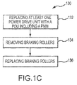
- Figure 1C illustrates a method of retrofitting 130 a powered transport cargo system including braking rollers, according to various embodiments.
- the method 130 comprises replacing at least one power drive unit 132 with a PDU including a PMM.
- the method 130 further comprises removing at least some of the braking rollers 134.
- the method further comprises replacing a portion or all of the braking rollers 136 with transport rollers and/or cargo restraint devices.
- PMM 200 is designed to have a cogging torque sufficient to effectuate first braking function 110 or the static restraint braking function in static state 112.
- static state 112 PMM 200, and wheel component 103, are generally stationary, which may be the case, for example, when power has been removed (e.g. in a power failure and/or manual loading operations, or when the system is not being used).
- first braking function 110 may be required to prevent a stationary or nearly stationary container positioned upon rollers 106 of the tray 104 from moving. For example, a container may start sliding due to tilting of the cargo platform, an undone restraint, etc.
- first braking function 110 is useful in a power off state caused by, for example, power failure and/or manual loading operations, according to various embodiments. Accordingly, the PDU 100 will hold a container starting to move in place.
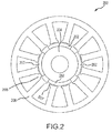
- FIG. 2 is a cross section of a PMM 200 in accordance with various embodiments, generally comprising a magnet component 202, a rotor 204, and a stator component 206.
- PMM 200 is designed to have a high cogging torque (i.e at least 16 ounce inches (113Nm)).
- Cogging torque of electrical motors is the torque due to the interaction between the permanent magnets of the rotor and the stator slots of a PMM.
- cogging torque is an undesirable component for the operation of a PMM. It is especially prominent at lower speeds, and is associated with jerkiness.
- Cogging torque results in torque as well as speed ripple; however, as at high speed the motor moment of inertia filters out the effect of cogging torque, while maintaining a functional motor output torque.
- PMM 200 has a cogging torque of at least 16 ounce inches (113Nm), and a motor output torque of at least 76 ounce inches (536Nm).
- the desired parameters are achieved by adjusting the machine inductance as a function of rotor angle.
- the magnet pole arc (arc length of the magnetic pole) of magnet component 202 may be adjusted to meet these parameters.
- magnet component 202 may be designed with a magnet pole arc of about between 120 and 160 electrical degrees, and, in various embodiments, about 140 electrical degrees.
- the effective cogging resistance which is the resistance produced at wheel component 103 by the cogging torque multiplied by the gear ratio from the wheel component 103 to PMM 200.
- the effective cogging resistance can thus be adjusted based on the desired resistance, which may be determined by the angle of the aircraft.
- PMM 200 may be adjusted for achieving desired cogging torque and motor output values such as the number of magnetic poles, the number of stator teeth, rotor angle, etc.
- PMM 200 In addition to the first braking function 110, PMM 200 also acts as a regenerative brake in order to effectuate second braking function 116 (dynamic control braking) in dynamic state 114.
- second braking function 116 is triggered in response to 1) PDU 100 switching from a power on state 300 (see Figure 3A ) to a power off state 302 (see Figure 4B); and 2 ) the first braking function 110 provided by the motor cogging torque being overridden (e.g. by an operator providing manual force to move a container, a sudden loss of power while a container is in motion and/or tilting of cargo system platform 105, etc.).
- the triggering regenerative brake functionality occurs in response to the power supply being cut from the system (indicated by the open circuit at "S2" in Figure 3C ), and the simultaneous closing of "S1" reverses power flow (motor regeneration) from PDU 100 for activating second braking function 116.
- the reaction force of second braking function 116 is tailored by adjusting the resistance load 400 applied at the terminals of PMM 200 to react based on the specific commands of cargo handling system 102.
- the reaction force 401 of second braking function 116 may be tailored to provide a linear increasing force 402 which increases linearly with container velocity, or a non-linear increasing force 404, and may preferably take into account factors such as maximum transport speed, tilt of cargo system platform 105, container weight, etc. to provide sufficient restraint for a run away container, according to various embodiments.
- Such resistance force may be between about 40 pounds (18.1 kg) and 65 pounds (29.4), depending on system requirements.
- the resistance can be tailored through the gear train of wheel component 103 to generate a fixed value at the drive wheels for a specific speed value of the motor (i.e. speed of motor overridden by a moving container).
- references to "various embodiments”, “one embodiment”, “an embodiment”, “an example embodiment”, etc. indicate that the embodiment described may include a particular feature, structure, or characteristic, but every embodiment may not necessarily include the particular feature, structure, or characteristic. Moreover, such phrases are not necessarily referring to the same embodiment. Further, when a particular feature, structure, or characteristic is described in connection with an embodiment, it is submitted that it is within the knowledge of one skilled in the art to affect such feature, structure, or characteristic in connection with other embodiments whether or not explicitly described. After reading the description, it will be apparent to one skilled in the relevant art(s) how to implement the disclosure in alternative embodiments.
Landscapes
- Engineering & Computer Science (AREA)
- Power Engineering (AREA)
- Mechanical Engineering (AREA)
- Aviation & Aerospace Engineering (AREA)
- Manufacturing & Machinery (AREA)
- Dynamo-Electric Clutches, Dynamo-Electric Brakes (AREA)
- Handcart (AREA)
- Arrangement Or Mounting Of Propulsion Units For Vehicles (AREA)
- Linear Motors (AREA)
Applications Claiming Priority (1)
| Application Number | Priority Date | Filing Date | Title |
|---|---|---|---|
| US14/801,596 US9694978B2 (en) | 2015-07-16 | 2015-07-16 | Cargo handling system |
Publications (2)
| Publication Number | Publication Date |
|---|---|
| EP3135584A1 true EP3135584A1 (de) | 2017-03-01 |
| EP3135584B1 EP3135584B1 (de) | 2020-09-02 |
Family
ID=56686636
Family Applications (1)
| Application Number | Title | Priority Date | Filing Date |
|---|---|---|---|
| EP16179969.7A Active EP3135584B1 (de) | 2015-07-16 | 2016-07-18 | Frachtumschlagsystem |
Country Status (3)
| Country | Link |
|---|---|
| US (2) | US9694978B2 (de) |
| EP (1) | EP3135584B1 (de) |
| CN (1) | CN106347922B (de) |
Families Citing this family (17)
| Publication number | Priority date | Publication date | Assignee | Title |
|---|---|---|---|---|
| US9694978B2 (en) | 2015-07-16 | 2017-07-04 | Goodrich Corporation | Cargo handling system |
| US10604228B2 (en) * | 2017-07-05 | 2020-03-31 | Goodrich Corporation | Cargo handling system |
| CN109347376A (zh) * | 2018-11-09 | 2019-02-15 | 中国科学院长春光学精密机械与物理研究所 | 无刷直流电机制动方法及系统 |
| US10432127B1 (en) * | 2018-11-15 | 2019-10-01 | Goodrich Corporation | Method of dissipating regenerative energy in cargo handling systems |
| US11014672B2 (en) * | 2018-11-15 | 2021-05-25 | Goodrich Corporation | Aircraft cargo handling system architecture |
| CN109533342B (zh) * | 2018-12-07 | 2022-03-04 | 河北汉光重工有限责任公司 | 一种航空运输托盘的连接装置 |
| US11787383B2 (en) | 2019-08-02 | 2023-10-17 | Textron Systems Corporation | Utilizing a multi-track cargo handling assembly on an amphibious air-cushion vehicle |
| JP7585326B2 (ja) | 2019-08-02 | 2024-11-18 | テクストロン イノベーションズ インコーポレイテッド | デュアルレール貨物システムを備えた水陸両用エアクッションビークル |
| US11261029B2 (en) | 2019-08-05 | 2022-03-01 | Goodrich Corporation | Cyclic-force brake caster assembly |
| US10995808B1 (en) | 2019-12-17 | 2021-05-04 | Goodrich Corporation | Solenoid/magnetic hold brake with power off magnet hold function |
| US11124364B1 (en) | 2020-03-13 | 2021-09-21 | Goodrich Corporation | Energy harvesting brake system |
| US20220073292A1 (en) * | 2020-09-04 | 2022-03-10 | Goodrich Corporation | Efficient braking and anti-tail tip cargo handling systems |
| US12139355B2 (en) * | 2020-09-30 | 2024-11-12 | Goodrich Corporation | Variable braking systems and devices |
| US11858660B2 (en) * | 2021-01-05 | 2024-01-02 | Goodrich Corporation | Translating drive devices, systems and methods for cargo handling system |
| CN113232467B (zh) * | 2021-05-17 | 2022-05-24 | 国能朔黄铁路发展有限责任公司 | 车钩装卸辅助设备 |
| US12415602B2 (en) * | 2022-08-12 | 2025-09-16 | Goodrich Corporation | Solenoid/magnetic hold brake with power off magnet hold function |
| US20250026571A1 (en) * | 2023-07-19 | 2025-01-23 | Intelligrated Headquarters, Llc | Energy reuse systems and methods |
Citations (2)
| Publication number | Priority date | Publication date | Assignee | Title |
|---|---|---|---|---|
| EP1371582A2 (de) * | 2002-05-29 | 2003-12-17 | Goodrich Corporation | Antriebseinheit für Frachtfördersysteme |
| WO2004107531A2 (de) * | 2003-05-30 | 2004-12-09 | Siemens Aktiengesellschaft | Rollen und rollenmotoren |
Family Cites Families (14)
| Publication number | Priority date | Publication date | Assignee | Title |
|---|---|---|---|---|
| US3902583A (en) * | 1970-09-21 | 1975-09-02 | Jerry Laibson | Load bearing tray |
| US4780043A (en) | 1986-10-09 | 1988-10-25 | The Boeing Company | Modular cargo loading and unloading system |
| US5183150A (en) | 1991-12-13 | 1993-02-02 | Allied-Signal Inc. | Cargo drive unit with a hysteresis coupling |
| DE59807512D1 (de) * | 1997-05-28 | 2003-04-24 | Telair Int Gmbh | Einbauvorrichtung für eine Rollenantriebseinheit |
| US6148967A (en) | 1998-07-10 | 2000-11-21 | Alliedsignal Inc. | Non-contacting and torquer brake mechanism |
| JP3489022B2 (ja) * | 1999-03-18 | 2004-01-19 | 株式会社安川電機 | ダイナミックブレーキ回路と半導体インバータ装置 |
| EG22932A (en) * | 2000-05-31 | 2002-01-13 | Shell Int Research | Method and system for reducing longitudinal fluid flow around a permeable well tubular |
| CA2442072C (en) | 2001-03-29 | 2008-02-12 | Ancra International Llc | Cargo power drive unit |
| EP1620312B1 (de) | 2003-05-02 | 2007-09-19 | Ancra International, Llc | Lenkbare /einziehbare frachtkraftantriebseinheit |
| DE102006051337A1 (de) * | 2006-10-31 | 2008-05-08 | Knorr-Bremse Systeme für Schienenfahrzeuge GmbH | Traktionsantrieb eines Schienenfahrzeugs zum Antreiben und zum generatorischen Bremsen |
| DE102009035894A1 (de) | 2009-08-03 | 2011-02-10 | Wittenstein Ag | Maschine zum Festlegen |
| JP5578154B2 (ja) | 2011-10-25 | 2014-08-27 | アイシン精機株式会社 | 車両用ドア開閉装置 |
| EP3018818A1 (de) * | 2014-11-10 | 2016-05-11 | Ancra International LLC | Kraftantriebseinheit mit dynamischer abschaltbremse |
| US9694978B2 (en) | 2015-07-16 | 2017-07-04 | Goodrich Corporation | Cargo handling system |
-
2015
- 2015-07-16 US US14/801,596 patent/US9694978B2/en active Active
-
2016
- 2016-07-15 CN CN201610557312.1A patent/CN106347922B/zh active Active
- 2016-07-18 EP EP16179969.7A patent/EP3135584B1/de active Active
-
2017
- 2017-06-29 US US15/637,141 patent/US10023387B2/en active Active
Patent Citations (2)
| Publication number | Priority date | Publication date | Assignee | Title |
|---|---|---|---|---|
| EP1371582A2 (de) * | 2002-05-29 | 2003-12-17 | Goodrich Corporation | Antriebseinheit für Frachtfördersysteme |
| WO2004107531A2 (de) * | 2003-05-30 | 2004-12-09 | Siemens Aktiengesellschaft | Rollen und rollenmotoren |
Also Published As
| Publication number | Publication date |
|---|---|
| CN106347922A (zh) | 2017-01-25 |
| CN106347922B (zh) | 2020-03-03 |
| US10023387B2 (en) | 2018-07-17 |
| US9694978B2 (en) | 2017-07-04 |
| US20170015503A1 (en) | 2017-01-19 |
| US20170297821A1 (en) | 2017-10-19 |
| EP3135584B1 (de) | 2020-09-02 |
Similar Documents
| Publication | Publication Date | Title |
|---|---|---|
| US10023387B2 (en) | Cargo handling system | |
| US10502277B2 (en) | Electric brake device with parking function | |
| US9889990B2 (en) | Power drive unit with power-off dynamic brake | |
| US9205923B1 (en) | Manual override cargo unloading system for air cushion supported aircraft cargo loading robot | |
| US20160178021A1 (en) | Electric brake device | |
| CN110999047A (zh) | 用于驱动推进机构的冗余的电机 | |
| US11060576B2 (en) | Electric linear motion actuator | |
| EP3147167A1 (de) | Elektrische bremsvorrichtung | |
| EP3838756B1 (de) | Solenoid-/magnethaltebremse mit abschaltmagnethaltefunktion | |
| EP3297135B1 (de) | Dynamo/motor mit eingebautem drehzahlwandler | |
| EP3747803B1 (de) | Elektromotorantriebseinheit für ein flugzeugladeraumfussbodensystem | |
| US20190356206A1 (en) | Dual axis motor | |
| US10944309B2 (en) | Electric motor device | |
| CN111792024A (zh) | 可配置为占用正常模式或rto模式的飞行器机轮制动系统 | |
| US10059433B2 (en) | Rotation-blocking device with simplified structure, and actuator comprising such a device | |
| WO2006049778A1 (en) | Cargo system roller/lock/power drive unit tray integration | |
| EP1870985B1 (de) | Ein verbesserter bürstenloser Motor mit selbstbremsenden Merkmalen | |
| US7456594B2 (en) | Electric motor brake engagement holdup system | |
| EP3168151B1 (de) | Hebe- und haltedifferentialaufzugs-pdu mit einem permanentmagnetrotor | |
| US11545872B2 (en) | Motor with brake | |
| EP4321432A1 (de) | Elektromagnetische haltebremse mit haltefunktion für einen ausschaltmagneten | |
| EP4289779A1 (de) | Verfahren zum prüfen des betriebs einer rettungswinde der nächsten generation | |
| CN111277111A (zh) | 直线电机结构 | |
| JP2015145158A (ja) | 電動ブレーキ装置 | |
| JPH09308200A (ja) | 永久磁石式回転電機 |
Legal Events
| Date | Code | Title | Description |
|---|---|---|---|
| PUAI | Public reference made under article 153(3) epc to a published international application that has entered the european phase |
Free format text: ORIGINAL CODE: 0009012 |
|
| STAA | Information on the status of an ep patent application or granted ep patent |
Free format text: STATUS: THE APPLICATION HAS BEEN PUBLISHED |
|
| AK | Designated contracting states |
Kind code of ref document: A1 Designated state(s): AL AT BE BG CH CY CZ DE DK EE ES FI FR GB GR HR HU IE IS IT LI LT LU LV MC MK MT NL NO PL PT RO RS SE SI SK SM TR |
|
| AX | Request for extension of the european patent |
Extension state: BA ME |
|
| STAA | Information on the status of an ep patent application or granted ep patent |
Free format text: STATUS: REQUEST FOR EXAMINATION WAS MADE |
|
| 17P | Request for examination filed |
Effective date: 20170831 |
|
| RBV | Designated contracting states (corrected) |
Designated state(s): AL AT BE BG CH CY CZ DE DK EE ES FI FR GB GR HR HU IE IS IT LI LT LU LV MC MK MT NL NO PL PT RO RS SE SI SK SM TR |
|
| STAA | Information on the status of an ep patent application or granted ep patent |
Free format text: STATUS: EXAMINATION IS IN PROGRESS |
|
| 17Q | First examination report despatched |
Effective date: 20190411 |
|
| GRAP | Despatch of communication of intention to grant a patent |
Free format text: ORIGINAL CODE: EPIDOSNIGR1 |
|
| STAA | Information on the status of an ep patent application or granted ep patent |
Free format text: STATUS: GRANT OF PATENT IS INTENDED |
|
| INTG | Intention to grant announced |
Effective date: 20200326 |
|
| RIN1 | Information on inventor provided before grant (corrected) |
Inventor name: LARSON, WALACE HAROLD Inventor name: HARMS, SCOTT |
|
| GRAS | Grant fee paid |
Free format text: ORIGINAL CODE: EPIDOSNIGR3 |
|
| GRAA | (expected) grant |
Free format text: ORIGINAL CODE: 0009210 |
|
| STAA | Information on the status of an ep patent application or granted ep patent |
Free format text: STATUS: THE PATENT HAS BEEN GRANTED |
|
| AK | Designated contracting states |
Kind code of ref document: B1 Designated state(s): AL AT BE BG CH CY CZ DE DK EE ES FI FR GB GR HR HU IE IS IT LI LT LU LV MC MK MT NL NO PL PT RO RS SE SI SK SM TR |
|
| REG | Reference to a national code |
Ref country code: GB Ref legal event code: FG4D |
|
| REG | Reference to a national code |
Ref country code: AT Ref legal event code: REF Ref document number: 1308539 Country of ref document: AT Kind code of ref document: T Effective date: 20200915 Ref country code: CH Ref legal event code: EP |
|
| REG | Reference to a national code |
Ref country code: DE Ref legal event code: R096 Ref document number: 602016043067 Country of ref document: DE |
|
| REG | Reference to a national code |
Ref country code: IE Ref legal event code: FG4D |
|
| REG | Reference to a national code |
Ref country code: LT Ref legal event code: MG4D |
|
| PG25 | Lapsed in a contracting state [announced via postgrant information from national office to epo] |
Ref country code: LT Free format text: LAPSE BECAUSE OF FAILURE TO SUBMIT A TRANSLATION OF THE DESCRIPTION OR TO PAY THE FEE WITHIN THE PRESCRIBED TIME-LIMIT Effective date: 20200902 Ref country code: FI Free format text: LAPSE BECAUSE OF FAILURE TO SUBMIT A TRANSLATION OF THE DESCRIPTION OR TO PAY THE FEE WITHIN THE PRESCRIBED TIME-LIMIT Effective date: 20200902 Ref country code: SE Free format text: LAPSE BECAUSE OF FAILURE TO SUBMIT A TRANSLATION OF THE DESCRIPTION OR TO PAY THE FEE WITHIN THE PRESCRIBED TIME-LIMIT Effective date: 20200902 Ref country code: HR Free format text: LAPSE BECAUSE OF FAILURE TO SUBMIT A TRANSLATION OF THE DESCRIPTION OR TO PAY THE FEE WITHIN THE PRESCRIBED TIME-LIMIT Effective date: 20200902 Ref country code: BG Free format text: LAPSE BECAUSE OF FAILURE TO SUBMIT A TRANSLATION OF THE DESCRIPTION OR TO PAY THE FEE WITHIN THE PRESCRIBED TIME-LIMIT Effective date: 20201202 Ref country code: GR Free format text: LAPSE BECAUSE OF FAILURE TO SUBMIT A TRANSLATION OF THE DESCRIPTION OR TO PAY THE FEE WITHIN THE PRESCRIBED TIME-LIMIT Effective date: 20201203 Ref country code: NO Free format text: LAPSE BECAUSE OF FAILURE TO SUBMIT A TRANSLATION OF THE DESCRIPTION OR TO PAY THE FEE WITHIN THE PRESCRIBED TIME-LIMIT Effective date: 20201202 |
|
| REG | Reference to a national code |
Ref country code: NL Ref legal event code: MP Effective date: 20200902 |
|
| REG | Reference to a national code |
Ref country code: AT Ref legal event code: MK05 Ref document number: 1308539 Country of ref document: AT Kind code of ref document: T Effective date: 20200902 |
|
| PG25 | Lapsed in a contracting state [announced via postgrant information from national office to epo] |
Ref country code: RS Free format text: LAPSE BECAUSE OF FAILURE TO SUBMIT A TRANSLATION OF THE DESCRIPTION OR TO PAY THE FEE WITHIN THE PRESCRIBED TIME-LIMIT Effective date: 20200902 Ref country code: PL Free format text: LAPSE BECAUSE OF FAILURE TO SUBMIT A TRANSLATION OF THE DESCRIPTION OR TO PAY THE FEE WITHIN THE PRESCRIBED TIME-LIMIT Effective date: 20200902 Ref country code: LV Free format text: LAPSE BECAUSE OF FAILURE TO SUBMIT A TRANSLATION OF THE DESCRIPTION OR TO PAY THE FEE WITHIN THE PRESCRIBED TIME-LIMIT Effective date: 20200902 |
|
| PG25 | Lapsed in a contracting state [announced via postgrant information from national office to epo] |
Ref country code: CZ Free format text: LAPSE BECAUSE OF FAILURE TO SUBMIT A TRANSLATION OF THE DESCRIPTION OR TO PAY THE FEE WITHIN THE PRESCRIBED TIME-LIMIT Effective date: 20200902 Ref country code: PT Free format text: LAPSE BECAUSE OF FAILURE TO SUBMIT A TRANSLATION OF THE DESCRIPTION OR TO PAY THE FEE WITHIN THE PRESCRIBED TIME-LIMIT Effective date: 20210104 Ref country code: RO Free format text: LAPSE BECAUSE OF FAILURE TO SUBMIT A TRANSLATION OF THE DESCRIPTION OR TO PAY THE FEE WITHIN THE PRESCRIBED TIME-LIMIT Effective date: 20200902 Ref country code: SM Free format text: LAPSE BECAUSE OF FAILURE TO SUBMIT A TRANSLATION OF THE DESCRIPTION OR TO PAY THE FEE WITHIN THE PRESCRIBED TIME-LIMIT Effective date: 20200902 Ref country code: NL Free format text: LAPSE BECAUSE OF FAILURE TO SUBMIT A TRANSLATION OF THE DESCRIPTION OR TO PAY THE FEE WITHIN THE PRESCRIBED TIME-LIMIT Effective date: 20200902 Ref country code: EE Free format text: LAPSE BECAUSE OF FAILURE TO SUBMIT A TRANSLATION OF THE DESCRIPTION OR TO PAY THE FEE WITHIN THE PRESCRIBED TIME-LIMIT Effective date: 20200902 |
|
| PG25 | Lapsed in a contracting state [announced via postgrant information from national office to epo] |
Ref country code: AT Free format text: LAPSE BECAUSE OF FAILURE TO SUBMIT A TRANSLATION OF THE DESCRIPTION OR TO PAY THE FEE WITHIN THE PRESCRIBED TIME-LIMIT Effective date: 20200902 Ref country code: AL Free format text: LAPSE BECAUSE OF FAILURE TO SUBMIT A TRANSLATION OF THE DESCRIPTION OR TO PAY THE FEE WITHIN THE PRESCRIBED TIME-LIMIT Effective date: 20200902 Ref country code: ES Free format text: LAPSE BECAUSE OF FAILURE TO SUBMIT A TRANSLATION OF THE DESCRIPTION OR TO PAY THE FEE WITHIN THE PRESCRIBED TIME-LIMIT Effective date: 20200902 Ref country code: IS Free format text: LAPSE BECAUSE OF FAILURE TO SUBMIT A TRANSLATION OF THE DESCRIPTION OR TO PAY THE FEE WITHIN THE PRESCRIBED TIME-LIMIT Effective date: 20210102 |
|
| REG | Reference to a national code |
Ref country code: DE Ref legal event code: R097 Ref document number: 602016043067 Country of ref document: DE |
|
| PG25 | Lapsed in a contracting state [announced via postgrant information from national office to epo] |
Ref country code: SK Free format text: LAPSE BECAUSE OF FAILURE TO SUBMIT A TRANSLATION OF THE DESCRIPTION OR TO PAY THE FEE WITHIN THE PRESCRIBED TIME-LIMIT Effective date: 20200902 |
|
| PLBE | No opposition filed within time limit |
Free format text: ORIGINAL CODE: 0009261 |
|
| STAA | Information on the status of an ep patent application or granted ep patent |
Free format text: STATUS: NO OPPOSITION FILED WITHIN TIME LIMIT |
|
| 26N | No opposition filed |
Effective date: 20210603 |
|
| PG25 | Lapsed in a contracting state [announced via postgrant information from national office to epo] |
Ref country code: DK Free format text: LAPSE BECAUSE OF FAILURE TO SUBMIT A TRANSLATION OF THE DESCRIPTION OR TO PAY THE FEE WITHIN THE PRESCRIBED TIME-LIMIT Effective date: 20200902 Ref country code: SI Free format text: LAPSE BECAUSE OF FAILURE TO SUBMIT A TRANSLATION OF THE DESCRIPTION OR TO PAY THE FEE WITHIN THE PRESCRIBED TIME-LIMIT Effective date: 20200902 |
|
| PG25 | Lapsed in a contracting state [announced via postgrant information from national office to epo] |
Ref country code: IT Free format text: LAPSE BECAUSE OF FAILURE TO SUBMIT A TRANSLATION OF THE DESCRIPTION OR TO PAY THE FEE WITHIN THE PRESCRIBED TIME-LIMIT Effective date: 20200902 |
|
| REG | Reference to a national code |
Ref country code: CH Ref legal event code: PL |
|
| GBPC | Gb: european patent ceased through non-payment of renewal fee |
Effective date: 20210718 |
|
| PG25 | Lapsed in a contracting state [announced via postgrant information from national office to epo] |
Ref country code: MC Free format text: LAPSE BECAUSE OF FAILURE TO SUBMIT A TRANSLATION OF THE DESCRIPTION OR TO PAY THE FEE WITHIN THE PRESCRIBED TIME-LIMIT Effective date: 20200902 |
|
| REG | Reference to a national code |
Ref country code: BE Ref legal event code: MM Effective date: 20210731 |
|
| PG25 | Lapsed in a contracting state [announced via postgrant information from national office to epo] |
Ref country code: LI Free format text: LAPSE BECAUSE OF NON-PAYMENT OF DUE FEES Effective date: 20210731 Ref country code: GB Free format text: LAPSE BECAUSE OF NON-PAYMENT OF DUE FEES Effective date: 20210718 Ref country code: CH Free format text: LAPSE BECAUSE OF NON-PAYMENT OF DUE FEES Effective date: 20210731 |
|
| PG25 | Lapsed in a contracting state [announced via postgrant information from national office to epo] |
Ref country code: LU Free format text: LAPSE BECAUSE OF NON-PAYMENT OF DUE FEES Effective date: 20210718 |
|
| REG | Reference to a national code |
Ref country code: FR Ref legal event code: PLFP Year of fee payment: 7 |
|
| PG25 | Lapsed in a contracting state [announced via postgrant information from national office to epo] |
Ref country code: IE Free format text: LAPSE BECAUSE OF NON-PAYMENT OF DUE FEES Effective date: 20210718 Ref country code: BE Free format text: LAPSE BECAUSE OF NON-PAYMENT OF DUE FEES Effective date: 20210731 |
|
| PG25 | Lapsed in a contracting state [announced via postgrant information from national office to epo] |
Ref country code: HU Free format text: LAPSE BECAUSE OF FAILURE TO SUBMIT A TRANSLATION OF THE DESCRIPTION OR TO PAY THE FEE WITHIN THE PRESCRIBED TIME-LIMIT; INVALID AB INITIO Effective date: 20160718 |
|
| P01 | Opt-out of the competence of the unified patent court (upc) registered |
Effective date: 20230522 |
|
| PG25 | Lapsed in a contracting state [announced via postgrant information from national office to epo] |
Ref country code: CY Free format text: LAPSE BECAUSE OF FAILURE TO SUBMIT A TRANSLATION OF THE DESCRIPTION OR TO PAY THE FEE WITHIN THE PRESCRIBED TIME-LIMIT Effective date: 20200902 |
|
| PG25 | Lapsed in a contracting state [announced via postgrant information from national office to epo] |
Ref country code: MK Free format text: LAPSE BECAUSE OF FAILURE TO SUBMIT A TRANSLATION OF THE DESCRIPTION OR TO PAY THE FEE WITHIN THE PRESCRIBED TIME-LIMIT Effective date: 20200902 |
|
| PG25 | Lapsed in a contracting state [announced via postgrant information from national office to epo] |
Ref country code: TR Free format text: LAPSE BECAUSE OF FAILURE TO SUBMIT A TRANSLATION OF THE DESCRIPTION OR TO PAY THE FEE WITHIN THE PRESCRIBED TIME-LIMIT Effective date: 20200902 |
|
| PG25 | Lapsed in a contracting state [announced via postgrant information from national office to epo] |
Ref country code: MT Free format text: LAPSE BECAUSE OF FAILURE TO SUBMIT A TRANSLATION OF THE DESCRIPTION OR TO PAY THE FEE WITHIN THE PRESCRIBED TIME-LIMIT Effective date: 20200902 |
|
| PGFP | Annual fee paid to national office [announced via postgrant information from national office to epo] |
Ref country code: FR Payment date: 20250619 Year of fee payment: 10 |
|
| PGFP | Annual fee paid to national office [announced via postgrant information from national office to epo] |
Ref country code: DE Payment date: 20250620 Year of fee payment: 10 |