EP3136541A1 - Erregungsschaltkreis einer lichtmaschine eines kraftfahrzeugs, spannungsregler und diesen umfassende lichtmaschine - Google Patents
Erregungsschaltkreis einer lichtmaschine eines kraftfahrzeugs, spannungsregler und diesen umfassende lichtmaschine Download PDFInfo
- Publication number
- EP3136541A1 EP3136541A1 EP16180578.3A EP16180578A EP3136541A1 EP 3136541 A1 EP3136541 A1 EP 3136541A1 EP 16180578 A EP16180578 A EP 16180578A EP 3136541 A1 EP3136541 A1 EP 3136541A1
- Authority
- EP
- European Patent Office
- Prior art keywords
- excitation
- circuit
- motor vehicle
- voltage
- terminal
- Prior art date
- Legal status (The legal status is an assumption and is not a legal conclusion. Google has not performed a legal analysis and makes no representation as to the accuracy of the status listed.)
- Withdrawn
Links
Images


Classifications
-
- H—ELECTRICITY
- H02—GENERATION; CONVERSION OR DISTRIBUTION OF ELECTRIC POWER
- H02P—CONTROL OR REGULATION OF ELECTRIC MOTORS, ELECTRIC GENERATORS OR DYNAMO-ELECTRIC CONVERTERS; CONTROLLING TRANSFORMERS, REACTORS OR CHOKE COILS
- H02P9/00—Arrangements for controlling electric generators for the purpose of obtaining a desired output
- H02P9/14—Arrangements for controlling electric generators for the purpose of obtaining a desired output by variation of field
- H02P9/26—Arrangements for controlling electric generators for the purpose of obtaining a desired output by variation of field using discharge tubes or semiconductor devices
- H02P9/30—Arrangements for controlling electric generators for the purpose of obtaining a desired output by variation of field using discharge tubes or semiconductor devices using semiconductor devices
- H02P9/305—Arrangements for controlling electric generators for the purpose of obtaining a desired output by variation of field using discharge tubes or semiconductor devices using semiconductor devices controlling voltage
-
- B—PERFORMING OPERATIONS; TRANSPORTING
- B60—VEHICLES IN GENERAL
- B60L—PROPULSION OF ELECTRICALLY-PROPELLED VEHICLES; SUPPLYING ELECTRIC POWER FOR AUXILIARY EQUIPMENT OF ELECTRICALLY-PROPELLED VEHICLES; ELECTRODYNAMIC BRAKE SYSTEMS FOR VEHICLES IN GENERAL; MAGNETIC SUSPENSION OR LEVITATION FOR VEHICLES; MONITORING OPERATING VARIABLES OF ELECTRICALLY-PROPELLED VEHICLES; ELECTRIC SAFETY DEVICES FOR ELECTRICALLY-PROPELLED VEHICLES
- B60L1/00—Supplying electric power to auxiliary equipment of vehicles
-
- H—ELECTRICITY
- H02—GENERATION; CONVERSION OR DISTRIBUTION OF ELECTRIC POWER
- H02J—ELECTRIC POWER NETWORKS; CIRCUIT ARRANGEMENTS OR SYSTEMS FOR SUPPLYING OR DISTRIBUTING ELECTRIC POWER; SYSTEMS FOR STORING ELECTRIC ENERGY
- H02J7/00—Circuit arrangements for charging or discharging batteries or for supplying loads from batteries
- H02J7/14—Circuit arrangements for charging or discharging batteries or for supplying loads from batteries for charging batteries from dynamo-electric generators driven at varying speed, e.g. on vehicle
- H02J7/16—Regulation of the charging current or voltage by variation of field
-
- H—ELECTRICITY
- H02—GENERATION; CONVERSION OR DISTRIBUTION OF ELECTRIC POWER
- H02J—ELECTRIC POWER NETWORKS; CIRCUIT ARRANGEMENTS OR SYSTEMS FOR SUPPLYING OR DISTRIBUTING ELECTRIC POWER; SYSTEMS FOR STORING ELECTRIC ENERGY
- H02J7/00—Circuit arrangements for charging or discharging batteries or for supplying loads from batteries
- H02J7/14—Circuit arrangements for charging or discharging batteries or for supplying loads from batteries for charging batteries from dynamo-electric generators driven at varying speed, e.g. on vehicle
- H02J7/16—Regulation of the charging current or voltage by variation of field
- H02J7/24—Regulation of the charging current or voltage by variation of field using discharge tubes or semiconductor devices
-
- H—ELECTRICITY
- H02—GENERATION; CONVERSION OR DISTRIBUTION OF ELECTRIC POWER
- H02P—CONTROL OR REGULATION OF ELECTRIC MOTORS, ELECTRIC GENERATORS OR DYNAMO-ELECTRIC CONVERTERS; CONTROLLING TRANSFORMERS, REACTORS OR CHOKE COILS
- H02P9/00—Arrangements for controlling electric generators for the purpose of obtaining a desired output
- H02P9/48—Arrangements for obtaining a constant output value at varying speed of the generator, e.g. on vehicle
-
- H—ELECTRICITY
- H03—ELECTRONIC CIRCUITRY
- H03K—PULSE TECHNIQUE
- H03K17/00—Electronic switching or gating, i.e. not by contact-making and –breaking
- H03K17/51—Electronic switching or gating, i.e. not by contact-making and –breaking characterised by the components used
- H03K17/56—Electronic switching or gating, i.e. not by contact-making and –breaking characterised by the components used by the use, as active elements, of semiconductor devices
- H03K17/687—Electronic switching or gating, i.e. not by contact-making and –breaking characterised by the components used by the use, as active elements, of semiconductor devices the devices being field-effect transistors
-
- H—ELECTRICITY
- H02—GENERATION; CONVERSION OR DISTRIBUTION OF ELECTRIC POWER
- H02P—CONTROL OR REGULATION OF ELECTRIC MOTORS, ELECTRIC GENERATORS OR DYNAMO-ELECTRIC CONVERTERS; CONTROLLING TRANSFORMERS, REACTORS OR CHOKE COILS
- H02P2101/00—Special adaptation of control arrangements for generators
- H02P2101/45—Special adaptation of control arrangements for generators for motor vehicles, e.g. car alternators
Definitions
- the present invention relates to an excitation circuit of a motor vehicle alternator, as well as the voltage regulator and the alternator comprising this excitation circuit.
- a voltage of the onboard network is regulated by controlling a magnetic flux intensity, resulting from an excitation winding of a rotor, passing through the windings of a stator.
- This function is provided by an excitation circuit which adjusts a value of an excitation current of the rotor as a function of the load variations and rotational speed of the alternator.
- an electronic power stage of this circuit is controlled by switching at a fixed or variable frequency.
- a voltage across the excitation winding is taken to the battery potential for a given time, and then released until the end of the excitation period.
- a mean value of an excitation current is proportional to the ratio of a high time to a period of an excitation signal. This duty cycle is determined by a regulation loop of a regulator.
- the current in the rotor winding can not be interrupted instantaneously.
- the electronic power stage must provide a conduction path to allow the rotor current to flow freely. This function is traditionally performed by a diode called “freewheel” placed in parallel on the excitation winding and which is activated naturally when the voltage across the rotor becomes negative.
- a first "high side" switching element is a first power transistor, generally of the NMOS type.
- the freewheeling diode is realized by exploiting the base-emitter diode of a bipolar transistor.
- the disadvantage of the diode is to generate losses Vf * If * Do.
- Intrinsic diodes generally have lower performance than bipolar diodes.
- a control circuit must send control signals of the first gate voltage and a second gate voltage of the second non-overlapping transistor.
- the control circuit must therefore manage dead times between activations of the transistors.
- Such a control circuit also has the disadvantage of having a mode common between the controls of the high-side and low-side power transistors, in particular during EMC tests, which can make it difficult to use in the automotive world.
- the present invention therefore aims to overcome these disadvantages.
- It relates specifically to an excitation circuit of a motor vehicle alternator of the type capable of controlling an excitation current in an excitation winding of this alternator as a function of a control of a control loop. a voltage of an on-board network of the vehicle powered by a battery to which this alternator is connected.
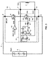
- this excitation circuit of a motor vehicle alternator further comprises a servocontrol loop of a drain-source voltage of the second power transistor.
- the correction device is, according to the invention, of the "integral proportional" type.
- the second control circuit is an operational amplifier comprising a feedback loop constituted by a first resistor and a capacitor in series.
- the device for generating a reference voltage consists of a current generator connected to an inverting input of the operational amplifier.
- the return device is constituted by this operational amplifier, the inverting input being connected by a second resistor to the first excitation terminal, and a non-inverting input of this operational amplifier being connected to the second excitation terminal.
- the device for generating a reference voltage is connected between a non-inverting input of the operational amplifier and the second excitation terminal.
- the invention also relates to a vehicle voltage regulator which comprises an excitation circuit having the above characteristics.
- An alternator of a motor vehicle comprising such a regulator is also covered by the invention.
- a diagram of an excitation circuit 1 of the type concerned by the invention is represented on the Figure 1 .
- This excitation circuit 1 makes it possible to control an excitation current lexc circulating in an excitation winding 2 of the alternator as a function of an EXC_ON command of a regulation loop of a voltage Vbat + of a network of board 3 of the vehicle powered by a battery 4.
- the first and second gate voltages GHS, GLS are driven in phase opposition by the control of the regulation loop EXC_ON by means of the inverter 13.
- this excitation circuit 1 has many disadvantages, in particular in terms of electromagnetic compatibility (EMC).
- the inventive entity proposes to reduce conduction losses of the second power transistor 11 acting as a freewheeling diode by combining a decrease in its equivalent resistance with an independent control of the second gate voltage GLS, without common mode with the control of the first gate voltage GHS of the first power transistor 9.
- the excitation circuit 14 controls the second power transistor 11 so that it has a diode behavior through a feedback loop 15 of a drain-source voltage Vds, which ensures both low losses and independence voltage.
- the breaking current Ifw of the excitation winding 2 of the rotor flows first in the intrinsic diode of the second power transistor 11.
- the voltage at the terminals of this diode increases, then the loop of servocontrol 15 will maintain this voltage close to the reference voltage VREF.
- the breaking current Ifw decreases, the control loop 15 will block this second power transistor 11.
- the enslavement of the drain-source voltage Vds is achieved by the second control circuit 12 which is an operational amplifier 12 comprising a feedback loop constituted by a first resistor 20 in series with a capacitor 21.
- the reference voltage VREF is obtained by means of a current generator 22 connected to an inverting input 23 of the operational amplifier 12.
- the inverting input 23 of the operational amplifier 12 is connected by a second resistor 24 to the first excitation terminal 7, a non-inverting input 25 being connected to the second excitation terminal 8.
- An output 26 of the operational amplifier 12 drives via a third resistor 27 the second gate voltage GLS of the second power transistor 11.
- a proportional integral type (PI) correction is thus used, which makes it possible to adjust the quality of the servocontrol.
- the third resistor 27 placed in series at the output of the operational amplifier 12 makes it possible to adjust the dynamics of the second power transistor 11.
- a reference voltage source VREF substantially equal to 0.1 V can be connected between the non-inverting input 25 of the operational amplifier 12 and the second excitation terminal 8 to adjust an offset voltage of the feedback loop 20, 21.
- the gain in efficiency of the excitation circuit 14 according to the invention is directly related to the ratio between a first threshold voltage Vf of the intrinsic diode of a known excitation circuit, and a second threshold voltage VREF of the diode freewheel equivalent to the second power transistor 11 in the excitation circuit 14 according to the invention.
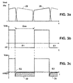
- the Figure 3a are time diagrams of the excitation current lexc (solid line 28) flowing in the first power transistor 9 and the breaking current Ifw (dashed line 29) flowing in the second power transistor 11 when the first power transistor 9 is open.
- La Figure 3c shows that the losses E2 due to the breaking current Ifw during the periods Don of switching are equal to VREF * Ifw * Don, that is to say that the loss reduction is substantially represented by the hatched surface 30.
Landscapes
- Engineering & Computer Science (AREA)
- Power Engineering (AREA)
- Transportation (AREA)
- Mechanical Engineering (AREA)
- Control Of Eletrric Generators (AREA)
Applications Claiming Priority (1)
| Application Number | Priority Date | Filing Date | Title |
|---|---|---|---|
| FR1557988A FR3040558B1 (fr) | 2015-08-28 | 2015-08-28 | Circuit d'excitation d'un alternateur de vehicule automobile, regulateur de tension et alternateur l'incorporant |
Publications (1)
| Publication Number | Publication Date |
|---|---|
| EP3136541A1 true EP3136541A1 (de) | 2017-03-01 |
Family
ID=54937246
Family Applications (1)
| Application Number | Title | Priority Date | Filing Date |
|---|---|---|---|
| EP16180578.3A Withdrawn EP3136541A1 (de) | 2015-08-28 | 2016-07-21 | Erregungsschaltkreis einer lichtmaschine eines kraftfahrzeugs, spannungsregler und diesen umfassende lichtmaschine |
Country Status (4)
| Country | Link |
|---|---|
| US (1) | US9866162B2 (de) |
| EP (1) | EP3136541A1 (de) |
| CN (1) | CN106487295A (de) |
| FR (1) | FR3040558B1 (de) |
Families Citing this family (3)
| Publication number | Priority date | Publication date | Assignee | Title |
|---|---|---|---|---|
| DE102017201690A1 (de) * | 2017-02-02 | 2018-08-02 | Siemens Aktiengesellschaft | Spannungserzeugungsvorrichtung und Verfahren zum Betreiben einer Spannungserzeugungsvorrichtung |
| US10199968B2 (en) * | 2017-05-22 | 2019-02-05 | Infineon Technologies Ag | Fault handling for alternator control devices |
| US10840839B1 (en) * | 2019-10-01 | 2020-11-17 | The Boeing Company | Method and system for independent-speed-variable-frequency-generator-based power system voltage regulation |
Citations (5)
| Publication number | Priority date | Publication date | Assignee | Title |
|---|---|---|---|---|
| FR2733097A1 (fr) | 1995-04-13 | 1996-10-18 | Valeo Equip Electr Moteur | Circuit d'excitation d'alternateur notamment de vehicule automobile, et regulateur et alternateur l'incorporant |
| US20050218964A1 (en) * | 2004-03-31 | 2005-10-06 | Matsushita Electric Industrial Co., Ltd. | Active diode |
| JP2007174788A (ja) * | 2005-12-21 | 2007-07-05 | Denso Corp | 電流検出装置および電流制御装置 |
| EP2637293A1 (de) * | 2012-03-07 | 2013-09-11 | Dialog Semiconductor GmbH | Aktiver Gleichrichter mit Modulation |
| CN103944426A (zh) * | 2014-05-05 | 2014-07-23 | 广州金升阳科技有限公司 | 一种同步整流实现方法 |
Family Cites Families (7)
| Publication number | Priority date | Publication date | Assignee | Title |
|---|---|---|---|---|
| FR2842042A1 (fr) * | 2002-07-04 | 2004-01-09 | Valeo Equip Electr Moteur | Module de controle et de puissance d'un alterno-demarreur integrale |
| FR2896643B1 (fr) * | 2006-01-23 | 2009-01-09 | Valeo Equip Electr Moteur | Dispositif de commande d'un transistor mos |
| JP5206130B2 (ja) * | 2008-06-05 | 2013-06-12 | 三菱電機株式会社 | コイル界磁式同期モーター回生システムおよびその制御方法 |
| CN201294480Y (zh) * | 2008-10-09 | 2009-08-19 | 北京东风机车电器厂 | 一种机车用电压调整器 |
| JP5389609B2 (ja) * | 2009-11-02 | 2014-01-15 | 本田技研工業株式会社 | 自励式発電機の進相負荷保護装置 |
| US8487592B2 (en) * | 2010-02-10 | 2013-07-16 | Infineon Technologies Ag | Circuit and method for de-energizing a field coil |
| FR2971648B1 (fr) * | 2011-02-16 | 2016-10-14 | Moteurs Leroy-Somer | Ensemble fonctionnant a regime variable, comportant un alternateur synchrone a rotor bobine et un convertisseur |
-
2015
- 2015-08-28 FR FR1557988A patent/FR3040558B1/fr not_active Expired - Fee Related
-
2016
- 2016-07-21 EP EP16180578.3A patent/EP3136541A1/de not_active Withdrawn
- 2016-08-26 US US15/248,301 patent/US9866162B2/en not_active Expired - Fee Related
- 2016-08-26 CN CN201610740629.9A patent/CN106487295A/zh active Pending
Patent Citations (5)
| Publication number | Priority date | Publication date | Assignee | Title |
|---|---|---|---|---|
| FR2733097A1 (fr) | 1995-04-13 | 1996-10-18 | Valeo Equip Electr Moteur | Circuit d'excitation d'alternateur notamment de vehicule automobile, et regulateur et alternateur l'incorporant |
| US20050218964A1 (en) * | 2004-03-31 | 2005-10-06 | Matsushita Electric Industrial Co., Ltd. | Active diode |
| JP2007174788A (ja) * | 2005-12-21 | 2007-07-05 | Denso Corp | 電流検出装置および電流制御装置 |
| EP2637293A1 (de) * | 2012-03-07 | 2013-09-11 | Dialog Semiconductor GmbH | Aktiver Gleichrichter mit Modulation |
| CN103944426A (zh) * | 2014-05-05 | 2014-07-23 | 广州金升阳科技有限公司 | 一种同步整流实现方法 |
Also Published As
| Publication number | Publication date |
|---|---|
| FR3040558A1 (fr) | 2017-03-03 |
| US20170063265A1 (en) | 2017-03-02 |
| CN106487295A (zh) | 2017-03-08 |
| FR3040558B1 (fr) | 2017-08-11 |
| US9866162B2 (en) | 2018-01-09 |
Similar Documents
| Publication | Publication Date | Title |
|---|---|---|
| EP3422554B1 (de) | Reversibler ac/dc-wandler mit thyristoren | |
| EP2719070B1 (de) | Verfahren zur steuerung des widerständigen drehmoments eines kraftfahrzeuggenerators und system zur durchführung dieses verfahrens | |
| FR2769770A1 (fr) | Moyen de regulation d'un generateur electrique | |
| WO2016170262A1 (fr) | Regulateur de tension d'un alternateur de vehicule automobile, porte-balais regulateur et alternateurs correspondants | |
| FR2782204A1 (fr) | Circuit pour eliminer l'energie magnetique stockee dans un enroulement d'excitation d'un generateur | |
| FR2907282A1 (fr) | Procede et systeme pour communiquer des informations de commutation de regulateur de tension a un ordinateur de vehicule | |
| FR2907618A1 (fr) | Procede et systeme pour ameliorer la precision d'un regulateur de tension dans des alternateurs de vehicule | |
| FR2965124A1 (fr) | Rotary electric machine for vehicle | |
| FR3040558A1 (fr) | Circuit d'excitation d'un alternateur de vehicule automobile, regulateur de tension et alternateur l'incorporant | |
| FR3030152A1 (fr) | Procede de controle d'un dispositif de regulation d'un alternateur de vehicule automobile, dispositif de regulation et alternateur correspondants | |
| FR2944398A1 (fr) | Dispositif d'alimentation d'un bobinage de rotor d'un alternateur de vehicule automobile et alternateur correspondant | |
| EP3369151B1 (de) | Vorrichtung zur aktiven steuerung in abhängigkeit eines gesetzes für eine elektrische schaltung mit einem gleichstrom-gleichstrom-wandler und in reihe geschaltetes system zur stromspeicherung | |
| EP1746700B1 (de) | Stromversorgungsvorrichtung eines Geschwindigkeitsreglers | |
| US9337761B1 (en) | Generator excitation regulation using pulse width modulation | |
| JPWO2007102203A1 (ja) | 車両用交流発電機の出力電圧制御装置 | |
| WO2015015115A1 (fr) | Système de gestion d'une tension d'alimentation d'un réseau électrique de bord de véhicule automobile | |
| EP2823562B1 (de) | Verfahren zur steuerung einer leistungsbrücke und zugehörige steuerungsvorrichtung, leistungsbrücke und elektrische drehmaschine | |
| EP4290750A1 (de) | Stromversorgungsvorrichtung durch stromextraktion auf einer netzleitung | |
| EP1992069B1 (de) | Einrichtung zur steuerung eines mos-transistors | |
| FR3082682A1 (fr) | Appareil alternateur et convertisseur de tension pour celui-ci | |
| EP2759054B1 (de) | Verfahren und system zur überwachung des ladungsfortschritts der lichtmaschine eines kraftfahrzeugs und kraftfahrzeug-lichtmaschine mit einem solchen system | |
| EP2991225A1 (de) | Statisches steuerrelais eines elektrischen anlassers eines kraftfahrzeugs, und entsprechender elektrischer anlasser eines kraftfahrzeugs | |
| EP3794700B1 (de) | Schaltungsanordnung zum schutz eines schalters | |
| EP3020109B1 (de) | System zur stabilisierung der versorgungsspannung eines bordnetzes für ein kraftfahrzeug | |
| EP3072232A2 (de) | Energieversorgung eines elektromotors |
Legal Events
| Date | Code | Title | Description |
|---|---|---|---|
| PUAI | Public reference made under article 153(3) epc to a published international application that has entered the european phase |
Free format text: ORIGINAL CODE: 0009012 |
|
| 17P | Request for examination filed |
Effective date: 20160721 |
|
| AK | Designated contracting states |
Kind code of ref document: A1 Designated state(s): AL AT BE BG CH CY CZ DE DK EE ES FI FR GB GR HR HU IE IS IT LI LT LU LV MC MK MT NL NO PL PT RO RS SE SI SK SM TR |
|
| AX | Request for extension of the european patent |
Extension state: BA ME |
|
| 17Q | First examination report despatched |
Effective date: 20181129 |
|
| STAA | Information on the status of an ep patent application or granted ep patent |
Free format text: STATUS: THE APPLICATION IS DEEMED TO BE WITHDRAWN |
|
| 18D | Application deemed to be withdrawn |
Effective date: 20190612 |