EP3138708A1 - Drehstab-stabilisator und verfahren zu dessen herstellung - Google Patents
Drehstab-stabilisator und verfahren zu dessen herstellung Download PDFInfo
- Publication number
- EP3138708A1 EP3138708A1 EP16185406.2A EP16185406A EP3138708A1 EP 3138708 A1 EP3138708 A1 EP 3138708A1 EP 16185406 A EP16185406 A EP 16185406A EP 3138708 A1 EP3138708 A1 EP 3138708A1
- Authority
- EP
- European Patent Office
- Prior art keywords
- strength
- stabilizer
- section
- torsion bar
- legs
- Prior art date
- Legal status (The legal status is an assumption and is not a legal conclusion. Google has not performed a legal analysis and makes no representation as to the accuracy of the status listed.)
- Granted
Links
Images


Classifications
-
- B—PERFORMING OPERATIONS; TRANSPORTING
- B60—VEHICLES IN GENERAL
- B60G—VEHICLE SUSPENSION ARRANGEMENTS
- B60G21/00—Interconnection systems for two or more resiliently-suspended wheels, e.g. for stabilising a vehicle body with respect to acceleration, deceleration or centrifugal forces
- B60G21/02—Interconnection systems for two or more resiliently-suspended wheels, e.g. for stabilising a vehicle body with respect to acceleration, deceleration or centrifugal forces permanently interconnected
- B60G21/04—Interconnection systems for two or more resiliently-suspended wheels, e.g. for stabilising a vehicle body with respect to acceleration, deceleration or centrifugal forces permanently interconnected mechanically
- B60G21/05—Interconnection systems for two or more resiliently-suspended wheels, e.g. for stabilising a vehicle body with respect to acceleration, deceleration or centrifugal forces permanently interconnected mechanically between wheels on the same axle but on different sides of the vehicle, i.e. the left and right wheel suspensions being interconnected
- B60G21/055—Stabiliser bars
-
- B—PERFORMING OPERATIONS; TRANSPORTING
- B21—MECHANICAL METAL-WORKING WITHOUT ESSENTIALLY REMOVING MATERIAL; PUNCHING METAL
- B21C—MANUFACTURE OF METAL SHEETS, WIRE, RODS, TUBES, PROFILES OR LIKE SEMI-MANUFACTURED PRODUCTS OTHERWISE THAN BY ROLLING; AUXILIARY OPERATIONS USED IN CONNECTION WITH METAL-WORKING WITHOUT ESSENTIALLY REMOVING MATERIAL
- B21C37/00—Manufacture of metal sheets, rods, wire, tubes, profiles or like semi-manufactured products, not otherwise provided for; Manufacture of tubes of special shape
- B21C37/06—Manufacture of metal sheets, rods, wire, tubes, profiles or like semi-manufactured products, not otherwise provided for; Manufacture of tubes of special shape of tubes or metal hoses; Combined procedures for making tubes, e.g. for making multi-wall tubes
- B21C37/08—Making tubes with welded or soldered seams
-
- B—PERFORMING OPERATIONS; TRANSPORTING
- B21—MECHANICAL METAL-WORKING WITHOUT ESSENTIALLY REMOVING MATERIAL; PUNCHING METAL
- B21D—WORKING OR PROCESSING OF SHEET METAL OR METAL TUBES, RODS OR PROFILES WITHOUT ESSENTIALLY REMOVING MATERIAL; PUNCHING METAL
- B21D53/00—Making other particular articles
- B21D53/88—Making other particular articles other parts for vehicles, e.g. cowlings, mudguards
-
- B—PERFORMING OPERATIONS; TRANSPORTING
- B23—MACHINE TOOLS; METAL-WORKING NOT OTHERWISE PROVIDED FOR
- B23K—SOLDERING OR UNSOLDERING; WELDING; CLADDING OR PLATING BY SOLDERING OR WELDING; CUTTING BY APPLYING HEAT LOCALLY, e.g. FLAME CUTTING; WORKING BY LASER BEAM
- B23K31/00—Processes relevant to this subclass, specially adapted for particular articles or purposes, but not covered by any single one of main groups B23K1/00 - B23K28/00
- B23K31/02—Processes relevant to this subclass, specially adapted for particular articles or purposes, but not covered by any single one of main groups B23K1/00 - B23K28/00 relating to soldering or welding
- B23K31/027—Making tubes by soldering or welding
-
- B—PERFORMING OPERATIONS; TRANSPORTING
- B60—VEHICLES IN GENERAL
- B60G—VEHICLE SUSPENSION ARRANGEMENTS
- B60G11/00—Resilient suspensions characterised by arrangement, location or kind of springs
- B60G11/18—Resilient suspensions characterised by arrangement, location or kind of springs having torsion-bar springs only
-
- B—PERFORMING OPERATIONS; TRANSPORTING
- B60—VEHICLES IN GENERAL
- B60G—VEHICLE SUSPENSION ARRANGEMENTS
- B60G21/00—Interconnection systems for two or more resiliently-suspended wheels, e.g. for stabilising a vehicle body with respect to acceleration, deceleration or centrifugal forces
- B60G21/02—Interconnection systems for two or more resiliently-suspended wheels, e.g. for stabilising a vehicle body with respect to acceleration, deceleration or centrifugal forces permanently interconnected
- B60G21/04—Interconnection systems for two or more resiliently-suspended wheels, e.g. for stabilising a vehicle body with respect to acceleration, deceleration or centrifugal forces permanently interconnected mechanically
- B60G21/05—Interconnection systems for two or more resiliently-suspended wheels, e.g. for stabilising a vehicle body with respect to acceleration, deceleration or centrifugal forces permanently interconnected mechanically between wheels on the same axle but on different sides of the vehicle, i.e. the left and right wheel suspensions being interconnected
- B60G21/055—Stabiliser bars
- B60G21/0551—Mounting means therefor
-
- C—CHEMISTRY; METALLURGY
- C21—METALLURGY OF IRON
- C21D—MODIFYING THE PHYSICAL STRUCTURE OF FERROUS METALS; GENERAL DEVICES FOR HEAT TREATMENT OF FERROUS OR NON-FERROUS METALS OR ALLOYS; MAKING METAL MALLEABLE, e.g. BY DECARBURISATION OR TEMPERING
- C21D1/00—General methods or devices for heat treatment, e.g. annealing, hardening, quenching or tempering
- C21D1/18—Hardening; Quenching with or without subsequent tempering
-
- C—CHEMISTRY; METALLURGY
- C21—METALLURGY OF IRON
- C21D—MODIFYING THE PHYSICAL STRUCTURE OF FERROUS METALS; GENERAL DEVICES FOR HEAT TREATMENT OF FERROUS OR NON-FERROUS METALS OR ALLOYS; MAKING METAL MALLEABLE, e.g. BY DECARBURISATION OR TEMPERING
- C21D9/00—Heat treatment, e.g. annealing, hardening, quenching or tempering, adapted for particular articles; Furnaces therefor
- C21D9/0068—Heat treatment, e.g. annealing, hardening, quenching or tempering, adapted for particular articles; Furnaces therefor for particular articles not mentioned below
-
- C—CHEMISTRY; METALLURGY
- C21—METALLURGY OF IRON
- C21D—MODIFYING THE PHYSICAL STRUCTURE OF FERROUS METALS; GENERAL DEVICES FOR HEAT TREATMENT OF FERROUS OR NON-FERROUS METALS OR ALLOYS; MAKING METAL MALLEABLE, e.g. BY DECARBURISATION OR TEMPERING
- C21D9/00—Heat treatment, e.g. annealing, hardening, quenching or tempering, adapted for particular articles; Furnaces therefor
- C21D9/08—Heat treatment, e.g. annealing, hardening, quenching or tempering, adapted for particular articles; Furnaces therefor for tubular bodies or pipes
-
- C—CHEMISTRY; METALLURGY
- C22—METALLURGY; FERROUS OR NON-FERROUS ALLOYS; TREATMENT OF ALLOYS OR NON-FERROUS METALS
- C22C—ALLOYS
- C22C38/00—Ferrous alloys, e.g. steel alloys
- C22C38/04—Ferrous alloys, e.g. steel alloys containing manganese
-
- B—PERFORMING OPERATIONS; TRANSPORTING
- B23—MACHINE TOOLS; METAL-WORKING NOT OTHERWISE PROVIDED FOR
- B23K—SOLDERING OR UNSOLDERING; WELDING; CLADDING OR PLATING BY SOLDERING OR WELDING; CUTTING BY APPLYING HEAT LOCALLY, e.g. FLAME CUTTING; WORKING BY LASER BEAM
- B23K2101/00—Articles made by soldering, welding or cutting
- B23K2101/04—Tubular or hollow articles
- B23K2101/06—Tubes
-
- B—PERFORMING OPERATIONS; TRANSPORTING
- B23—MACHINE TOOLS; METAL-WORKING NOT OTHERWISE PROVIDED FOR
- B23K—SOLDERING OR UNSOLDERING; WELDING; CLADDING OR PLATING BY SOLDERING OR WELDING; CUTTING BY APPLYING HEAT LOCALLY, e.g. FLAME CUTTING; WORKING BY LASER BEAM
- B23K2103/00—Materials to be soldered, welded or cut
- B23K2103/02—Iron or ferrous alloys
- B23K2103/04—Steel or steel alloys
-
- B—PERFORMING OPERATIONS; TRANSPORTING
- B60—VEHICLES IN GENERAL
- B60G—VEHICLE SUSPENSION ARRANGEMENTS
- B60G2204/00—Indexing codes related to suspensions per se or to auxiliary parts
- B60G2204/80—Interactive suspensions; arrangement affecting more than one suspension unit
- B60G2204/82—Interactive suspensions; arrangement affecting more than one suspension unit left and right unit on same axle
-
- B—PERFORMING OPERATIONS; TRANSPORTING
- B60—VEHICLES IN GENERAL
- B60G—VEHICLE SUSPENSION ARRANGEMENTS
- B60G2204/00—Indexing codes related to suspensions per se or to auxiliary parts
- B60G2204/80—Interactive suspensions; arrangement affecting more than one suspension unit
- B60G2204/83—Type of interconnection
- B60G2204/8302—Mechanical
-
- B—PERFORMING OPERATIONS; TRANSPORTING
- B60—VEHICLES IN GENERAL
- B60G—VEHICLE SUSPENSION ARRANGEMENTS
- B60G2204/00—Indexing codes related to suspensions per se or to auxiliary parts
- B60G2204/80—Interactive suspensions; arrangement affecting more than one suspension unit
- B60G2204/83—Type of interconnection
- B60G2204/8306—Permanent; Continuous
-
- B—PERFORMING OPERATIONS; TRANSPORTING
- B60—VEHICLES IN GENERAL
- B60G—VEHICLE SUSPENSION ARRANGEMENTS
- B60G2206/00—Indexing codes related to the manufacturing of suspensions: constructional features, the materials used, procedures or tools
- B60G2206/01—Constructional features of suspension elements, e.g. arms, dampers, springs
- B60G2206/012—Hollow or tubular elements
-
- B—PERFORMING OPERATIONS; TRANSPORTING
- B60—VEHICLES IN GENERAL
- B60G—VEHICLE SUSPENSION ARRANGEMENTS
- B60G2206/00—Indexing codes related to the manufacturing of suspensions: constructional features, the materials used, procedures or tools
- B60G2206/01—Constructional features of suspension elements, e.g. arms, dampers, springs
- B60G2206/40—Constructional features of dampers and/or springs
- B60G2206/42—Springs
- B60G2206/427—Stabiliser bars or tubes
-
- B—PERFORMING OPERATIONS; TRANSPORTING
- B60—VEHICLES IN GENERAL
- B60G—VEHICLE SUSPENSION ARRANGEMENTS
- B60G2206/00—Indexing codes related to the manufacturing of suspensions: constructional features, the materials used, procedures or tools
- B60G2206/01—Constructional features of suspension elements, e.g. arms, dampers, springs
- B60G2206/70—Materials used in suspensions
- B60G2206/72—Steel
-
- B—PERFORMING OPERATIONS; TRANSPORTING
- B60—VEHICLES IN GENERAL
- B60G—VEHICLE SUSPENSION ARRANGEMENTS
- B60G2206/00—Indexing codes related to the manufacturing of suspensions: constructional features, the materials used, procedures or tools
- B60G2206/01—Constructional features of suspension elements, e.g. arms, dampers, springs
- B60G2206/70—Materials used in suspensions
- B60G2206/72—Steel
- B60G2206/724—Wires, bars or the like
-
- B—PERFORMING OPERATIONS; TRANSPORTING
- B60—VEHICLES IN GENERAL
- B60G—VEHICLE SUSPENSION ARRANGEMENTS
- B60G2206/00—Indexing codes related to the manufacturing of suspensions: constructional features, the materials used, procedures or tools
- B60G2206/01—Constructional features of suspension elements, e.g. arms, dampers, springs
- B60G2206/80—Manufacturing procedures
- B60G2206/81—Shaping
- B60G2206/8103—Shaping by folding or bending
-
- B—PERFORMING OPERATIONS; TRANSPORTING
- B60—VEHICLES IN GENERAL
- B60G—VEHICLE SUSPENSION ARRANGEMENTS
- B60G2206/00—Indexing codes related to the manufacturing of suspensions: constructional features, the materials used, procedures or tools
- B60G2206/01—Constructional features of suspension elements, e.g. arms, dampers, springs
- B60G2206/80—Manufacturing procedures
- B60G2206/81—Shaping
- B60G2206/8103—Shaping by folding or bending
- B60G2206/81035—Shaping by folding or bending involving heating to relieve internal stresses
-
- B—PERFORMING OPERATIONS; TRANSPORTING
- B60—VEHICLES IN GENERAL
- B60G—VEHICLE SUSPENSION ARRANGEMENTS
- B60G2206/00—Indexing codes related to the manufacturing of suspensions: constructional features, the materials used, procedures or tools
- B60G2206/01—Constructional features of suspension elements, e.g. arms, dampers, springs
- B60G2206/80—Manufacturing procedures
- B60G2206/81—Shaping
- B60G2206/8104—Shaping by drawing
-
- B—PERFORMING OPERATIONS; TRANSPORTING
- B60—VEHICLES IN GENERAL
- B60G—VEHICLE SUSPENSION ARRANGEMENTS
- B60G2206/00—Indexing codes related to the manufacturing of suspensions: constructional features, the materials used, procedures or tools
- B60G2206/01—Constructional features of suspension elements, e.g. arms, dampers, springs
- B60G2206/80—Manufacturing procedures
- B60G2206/81—Shaping
- B60G2206/8106—Shaping by thermal treatment, e.g. curing hardening, vulcanisation
-
- B—PERFORMING OPERATIONS; TRANSPORTING
- B60—VEHICLES IN GENERAL
- B60G—VEHICLE SUSPENSION ARRANGEMENTS
- B60G2206/00—Indexing codes related to the manufacturing of suspensions: constructional features, the materials used, procedures or tools
- B60G2206/01—Constructional features of suspension elements, e.g. arms, dampers, springs
- B60G2206/80—Manufacturing procedures
- B60G2206/81—Shaping
- B60G2206/8106—Shaping by thermal treatment, e.g. curing hardening, vulcanisation
- B60G2206/81062—Shaping by thermal treatment, e.g. curing hardening, vulcanisation to relieve internal stresses, e.g. during folding or bending
-
- B—PERFORMING OPERATIONS; TRANSPORTING
- B60—VEHICLES IN GENERAL
- B60G—VEHICLE SUSPENSION ARRANGEMENTS
- B60G2206/00—Indexing codes related to the manufacturing of suspensions: constructional features, the materials used, procedures or tools
- B60G2206/01—Constructional features of suspension elements, e.g. arms, dampers, springs
- B60G2206/80—Manufacturing procedures
- B60G2206/82—Joining
- B60G2206/8201—Joining by welding
-
- B—PERFORMING OPERATIONS; TRANSPORTING
- B60—VEHICLES IN GENERAL
- B60G—VEHICLE SUSPENSION ARRANGEMENTS
- B60G2206/00—Indexing codes related to the manufacturing of suspensions: constructional features, the materials used, procedures or tools
- B60G2206/01—Constructional features of suspension elements, e.g. arms, dampers, springs
- B60G2206/80—Manufacturing procedures
- B60G2206/83—Punching
-
- B—PERFORMING OPERATIONS; TRANSPORTING
- B60—VEHICLES IN GENERAL
- B60G—VEHICLE SUSPENSION ARRANGEMENTS
- B60G2206/00—Indexing codes related to the manufacturing of suspensions: constructional features, the materials used, procedures or tools
- B60G2206/01—Constructional features of suspension elements, e.g. arms, dampers, springs
- B60G2206/80—Manufacturing procedures
- B60G2206/84—Hardening
-
- C—CHEMISTRY; METALLURGY
- C21—METALLURGY OF IRON
- C21D—MODIFYING THE PHYSICAL STRUCTURE OF FERROUS METALS; GENERAL DEVICES FOR HEAT TREATMENT OF FERROUS OR NON-FERROUS METALS OR ALLOYS; MAKING METAL MALLEABLE, e.g. BY DECARBURISATION OR TEMPERING
- C21D1/00—General methods or devices for heat treatment, e.g. annealing, hardening, quenching or tempering
- C21D1/06—Surface hardening
- C21D1/09—Surface hardening by direct application of electrical or wave energy; by particle radiation
- C21D1/10—Surface hardening by direct application of electrical or wave energy; by particle radiation by electric induction
-
- C—CHEMISTRY; METALLURGY
- C21—METALLURGY OF IRON
- C21D—MODIFYING THE PHYSICAL STRUCTURE OF FERROUS METALS; GENERAL DEVICES FOR HEAT TREATMENT OF FERROUS OR NON-FERROUS METALS OR ALLOYS; MAKING METAL MALLEABLE, e.g. BY DECARBURISATION OR TEMPERING
- C21D1/00—General methods or devices for heat treatment, e.g. annealing, hardening, quenching or tempering
- C21D1/18—Hardening; Quenching with or without subsequent tempering
- C21D1/25—Hardening, combined with annealing between 300 degrees Celsius and 600 degrees Celsius, i.e. heat refining ("Vergüten")
-
- C—CHEMISTRY; METALLURGY
- C21—METALLURGY OF IRON
- C21D—MODIFYING THE PHYSICAL STRUCTURE OF FERROUS METALS; GENERAL DEVICES FOR HEAT TREATMENT OF FERROUS OR NON-FERROUS METALS OR ALLOYS; MAKING METAL MALLEABLE, e.g. BY DECARBURISATION OR TEMPERING
- C21D1/00—General methods or devices for heat treatment, e.g. annealing, hardening, quenching or tempering
- C21D1/34—Methods of heating
- C21D1/42—Induction heating
-
- C—CHEMISTRY; METALLURGY
- C21—METALLURGY OF IRON
- C21D—MODIFYING THE PHYSICAL STRUCTURE OF FERROUS METALS; GENERAL DEVICES FOR HEAT TREATMENT OF FERROUS OR NON-FERROUS METALS OR ALLOYS; MAKING METAL MALLEABLE, e.g. BY DECARBURISATION OR TEMPERING
- C21D1/00—General methods or devices for heat treatment, e.g. annealing, hardening, quenching or tempering
- C21D1/62—Quenching devices
- C21D1/673—Quenching devices for die quenching
-
- C—CHEMISTRY; METALLURGY
- C21—METALLURGY OF IRON
- C21D—MODIFYING THE PHYSICAL STRUCTURE OF FERROUS METALS; GENERAL DEVICES FOR HEAT TREATMENT OF FERROUS OR NON-FERROUS METALS OR ALLOYS; MAKING METAL MALLEABLE, e.g. BY DECARBURISATION OR TEMPERING
- C21D2221/00—Treating localised areas of an article
-
- Y—GENERAL TAGGING OF NEW TECHNOLOGICAL DEVELOPMENTS; GENERAL TAGGING OF CROSS-SECTIONAL TECHNOLOGIES SPANNING OVER SEVERAL SECTIONS OF THE IPC; TECHNICAL SUBJECTS COVERED BY FORMER USPC CROSS-REFERENCE ART COLLECTIONS [XRACs] AND DIGESTS
- Y02—TECHNOLOGIES OR APPLICATIONS FOR MITIGATION OR ADAPTATION AGAINST CLIMATE CHANGE
- Y02P—CLIMATE CHANGE MITIGATION TECHNOLOGIES IN THE PRODUCTION OR PROCESSING OF GOODS
- Y02P10/00—Technologies related to metal processing
- Y02P10/25—Process efficiency
Definitions
- the invention relates to a torsion bar stabilizer for a chassis of a motor vehicle and to a method for producing such a stabilizer.
- a torsion bar stabilizer is a spring element, which counteracts a roll of the motor vehicle and thus contributes to improving the driving dynamics or the road holding of the motor vehicle.
- the ends of the stabilizer are connected to a respective suspension of a vehicle axle. Between the two ends of the stabilizer is attached to the vehicle body.
- a method of making a tubular stabilizer is known.
- a tubular body is provided which is heated and then quenched. In the quenched state, the tube body has a strength of about 1400 MPa.
- the tubular body is reshaped to the desired shape, the reshaped stabilizer having a substantially elongate body with two stabilizer arms having first and second ends. The ends of the stabilizer are flattened and perforated so that the stabilizer can be connected to the suspension of a motor vehicle.
- a solid stabilizer and a solid stabilizer manufacturing method are known.
- the manufacturing method includes a molding step, a curing step and an annealing step.
- the hardening step the eye-shaped end portions are clamped and current is applied between the eye-shaped end portions to heat the steel material to a curing temperature of 970 ° C. Thereafter, the steel material is cooled quickly and annealed. After annealing, the hardness in a radial center portion of the solid stabilizer is 400 HV.
- the tensile strength is 1,200 MPa or more.
- a high strength steel for a stabilizer containing 0.07% to 0.2% C and 1% to 3% Mn and other alloying elements is known.
- the stabilizer has a torsion section and a pair of arms with terminal elements at the ends.
- a similar stabilizer is known.
- a tube stabilizer is known in which the individual stabilizer sections are dimensioned so that a quasi-equal vibration resistance is given in the substantial stabilizer sections.
- Basic strength values of the material of, for example, 1,500 MPa to 1,800 MPa are given. Tempering increases the tensile strength of the surface skin layer as compared to the tensile strength of a decarburized material.
- the wall thickness is lower in the area of the U-back than in the curved transition area to the thighs.
- a method for producing a motor vehicle stabilizer is known.
- strip material is transformed from a high manganese steel alloy into a tube profile and then welded with high-frequency welding to form an endless tube.
- the tube thus produced is then tightened over a mandrel, wherein depending on the degree of deformation of the redrawing optionally an intermediate annealing can take place.
- the stabilizer produced in this way does not require any compensation treatment.
- the end sections of stabilizers can also have a geometrically reduced material load due to forming and cooling processes.
- the wall thicknesses of the end sections stabilizers are usually designed in accordance with the forces or loads introduced by the wheel-guiding components.
- the present invention seeks to propose a stabilizer that is highly durable with the least possible use of material and is easy to produce with good tightness properties.
- the object further consists in proposing a corresponding production method, which enables the production of a heavy-duty and lightweight stabilizer, the ends of which have good leak-tightness, process reliable.
- One solution is a hardened torsion bar stabilizer for a chassis of a motor vehicle made of a tubular body comprising: a torsion spring portion and two legs thereof bent; the legs each having a deformed end portion with a through-opening and a tubular portion; wherein the torsion spring portion has a hardened structure with a strength of at least 1000 MPa; and wherein the deformed end portions have a hardened structure having a strength of at least 800 MPa. It is particularly provided that the legs in the tubular portion each have a portion having a strength which is smaller than the strength of the Torsionsfederabitess.
- the torsion bar stabilizer can withstand high loads due to the high strength of the end sections and has a long service life. Due to the high strength, the wall thickness of the end sections can optionally be reduced so that the weight of the stabilizer can be reduced while maintaining the same load capacity.
- the deformed and hardened stabilizer ends can be produced, for example, simply and reliably by press hardening become.
- the stabilizer is hardened or tempered, which in the context of the present disclosure means that the stabilizer has a higher hardness than the starting material.
- the starting material is heated and then quenched, so that a structure which is harder than the starting structure is formed.
- the stabilizer is made of a hardenable steel material which is heated to austenitizing temperature for curing and then rapidly cooled. The rapid cooling results in at least partial, preferably complete, conversion of the microstructure into martensite.
- steels are suitable in which the transformations in the perlite and bainite stage are shifted to longer times in the time-temperature conversion diagram, so that the upper critical cooling rate is relatively low and can still be achieved in the core of the workpiece.
- the steel material has a carbon content of less than 0.5 weight percent and / or a manganese content of 0.5 to 3.0 weight percent.
- the stabilizer After curing, the stabilizer can be started. By tempering the strength of the initially brittle martensite decreases, but the toughness decreases. Overall, the desired property combinations of the component can be achieved by suitable tempering temperatures. The combination of hardening and subsequent tempering of the component is also referred to as tempering.
- the hardness and strength of the stabilizer condition each other.
- a hardness of at least 310 HV, preferably at least 410 HV, in particular of at least 500 HV have.
- the deformed end regions may have a hardness of at least 250 HV, preferably at least 310 HV, in particular of at least 400 HV.
- the stabilizer can be made from a tube body as a starting material from which the legs are bent.
- the reshaped end sections of Legs can be made by hot forming.
- the end portions to be formed are first heated, so that the hardness is again reduced in these sections relative to the hardness of the starting material, and then formed.
- the deformed end portions each have a flat end portion which is perforated, and a subsequent transition region.
- the passage openings formed by the perforation serve for connecting the stabilizer to a connection component, for example a chassis component of the motor vehicle.
- the end portions or the end portions are liquid-tight and / or gas-tight. This can be done by way of the forming operation for producing the deformed end sections.
- the preparation takes place in such a way that the stabilizer ends are gas-tight to at least 2 bar internal pressure and / or the internal pressure after 5 minutes is still at least 0.75 times the maximum applied pressure.
- the hardened structure of the end regions contributes to achieving these tightness values.
- the transition region between the flattened end region and the tube section of the leg has a variable cross section over the length of the transition region.
- the transition region forms a cross-sectional changing transition between the flat end portion and the tubular leg portion.
- the transition region has a strength of preferably at least 800 MPa, in particular of at least 1000 MPa, depending on the technical requirements also more than 1200 MPa. According to a favorable embodiment, the transition region has at least approximately the same strength and hardness as the perforated end region of the leg.
- the tubular leg portion connects, which may have a portion of low strength or hardness.
- the strength or hardness of this portion may be less than the strength or hardness of the Torsionsfederabitess and / or the strength or hardness of the end portion, wherein the strength and hardness of Torsionsfederabitess may correspond in particular to the basic strength and hardness of the tempered stabilizer.
- the strength in this portion of the tubular leg portion be less than 0.7 times the strength of the Torsionsfederabites and / or the end portion.
- the strength of said portion may be greater than 0.5 times the strength of the torsion spring portion and / or the end portion.
- the hardness of the material is related to the strength, so that the stated values can also apply correspondingly to the hardness. So that the subregion with reduced strength has no negative effect on the overall strength and service life of the stabilizer, it is provided in particular that this has a distance from the transition region which preferably corresponds to at least half the diameter of the tubular leg section.
- the torsion bar stabilizer may have a variable wall thickness over the length.
- the wall thickness can be adjusted according to the technical needs, that is, at higher loaded sites, a greater wall thickness can be provided or at locations where greater elasticity is desired, the wall thickness can be configured correspondingly lower.
- a wall thickness of at least the end regions is smaller than a maximum wall thickness of the torsion bar stabilizer.
- the wall thickness of the end regions may be at least 20% smaller than the maximum wall thickness of the stabilizer.
- the maximum wall thickness is formed in particular in the bending sections. An average wall thickness of the transition region can also be reduced compared to a maximum wall thickness of the stabilizer.
- the solution of the above object is further in a method for producing a torsion bar stabilizer for a chassis of a motor vehicle, comprising the steps of: producing a tube; Bending legs off the pipe; Tempering the pipe before or after bending the legs so that the hardened pipe has a hardness of at least 1000 MPa strength; Heating an end-side section of the legs after hardening or tempering of the tube, wherein the strength in the end-side section is reduced to less than 800 MPa; Hot forming of the end section after heating for producing a deformed end portion; Punching the deformed end portion to create a through hole; Hardening the deformed end portion such that in the deformed end portion has a hardened structure with a strength of at least 800 MPa.
- the stabilizer according to the invention can withstand high loads due to the high strength of the end sections and has a long service life, or it can be saved with the same load on the stabilizer material and weight.
- the end sections pass through two hardening processes, namely a first as part of the tempering of the pipe used as the starting material, and a second, namely during the partial hardening of the end sections after the forming.
- the heating of the end sections can be done by means of inductive heating.
- inductive heating heating takes place in the electrically conductive component due to eddy current losses generated here, the heat occurring directly in the component itself.
- an inductive heating device an induction coil, induction heating or an induction furnace may be used.
- the induction device generates a alternating magnetic field through an alternating current magnetic field, which induces eddy currents in the component.
- the steps of hot-forming the end-side section and punching a passage opening into the formed end section are carried out in a common tool.
- the hardening of the deformed end portions can be performed after a first possibility in the same tool as the hot forming and stamping.
- the tool would be designed as a combined hot forming, stamping and hardening tool.
- hot forming, stamping and hardening in a single Tool allows fast production with short cycle times.
- first a leg of the stabilizer is heated at the end workedem section, then inserted into the combined hot forming, punching and hardening tool, wherein the end-side section deformed to the deformed end portion, punched the hole in the end portion and the end portion be cured by rapid cooling. Then the stabilizer is removed from the tool with its deformed and hardened first leg, so that subsequently the second leg can be produced accordingly.
- the combined tool is preferably designed so that the processing sequence of the leg in the chronology of forming, punching and curing takes place. In principle, however, it is also conceivable that the punching is performed with temporal overlap or after hardening.
- An advantage of manufacturing in the combined tool is that overall the energy requirement for manufacturing is low since the hot-working and curing component only needs to be heated once.
- the method of combined hot working and curing may also be referred to as press hardening.
- the hardening of the deformed end sections can also be carried out as a separate method step by means of a separate device.
- the curing can be timed to the hot forming process, in particular such that the stabilizer is removed from the tool and further cooled quickly by means of the device.
- the rapid cooling can be carried out, for example, by means of an air volume flow or in a liquid bath, such as an oil or water bath.
- Hardening can also be separated in time and space from the combined hot forming and stamping process. In this case, the reshaped end portions of the stabilizer would first be heated to austenitizing temperature and then rapidly cooled in a cooler.
- the two end sections can also be heated and cooled in succession.
- the production of the tube by the partial steps: rolling a steel strip; Molding the steel strip to the slotted pipe body; and longitudinal welding of the slotted tubular body to the closed tube.
- the tube can be made by drawing over a stepped mandrel.
- the tubes produced in this way are also called Tailor Drawn Tube.
- the variable wall thickness of the stabilizer can also be made by machining the steel strip used as the raw material for the tube by means of flexible rolling before it is formed into a tube.
- strip material having a substantially uniform sheet thickness is rolled out over the length by varying the roll gap during the process into strip material of variable sheet thickness.
- the sections of different thickness produced by the flexible rolling extend transversely to the longitudinal direction or to the rolling direction of the strip material.
- the strip material can be rewound to the coil after the flexible rolling and be supplied elsewhere for further processing, or it can be further processed directly, for example by forming the tube body and longitudinal welding.
- the tube can also be seamlessly made as a drawn tube.
- the tempering of the tube is carried out by the substeps: heating of the tube to Austenitmaschinestemperatur; Quenching the heated tube; and tempering the quenched tube.
- heating the material to austenitizing temperature it is meant that the material is heated to a temperature at least partially producing austenite.
- the austenitizing temperature is preferably above the Ac3 point, that is for steel materials preferably above 800 ° C.
- the subsequent quenching to a lower temperature takes place in particular between the upper and lower critical cooling rate, that is, so fast that at least partially martensite is formed. Quenching avoids diffusion of iron and carbon so that the cubic face-centered austenite transforms into the tetragonal distorted lattice-centered martensite by a sliding or folding process.
- tempering occurs, with the hardened tube at moderately high temperatures heated below the A1 temperature and then cooled again. By tempering internal stresses are reduced, that is, hardness and strength decrease, while the toughness increases.
- the process combination of hardening and tempering is also referred to as tempering.
- FIGS. 1 and 2 show a stabilizer 2 according to the invention for use in the chassis of a motor vehicle.
- the stabilizer 2 has a torsion spring portion 3, which may also be referred to as a torsion bar spring portion or stabilizer back, and two of the torsion spring portion 3 at an angle bent legs 4, 4 ', which may also be referred to as lever arms. Between the torsion spring portion 3 and the legs 4, 4 'is in each case a bending portion 5, 5' is formed. It can be seen that the present stabilizer 2 is constructed mirror-symmetrically relative to a center plane E and has a leg 4, 4 'at both ends.
- the stabilizer can also be designed asymmetrically and depending on space conditions may also have uneven leg design. If only one of the legs 4, 4 'is referred to within the scope of the present disclosure, then it is understood that this always applies to the other leg 4', 4 of the stabilizer.
- the torsion spring section 3 is substantially straight and is fastened to the vehicle body, for example in the engine compartment or underbody of the motor vehicle, by means of two bearings (not shown), for example.
- the legs 4, 4 ' serve to connect the stabilizer 2 with the two wheel suspensions (not shown) of an axle of the motor vehicle.
- the legs 4, 4 ' are substantially straight and close with the torsion spring section 3 in plan view of the stabilizer 2 at a right angle.
- the legs depending on space conditions and application, may have other configurations.
- the legs can also be bent or bent and / or extend at an angle not equal to 90 ° to the torsion spring section 3.
- the two suspensions are resiliently coupled to each other.
- cornering a wobbling of the motor vehicle is caused by a one-sided compression of the outside of the vehicle wheel and simultaneous rebound of the inside wheel.
- This compression movement is about the resilient leg 4, 4 'and the torsion spring portion 3 on the opposite leg 4', 4 transmitted.
- a rolling of the motor vehicle that is, a rotational movement about the vehicle longitudinal axis, counteracted.
- the stabilizer 2 is made of a one-piece tubular body closed in cross-section, are bent from the end portions, which form the legs 4, 4 '.
- the starting material used is a hardenable steel material which preferably has a carbon content of less than 0.5% by weight and a manganese content of 0.5 to 3.0% by weight. Besides iron, other common alloying elements such as chromium and / or boron may be included.
- the stabilizer 2 or the tubular body for the preparation of the stabilizer is tempered, that is hardened and tempered. In this case, the tubular body before or after the bending of the legs 4, 4 'are tempered.
- Each of the legs 4, 4 ', starting from the bending section 5, 5' has a tubular section 6, 6 'with an at least approximately constant cross section over the length and a deformed end section 7, 7'.
- the deformed end sections 7, 7 'each have a flattened area 8, 8' and a transition area 9, 9 '.
- the transition region 9, 9 ' connects the flattened end region 8, 8' to the tubular limb 6, 6 'and accordingly has a variable cross section over the length of the respective transition region 9, 9'.
- the flat end portions 8, 8 'of the deformed end portions 7, 7' are perforated.
- the passage openings 10, 10 ' serve to connect the stabilizer 2 to a chassis component of the motor vehicle.
- the flat end portions 8, 8 ' are liquid-tight or gas-tight, preferably up to at least 2 bar internal pressure, so that penetration of dirt and water is prevented.
- the gas-tight closing takes place during the forming operation. It is advantageous if the stabilizer ends are so gas-tight that the internal pressure after 5 minutes is still at least 0.75 times the maximum applied pressure.
- transition regions 9, 9 ' have a variable cross-section over the length between the respectively adjacent flat end region 8, 8' and the pipe section 6, 6 'of the leg 4, 4', so that a cross-section-changing transition between the flat end region 8 , 8 'and the tubular leg portion 6, 6' is formed.
- the stabilizer 2 is made of a tempered steel material.
- the basic strength of the quenched and tempered steel material is at least 1000 MPa, in particular at least 1200 MPa, optionally also at least 1400 MPa.
- a 26MnB5 tempered steel material stabilizer tube may have a basic strength of about 1400 MPa to 1585 MPa.
- a 34MnB5 tempered steel tube body may have an even higher basic strength of about 1585 MPa to 1680 MPa.
- the deformed end sections 7, 7 ' have a strength of at least 800 MPa, in particular of at least 1000 MPa.
- the strength of the reshaped end portions 7, 7 ' may be less than the basic strength of the tempered steel material and in particular at least 0.8 times to 0.9 times the strength of the tempered steel material. With a strength of the tempered steel material of 1200 MPa, the strength of the deformed end portions 7, 7 'could thus be between 960 MPa and 1080 MPa.
- the strength of the stabilizer correlates with the hardness, for which an exemplary course in Figure 1A and, as an enlarged detail for one of the legs 4, 4 'of the stabilizer 2, in FIG Figure 2C is shown.
- the basic hardness of the stabilizer is denoted by H2 and the hardness of the end sections 7, 7 'with H7.
- An average basic hardness is given as 0.5H2.
- the basic hardness H2 can be at least 410 HV, in particular at least 500 HV.
- the deformed end sections 7, 7 'can have a hardness H7 of at least 310 HV, in particular of at least 400 HV.
- the end sections 7, 7 ' starting from an end face end 12, 12' beyond the respective end area 8, 8 'and the adjoining transition area 9, 9', have a substantially constant hardness H7 or strength, in particular is greater than 0.8 times the basic hardness H2 or basic strength of the stabilizer 2.
- the tubular portion 6, 6 'of the leg 4, 4' which has a larger geometrical moment of inertia than the deformed end portion 7, 7 'due to geometry, is there a partial area 13, 13' with reduced hardness Hmin or reduced strength.
- the reduced hardness Hmin or reduced strength is less than the basic hardness or basic strength of the stabilizer 2, or as the hardness or strength of Torsionsabites 3.
- the reduced hardness Hmin is in particular less than 0.7 times the basic hardness of the stabilizer 2 and greater than the average basic hardness 0.5H2 of the stabilizer 2, ie 0.7H2> Hmin> 0.5H2.
- the soft portion 13, 13 ' is clearly spaced from the transition region 9, 9', in particular by a length which is greater than a half the diameter D6 of the tubular leg portion 6, 6 '.
- the wall thickness curve d of the stabilizer 2 over the length L is shown. It can be seen that the torsion bar stabilizer has a variable wall thickness d over the length L, it being understood that the wall thickness can also be consistent over the length. In the present case, the wall thickness profile is symmetrical with respect to a median plane of the stabilizer. Specifically, it is specifically provided that the wall thickness d4 of the legs 4, 4 'with respect to the wall thickness d5 of the bending sections 5, 5' is reduced. In the bending sections 5, 5 ', the stabilizer has the largest wall thickness d5.
- the stabilizer in the torsion spring section 3 again has a reduced wall thickness d3, which in the present case comprises two partial regions of different thickness. It is understood that, depending on the loads of the stabilizer, one of two deviating numbers of partial regions such as one, three or more than three may be incorporated into the stabilizer 2.
- the transition regions between two wall thickness regions d3, d4, d5 are continuous, so that one possible even stress results and voltage peaks are avoided.
- the deformed end portions 7, 7 ' have a wall thickness d7, which is at least 20% smaller than the maximum wall thickness d5 of the stabilizer.
- a tube initially produced with a constant wall thickness can be pulled over a stepped mandrel, so that sections with different wall thickness are produced in the tube (Tailor Drawn Tube).
- the tube can already be made of flexible rolled strip material as a starting material, which will be discussed in more detail below.
- Such flexibly rolled strip material is also referred to as Tailor Rolled Blank.
- a method according to the invention for producing the stabilizer 2 comprises the following method steps: production of a tube; Bending the legs 8, 8 'of the tube; Tempering the pipe before or after bending the legs, so that the tempered pipe has a hardness structure with a strength of at least 1000 MPa; Heating an end portion of one of the legs 8, 8 'after hardening of the tube, wherein the strength in the end portion is reduced to less than 800 MPa; Hot working the end side portion after heating to produce the deformed end portion 7, 7 '; Punching the deformed end portion 7, 7 'to create the through hole 10, 10'; Hardening the deformed end portion such that in the deformed end portion has a hardened structure with a strength of at least 800 MPa. Subsequently, the second leg 8 ', 8 processed in a similar manner.
- the production of the tube can be achieved by the partial steps: rolling a steel strip; Molding the steel strip into a slotted tubular body; and longitudinal welding of the slotted tubular body to the closed tube.
- the steel strip can be previously rolled flexibly before forming the tube, or it can be a tube with a first constant wall thickness after welding flexible pulled.
- the strip material is changed during the process the roll gap a variable sheet thickness over the length.
- the tempering of the tube is carried out by the substeps: heating of the tube to Austenitmaschinestemperatur; Quenching the heated tube; and tempering the quenched tube.
- the tempering is preferably carried out after the bending of the legs 8, 8 ', but in principle can also be carried out beforehand.
- the tempered tubular body 2 ' with a substantially constant cross section over the length L of the tubular body and the above basic strength of at least 1000 MPa.
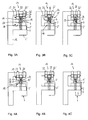
- FIGS. 3A to 3C a combined hot forming, punching and hardening tool 14 is shown, which is also referred to below as a tool for the sake of simplicity.
- the end-side section 15 of the first leg 8 is heated, which can be done by inductive heating.
- the length of the heated subsection 15 corresponds at least approximately to the length of the deformed end section 7 of the leg 8 to be produced.
- the tubular body 2 ' is quickly inserted into the tool, which results in FIG. 3A is shown.
- the combined hot forming, stamping and hardening tool 14 has a frame 16, an upper tool part 17 and a lower tool part 18.
- an upper mold insert 19 is provided, which cooperates with a corresponding lower mold insert 20 of the lower tool part 18.
- the upper tool part 17 is moved in the direction of the lower tool part 18, wherein the inserted therebetween tubular body 2 'at the end leg portion 15 of the mold inserts 19, 20 deformed or flattened and pressed.
- the two mold inserts 19, 20 form insofar parts of the hot forming device and can also be referred to as press or plate inserts.
- a drive unit 21 is provided, which may in particular comprise two hydraulic cylinders 22, 22 '.
- figure 3B shows the tool 14 with extended hydraulic cylinders 22, 22 'and correspondingly lowered upper tool part 17 and the deformed state of the tubular body 2'. It can be seen that the previously tubular partial section 15 of the leg 4 has been converted to the deformed section 7 with a flattened end region 8 and transition region 9.
- the tool 14 on the upper tool part 17 has a cutting device 23 for cutting the protruding end and a punching device 24 for punching the flattened end portion 8.
- the cutting device 23 and the punching device 24, which may also be referred to as a punching device, have a common drive unit 25, which in particular comprises a hydraulic cylinder. While the pressing force of the forming device 19, 20 is maintained for forming the leg 8, a knife and a punch pass through the mold inserts 18, 20 and punch the flattened portion 7 and cut the end.
- 3C shows the tool 14 with the hydraulic cylinder 25 extended and correspondingly lowered cutting and punching device 23, 24. It can be seen that a protruding end of the deformed portion 7 has been cut off and the through hole 10 has been incorporated into the flattened end portion 8.
- the hardening of the deformed end section 8 takes place by rapid cooling of the end section by surface contact of the workpiece with the mold or press inserts 18, 20.
- the rapid cooling takes place so rapidly that an at least partially martensitic structure is formed in the deformed end section 8.
- a diffusion of iron and carbon is avoided, so that the cubic face-centered austenite present after the heating of the section 15 converts into the tetragonal distorted body-centered lattice of the martensite by a sliding or folding process.
- the stabilizer 2 is removed from the tool 14. Subsequently, the second end 15 'or the second leg 8' is processed in analog form. This process is in the FIGS. 4A to 4C shown, which runs identically as the process for producing the first leg 8. Insofar, in this regard, the above description for processing the first leg 8 is abbreviated.
- the stabilizer can also be removed directly from the forming tool after hot forming and cured by separate means or cooled rapidly.
- the deformed end sections 8, 8 ' can be cooled by means of a liquid medium.
- the tube body may be internally blasted prior to forming and hardening the leg ends 7, 7 '.
- the stabilizer 2 can be externally blasted, coated and optionally provided with attachments.
- An advantage of the stabilizer 2 or of the method of production is that, due to the high strength of the end sections 7, 7 ', it can withstand high loads and has a long service life.
- the stabilizer ends 7, 7 ' can produce in a simple manner in a single tool 14, namely the described combined hot forming, punching and hardening tool 14 simple, fast and reliable.
- the hardening of the end portions 7, 7 ' not only causes a higher strength, but also has a positive effect on the tightness of the stabilizer 2, which contributes to an overall long life.
Landscapes
- Engineering & Computer Science (AREA)
- Chemical & Material Sciences (AREA)
- Mechanical Engineering (AREA)
- Materials Engineering (AREA)
- Metallurgy (AREA)
- Organic Chemistry (AREA)
- Physics & Mathematics (AREA)
- Thermal Sciences (AREA)
- Crystallography & Structural Chemistry (AREA)
- Vehicle Body Suspensions (AREA)
- Heat Treatment Of Articles (AREA)
Abstract
Description
- Die Erfindung betrifft einen Drehstab-Stabilisator für ein Fahrwerk eines Kraftfahrzeugs sowie ein Verfahren zur Herstellung eines solchen Stabilisators. Ein Drehstab-Stabilisator ist ein Federelement, das einem Wanken des Kraftfahrzeugs entgegenwirkt und so zur Verbesserung der Fahrdynamik beziehungsweise der Straßenlage des Kraftfahrzeugs beiträgt. Die Enden des Stabilisators werden mit jeweils einer Radaufhängung einer Fahrzeugachse verbunden. Zwischen den beiden Enden wird der Stabilisator an der Fahrzeugkarosserie befestigt.
- Aus der
US 2007/0216126 A1 ist ein Verfahren zur Herstellung eines rohrförmigen Stabilisators bekannt. Es wird ein Rohrkörper bereitgestellt, der erhitzt und anschließend abgeschreckt wird. Im abgeschreckten Zustand hat der Rohrkörper eine Festigkeit von etwa 1400 MPa. Anschließend wird der Rohrkörper zur gewünschten Form umgeformt, wobei der umgeformte Stabilisator einen im Wesentlichen länglichen Körper mit zwei Stabilisatorarmen mit ersten und zweiten Enden aufweist. Die Enden des Stabilisators sind abgeflacht und gelocht, so dass der Stabilisator mit der Aufhängung eines Kraftfahrzeugs verbunden werden kann. - Aus der
DE 11 2011 100 846 T5 sind ein massiver Stabilisator und ein Herstellungsverfahren des massiven Stabilisators bekannt. Das Herstellungsverfahren umfasst einen Formungsschritt, einen Härtungsschritt und einen Temper-Schritt. Beim Härtungsschritt werden die augenförmigen Endabschnitte eingespannt und Strom zwischen den augenförmigen Endabschnitten angelegt, um das Stahlmaterial auf eine Härungstemperatur von 970°C zu erwärmen. Danach wird das Stahlmaterial schnell abgekühlt und getempert. Nach dem Tempern beträgt die Härte in einem radialen Mittenabschnitt des massiven Stabilisators 400 HV. Die Zugfestigkeit beträgt 1.200 MPa oder mehr. - Aus der
US 2011/0290382 A1 ist ein Hochfestigkeitsstahl für einen Stabilisator bekannt, der 0,07% bis 0,2% C und 1% bis 3% Mn sowie weitere Legierungselemente enthält. Der Stabilisator hat einen Torsionsabschnitt und ein Paar von Armen mit Anschlusselementen an den Enden. Aus derUS 2014/0060709 A1 ist ein ähnlicher Stabilisator bekannt. - Aus der
DE 197 58 292 A1 ist ein Rohrstabilisator bekannt, bei dem die einzelnen Stabilisatorabschnitte so dimensioniert sind, dass in den wesentlichen Stabilisatorabschnitten eine quasigleiche Schwingfestigkeit gegeben ist. Es werden Grundfestigkeitswerte des Materials von beispielsweise 1.500 MPa bis 1.800 MPa angegeben. Durch Vergüten wird die Zugfestigkeit der Oberflächenrandschicht im Vergleich zur Zugfestigkeit eines entkohlten Materials erhöht. Die Wandstärke ist im Bereich des U-Rückens geringer als im gebogenen Übergangsbereich zu den Schenkeln. - Aus der
DE 10 2009 011 818 A1 ist ein Verfahren zur Herstellung eines Stabilisators mit zwei Stabilisatorlagern bekannt. Hierfür ist vorgesehene, dass der Stabilisator abschnittsweise erwärmt wird, dann mit dem Stabilisatorlager in Flächenkontakt gebracht und verpresst wird. - Aus der
DE 10 2013 101 276 A1 ist ein Verfahren zur Herstellung eines Kraftfahrzeugstabilisators bekannt. Hierfür ist vorgesehen, dass Bandmaterial aus einer hochmanganhaltigen Stahllegierung zu einem Rohrprofil umgeformt wird und anschließend mit Hochfrequenzschweißen zu einem Endlosrohr geschweißt wird. Das so hergestellte Rohr wird dann über einen Dorn nachgezogen, wobei je nach Umformgrad des Nachziehens gegebenenfalls ein Zwischenglühen stattfinden kann. Als Vorteil wird angegeben, dass der so hergestellte Stabilisator keiner Vergütungsbehandlung bedarf. - Die Endabschnitte von Stabilisatoren können aufgrund von Querschnittsveränderungen geometrisch und aufgrund von Umform- und Abkühlprozessen auch materialstrukturell eine verminderte Belastbarkeit haben. Die Wandstärken der Endabschnitte von Stabilisatoren sind üblicherweise entsprechend den von den radführenden Komponenten eingeleiteten Kräften beziehungsweise Belastungen ausgeführt.
- Bei hohen Belastungen und geringer Materialstärke der Stabilisatorenden kann es gegebenenfalls nötig sein, zusätzliche Verstärkungen einzubringen, was der Forderung nach Leichtbau entgegenwirkt. Ferner kann es unter Umständen zu Undichtigkeiten an den Stabilisatorenden kommen, die im schlimmsten Fall zum Bauteilversagen führen können.
- Hiervon ausgehend liegt der vorliegenden Erfindung die Aufgabe zugrunde, einen Stabilisator vorzuschlagen, der bei möglichst geringem Materialeinsatz hoch beanspruchbar ist und der bei guten Dichtigkeitseigenschaften einfach herstellbar ist. Die Aufgabe besteht ferner darin, ein entsprechendes Herstellungsverfahren vorzuschlagen, das die Herstellung eines hochbelastbaren und möglichst leichten Stabilisators, dessen Enden gute Dichtigkeitseigenschaften haben, prozesssicher ermöglicht.
- Eine Lösung besteht in einem gehärteten Drehstab-Stabilisator für ein Fahrwerk eines Kraftfahrzeugs, hergestellt aus einem Rohrkörper, umfassend: einen Torsionsfederabschnitt und zwei hiervon abgebogene Schenkel; wobei die Schenkel jeweils einen umgeformten Endabschnitt mit einer Durchgangsöffnung und einen rohrförmigen Abschnitt aufweisen; wobei der Torsionsfederabschnitt ein gehärtetes Gefüge mit einer Festigkeit von mindestens 1000 MPa aufweist; und wobei die umgeformten Endabschnitte ein gehärtetes Gefüge mit einer Festigkeit von mindestens 800 MPa aufweisen. Es ist insbesondere vorgesehen, dass die Schenkel im rohrförmigen Abschnitt jeweils einen Teilbereich mit einer Festigkeit aufweisen, die kleiner ist als die Festigkeit des Torsionsfederabschnitts.
- Ein Vorteil besteht darin, dass der Drehstab-Stabilisator aufgrund der hohen Festigkeit der Endabschnitte auch hohen Belastungen standhalten kann und eine lange Lebensdauer aufweist. Durch die hohe Festigkeit kann die Wandstärke der Endabschnitte gegebenenfalls reduziert werden, so dass bei gleichbleibender Belastbarkeit das Gewicht des Stabilisators reduziert werden kann. Die umgeformten und gehärteten Stabilisatorenden können beispielsweise einfach und prozesssicher durch Presshärten hergestellt werden.
- Der Stabilisator ist gehärtet beziehungsweise vergütet, womit im Rahmen der vorliegenden Offenbarung gemeint ist, dass der Stabilisator eine höhere Härte aufweist als das Ausgangsmaterial. Hierfür wird das Ausgangsmaterial erwärmt und anschließend abgeschreckt, so dass ein gegenüber dem Ausgangsgefüge härteres Gefüge entsteht. Vorzugsweise ist der Stabilisator aus einem härtbaren Stahlwerkstoff hergestellt, der zum Härten auf Austenitisierungstemperatur erhitzt und anschließend schnell abgekühlt wird. Durch das schnelle Abkühlen erfolgt eine zumindest teilweise, vorzugsweise vollständige Umwandlung des Gefüges zu Martensit. Dazu sind Stähle geeignet, bei denen im Zeit-Temperatur-Umwandlungsschaubild die Umwandlungen in der Perlit- und Bainitstufe zu längeren Zeiten verschoben sind, so dass die obere kritische Abkühlungsgeschwindigkeit verhältnismäßig niedrig ist und auch im Kern des Werkstücks noch erreicht werden kann. Vorzugsweise hat der Stahlwerkstoff einen Kohlenstoffgehalt von weniger als 0,5 Gewichtsprozent und/oder einem Mangangehalt von 0,5 bis 3,0 Gewichtsprozent.
- Nach dem Härten kann der Stabilisator angelassen werden. Durch das Anlassen nimmt die Festigkeit des zunächst spröden Martensits ab, die Zähigkeit aber zu. Insgesamt können durch geeignete Anlasstemperaturen die gewünschten Eigenschaftskombinationen des Bauteils erreicht werden. Die Kombination von Härten und anschließendem Anlassen des Bauteils wird auch als Vergüten bezeichnet.
- Die Härte und die Festigkeit des Stabilisators bedingen einander. Entsprechend der gewünschten Festigkeit kann der Torsionsfederabschnitt nach einer möglichen Ausgestaltung eine Härte von mindestens 310 HV, vorzugsweise mindestens 410 HV, insbesondere von mindestens 500 HV haben. Die umgeformten Endbereiche können eine Härte von mindestens 250 HV, vorzugsweise mindestens 310HV, insbesondere von mindestens 400 HV aufweisen.
- Der Stabilisator kann aus einem Rohrkörper als Ausgangsmaterial hergestellt werden, von dem die Schenkel abgebogen werden. Die umgeformten Endabschnitte der Schenkel können durch Warmumformen hergestellt werden. Hierfür werden die umzuformenden Endabschnitte zunächst erwärmt, so dass die Härte in diesen Abschnitten gegenüber der Härte des Ausgangsmaterials wieder reduziert wird, und anschließend umgeformt. Es ist insbesondere vorgesehen, dass die umgeformten Endabschnitte jeweils einen flachen Endbereich aufweisen, der gelocht ist, und einen hieran anschließenden Übergangsbereich. Die durch die Lochung entstehenden Durchgangsöffnungen dienen zum Verbinden des Stabilisators mit einem Anschlussbauteil, beispielsweise einer Fahrwerkskomponente des Kraftfahrzeugs. Vorzugsweise sind die Endabschnitte beziehungsweise die Endbereiche flüssigkeitsdicht und/oder gasdicht verschlossen. Dies kann im Wege der Umformoperation zur Herstellung der umgeformten Endabschnitte erfolgen. Insbesondere ist vorgesehen, dass die Herstellung derart erfolgt, dass die Stabilisatorenden bis mindestens 2 bar Innendruck gasdicht sind und/oder der Innendruck nach 5 Minuten noch mindestens das 0,75-fache des maximal aufgebrachten Drucks beträgt. Dabei trägt das gehärtete Gefüge der Endbereiche neben dem Umformprozess zum Erreichen dieser Dichtigkeitswerte bei.
- Der Übergangsbereich zwischen dem abgeflachten Endbereich und dem Rohrabschnitt des Schenkels hat einen variablen Querschnitt über der Länge des Übergangsbereichs. Mit anderen Worten bildet der Übergangsbereich einen querschnittsverändernden Übergang zwischen dem flachen Endbereich und dem rohrförmigen Schenkelabschnitt. Der Übergangsbereich hat eine Festigkeit von vorzugsweise mindestens 800 MPa, insbesondere von mindestens 1000 MPa, je nach technischen Anforderungen auch mehr als 1200 MPa. Nach einer günstigen Ausgestaltung hat der Übergangsbereich zumindest annähernd dieselbe Festigkeit und Härte wie der gelochte Endbereich des Schenkels.
- An den Übergangsbereich schließt sich der rohrförmige Schenkelabschnitt an, der einen Teilbereich mit geringer Festigkeit beziehungsweise Härte aufweisen kann. Insbesondere kann die Festigkeit beziehungsweise Härte dieses Teilbereichs geringer sein als die Festigkeit beziehungsweise Härte des Torsionsfederabschnitts und/oder als die Festigkeit beziehungsweise Härte des Endbereichs, wobei die Festigkeit und Härte des Torsionsfederabschnitts insbesondere der Grundfestigkeit und Grundhärte des vergüteten Stabilisators entsprechen kann. Beispielsweise kann die Festigkeit in diesem Teilbereich des rohrförmigen Schenkelabschnitts kleiner als das 0,7-fache der Festigkeit des Torsionsfederabschnitts und/oder des Endabschnitts sein. Alternativ oder in Ergänzung kann die Festigkeit des genannten Teilbereichs größer als das 0,5-fache der Festigkeit des Torsionsfederabschnitts und/oder des Endabschnitts sein. Die Härte des Materials steht mit der Festigkeit in Zusammenhang, so dass die genannten Werte auch entsprechend für die Härte gelten können. Damit der Teilbereich mit verminderter Festigkeit keine negative Auswirkung auf die Gesamtfestigkeit und Lebensdauer des Stabilisators hat, ist insbesondere vorgesehen, dass dieser vom Übergangsbereich einen Abstand aufweist, der vorzugsweise mindestens dem halben Durchmesser des rohrförmigen Schenkelabschnitts entspricht.
- Nach einer möglichen Ausgestaltung kann der Drehstab-Stabilisator eine variable Wanddicke über der Länge aufweisen. Dabei kann die Wandstärke entsprechend den technischen Bedürfnissen eingestellt werden, das heißt an höher belasteten Stellen kann eine größere Wandstärke vorgesehen werden beziehungsweise an Stellen, in denen eine größere Elastizität gewünscht ist, kann die Wandstärke entsprechend geringer ausgestaltet sein. Insbesondere ist vorgesehen, dass eine Wanddicke zumindest der Endbereiche kleiner ist als eine maximale Wanddicke des Drehstab-Stabilisators. Beispielsweise kann die Wanddicke der Endbereiche mindestens 20 % kleiner sein als die maximale Wanddicke des Stabilisators. Die maximale Wanddicke ist insbesondere in den Biegeabschnitten gebildet. Auch eine mittlere Wanddicke des Übergangsbereichs kann gegenüber einer maximalen Wanddicke des Stabilisators vermindert sein.
- Die Lösung der oben genannten Aufgabe besteht ferner in einem Verfahren zum Herstellen eines Drehstab-Stabilisators für ein Fahrwerk eines Kraftfahrzeugs, mit den Schritten: Herstellen eines Rohres; Abbiegen von Schenkeln von dem Rohr; Vergüten des Rohres vor oder nach dem Abbiegen der Schenkel, so dass das gehärtete Rohr ein Härtegefüge mit einer Festigkeit von mindestens 1000 MPa aufweist; Erwärmen eines endseitigen Teilabschnitts der Schenkel nach dem Härten beziehungsweise Vergüten des Rohres, wobei die Festigkeit im endseitigen Teilabschnitt auf unter 800 MPa reduziert wird; Warmumformen des endseitigen Teilabschnitts nach dem Erwärmen zur Erzeugung eines umgeformten Endabschnitts; Stanzen des umgeformten Endabschnitts zur Erzeugung einer Durchgangsöffnung; Härten des umgeformten Endabschnitts derart, dass im umgeformten Endabschnitt ein gehärtetes Gefüge mit einer Festigkeit von mindestens 800 MPa aufweisen.
- Das erfindungsgemäße Verfahren bietet analog dieselben Vorteile wie das erfindungsgemäße Erzeugnis, so dass diesbezüglich auf obige Beschreibung verwiesen wird. Es versteht sich, dass alle erzeugnisbezogenen Merkmale auf das Verfahren übertragbar sind, und umgekehrt. Insgesamt kann der erfindungsgemäße Stabilisator aufgrund der hohen Festigkeit der Endabschnitte auch hohen Belastungen standhalten und hat eine lange Lebensdauer, beziehungsweise es lässt sich bei gleicher Belastung des Stabilisators Material und Gewicht einsparen. Beim erfindungsgemäßen Prozess durchlaufen die Endabschnitte zwei Härteprozesse, nämlich einen ersten im Rahmen der Vergütung des als Ausgangsmaterial dienenden Rohres, und einen zweiten, nämlich beim nach dem Umformen durchgeführten partiellen Härten der Endabschnitte.
- Nach einer möglichen Verfahrensführung kann das Erwärmen der endseitigen Teilabschnitte mittels induktiver Erwärmung erfolgen. Beim induktiven Erwärmen erfolgt ein Aufheizen im elektrisch leitfähigen Bauteil durch hierin erzeugte Wirbelstromverluste, wobei die Wärme unmittelbar im Bauteil selbst entsteht. Als Vorrichtung zur induktiven Erwärmung kann eine Induktionsspule, Induktionsheizung oder ein Induktionsofen verwendet werden. Die Induktionsvorrichtung erzeugt über eine von Wechselstrom durchflossene Spule ein magnetisches Wechselfeld, das im Bauteil Wirbelströme induziert.
- Es ist insbesondere vorgesehen, dass die Schritte Warmumformen des endseitigen Teilabschnitts und Stanzen einer Durchgangsöffnung in den umgeformten Endabschnitt in einem gemeinsamen Werkzeug durchgeführt werden.
- Das Härten der umgeformten Endabschnitte kann nach einer ersten Möglichkeit in demselben Werkzeug durchgeführt werden, wie das Warmumformen und Stanzen. In diesem Fall wäre das Werkzeug als kombiniertes Warmumform-, Stanz- und Härtewerkzeug auszuführen. Durch das Warmumformen, Stanzen und Härten in einem einzigen Werkzeug wird eine schnelle Herstellung mit kurzen Taktzeiten ermöglicht. Insbesondere kann vorgesehen sein, dass zunächst ein Schenkel des Stabilisators an dessen endseitigem Teilabschnitt erwärmt wird, dann in das kombinierte Warmumform-, Stanz- und Härtewerkzeug eingelegt wird, wobei der endseitige Teilabschnitt zum umgeformten Endabschnitts umgeformt, das Loch in den Endabschnitt gestanzt und der Endabschnitt durch schnelles Abkühlen gehärtet werden. Dann wird der Stabilisator mir seinem umgeformten und gehärteten ersten Schenkel aus dem Werkzeug entnommen, so dass anschließend der zweite Schenkel entsprechend hergestellt werden kann. Das kombinierte Werkzeug ist vorzugsweise so gestaltet, dass die Bearbeitungsreihenfolge des Schenkels in der Chronologie Umformen, Lochen und Härten erfolgt. Grundsätzlich ist es jedoch auch denkbar, dass das Lochen mit zeitlicher Überlappung oder nach dem Härten durchgeführt wird. Ein Vorteil der Herstellung in dem kombinierten Werkzeug ist, dass der Energiebedarf für die Herstellung insgesamt niedrig ist, da das Bauteil zum Warmumformen und Härten nur einmal erwärmt werden muss. Das Verfahren des kombinierten Warmumformens und Härtens kann auch als Presshärten bezeichnet werden.
- Nach einer alternativen Möglichkeit kann das Härten der umgeformten Endabschnitte auch als separater Verfahrensschritt mittels einer separaten Vorrichtung durchgeführt werden. Dabei kann das Härten zeitlich an den Warmumformprozess anknüpfen, insbesondere derart, dass der Stabilisator aus dem Werkzeug entnommen und mittels der Vorrichtung weiter schnell abgekühlt wird. Das schnelle Abkühlen kann beispielsweise mittels eines Luftvolumenstroms oder in einem Flüssigkeitsbad, wie einem Öl oder Wasserbad durchgeführt werden. Das Härten kann aber auch zeitlich und räumlich von dem kombinierten Warmumform- und Stanzprozess getrennt sein. In diesem Fall wären die umgeformten Endabschnitte des Stabilisators zunächst auf Austenitisierungstemperatur zu erhitzen und anschließend schnell in einer Kühlvorrichtung abzukühlen. Bei dem separaten Härteprozess ist es nach einer ersten Variante möglich, zunächst beide Endabschnitte auf Austenitisierungstemperatur zu erhitzen und anschließend in der Härte- bzw. Kühlvorrichtung schnell abzukühlen. Nach einer zweiten Variante können die beiden Endabschnitte auch nacheinander jeweils erhitzt und abgekühlt werden.
- Nach einer möglichen Verfahrensführung kann das Herstellen des Rohres durch die Teilschritte: Walzen eines Stahlbandes; Einformen des Stahlbandes zum geschlitzten Rohrkörper; und Längsschweißen des geschlitzten Rohrkörpers zum geschlossenen Rohr erfolgen. Zur Erzeugung einer variablen Blechdicke über der Länge des Stabilisators kann nach einer ersten Möglichkeit das Rohr durch Ziehen über einem abgestuften Dorn hergestellt werden. Die so hergestellten Rohre werden auch als Tailor Drawn Tube bezeichnet. Alternativ kann die variable Wanddicke des Stabilisators auch dadurch hergestellt werden, dass das als Ausgangsmaterial für das Rohr verwendete Stahlband mittels Flexiblem Walzen bearbeitet wird, bevor es zum Rohr umgeformt wird. Beim Flexiblen Walzen wird Bandmaterial mit im Wesentlichen einheitlicher Blechdicke durch Verändern des Walzspalts während des Prozesses zu Bandmaterial mit variabler Blechdicke über der Länge ausgewalzt. Die durch das Flexible Walzen erzeugten Abschnitte unterschiedlicher Dicke erstrecken sich quer zur Längsrichtung beziehungsweise zur Walzrichtung des Bandmaterials. Das Bandmaterial kann nach dem Flexiblen Walzen wieder zum Coil aufgewickelt werden und an anderer Stelle der Weiterverarbeitung zugeführt werden, oder es kann direkt weiterverarbeitet werden, beispielsweise durch Umformen zum Rohrkörper und Längsverschweißen. Alternativ kann das Rohr auch nahtlos als gezogenes Rohr hergestellt werden.
- Das Vergüten des Rohres erfolgt durch die Teilschritte: Erwärmen des Rohres auf Austenitisierungstemperatur; Abschrecken des erwärmten Rohres; und Anlassen des abgeschreckten Rohres. Mit Erhitzen des Materials auf Austenitisierungstemperatur ist gemeint, dass das Material auf eine Temperatur erhitzt wird, bei der zumindest teilweise Austenit entsteht. Die Austenitisierungstemperatur liegt vorzugsweise oberhalb des Ac3-Punktes, das heißt für Stahlwerkstoffe vorzugsweise oberhalb 800°C. Das anschließende Abschrecken auf eine niedrigere Temperatur erfolgt insbesondere zwischen der oberen und unteren kritischen Abkühlgeschwindigkeit, das heißt derart schnell, dass zumindest teilweise Martensit entsteht. Durch das Abschrecken wird eine Diffusion von Eisen und Kohlenstoff vermieden, so dass sich der kubisch flächenzentrierte Austenit in das tetragonal verzerrte raumzentrierte Gitter des Martensit durch einen Schiebungs- oder Umklappprozess umwandelt. Je nach Abkühlgeschwindigkeit können auch Zwischengefüge beziehungsweise Bainit entstehen. Nach dem Abschrecken erfolgt das Anlassen, wobei das gehärtete Rohr auf mäßig hohe Temperaturen unterhalb der A1-Temperatur erwärmt und anschließende wieder abgekühlt wird. Durch das Anlassen werden innere Spannungen abgebaut, das heißt Härte und Festigkeit verringern sich, während die Zähigkeit ansteigt. Die Prozesskombination aus Härten und Anlassen wird auch als Vergüten bezeichnet.
- Bevorzugte Ausführungsformen werden nachstehend anhand der Zeichnungsfiguren beschrieben. Hierin zeigt:
- Figur 1
- einen erfindungsgemäßen Drehstab-Stabilisator in Draufsicht
- A) mit Härteverlauf über der Länge;
- B) mit Wanddickenverlauf über der Länge;
- Figur 2
- das Detail X des Drehstab-Stabilisators aus
Figur 1 - A) in Draufsicht;
- B) in Seitenansicht;
- C) mit Härteverlauf;
- Figur 3
- eine Vorrichtung zum Herstellen eines Stabilisators gemäß
Figur 1 A in verschiedenen Schritten- A) mit in die Vorrichtung zum Bearbeiten eingelegten ersten Schenkel;
- B) nach dem Umformen eines endseitigen Teilabschnitts des ersten Schenkels;
- C) nach dem Schneiden und Lochen des umgeformten Teilabschnitts des ersten Schenkels;
- Figur 4
- die Vorrichtung aus
Figur 3 - A) mit in die Vorrichtung zum Bearbeiten eingelegten zweiten Schenkel;
- B) nach dem Umformen eines endseitigen Teilabschnitts des zweiten Schenkels;
- C) nach dem Schneiden und Lochen des umgeformten Teilabschnitts des zweiten Schenkels.
- Die
Figuren 1 und2 , welche nachstehend gemeinsam beschrieben werden, zeigen einen erfindungsgemäßen Stabilisator 2 für den Einsatz im Fahrwerk eines Kraftfahrzeugs. Der Stabilisator 2 weist einen Torsionsfederabschnitt 3, der auch als Drehstabfederabschnitt oder Stabilisatorrücken bezeichnet werden kann, und zwei von dem Torsionsfederabschnitt 3 winklig abgebogene Schenkel 4, 4' auf, die auch als Hebelarme bezeichnet werden können. Zwischen dem Torsionsfederabschnitt 3 und den Schenkeln 4, 4' ist jeweils ein Biegeabschnitt 5, 5' gebildet. Es ist erkennbar, dass der vorliegende Stabilisator 2 relativ zu einer Mittelebene E spiegelsymmetrisch aufgebaut ist und an beiden Enden einen Schenkel 4, 4' aufweist. Es versteht sich jedoch, dass der Stabilisator auch unsymmetrisch gestaltet sein kann und je nach Bauraumverhältnissen auch ungleich gestaltete Schenkel aufweisen kann. Sofern im Rahmen der vorliegenden Offenbarung nur auf einen der Schenkel 4, 4' Bezug genommen wird, so versteht es sich, dass dies stets auch für den anderen Schenkel 4', 4 des Stabilisators gilt. - Der Torsionsfederabschnitt 3 verläuft im Wesentlichen gerade und wird beispielsweise mittels zweier Lager (nicht dargestellt) an der Fahrzeugkarosserie befestigt, beispielsweise im Motorraum oder am Unterboden des Kraftfahrzeugs. Die Schenkel 4, 4' dienen zum Verbinden des Stabilisators 2 mit den beiden Radaufhängungen (nicht dargestellt) einer Achse des Kraftfahrzeugs. Vorliegend verlaufen die Schenkel 4, 4' im Wesentlichen gerade und schließen mit dem Torsionsfederabschnitt 3 in Draufsicht auf den Stabilisator 2 einen rechten Winkel ein. Es versteht sich jedoch, dass die Schenkel, je nach Bauraumverhältnissen und Anwendung, auch andere Ausgestaltungen haben können. Beispielsweise können die Schenkel auch gekröpft oder gebogen sein und/oder unter einem Winkel ungleich 90° zum Torsionsfederabschnitt 3 verlaufen.
- Durch die Verbindung der Schenkel 4, 4' des Stabilisators 2 mit jeweils einer zugehörigen Radaufhängung des Kraftfahrzeugs, werden die beiden Radaufhängungen federnd aneinander gekoppelt. Bei Kurvenfahrten wird durch ein einseitiges Einfedern des kurvenäußeren Fahrzeugrades und gleichzeitiges Ausfedern des kurveninneren Rades ein Wanken des Kraftfahrzeugs verursacht. Diese Einfederbewegung wird über den einfedernden Schenkel 4, 4' und den Torsionsfederabschnitt 3 auf den gegenüberliegenden Schenkel 4', 4 übertragen. Auf diese Weise wird einem Wanken des Kraftfahrzeugs, das heißt einer Drehbewegung um die Fahrzeuglängsachse, entgegengewirkt.
- Der Stabilisator 2 wird aus einem einteiligen im Querschnitt geschlossenen Rohrkörper hergestellt, von dem Endabschnitte abgebogen sind, welche die Schenkel 4, 4' bilden. Als Ausgangsmaterial wird ein härtbarer Stahlwerkstoff verwendet, der vorzugsweise einen Kohlenstoffgehalt von weniger als 0,5 Gewichtsprozent und einen Mangangehalt von 0,5 bis 3,0 Gewichtsprozent aufweist. Neben Eisen können weitere übliche Legierungselemente wie Chrom und/oder Bor enthalten sein. Der Stabilisator 2 beziehungsweise der Rohrkörper zur Herstellung des Stabilisators ist vergütet, das heißt gehärtet und angelassen. Dabei kann der Rohrkörper vor oder nach dem Abbiegen der Schenkel 4, 4' vergütet werden.
- Jeder der Schenkel 4, 4' hat, ausgehend vom Biegeabschnitt 5, 5' einen rohrförmigen Abschnitt 6, 6' mit einem zumindest etwa gleichbleibendem Querschnitt über der Länge und einen umgeformten Endabschnitt 7, 7'. Die umgeformten Endabschnitte 7, 7' weisen jeweils einen abgeflachten Bereich 8, 8' und einen Übergangsbereich 9, 9' auf. Der Übergangsbereich 9, 9' verbindet den abgeflachten Endbereich 8, 8' mit dem rohrförmigen Schenkel 6, 6' und haben entsprechend einen variablen Querschnitt über der Länge des jeweiligen Übergangsbereichs 9, 9'.
- Es ist insbesondere in
Figur 2B erkennbar, dass die flachen Endbereiche 8, 8' der umgeformten Endabschnitte 7, 7' gelocht sind. Dabei dienen die Durchgangsöffnungen 10, 10' zum Verbinden des Stabilisators 2 mit einer Fahrwerkskomponente des Kraftfahrzeugs. Die flachen Endbereiche 8, 8' sind flüssigkeitsdicht beziehungsweise gasdicht verschlossen, und zwar vorzugsweise bis mindestens 2 bar Innendruck, so dass ein Eindringen von Schmutz und Wasser verhindert wird. Das gasdichte Verschließen erfolgt im Rahmen der Umformoperation. Dabei ist es günstig, wenn die Stabilisatorenden derart gasdicht sind, dass der Innendruck nach 5 Minuten noch mindestens das 0,75-fache des maximal aufgebrachten Drucks beträgt. - Es ist ferner in
Figur 2A erkennbar, dass die Übergangsbereiche 9, 9' zwischen dem jeweils anschließenden flachen Endbereich 8, 8' und dem Rohrabschnitt 6, 6' des Schenkels 4, 4' einen variablen Querschnitt über der Länge haben, so dass ein querschnittsverändernder Übergang zwischen dem flachen Endbereich 8, 8' und dem rohrförmigen Schenkelabschnitt 6, 6' gebildet ist. - Wie oben bereits erwähnt, ist der Stabilisator 2 aus einem vergüteten Stahlwerkstoff hergestellt. Dabei beträgt die Grundfestigkeit des vergüteten Stahlwerkstoffs, je nach Ausgangsmaterial, mindestens 1000 MPa, insbesondere mindestens 1200 MPa, gegebenenfalls auch mindestens 1400 MPa. Beispielsweise kann ein Stabilisator-Rohrkörper aus vergütetem Stahlmaterial 26MnB5 eine Grundfestigkeit von etwa 1400 MPa bis 1585 MPa aufweisen. Ein Rohrkörper aus vergütetem Stahlmaterial 34MnB5 kann eine noch höhere Grundfestigkeit von etwa 1585 MPa bis 1680 MPa aufweisen.
- In fertig hergestelltem Zustand des Stabilisators haben die umgeformten Endabschnitte 7, 7' eine Festigkeit von mindestens 800 MPa, insbesondere von mindestens 1000 MPa. Die Festigkeit der umgeformten Endabschnitte 7, 7' kann geringer als die Grundfestigkeit des vergüteten Stahlmaterials sein und insbesondere mindestens das 0,8-fache bis 0,9-fache der Festigkeit des vergüteten Stahlmaterials betragen. Bei einer Festigkeit des vergüteten Stahlmaterials von 1200 MPa könnte die Festigkeit der umgeformten Endabschnitte 7, 7' demnach zwischen 960 MPa und 1080 MPa liegen.
- Die Festigkeit des Stabilisators korreliert mit der Härte, für die ein beispielhafter Verlauf in
Figur 1A und, als vergrößertes Detail für einen der Schenkel 4, 4' des Stabilisators 2, inFigur 2C dargestellt ist. Dabei ist die Grundhärte des Stabilisators ist mit H2 bezeichnet und die Härte der Endabschnitte 7, 7' mit H7. Eine mittlere Grundhärte ist mit 0,5H2 angegeben. Es ist erkennbar, dass die Härte H7 der Endabschnitte 7, 7' etwas geringer ist als die Grundhärte H2, insbesondere etwa dem 0,9-fachen der Grundhärte H2 entspricht. Beispielhafte Werte für die Härte des Stabilisators 2 lassen sich wie folgt angeben. Die Grundhärte H2 kann mindestens 410 HV, insbesondere mindestens 500 HV betragen. Die umgeformten Endabschnitte 7, 7' können eine Härte H7 von mindestens 310 HV, insbesondere von mindestens 400 HV aufweisen. - Weiter ist erkennbar, dass die Endabschnitte 7, 7' ausgehend von einer Stirnseite Ende 12, 12' über den jeweiligen Endbereich 8, 8' und den daran anschließenden Übergangsbereich 9, 9' hinaus eine im Wesentlichen gleichbleibende Härte H7 beziehungsweise Festigkeit aufweist, die insbesondere größer als das 0,8-fache der Grundhärte H2 beziehungsweise Grundfestigkeit des Stabilisators 2 ist. Erst im rohrförmigen Abschnitt 6, 6' des Schenkels 4, 4', der geometriebedingt ein größeres Flächenträgheitsmoment aufweist als der umgeformte Endabschnitt 7, 7', liegt ein Teilbereich 13, 13' mit reduzierter Härte Hmin beziehungsweise reduzierter Festigkeit vor. Dabei ist die reduzierte Härte Hmin beziehungsweise reduzierte Festigkeit kleiner als die Grundhärte beziehungsweise Grundfestigkeit des Stabilisators 2, respektive als die Härte beziehungsweise Festigkeit des Torsionsabschnitts 3. Vorliegend ist die reduzierte Härte Hmin insbesondere kleiner als das 0,7-fache der Grundhärte des Stabilisators 2 und größer als die mittlere Grundhärte 0,5H2 des Stabilisators 2, das heißt 0,7H2 > Hmin > 0,5H2. Dies kann für die Festigkeit entsprechend gelten. Der weiche Teilbereich 13, 13' ist von dem Übergangsbereich 9, 9' deutlich beabstandet, insbesondere um eine Länge die größer ist als ein halber Durchmesser D6 des rohrförmigen Schenkelabschnitts 6, 6'.
- In
Figur 1 B ist der Wanddickenverlauf d des Stabilisators 2 über der Länge L eingezeichnet. Es ist erkennbar, dass der Drehstab-Stabilisator eine variable Wanddicke d über der Länge L hat, wobei es sich versteht, dass die Wanddicke auch gleichbleibend über der Länge sein kann. Vorliegend ist der Wanddickenverlauf in Bezug auf eine Mittelebene des Stabilisators symmetrisch. Konkret ist insbesondere vorgesehen, dass die Wanddicke d4 der Schenkel 4, 4' gegenüber der Wanddicke d5 der Biegeabschnitte 5, 5' reduziert ist. In den Biegeabschnitten 5, 5' hat der Stabilisator die größte Wanddicke d5. Ausgehend von den beiden Biegeabschnitten 5, 5' in Richtung Mittelebene hat der Stabilisator im Torsionsfederabschnitt 3 wiederum eine reduzierte Wanddicke d3, welche vorliegend zwei Teilbereiche mit unterschiedlicher Dicke umfasst. Es versteht sich, dass in Abhängigkeit von den Belastungen des Stabilisators auch eine von zwei abweichende Zahl von Teilbereichen wie eins, drei oder mehr als drei in den Stabilisator 2 eingearbeitet sein kann. Die Übergangsbereiche zwischen jeweils zwei Wanddickenbereichen d3, d4, d5 sind stetig, so dass sich eine möglichst gleichmäßige Beanspruchung ergibt und Spannungsspitzen vermieden werden. Konkret ist insbesondere vorgesehen, dass die umgeformten Endabschnitte 7, 7' eine Wanddicke d7 haben, die um mindestens 20 % kleiner als die maximale Wanddicke d5 des Stabilisators ist. - Zur Herstellung eines Rohrkörpers mit variabler Dicke über der Länge kann beispielsweise ein zunächst mit gleichbleibender Wanddicke hergestelltes Rohr über einem abgestuften Dorn gezogen werden, so dass im Rohr Abschnitte mit unterschiedlicher Wandstärke erzeugt werden (Tailor Drawn Tube). Alternativ kann das Rohr bereits aus flexibel gewalztes Bandmaterial als Ausgangsmaterial hergestellt werden, worauf weiter unten noch näher eingegangen wird. Derartig flexibel gewalztes Bandmaterial wird auch als Tailor Rolled Blank bezeichnet.
- Ein erfindungsgemäßes Verfahren zur Herstellung des Stabilisators 2 umfasst die folgenden Verfahrensschritte: Herstellen eines Rohres; Abbiegen der Schenkel 8, 8' von dem Rohr; Vergüten des Rohres vor oder nach dem Abbiegen der Schenkel, so dass das vergütete Rohr ein Härtegefüge mit einer Festigkeit von mindestens 1000 MPa aufweist; Erwärmen eines endseitigen Teilabschnitts eines der Schenkel 8, 8' nach dem Härten des Rohres, wobei die Festigkeit im endseitigen Teilabschnitt auf unter 800 MPa reduziert wird; Warmumformen des endseitigen Teilabschnitts nach dem Erwärmen zur Erzeugung des umgeformten Endabschnitts 7, 7'; Stanzen des umgeformten Endabschnitts 7, 7' zur Erzeugung der Durchgangsöffnung 10, 10'; Härten des umgeformten Endabschnitts derart, dass im umgeformten Endabschnitt ein gehärtetes Gefüge mit einer Festigkeit von mindestens 800 MPa aufweisen. Anschließend wird der zweite Schenkel 8', 8 in entsprechender Weise bearbeitet.
- Das Herstellen des Rohres kann durch die Teilschritte: Walzen eines Stahlbandes; Einformen des Stahlbandes zu einem geschlitzten Rohrkörper; und Längsschweißen des geschlitzten Rohrkörpers zum geschlossenen Rohr erfolgen. Zur Erzeugung einer variablen Blechdicke über der Länge des Stabilisators 2 kann das Stahlband vor dem Umformen zum Rohr zuvor flexibel gewalzt werden, oder es kann ein Rohr mit zunächst konstanter Wandstärke nach dem Schweißen flexibel gezogen werden. Beim Flexiblen Walzen erhält das Bandmaterial während des Prozesses durch Verändern des Walzspalts eine variable Blechdicke über der Länge. Das Abbiegen der Schenkel 8, 8' erfolgt in einer entsprechenden Biegevorrichtung. Das Vergüten des Rohres erfolgt durch die Teilschritte: Erwärmen des Rohres auf Austenitisierungstemperatur; Abschrecken des erwärmten Rohres; und Anlassen des abgeschreckten Rohres. Das Vergüten erfolgt vorzugsweise nach dem Abbiegen der Schenkel 8, 8', kann prinzipiell aber auch vorher durchgeführt werden. Nach dem Vergüten liegt der vergütete Rohrkörper 2' mit im Wesentlichen konstantem Querschnitt über der Länge L des Rohrkörpers und der oben genannten Grundfestigkeit von mindestens 1000 MPa vor.
- Hiervon ausgehend werden die endseitigen Teilabschnitte der Schenkel 8, 8' erzeugt, was nachstehend anhand der
Figuren 3A bis 3C erläutert wird. - In den
Figuren 3A bis 3C ist ein kombiniertes Warmumform-, Stanz- und Härtewerkzeug 14 gezeigt, das im Folgenden der Einfachheit halber auch kurz Werkzeug bezeichnet wird. Vor dem Einlegen des vergüteten Rohrkörpers 2' in das Werkzeug 14 wird der endseitige Teilabschnitt 15 des ersten Schenkels 8 erwärmt, was durch induktive Erwärmung erfolgen kann. Die Länge des erwärmten Teilabschnitts 15 entspricht zumindest etwa der Länge des herzustellenden umgeformten Endabschnitts 7 des Schenkels 8. Nach dem Erwärmen des Teilabschnitts 15 wird der Rohrkörper 2' schnell in das Werkzeug eingelegt, was inFigur 3A gezeigt ist. - Das kombinierte Warmumform-, Stanz- und Härtewerkzeug 14 weist ein Gestell 16, ein oberes Werkzeugteil 17 und ein unteres Werkzeugteil 18 auf. Am oberen Werkzeugteil 17 ist ein oberer Formeinsatz 19 vorgesehen, der mit einem entsprechenden unteren Formeinsatz 20 des unteren Werkzeugteils 18 zusammenwirkt. Zum Umformen des Schenkels 8 wird das obere Werkzeugteil 17 in Richtung zum unteren Werkzeugteil 18 bewegt, wobei der dazwischen eingelegte Rohrkörper 2' an dem endseitigen Schenkelabschnitt 15 von den Formeinsätzen 19, 20 umgeformt, beziehungsweise geplättet und gepresst wird. Die beiden Formeinsätze 19, 20 bilden insofern Teile der Warmumformvorrichtung und können auch als Press- oder Plätteinsätze bezeichnet werden. Zum Bewegen des oberen Werkzeugteils 17 ist eine Antriebseinheit 21 vorgesehen, die insbesondere zwei Hydraulikzylinder 22, 22' umfassen kann.
Figur 3B zeigt das Werkzeug 14 mit ausgefahrenen Hydraulikzylindern 22, 22' und entsprechend abgesenktem oberen Werkzeugteil 17 sowie den umgeformten Zustand des Rohrkörpers 2'. Es ist erkennbar, dass der zuvor rohrförmige Teilabschnitt 15 des Schenkels 4 zum umgeformten Abschnitt 7 mit abgeflachtem Endbereich 8 und Übergangsbereich 9 umgeformt worden ist. - Nachfolgend wird das überstehende Ende des umgeformten Abschnitts 7 abgeschnitten und der abgeflachte Endbereich 8 gelocht. Hierfür hat das Werkzeug 14 am oberen Werkzeugteil 17 eine Schneidvorrichtung 23 zum Beschneiden des überstehenden Endes und eine Stanzvorrichtung 24 zum Lochen des abgeflachten Endbereichs 8. Die Schneidvorrichtung 23 und die Stanzvorrichtung 24, die auch als Lochvorrichtung bezeichnet werden kann, haben eine gemeinsame Antriebseinheit 25, die insbesondere einen Hydraulikzylinder umfasst. Während die Pressenkraft der Umformvorrichtung 19, 20 zum Umformen des Schenkels 8 aufrechterhalten wird, fahren ein Messer und ein Stempel durch die Formeinsätze 18, 20 und Lochen den abgeflachten Bereich 7 und beschneiden das Ende.
Figur 3C zeigt das Werkzeug 14 mit ausgefahrenem Hydraulikzylinder 25 und entsprechend abgesenkter Schneid- und Stanzvorrichtung 23, 24. Es ist erkennbar, dass ein überstehendes Ende des umgeformten Abschnitts 7 abgeschnitten und die Durchgangsöffnung 10 in den abgeflachtem Endbereich 8 eingearbeitet worden ist. - Das Härten des umgeformten Endabschnitts 8 erfolgt durch schnelles Abkühlen des Endabschnitts durch flächigen Kontakt des Werkstücks mit den Form- beziehungsweise Presseneinsätzen 18, 20. Das schnelle Abkühlen erfolgt derart schnell, dass ein zumindest teilweise martensitisches Gefüge im umgeformten Endabschnitt 8 entsteht. Dabei wird eine Diffusion von Eisen und Kohlenstoff vermieden, so dass der nach dem Erwärmen des Teilabschnitts 15 vorliegende kubisch flächenzentrierte Austenit in das tetragonal verzerrte raumzentrierte Gitter des Martensit durch einen Schiebungs- oder Umklappprozess umwandelt. Von Vorteil ist dabei im Hinblick auf die Dichtigkeit des abgeflachten Endbereichs 8 ist, dass Martensit aufgrund seiner Gitterstruktur ein etwas größeres Volumen hat als Austenit, so dass die aufeinander liegenden Wandungen des abgeflachten Endbereichs 8 besonders fest und dicht aufeinander liegen.
- Nach dem Herstellen des umgeformten und gehärteten Abschnitts 7 des ersten Schenkels 8 wird der Stabilisator 2 aus dem Werkzeug 14 entnommen. Anschließend wird das zweite Ende 15' beziehungsweise der zweite Schenkel 8' in analoger Form bearbeitet. Dieser Prozess ist in den
Figuren 4A bis 4C gezeigt, welcher identisch abläuft wie der Prozess zur Herstellung des ersten Schenkels 8. Insofern wird diesbezüglich abkürzend auf obige Beschreibung zur Bearbeitung des ersten Schenkels 8 Bezug genommen. - Es versteht sich, dass der angegebene Prozess nur beispielhaft ist und auch modifiziert werden kann. Insbesondere kann der Stabilisator nach dem Warmumformen auch direkt aus dem Umformwerkzeug entnommen werden und durch gesonderte Mittel gehärtet beziehungsweise schnell abgekühlt werden. Beispielsweise können die umgeformten Endabschnitte 8, 8' nach der Entnahme des Stabilisators 2 aus dem Umformwerkzeug in einer separaten Kühlvorrichtung mittels eines flüssigen Mediums abgekühlt werden.
- Optional kann der Rohrkörper vor dem Umformen und Härten der Schenkelenden 7, 7' innengestrahlt werden. Nach dem Herstellen der umgeformten und gehärteten Abschnitte 7, 7' kann der Stabilisator 2 außengestrahlt, beschichtet und optional mit Anbauteilen versehen werden.
- Ein Vorteil des Stabilisators 2 beziehungsweise des Verfahrens zur Herstellung besteht darin, dass dieser aufgrund der hohen Festigkeit der Endabschnitte 7, 7' auch hohen Belastungen standhalten kann und eine lange Lebensdauer aufweist. Die Stabilisatorenden 7, 7' können in günstiger Weise in einem einzigen Werkzeug 14, nämlich dem beschriebenen kombinierten Warmumform-, Stanz- und Härtewerkzeug 14 einfach, schnell und prozesssicher herstellen. Das Härten der Endabschnitte 7, 7' bewirkt nicht nur eine höhere Festigkeit, sondern wirkt sich auch positiv auf die Dichtigkeit des Stabilisators 2 aus, was insgesamt zu einer langen Lebensdauer beiträgt.
-
- 2, 2'
- Stabilisator, Rohrkörper
- 3
- Torsionsfederabschnitt
- 4, 4'
- Schenkel
- 5,5'
- Biegeabschnitt
- 6, 6'
- rohrförmiger Abschnitt
- 7, 7'
- umgeformter Abschnitt
- 8, 8'
- abgeflachter Bereich
- 9, 9'
- Übergangsbereich
- 10, 10'
- Durchgangsöffnung
- 11
- 12, 12'
- Stirnseite
- 13, 13'
- Teilbereich
- 14
- Werkzeug
- 15, 15'
- endseitiger Teilabschnitt
- 16
- Gestell
- 17
- oberes Werkzeugteil
- 18
- unteres Werkzeugteil
- 19
- oberer Formeinsatz
- 20
- unterer Formeinsatz
- 21
- Antriebseinheit
- 22, 22'
- Hydraulikzylinder
- 23
- Schneidvorrichtung
- 24
- Stanzvorrichtung
- 25
- Antriebseinheit
- d
- Wanddicke
- D
- Durchmesser
- E
- Ebene
- H
- Härte
- L
- Länge
Claims (15)
- Drehstab-Stabilisator für ein Fahrwerk eines Kraftfahrzeugs, hergestellt aus einem Rohrkörper, umfassend:einen Torsionsfederabschnitt (3) und zwei von dem Torsionsfederabschnitt (3) abgebogene Schenkel (4, 4'),wobei die Schenkel (4, 4') jeweils einen umgeformten Endabschnitt (7, 7') mit einer Durchgangsöffnung (10, 10') und einen rohrförmigen Abschnitt (6, 6') aufweisen,wobei der Torsionsfederabschnitt (3) ein gehärtetes Gefüge mit einer Festigkeit von mindestens 1000 MPa aufweist, undwobei die umgeformten Endabschnitte (7, 7') ein gehärtetes Gefüge mit einer Festigkeit von mindestens 800 MPa aufweisen,dadurch gekennzeichnet, dass die Schenkel (4, 4') im rohrförmigen Abschnitt (6, 6') jeweils einen Teilbereich (13,13') mit einer Festigkeit aufweisen, die kleiner ist als Festigkeit des Torsionsfederabschnitts (3).
- Drehstab-Stabilisator nach Anspruch 1,
dadurch gekennzeichnet, dass die umgeformten Endabschnitte (7, 7') eine Festigkeit aufweisen, die mindestens das 0,8-fache der Festigkeit des Torsionsfederabschnitts (3) beträgt. - Drehstab-Stabilisator nach Anspruch 1 oder 2,
dadurch gekennzeichnet, dass der Torsionsfederabschnitt (3) eine Härte (H2) von mindestens 310 HV, insbesondere von mindestens 410 HV aufweist, und dass die umgeformten Endabschnitte (7, 7') eine Härte (H7) von mindestens 250 HV, insbesondere von mindestens 310 HV aufweisen. - Drehstab-Stabilisator nach einem der Ansprüche 1 bis 3,
dadurch gekennzeichnet, dass der umgeformten Endabschnitt (7, 7') einen flachen Endbereich (8, 8') mit etwa konstantem Querschnitt über der Länge (L) und einen Übergangsbereich (9, 9') mit einem variablen Querschnitt über der Länge (L) hat. - Drehstab-Stabilisator nach einem der Ansprüche 1 bis 4,
dadurch gekennzeichnet, dass die Teilbereiche (13, 13') der rohrförmigen Abschnitte (6, 6') eine Festigkeit aufweisen, die kleiner ist als das 0,7-fache der Festigkeit des Torsionsfederabschnitts (3) und/oder die größer ist als das 0,5-fache der Festigkeit des Torsionsfederabschnitts (3). - Drehstab-Stabilisator nach einem der Ansprüche 1 bis 5,
dadurch gekennzeichnet, dass der Teilbereich (13, 13') mit geringer Festigkeit von dem umgeformten Endabschnitt (7, 7') einen Abstand aufweist, der mindestens dem halben Durchmesser (D6) des rohrförmigen Abschnitts (6, 6') entspricht. - Drehstab-Stabilisator nach einem der Ansprüche 1 bis 6,
dadurch gekennzeichnet, dass die Endabschnitte (7, 7') der Schenkel (4, 4') flüssigkeitsdicht und/oder gasdicht verschlossen sind. - Drehstab-Stabilisator nach einem der Ansprüche 1 bis 7,
gekennzeichnet durch eine variable Wanddicke (d) über der Länge (L), wobei eine Wanddicke (d7) der Endabschnitte (7, 7') kleiner ist als eine maximale Wanddicke (d5) des Drehstab-Stabilisators (2). - Drehstab-Stabilisator nach Anspruch 8,
dadurch gekennzeichnet, dass die Wanddicke (d7) der Endabschnitte (7, 7') mindestens 20 % kleiner ist als die maximale Wanddicke, wobei die maximale Wanddicke (d5) insbesondere in einem Biegeabschnitt (5, 5') zwischen dem Torsionsfederabschnitt (3) und einem Schenkel (4, 4') gebildet ist. - Drehstab-Stabilisator nach einem der Ansprüche 1 bis 9,
dadurch gekennzeichnet, dass der Drehstab-Stabilisator aus einem Stahlwerkstoff mit einem Kohlenstoffgehalt von weniger als 0,5 % und einem Mangangehalt von 0,5 % bis 3,0 % hergestellt ist. - Verfahren zum Herstellen eines Drehstab-Stabilisators für ein Fahrwerk eines Kraftfahrzeugs, mit den Schritten:- Herstellen eines Rohres,- Abbiegen von Schenkeln (4, 4') von dem Rohr,- Vergüten des Rohres vor oder nach dem Abbiegen der Schenkel (4, 4'), so dass das vergütete Rohr ein gehärtetes Gefüge mit einer Festigkeit von mindestens 1000 MPa aufweist,- Erwärmen eines endseitigen Teilabschnitts (15, 15') eines ersten der Schenkel (4, 4') nach dem Vergüten des Rohres, wobei die Festigkeit im endseitigen Teilabschnitt (15, 15') auf unter 800 MPa reduziert wird,- Warmumformen des endseitigen Teilabschnitts (15, 15') nach dem Erwärmen zu einem umgeformten Endabschnitt (7, 7'),- Stanzen des umgeformten Endabschnitts (7, 7') zur Erzeugung einer Durchgangsöffnung (10, 10'),- Härten des umgeformten Endabschnitts (7, 7') derart, dass im umgeformten Endabschnitt (7, 7') ein gehärtetes Gefüge mit einer Festigkeit von mindestens 800 MPa erzeugt wird.
- Verfahren nach Anspruch 11,
dadurch gekennzeichnet, dass das Erwärmen der endseitigen Teilabschnitte (15, 15') mittels induktiver Erwärmung erfolgt. - Verfahren nach Anspruch 11 oder 12,
dadurch gekennzeichnet, dass die Schritte Warmumformen des endseitigen Teilabschnitts (15, 15') zum umgeformten Endabschnitt (7, 7') und Stanzen des umgeformten Endabschnitts (7, 7') zur Erzeugung einer Durchgangsöffnung (10, 10') in einem kombinierten Werkzeug (14) durchgeführt werden. - Verfahren nach einem der Ansprüche 11 bis 13,
dadurch gekennzeichnet, dass das Härten des umgeformten Endabschnitts (7, 7') in dem kombinierten Werkzeug (14), insbesondere mittels gekühlter Werkzeugkontaktflächen, oder mittels einer separaten Kühlvorrichtung gekühlt wird. - Verfahren nach einem der Ansprüche 11 bis 14,
dadurch gekennzeichnet, dass das Herstellen des Rohres durch die Teilschritte:- Walzen eines Stahlbandes,- Einformen des Stahlbandes zum geschlitzten Rohrkörper, und- Längsschweißen des geschlitzten Rohrkörpers zum geschlossenen Rohr erfolgt, und dass das Vergüten des Rohres durch die Teilschritte:- Erwärmen des Rohres auf Austenitisierungstemperatur,- Abschrecken des erwärmten Rohres und- Anlassen des Rohreserfolgt.
Applications Claiming Priority (1)
| Application Number | Priority Date | Filing Date | Title |
|---|---|---|---|
| DE102015114897.8A DE102015114897B4 (de) | 2015-09-04 | 2015-09-04 | Drehstab-Stabilisator und Verfahren zum Herstellen eines Drehstab-Stabilisators |
Publications (2)
| Publication Number | Publication Date |
|---|---|
| EP3138708A1 true EP3138708A1 (de) | 2017-03-08 |
| EP3138708B1 EP3138708B1 (de) | 2018-05-23 |
Family
ID=56799329
Family Applications (1)
| Application Number | Title | Priority Date | Filing Date |
|---|---|---|---|
| EP16185406.2A Active EP3138708B1 (de) | 2015-09-04 | 2016-08-23 | Drehstab-stabilisator und verfahren zu dessen herstellung |
Country Status (5)
| Country | Link |
|---|---|
| US (1) | US10144264B2 (de) |
| EP (1) | EP3138708B1 (de) |
| CN (1) | CN106494175B (de) |
| DE (1) | DE102015114897B4 (de) |
| ES (1) | ES2673560T3 (de) |
Cited By (2)
| Publication number | Priority date | Publication date | Assignee | Title |
|---|---|---|---|---|
| EP3279015A4 (de) * | 2015-03-23 | 2019-03-13 | Nhk Spring Co., Ltd. | Stabilisator und verfahren zur herstellung davon |
| EP3808580A4 (de) * | 2018-06-12 | 2021-12-01 | NHK Spring Co., Ltd. | Stabilisator und verfahren zur herstellung davon |
Families Citing this family (9)
| Publication number | Priority date | Publication date | Assignee | Title |
|---|---|---|---|---|
| JP2015209015A (ja) * | 2014-04-24 | 2015-11-24 | 日本発條株式会社 | 中空スタビライザ |
| EP3357724B1 (de) * | 2015-10-02 | 2020-08-26 | NHK Spring Co., Ltd. | Stabilisator für fahrzeug |
| CN105215160B (zh) * | 2015-10-29 | 2018-11-06 | 武汉理工大学 | 一种多工位连续热冲压生产线及方法 |
| JP6703022B2 (ja) * | 2017-03-30 | 2020-06-03 | 日本発條株式会社 | 中空スタビライザと、スタビライザ製造装置と、中空スタビライザの製造方法 |
| JP6473797B2 (ja) * | 2017-12-06 | 2019-02-20 | 日本発條株式会社 | スタビライザ |
| DE102019211036A1 (de) * | 2019-07-25 | 2021-01-28 | Ford Global Technologies, Llc | Baugruppe für eine Verbundlenkerhinterachse, Verbundlenkerhinterachse und Kraftfahrzeug |
| CN112621129A (zh) * | 2020-12-16 | 2021-04-09 | 上海耐上炯新材料科技有限公司 | 一种用于挤胶枪的u型推杆的制备方法及制造设备 |
| DE102021208073A1 (de) * | 2021-07-27 | 2023-02-02 | Thyssenkrupp Ag | Rohrstabilisator für ein Fahrzeugfahrwerk und ein Fahrzeugfahrwerk umfassend den Rohrstabilisator |
| CN119608994B (zh) * | 2025-02-11 | 2025-08-29 | 江苏新悦自动化有限公司 | 一种稳定杆端头成型装置 |
Citations (9)
| Publication number | Priority date | Publication date | Assignee | Title |
|---|---|---|---|---|
| JPH07237428A (ja) * | 1994-02-28 | 1995-09-12 | Nhk Spring Co Ltd | 車両用中空スタビライザとその製造方法 |
| DE19758292A1 (de) | 1997-05-12 | 1998-11-19 | Muhr & Bender | Stabilisator |
| US20070216126A1 (en) | 2006-03-14 | 2007-09-20 | Lopez Edgardo O | Methods of producing high-strength metal tubular bars possessing improved cold formability |
| DE102009011818A1 (de) | 2008-04-17 | 2009-10-22 | Muhr Und Bender Kg | Verfahren zur Herstellung eines Verbundsystems von Metallteilen und Polymerformteilen |
| US20110290382A1 (en) | 2009-02-12 | 2011-12-01 | Jfe Bars & Shapes Corporation | High-strength stabilizer steel for vehicles having excellent corrosion resistance and low-temperature toughness, method of producing the same, and stabilizer |
| DE112011100846T5 (de) | 2010-03-08 | 2013-01-17 | Aichi Steel Corporation | Massiver Stabilisator, Stahlmaterial für den massiven Stabilisator und Herstellungsverfahren des massiven Stabilisators |
| US20140060709A1 (en) | 2011-05-12 | 2014-03-06 | Jfe Bars & Shapes Corporation | Steel for vehicle suspension spring part, vehicle suspension spring part, and method of fabricating the same |
| KR20140048429A (ko) * | 2012-10-15 | 2014-04-24 | 현대자동차주식회사 | 상용차용 중공 스테빌라이저 바의 제조방법 |
| DE102013101276A1 (de) | 2013-02-08 | 2014-08-14 | Benteler Automobiltechnik Gmbh | Verfahren zur Herstellung eines Kraftfahrzeugstabilisators |
Family Cites Families (10)
| Publication number | Priority date | Publication date | Assignee | Title |
|---|---|---|---|---|
| DE2846445C2 (de) * | 1978-10-25 | 1982-11-04 | Estel Hoesch Werke Ag, 4600 Dortmund | Drehstab-Stabilisator |
| JPS5845130Y2 (ja) * | 1979-09-07 | 1983-10-14 | 日本発条株式会社 | 車輛用中空スタビライザ |
| JPS58188532A (ja) * | 1982-04-28 | 1983-11-04 | Nhk Spring Co Ltd | 中空スタビライザの製造方法 |
| JP2002331326A (ja) * | 2001-03-08 | 2002-11-19 | Nhk Spring Co Ltd | 中空スタビライザおよびその製造方法 |
| US20050214560A1 (en) * | 2004-03-25 | 2005-09-29 | Stephen Yue | Thermal spray reinforcement of a stabilizer bar |
| US20060243355A1 (en) * | 2005-04-29 | 2006-11-02 | Meritor Suspension System Company, U.S. | Stabilizer bar |
| CN102189910B (zh) * | 2010-03-19 | 2013-02-27 | 上海中国弹簧制造有限公司 | 汽车空心稳定杆的制造工艺 |
| CN201872566U (zh) * | 2010-11-19 | 2011-06-22 | 扬州恒通车材实业有限公司 | 客车、卡车用空心稳定杆 |
| JP5961223B2 (ja) * | 2014-04-10 | 2016-08-02 | 日本発條株式会社 | パイプ状部材およびその端部封止方法 |
| JP6784476B2 (ja) * | 2015-03-24 | 2020-11-11 | 日本発條株式会社 | 中空スタビライザの製造方法 |
-
2015
- 2015-09-04 DE DE102015114897.8A patent/DE102015114897B4/de active Active
-
2016
- 2016-08-23 EP EP16185406.2A patent/EP3138708B1/de active Active
- 2016-08-23 ES ES16185406.2T patent/ES2673560T3/es active Active
- 2016-08-30 US US15/251,190 patent/US10144264B2/en active Active
- 2016-08-31 CN CN201610787022.6A patent/CN106494175B/zh active Active
Patent Citations (9)
| Publication number | Priority date | Publication date | Assignee | Title |
|---|---|---|---|---|
| JPH07237428A (ja) * | 1994-02-28 | 1995-09-12 | Nhk Spring Co Ltd | 車両用中空スタビライザとその製造方法 |
| DE19758292A1 (de) | 1997-05-12 | 1998-11-19 | Muhr & Bender | Stabilisator |
| US20070216126A1 (en) | 2006-03-14 | 2007-09-20 | Lopez Edgardo O | Methods of producing high-strength metal tubular bars possessing improved cold formability |
| DE102009011818A1 (de) | 2008-04-17 | 2009-10-22 | Muhr Und Bender Kg | Verfahren zur Herstellung eines Verbundsystems von Metallteilen und Polymerformteilen |
| US20110290382A1 (en) | 2009-02-12 | 2011-12-01 | Jfe Bars & Shapes Corporation | High-strength stabilizer steel for vehicles having excellent corrosion resistance and low-temperature toughness, method of producing the same, and stabilizer |
| DE112011100846T5 (de) | 2010-03-08 | 2013-01-17 | Aichi Steel Corporation | Massiver Stabilisator, Stahlmaterial für den massiven Stabilisator und Herstellungsverfahren des massiven Stabilisators |
| US20140060709A1 (en) | 2011-05-12 | 2014-03-06 | Jfe Bars & Shapes Corporation | Steel for vehicle suspension spring part, vehicle suspension spring part, and method of fabricating the same |
| KR20140048429A (ko) * | 2012-10-15 | 2014-04-24 | 현대자동차주식회사 | 상용차용 중공 스테빌라이저 바의 제조방법 |
| DE102013101276A1 (de) | 2013-02-08 | 2014-08-14 | Benteler Automobiltechnik Gmbh | Verfahren zur Herstellung eines Kraftfahrzeugstabilisators |
Cited By (3)
| Publication number | Priority date | Publication date | Assignee | Title |
|---|---|---|---|---|
| EP3279015A4 (de) * | 2015-03-23 | 2019-03-13 | Nhk Spring Co., Ltd. | Stabilisator und verfahren zur herstellung davon |
| US10358012B2 (en) | 2015-03-23 | 2019-07-23 | Nhk Spring Co., Ltd. | Stabilizer and method for manufacturing same |
| EP3808580A4 (de) * | 2018-06-12 | 2021-12-01 | NHK Spring Co., Ltd. | Stabilisator und verfahren zur herstellung davon |
Also Published As
| Publication number | Publication date |
|---|---|
| US10144264B2 (en) | 2018-12-04 |
| ES2673560T3 (es) | 2018-06-22 |
| DE102015114897A1 (de) | 2017-03-09 |
| CN106494175B (zh) | 2021-05-25 |
| EP3138708B1 (de) | 2018-05-23 |
| DE102015114897B4 (de) | 2024-10-02 |
| CN106494175A (zh) | 2017-03-15 |
| US20170066299A1 (en) | 2017-03-09 |
Similar Documents
| Publication | Publication Date | Title |
|---|---|---|
| EP3138708B1 (de) | Drehstab-stabilisator und verfahren zu dessen herstellung | |
| DE102008044523B4 (de) | Warmumformprofile | |
| DE102009025821B4 (de) | Verfahren zur Herstellung eines Metallbauteils | |
| EP0946311B1 (de) | Verfahren zum herstellen eines blechformteiles durch umformen | |
| DE102015103721B3 (de) | Verfahren zur Herstellung eines Blechumformbauteils mit bereichsweise voneinander verschiedenen Wandstärken sowie Achshilfsrahmen | |
| EP2765014B1 (de) | Verfahren zur Herstellung eines Kraftfahrzeugstabilisators | |
| DE102014112244A1 (de) | Verfahren und Presse zur Herstellung wenigstens abschnittsweise gehärteter Blechbauteile | |
| WO2010094538A1 (de) | Verfahren zur herstellung eines pressgehärteten metallbauteils | |
| DE102011054865A1 (de) | Verfahren zur Herstellung eines warmumgeformten und pressgehärteten Kraftfahrzeugkarosseriebauteils sowie Kraftfahrzeugkarosseriebauteil | |
| DE102013104296B4 (de) | Verfahren zur Herstellung eines Fahrwerkbauteils und Fahrwerkbauteil | |
| DE102008049178B4 (de) | Verfahren zur Herstellung eines Formbauteils mit Bereichen unterschiedlicher Festigkeit aus Kaltband | |
| DE102017113592A1 (de) | Verfahren zur Herstellung formgehärteter Fahrzeugbauteile mit unterschiedlichen mechanischen Eigenschaften und Temperiervorrichtung | |
| EP3571323A1 (de) | Verfahren zur herstellung eines fahrzeugrades in blechbauweise | |
| WO2007121709A1 (de) | Verfahren zur herstellung eines kraftfahrzeug-schwenklagers in schalenbauweise | |
| DE102005041741B4 (de) | Verfahren zum Herstellen eines pressgehärteten Bauteils | |
| WO2005075279A1 (de) | Bautell mit einem verbindungsbereich, sowie verfahren und werkzeug zu seiner herstellung | |
| DE102014118363A1 (de) | Verfahren zur Herstellung eines Lenkers und Lenker | |
| DE102008060161B4 (de) | Verfahren zur Herstellung einer Fahrwerkskomponente mit erhöhter Dauerfestigkeit und Fahrwerkskomponente | |
| EP3296104B1 (de) | Verfahren zur herstellung eines karosseriebauteils mit reduzierter rissneigung | |
| EP2708294B1 (de) | Verfahren zur Herstellung eines Torsionsprofils | |
| WO2019120858A1 (de) | Verfahren zur herstellung eines profilbauteils sowie profilbauteil | |
| DE102015112478B4 (de) | Verfahren zur Herstellung einer Verbindung zwischen einem lokal aufgeweiteten rohrförmigen Element und wenigstens einem darauf aufzubringenden Nabenelement | |
| DE102014203767A1 (de) | Verfahren zur Herstellung von Fahrzeugbauteilen | |
| EP2878460B1 (de) | Trägeranordnung für eine Anhängekupplung aus einer Blechplatine und Verfahren zu deren Herstellung | |
| EP4650077A1 (de) | Kraftfahrzeugbauteil sowie verfahren zu dessen herstellung mittels warmschneiden |
Legal Events
| Date | Code | Title | Description |
|---|---|---|---|
| PUAI | Public reference made under article 153(3) epc to a published international application that has entered the european phase |
Free format text: ORIGINAL CODE: 0009012 |
|
| STAA | Information on the status of an ep patent application or granted ep patent |
Free format text: STATUS: THE APPLICATION HAS BEEN PUBLISHED |
|
| AK | Designated contracting states |
Kind code of ref document: A1 Designated state(s): AL AT BE BG CH CY CZ DE DK EE ES FI FR GB GR HR HU IE IS IT LI LT LU LV MC MK MT NL NO PL PT RO RS SE SI SK SM TR |
|
| AX | Request for extension of the european patent |
Extension state: BA ME |
|
| STAA | Information on the status of an ep patent application or granted ep patent |
Free format text: STATUS: REQUEST FOR EXAMINATION WAS MADE |
|
| 17P | Request for examination filed |
Effective date: 20170330 |
|
| RBV | Designated contracting states (corrected) |
Designated state(s): AL AT BE BG CH CY CZ DE DK EE ES FI FR GB GR HR HU IE IS IT LI LT LU LV MC MK MT NL NO PL PT RO RS SE SI SK SM TR |
|
| GRAP | Despatch of communication of intention to grant a patent |
Free format text: ORIGINAL CODE: EPIDOSNIGR1 |
|
| STAA | Information on the status of an ep patent application or granted ep patent |
Free format text: STATUS: GRANT OF PATENT IS INTENDED |
|
| RIC1 | Information provided on ipc code assigned before grant |
Ipc: B21D 53/88 20060101ALI20171113BHEP Ipc: B21D 9/00 20060101ALI20171113BHEP Ipc: B60G 21/055 20060101AFI20171113BHEP Ipc: C21D 9/08 20060101ALI20171113BHEP |
|
| INTG | Intention to grant announced |
Effective date: 20171206 |
|
| GRAS | Grant fee paid |
Free format text: ORIGINAL CODE: EPIDOSNIGR3 |
|
| GRAA | (expected) grant |
Free format text: ORIGINAL CODE: 0009210 |
|
| STAA | Information on the status of an ep patent application or granted ep patent |
Free format text: STATUS: THE PATENT HAS BEEN GRANTED |
|
| AK | Designated contracting states |
Kind code of ref document: B1 Designated state(s): AL AT BE BG CH CY CZ DE DK EE ES FI FR GB GR HR HU IE IS IT LI LT LU LV MC MK MT NL NO PL PT RO RS SE SI SK SM TR |
|
| REG | Reference to a national code |
Ref country code: GB Ref legal event code: FG4D Free format text: NOT ENGLISH |
|
| REG | Reference to a national code |
Ref country code: CH Ref legal event code: EP |
|
| REG | Reference to a national code |
Ref country code: IE Ref legal event code: FG4D Free format text: LANGUAGE OF EP DOCUMENT: GERMAN |
|
| REG | Reference to a national code |
Ref country code: DE Ref legal event code: R096 Ref document number: 502016001098 Country of ref document: DE |
|
| REG | Reference to a national code |
Ref country code: AT Ref legal event code: REF Ref document number: 1001228 Country of ref document: AT Kind code of ref document: T Effective date: 20180615 |
|
| REG | Reference to a national code |
Ref country code: ES Ref legal event code: FG2A Ref document number: 2673560 Country of ref document: ES Kind code of ref document: T3 Effective date: 20180622 |
|
| REG | Reference to a national code |
Ref country code: FR Ref legal event code: PLFP Year of fee payment: 3 |
|
| REG | Reference to a national code |
Ref country code: SE Ref legal event code: TRGR |
|
| REG | Reference to a national code |
Ref country code: NL Ref legal event code: MP Effective date: 20180523 |
|
| REG | Reference to a national code |
Ref country code: LT Ref legal event code: MG4D |
|
| PG25 | Lapsed in a contracting state [announced via postgrant information from national office to epo] |
Ref country code: FI Free format text: LAPSE BECAUSE OF FAILURE TO SUBMIT A TRANSLATION OF THE DESCRIPTION OR TO PAY THE FEE WITHIN THE PRESCRIBED TIME-LIMIT Effective date: 20180523 Ref country code: BG Free format text: LAPSE BECAUSE OF FAILURE TO SUBMIT A TRANSLATION OF THE DESCRIPTION OR TO PAY THE FEE WITHIN THE PRESCRIBED TIME-LIMIT Effective date: 20180823 Ref country code: LT Free format text: LAPSE BECAUSE OF FAILURE TO SUBMIT A TRANSLATION OF THE DESCRIPTION OR TO PAY THE FEE WITHIN THE PRESCRIBED TIME-LIMIT Effective date: 20180523 Ref country code: NO Free format text: LAPSE BECAUSE OF FAILURE TO SUBMIT A TRANSLATION OF THE DESCRIPTION OR TO PAY THE FEE WITHIN THE PRESCRIBED TIME-LIMIT Effective date: 20180823 |
|
| PG25 | Lapsed in a contracting state [announced via postgrant information from national office to epo] |
Ref country code: RS Free format text: LAPSE BECAUSE OF FAILURE TO SUBMIT A TRANSLATION OF THE DESCRIPTION OR TO PAY THE FEE WITHIN THE PRESCRIBED TIME-LIMIT Effective date: 20180523 Ref country code: NL Free format text: LAPSE BECAUSE OF FAILURE TO SUBMIT A TRANSLATION OF THE DESCRIPTION OR TO PAY THE FEE WITHIN THE PRESCRIBED TIME-LIMIT Effective date: 20180523 Ref country code: GR Free format text: LAPSE BECAUSE OF FAILURE TO SUBMIT A TRANSLATION OF THE DESCRIPTION OR TO PAY THE FEE WITHIN THE PRESCRIBED TIME-LIMIT Effective date: 20180824 Ref country code: LV Free format text: LAPSE BECAUSE OF FAILURE TO SUBMIT A TRANSLATION OF THE DESCRIPTION OR TO PAY THE FEE WITHIN THE PRESCRIBED TIME-LIMIT Effective date: 20180523 Ref country code: HR Free format text: LAPSE BECAUSE OF FAILURE TO SUBMIT A TRANSLATION OF THE DESCRIPTION OR TO PAY THE FEE WITHIN THE PRESCRIBED TIME-LIMIT Effective date: 20180523 |
|
| PGFP | Annual fee paid to national office [announced via postgrant information from national office to epo] |
Ref country code: SE Payment date: 20180816 Year of fee payment: 3 |
|
| PG25 | Lapsed in a contracting state [announced via postgrant information from national office to epo] |
Ref country code: SK Free format text: LAPSE BECAUSE OF FAILURE TO SUBMIT A TRANSLATION OF THE DESCRIPTION OR TO PAY THE FEE WITHIN THE PRESCRIBED TIME-LIMIT Effective date: 20180523 Ref country code: EE Free format text: LAPSE BECAUSE OF FAILURE TO SUBMIT A TRANSLATION OF THE DESCRIPTION OR TO PAY THE FEE WITHIN THE PRESCRIBED TIME-LIMIT Effective date: 20180523 Ref country code: PL Free format text: LAPSE BECAUSE OF FAILURE TO SUBMIT A TRANSLATION OF THE DESCRIPTION OR TO PAY THE FEE WITHIN THE PRESCRIBED TIME-LIMIT Effective date: 20180523 Ref country code: RO Free format text: LAPSE BECAUSE OF FAILURE TO SUBMIT A TRANSLATION OF THE DESCRIPTION OR TO PAY THE FEE WITHIN THE PRESCRIBED TIME-LIMIT Effective date: 20180523 Ref country code: DK Free format text: LAPSE BECAUSE OF FAILURE TO SUBMIT A TRANSLATION OF THE DESCRIPTION OR TO PAY THE FEE WITHIN THE PRESCRIBED TIME-LIMIT Effective date: 20180523 |
|
| REG | Reference to a national code |
Ref country code: DE Ref legal event code: R097 Ref document number: 502016001098 Country of ref document: DE |
|
| PG25 | Lapsed in a contracting state [announced via postgrant information from national office to epo] |
Ref country code: SM Free format text: LAPSE BECAUSE OF FAILURE TO SUBMIT A TRANSLATION OF THE DESCRIPTION OR TO PAY THE FEE WITHIN THE PRESCRIBED TIME-LIMIT Effective date: 20180523 |
|
| PG25 | Lapsed in a contracting state [announced via postgrant information from national office to epo] |
Ref country code: MC Free format text: LAPSE BECAUSE OF FAILURE TO SUBMIT A TRANSLATION OF THE DESCRIPTION OR TO PAY THE FEE WITHIN THE PRESCRIBED TIME-LIMIT Effective date: 20180523 |
|
| PLBE | No opposition filed within time limit |
Free format text: ORIGINAL CODE: 0009261 |
|
| STAA | Information on the status of an ep patent application or granted ep patent |
Free format text: STATUS: NO OPPOSITION FILED WITHIN TIME LIMIT |
|
| PG25 | Lapsed in a contracting state [announced via postgrant information from national office to epo] |
Ref country code: LU Free format text: LAPSE BECAUSE OF NON-PAYMENT OF DUE FEES Effective date: 20180823 |
|
| 26N | No opposition filed |
Effective date: 20190226 |
|
| REG | Reference to a national code |
Ref country code: BE Ref legal event code: MM Effective date: 20180831 |
|
| PG25 | Lapsed in a contracting state [announced via postgrant information from national office to epo] |
Ref country code: SI Free format text: LAPSE BECAUSE OF FAILURE TO SUBMIT A TRANSLATION OF THE DESCRIPTION OR TO PAY THE FEE WITHIN THE PRESCRIBED TIME-LIMIT Effective date: 20180523 |
|
| PG25 | Lapsed in a contracting state [announced via postgrant information from national office to epo] |
Ref country code: BE Free format text: LAPSE BECAUSE OF NON-PAYMENT OF DUE FEES Effective date: 20180831 |
|
| PGFP | Annual fee paid to national office [announced via postgrant information from national office to epo] |
Ref country code: IT Payment date: 20190831 Year of fee payment: 4 |
|
| PG25 | Lapsed in a contracting state [announced via postgrant information from national office to epo] |
Ref country code: AL Free format text: LAPSE BECAUSE OF FAILURE TO SUBMIT A TRANSLATION OF THE DESCRIPTION OR TO PAY THE FEE WITHIN THE PRESCRIBED TIME-LIMIT Effective date: 20180523 |
|
| PG25 | Lapsed in a contracting state [announced via postgrant information from national office to epo] |
Ref country code: MT Free format text: LAPSE BECAUSE OF FAILURE TO SUBMIT A TRANSLATION OF THE DESCRIPTION OR TO PAY THE FEE WITHIN THE PRESCRIBED TIME-LIMIT Effective date: 20180523 |
|
| PG25 | Lapsed in a contracting state [announced via postgrant information from national office to epo] |
Ref country code: TR Free format text: LAPSE BECAUSE OF FAILURE TO SUBMIT A TRANSLATION OF THE DESCRIPTION OR TO PAY THE FEE WITHIN THE PRESCRIBED TIME-LIMIT Effective date: 20180523 |
|
| REG | Reference to a national code |
Ref country code: SE Ref legal event code: EUG |
|
| PG25 | Lapsed in a contracting state [announced via postgrant information from national office to epo] |
Ref country code: SE Free format text: LAPSE BECAUSE OF NON-PAYMENT OF DUE FEES Effective date: 20190824 |
|
| PG25 | Lapsed in a contracting state [announced via postgrant information from national office to epo] |
Ref country code: PT Free format text: LAPSE BECAUSE OF FAILURE TO SUBMIT A TRANSLATION OF THE DESCRIPTION OR TO PAY THE FEE WITHIN THE PRESCRIBED TIME-LIMIT Effective date: 20180523 Ref country code: CH Free format text: LAPSE BECAUSE OF NON-PAYMENT OF DUE FEES Effective date: 20190831 Ref country code: LI Free format text: LAPSE BECAUSE OF NON-PAYMENT OF DUE FEES Effective date: 20190831 |
|
| PG25 | Lapsed in a contracting state [announced via postgrant information from national office to epo] |
Ref country code: HU Free format text: LAPSE BECAUSE OF FAILURE TO SUBMIT A TRANSLATION OF THE DESCRIPTION OR TO PAY THE FEE WITHIN THE PRESCRIBED TIME-LIMIT; INVALID AB INITIO Effective date: 20160823 Ref country code: IE Free format text: LAPSE BECAUSE OF NON-PAYMENT OF DUE FEES Effective date: 20180823 Ref country code: CY Free format text: LAPSE BECAUSE OF FAILURE TO SUBMIT A TRANSLATION OF THE DESCRIPTION OR TO PAY THE FEE WITHIN THE PRESCRIBED TIME-LIMIT Effective date: 20180523 Ref country code: MK Free format text: LAPSE BECAUSE OF NON-PAYMENT OF DUE FEES Effective date: 20180523 |
|
| PG25 | Lapsed in a contracting state [announced via postgrant information from national office to epo] |
Ref country code: IS Free format text: LAPSE BECAUSE OF FAILURE TO SUBMIT A TRANSLATION OF THE DESCRIPTION OR TO PAY THE FEE WITHIN THE PRESCRIBED TIME-LIMIT Effective date: 20180923 |
|
| REG | Reference to a national code |
Ref country code: ES Ref legal event code: FD2A Effective date: 20210105 |
|
| PG25 | Lapsed in a contracting state [announced via postgrant information from national office to epo] |
Ref country code: ES Free format text: LAPSE BECAUSE OF NON-PAYMENT OF DUE FEES Effective date: 20190824 |
|
| GBPC | Gb: european patent ceased through non-payment of renewal fee |
Effective date: 20200823 |
|
| PG25 | Lapsed in a contracting state [announced via postgrant information from national office to epo] |
Ref country code: IT Free format text: LAPSE BECAUSE OF NON-PAYMENT OF DUE FEES Effective date: 20200823 |
|
| PG25 | Lapsed in a contracting state [announced via postgrant information from national office to epo] |
Ref country code: GB Free format text: LAPSE BECAUSE OF NON-PAYMENT OF DUE FEES Effective date: 20200823 |
|
| REG | Reference to a national code |
Ref country code: AT Ref legal event code: MM01 Ref document number: 1001228 Country of ref document: AT Kind code of ref document: T Effective date: 20210823 |
|
| PG25 | Lapsed in a contracting state [announced via postgrant information from national office to epo] |
Ref country code: AT Free format text: LAPSE BECAUSE OF NON-PAYMENT OF DUE FEES Effective date: 20210823 |
|
| PGFP | Annual fee paid to national office [announced via postgrant information from national office to epo] |
Ref country code: DE Payment date: 20250805 Year of fee payment: 10 |
|
| PGFP | Annual fee paid to national office [announced via postgrant information from national office to epo] |
Ref country code: FR Payment date: 20250829 Year of fee payment: 10 |
|
| PGFP | Annual fee paid to national office [announced via postgrant information from national office to epo] |
Ref country code: CZ Payment date: 20250814 Year of fee payment: 10 |