EP3139100A1 - Anlage und verfahren zur warmwassererzeugung - Google Patents
Anlage und verfahren zur warmwassererzeugung Download PDFInfo
- Publication number
- EP3139100A1 EP3139100A1 EP16187459.9A EP16187459A EP3139100A1 EP 3139100 A1 EP3139100 A1 EP 3139100A1 EP 16187459 A EP16187459 A EP 16187459A EP 3139100 A1 EP3139100 A1 EP 3139100A1
- Authority
- EP
- European Patent Office
- Prior art keywords
- heat
- water
- transfer fluid
- heat transfer
- circuit
- Prior art date
- Legal status (The legal status is an assumption and is not a legal conclusion. Google has not performed a legal analysis and makes no representation as to the accuracy of the status listed.)
- Granted
Links
Images

Classifications
-
- F—MECHANICAL ENGINEERING; LIGHTING; HEATING; WEAPONS; BLASTING
- F24—HEATING; RANGES; VENTILATING
- F24D—DOMESTIC- OR SPACE-HEATING SYSTEMS, e.g. CENTRAL HEATING SYSTEMS; DOMESTIC HOT-WATER SUPPLY SYSTEMS; ELEMENTS OR COMPONENTS THEREFOR
- F24D17/00—Domestic hot-water supply systems
- F24D17/02—Domestic hot-water supply systems using heat pumps
-
- F—MECHANICAL ENGINEERING; LIGHTING; HEATING; WEAPONS; BLASTING
- F24—HEATING; RANGES; VENTILATING
- F24D—DOMESTIC- OR SPACE-HEATING SYSTEMS, e.g. CENTRAL HEATING SYSTEMS; DOMESTIC HOT-WATER SUPPLY SYSTEMS; ELEMENTS OR COMPONENTS THEREFOR
- F24D11/00—Central heating systems using heat accumulated in storage masses
- F24D11/02—Central heating systems using heat accumulated in storage masses using heat pumps
- F24D11/0214—Central heating systems using heat accumulated in storage masses using heat pumps water heating system
- F24D11/0221—Central heating systems using heat accumulated in storage masses using heat pumps water heating system combined with solar energy
-
- F—MECHANICAL ENGINEERING; LIGHTING; HEATING; WEAPONS; BLASTING
- F24—HEATING; RANGES; VENTILATING
- F24D—DOMESTIC- OR SPACE-HEATING SYSTEMS, e.g. CENTRAL HEATING SYSTEMS; DOMESTIC HOT-WATER SUPPLY SYSTEMS; ELEMENTS OR COMPONENTS THEREFOR
- F24D11/00—Central heating systems using heat accumulated in storage masses
- F24D11/02—Central heating systems using heat accumulated in storage masses using heat pumps
- F24D11/0214—Central heating systems using heat accumulated in storage masses using heat pumps water heating system
- F24D11/0235—Central heating systems using heat accumulated in storage masses using heat pumps water heating system with recuperation of waste energy
- F24D11/0242—Central heating systems using heat accumulated in storage masses using heat pumps water heating system with recuperation of waste energy contained in exhausted air
-
- F—MECHANICAL ENGINEERING; LIGHTING; HEATING; WEAPONS; BLASTING
- F24—HEATING; RANGES; VENTILATING
- F24D—DOMESTIC- OR SPACE-HEATING SYSTEMS, e.g. CENTRAL HEATING SYSTEMS; DOMESTIC HOT-WATER SUPPLY SYSTEMS; ELEMENTS OR COMPONENTS THEREFOR
- F24D11/00—Central heating systems using heat accumulated in storage masses
- F24D11/02—Central heating systems using heat accumulated in storage masses using heat pumps
- F24D11/0214—Central heating systems using heat accumulated in storage masses using heat pumps water heating system
- F24D11/0235—Central heating systems using heat accumulated in storage masses using heat pumps water heating system with recuperation of waste energy
- F24D11/025—Central heating systems using heat accumulated in storage masses using heat pumps water heating system with recuperation of waste energy contained in waste water
-
- F—MECHANICAL ENGINEERING; LIGHTING; HEATING; WEAPONS; BLASTING
- F24—HEATING; RANGES; VENTILATING
- F24D—DOMESTIC- OR SPACE-HEATING SYSTEMS, e.g. CENTRAL HEATING SYSTEMS; DOMESTIC HOT-WATER SUPPLY SYSTEMS; ELEMENTS OR COMPONENTS THEREFOR
- F24D2200/00—Heat sources or energy sources
- F24D2200/12—Heat pump
- F24D2200/123—Compression type heat pumps
-
- F—MECHANICAL ENGINEERING; LIGHTING; HEATING; WEAPONS; BLASTING
- F24—HEATING; RANGES; VENTILATING
- F24D—DOMESTIC- OR SPACE-HEATING SYSTEMS, e.g. CENTRAL HEATING SYSTEMS; DOMESTIC HOT-WATER SUPPLY SYSTEMS; ELEMENTS OR COMPONENTS THEREFOR
- F24D2200/00—Heat sources or energy sources
- F24D2200/16—Waste heat
- F24D2200/22—Ventilation air
-
- F—MECHANICAL ENGINEERING; LIGHTING; HEATING; WEAPONS; BLASTING
- F24—HEATING; RANGES; VENTILATING
- F24D—DOMESTIC- OR SPACE-HEATING SYSTEMS, e.g. CENTRAL HEATING SYSTEMS; DOMESTIC HOT-WATER SUPPLY SYSTEMS; ELEMENTS OR COMPONENTS THEREFOR
- F24D2200/00—Heat sources or energy sources
- F24D2200/16—Waste heat
- F24D2200/31—Air conditioning systems
-
- F—MECHANICAL ENGINEERING; LIGHTING; HEATING; WEAPONS; BLASTING
- F24—HEATING; RANGES; VENTILATING
- F24F—AIR-CONDITIONING; AIR-HUMIDIFICATION; VENTILATION; USE OF AIR CURRENTS FOR SCREENING
- F24F5/00—Air-conditioning systems or apparatus not covered by F24F1/00 or F24F3/00, e.g. using solar heat or combined with household units such as an oven or water heater
- F24F5/0096—Air-conditioning systems or apparatus not covered by F24F1/00 or F24F3/00, e.g. using solar heat or combined with household units such as an oven or water heater combined with domestic apparatus
-
- Y—GENERAL TAGGING OF NEW TECHNOLOGICAL DEVELOPMENTS; GENERAL TAGGING OF CROSS-SECTIONAL TECHNOLOGIES SPANNING OVER SEVERAL SECTIONS OF THE IPC; TECHNICAL SUBJECTS COVERED BY FORMER USPC CROSS-REFERENCE ART COLLECTIONS [XRACs] AND DIGESTS
- Y02—TECHNOLOGIES OR APPLICATIONS FOR MITIGATION OR ADAPTATION AGAINST CLIMATE CHANGE
- Y02B—CLIMATE CHANGE MITIGATION TECHNOLOGIES RELATED TO BUILDINGS, e.g. HOUSING, HOUSE APPLIANCES OR RELATED END-USER APPLICATIONS
- Y02B10/00—Integration of renewable energy sources in buildings
- Y02B10/20—Solar thermal
-
- Y—GENERAL TAGGING OF NEW TECHNOLOGICAL DEVELOPMENTS; GENERAL TAGGING OF CROSS-SECTIONAL TECHNOLOGIES SPANNING OVER SEVERAL SECTIONS OF THE IPC; TECHNICAL SUBJECTS COVERED BY FORMER USPC CROSS-REFERENCE ART COLLECTIONS [XRACs] AND DIGESTS
- Y02—TECHNOLOGIES OR APPLICATIONS FOR MITIGATION OR ADAPTATION AGAINST CLIMATE CHANGE
- Y02B—CLIMATE CHANGE MITIGATION TECHNOLOGIES RELATED TO BUILDINGS, e.g. HOUSING, HOUSE APPLIANCES OR RELATED END-USER APPLICATIONS
- Y02B10/00—Integration of renewable energy sources in buildings
- Y02B10/70—Hybrid systems, e.g. uninterruptible or back-up power supplies integrating renewable energies
-
- Y—GENERAL TAGGING OF NEW TECHNOLOGICAL DEVELOPMENTS; GENERAL TAGGING OF CROSS-SECTIONAL TECHNOLOGIES SPANNING OVER SEVERAL SECTIONS OF THE IPC; TECHNICAL SUBJECTS COVERED BY FORMER USPC CROSS-REFERENCE ART COLLECTIONS [XRACs] AND DIGESTS
- Y02—TECHNOLOGIES OR APPLICATIONS FOR MITIGATION OR ADAPTATION AGAINST CLIMATE CHANGE
- Y02B—CLIMATE CHANGE MITIGATION TECHNOLOGIES RELATED TO BUILDINGS, e.g. HOUSING, HOUSE APPLIANCES OR RELATED END-USER APPLICATIONS
- Y02B30/00—Energy efficient heating, ventilation or air conditioning [HVAC]
- Y02B30/52—Heat recovery pumps, i.e. heat pump based systems or units able to transfer the thermal energy from one area of the premises or part of the facilities to a different one, improving the overall efficiency
Definitions
- the present invention relates to a hot water production installation, for a building such as a residential or office building, a health building, a professional kitchen, a collective swimming pool, a sports building, an industrial building, a hotel or a house, as well as a method of producing associated hot water.
- the buildings are sometimes equipped with a collective mechanical controlled ventilation system (VMC) allowing the extraction of stale air from each of the rooms to be ventilated before being evacuated outside the building.
- VMC collective mechanical controlled ventilation system
- the stale air is generally derived from fresh air previously heat-regulated, that is to say heated or cooled, for the comfort of the occupants of the premises, it results in a loss of thermal energy during the evacuation to outside the stale air.
- the buildings generally comprise centralized or individual hot water production systems.
- GB-A-2,247,072 describes a system for the heating and cooling of a building as well as for the supply of domestic hot water.
- This system comprises a heat pump and a heat reservoir, in which water constitutes a heat storage material.
- the system also includes a heat exchanger with a flow of air extracted from the building, which supplies heat extracted from this air flow to the tank and to the heat pump via an ethylene glycol loop. .
- the document FR-A-2 984 997 discloses an air treatment plant for recovering energy from a stale air stream extracted from a housing for use in heating water for sanitary or thermal control purposes. the interior air of the building. Nevertheless, the energy thus recovered remains insufficient to satisfy both the hot water and heating needs, so that additional heating means must be used.
- the invention intends to remedy by proposing an installation which makes it possible to optimize the exploitation of the thermal energy coming from the flow of air extracted from the building, in order to satisfy a larger quantity of needs. in heating and reduce the need for additional heating.
- the invention relates to a hot water production installation as defined in claim 1.
- the energy recovery from the air extracted from the building can be carried out independently of the energy requirements of the heat pump and the building, the thermal energy being stored in the storage tank.
- thermal energy can be recovered at any time of operation of the extraction device, in order to be accumulated in the storage tank.
- the heat pump can then use this stored energy, regardless of the energy available at that time in the extracted air stream.
- the invention also relates to a method for producing hot water as defined in claim 6.
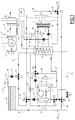
- the figure 1 illustrates a thermodynamic installation 1 that is designed to equip a building, such as an apartment building, an office building, a health building, a professional kitchen, a collective swimming pool, a sports building, an industrial building, a hotel or a house.
- a building such as an apartment building, an office building, a health building, a professional kitchen, a collective swimming pool, a sports building, an industrial building, a hotel or a house.
- the various equipment components of the installation 1 are symbolically represented, and the heat transfer fluid circuits and the water pipes connecting them are represented by continuous lines.
- Installation 1 makes it possible to manage, operate and optimize heat exchanges between the exterior and the interior of the building.
- the installation 1, which is integrated in the building, which is not shown in the figures, comprises a device 2 for extracting an air flow F1.
- the extraction device 2 for example, a controlled mechanical ventilation system of the building, sometimes abbreviated as "VMC", and allows the flow of F1 air to be extracted from inside the building, and particularly from the interior of several premises, offices or apartments building, for example using a network of ventilation ducts.
- VMC controlled mechanical ventilation system of the building
- the extraction device 2 makes it possible to transmit the flow of air F1 towards the outside of the building.
- the extraction device 2 forms a box with a compartment 5 and a compartment 6, preferably placed on the roof of the building or outside the latter, near one of its facades.
- the compartments 5 and 6 can be placed in attics, basements or technical premises of the building.
- the extraction device 2 comprises in particular an extraction mouth 3 sometimes called "stitching" placing the compartment 5 in communication with the interior of the building, via the aforementioned ductwork network.
- F1 air flow from the interior of the building is first admitted into the compartment 5 through the extraction mouth 3 at a temperature T3, which corresponds substantially to the temperature of the indoor air of the building.
- the extraction device 2 comprises a mechanical air extractor 4, which includes in the example a fan and which makes it possible to put this air in motion, creating a suction vacuum at the level of the exhaust mouth 3.
- the air extractor 4 is advantageously disposed within the compartment 5.
- the extraction device 2 also comprises a transfer port 7 of the air flow F1 from the compartment 5 to the compartment 6, the transfer port 7 being arranged at the outlet of the air extractor 4, and arranged in the wall of the compartment 5, so as to put the latter in communication with the compartment 6.
- the extraction device 2 also comprises an outlet mouth 8 of the F1 air flow, to allow the latter to escape to the outside of the compartment 6.
- the outlet mouth 8 communicates the interior of the latter with the outside of the building.
- the flow of air F1 is thus transferred from the inside of the building to the outside of the building via the extraction device 2.
- the flow of air F1 escapes from the outlet mouth 8 with a temperature T8.
- the compartments 5 and 6 can be separated by being connected by the transfer port 7, as illustrated, or instead form a one-piece assembly without separation, in which case the transfer port 7 is optional.
- the installation 1 also comprises a heat exchanger 9, allowing a heat exchange between the air flow F1, during its passage within the compartment 6, and a heat transfer fluid circulating in the exchanger 9.
- the latter is for example an exchanger called “finned battery” or “cyclonic” exchanger, and forms a battery exchange between the air flow air F1 and the heat transfer fluid circulating within it.
- the exchanger 9 is placed in the compartment 6 between the transfer port 7 and the outlet mouth 8 so that the air flow F1 passes through the exchanger 9 and thus delivers a portion of its embedded heat.
- the coolant is water, or at least a water-based liquid.
- the heat transfer fluid may be another type of liquid, for example refrigerant or a gas.
- the exchanger 9 thus preferably forms an air-water exchanger or alternatively air-gas exchanger.
- the heat transfer fluid enters the exchanger 9 at a temperature T9, and leaves at a temperature T10.
- the compartment 6 is also provided with an emergency mouth 16.
- the loop 16 is shown in the lower part of the compartment 6.
- the emergency mouth is located in the lateral part or above the compartment 6, and which allows the evacuation to the outside of fumes contained in the flow of air F1 in case of fire, to prevent them from crossing the exchanger 9.
- the installation 1 also comprises a storage tank 10 of the coolant.
- the term "storage tank” refers to a closed container of the tank or tank type for containing a predetermined volume of heat transfer fluid. Other means of storage of suitable heat transfer fluids can be implemented in place of the aforementioned storage tank.
- the storage tank 10 allows a substantially adiabatic storage of the heat transfer fluid. It is at least insulated, in order to keep the coolant at a temperature substantially constant T11, and for example in a range of -10 ° C to 90 ° C. By storing the heat transfer fluid, the storage tank 10 makes it possible to store a reserve of internal thermal energy, in the form of heat.
- the storage tank 10 has a unit capacity of between 0.3 m 3 and 3 m 3 . To overcome installation difficulties or a higher need for storage, several balloons can be installed. Phase change materials may also be used in the storage tank 10 to reduce the required volume of heat transfer fluid.
- the storage tank 10 is preferably placed remotely with respect to the extraction device 2. It is in particular placed within the building, for example in a suitable room, the technical room type, roof or cellar.
- the installation 1 comprises a heat transfer fluid circuit C1 which connects the heat exchanger 9 to the storage tank 10.
- This circuit C1 includes a line 11, which connects the storage tank 10 to the exchanger 9, to transport the stored heat transfer fluid in the storage tank 10 to the exchanger 9 for circulation within the exchanger 9.
- the circuit C1 also includes a line 12 for bringing the heat transfer fluid from the exchanger 9 to the storage tank. storage 10, after the heat transfer fluid has exchanged heat within the exchanger 9.
- the line 11 is advantageously connected in a low area of the storage tank 10, while the line 12 is preferably connected in the upper part of the storage tank 10.
- the circuit C1, and in particular the line 11 and the line 12, are presented in the form of pipes, or a network of pipes, heat transfer fluid.
- the circuit C1 includes a circulator 13 of the coolant, within the line 11, which is for example in the form of a pump adapted to circulate the heat transfer fluid in the circuit C1 in the direction indicated by the arrow FC1 on the figure 1 .
- the circulators of the installation 1 will be represented in the form of a circle in which is disposed an arrow FC1, FC2, FC3, FC4 and FC5, which gives the flow direction of heat transfer fluid imposed by the circulator concerned.
- the coolant is extracted from the storage tank 10, and then transported to the exchanger 9 to receive heat from the air flow F1 through this exchanger.
- the coolant is then returned to the storage tank 10 by the circuit C1 and the circulator 13 to be stored again.
- the heat transfer fluid stock included in the storage tank 10 thus forms a thermal energy reserve which is maintained by exchange of the heat transfer fluid with the air flow F1.
- the installation 1 is made to use this heat reserve in different ways as described below.
- the installation comprises an automatic control unit 100, for example an automaton, of its various components.
- the control unit 100 commands the circulator 13 to stop operating to interrupt the circulation of the coolant in the circuit C1 if the temperature T3 of the air flow F1 is less than or equal to the temperature T9 of the fluid inlet coolant in the heat exchanger 9, or temperature T11 of the heat transfer fluid stored in the storage tank 10, while maintaining the extraction device 2 running so that the building ventilation function is always provided.
- control unit 100 is connected to the various members of the installation by wired or even non-wired electrical connections.
- these links are not represented on the figure 1 .
- the installation 1 illustrated at figure 1 also comprises a heat pump 17, which forms an active means of heat energy transfer, and which requires to be supplied with energy, for example electrical, and / or from a fuel such as gas, to operate.
- the heat pump 17 is for example placed within the building, near the storage tank 10.
- the heat pump 17 comprises an exchange battery 19 which forms, for example, a condenser, and which is sometimes called the "hot side" of the heat pump 17.
- the heat pump 17 also comprises an exchange battery 21 formed by example by an evaporator of the heat pump 17, and sometimes called “cold side” of the heat pump 17.
- the heat pump 17 is designed to perform a heat transfer from the battery 21 to the battery 19, by thermodynamic work, for example by carrying out one or more thermodynamic cycles (s).
- the battery 19 is connected to a water network R1 of the building, this water being intended for sanitary use, and / or for heating purposes of the building, in particular by means of hot water radiators, or a fan coil, a ceiling cassette, an air handling unit.
- the water network R1 may also be intended to power a machine and thus constitute a water called "process".
- the water network R1 comprises a water supply pipe 31 coming for example from a collective water distribution network supplying the building.
- the inlet pipe 31 is connected to the exchange battery 19 so that this water of the collective network passes through the exchange battery 19.
- the water network R1 also comprises a pipe 33 for supplying water which is connected to the outlet of the exchange battery 19, this hot water being obtained by heating the water of the inlet pipe 31 within the exchange battery 19.
- the supply pipe 33 allows, for example, to feed a heating water distribution circuit, or a hot water preparation system.
- the installation 1 comprises a water circulator 35 for circulating the water to be heated within the water network R1.
- the heat pump 17 thus transfers heat to heat the water of the water network via the battery 19, the water of the water network passing within the battery 19 to be heated.
- the battery 21 is, in turn, connected to heat transfer fluid from the storage tank 10.
- the installation 1 comprises a coolant circuit C2, which connects the battery 21 to the storage tank 10.
- the circuit C2 comprises a line 25, which allows the fluid to be carried from the storage tank 10 to the storage tank 10. to the exchange battery 21, and a line 27, which makes it possible to bring the coolant cooled by the exchange battery 21 back to the storage tank 10.
- the circuit C2 comprises a circulator 29, of the same type as the circulator 13, to circulate the coolant within the circuit C2 in the direction indicated by the arrow FC2 on the figure 1 .
- the line 25 is advantageously connected in the upper part of the storage tank, while the line 27 is connected in the lower part of the latter.
- the installation 1 also comprises bridging lines 37 and 39 which are respectively connected bypassing the water network R1 and the circuit C2.
- the installation 1 also comprises modulating mixing valves 41, 43 associated respectively with the bridging lines 37, 39.
- the mixing valve 41 can progressively change between a configuration in which the coolant circulates in the exchange battery 19 from the line 31 or a line 59 which will be described below, and an alternative configuration in which the heat transfer fluid turns in a loop between the exchange battery 19 and the bridging line 37, under the action of the circulator 35.
- the presence of the mixing valve 41 and the bridging line 37 thus constitutes a safety device for protecting the heat pump 17 when the coolant is too cold.
- the modulating mixing valve 43 for its part, can evolve progressively between a configuration in which the heat transfer fluid circulates in the loop circuit C2 between the storage tank 10 and the exchange battery 21, and an alternative configuration in which the heat transfer fluid turns in a loop between the exchange battery 21 and the bridging line 39, under the action of the circulator 29.
- the presence of the mixing valve 43 and the bridging line 39 thus constitutes a safety device allowing protect the heat pump 17 when the coolant is too hot.
- the mixing valves 41 and 43 are actuated by solenoid valves, which are controlled by the automatic control unit 100.
- the presence of the valves 41 and 43, as well as that of the associated lines 37 and 39, is however optional.
- a line 20 connects the battery 19 to the storage tank 10, and is equipped with a passage valve 32 selectively permitting or prohibiting circulation by the circulator 35 of the heat transfer fluid directly from the battery to the pump. to the storage tank 10.
- the heat stored as heat transfer fluid in the storage tank 10 is used to heat the water of the water network R1 through the heat pump 17.
- the heat of the air stream F1 can be recovered at a temperature of moment different from that at which water is reheated for the water network R1.
- heat from the extraction device 2 can be accumulated for a long time, whereas the use of hot water in the building is generally carried out for a shorter duration, for example at the beginning and in the end of the day.
- the operation of the plant 1 is thus particularly optimized to the domestic hot water needs of the building and the possibilities of recovering heat from the F1 airflow.
- the installation 1 also comprises a solar collection system 45, for example of the atmospheric type or of the thermal type, which makes it possible to recover solar heat, for example by radiation from the sun on the solar collector system.
- the solar collection system 45 comprises a solar energy collection surface and an exchanger for transmitting the heat captured to the heat transfer fluid. It also includes, optionally, a heat transfer fluid storage tank not shown.
- the solar collection system 45 can also be divided into several separate sensing sections interconnected by a heat transfer fluid circuit.
- the solar collection system 45 is thus preferably placed on the roof of the building.
- the solar collection system 45 makes it possible to transmit the heat received either to the stored heat transfer fluid or to the supply water of the water network R1.
- the solar collector system 45 within the solar collection system 45, or its exchanger, can circulate either the heat transfer fluid, or water for the water network 33, optionally glycolated.
- the solar collector system 45 is provided with an input line 47 and an output line 49.
- the output line 49 is provided with a circulator 51 similar to the circulator previously described and making it possible to circulate either the fluid coolant, ie the above-mentioned water, in the direction indicated by the arrow FC3 on the figure 1 .
- the installation 1 comprises a passage valve 53 of the switching valves 55, 57 and 58 which are advantageously controlled by the automatic control unit 100.
- the automatic piloting unit 100 can decide, by controlling the valves 53, 55 , 57 and 58, which heat transfer fluid or water dispensing will be admitted within the solar collection system 45.
- a heat transfer fluid line 59 connects the storage tank 10, in the lower part of this last, the passage valve 53, which is itself connected to the input line 47 of the solar collector system 45.
- the passage valve 53 By opening the passage valve 53, the heat transfer fluid from the storage tank 10 is admitted within the solar collection system 45.
- the coolant progresses in the output line 49, passes through the pump 51, and reaches the switching valve 55, which is then in a configuration that allows you to the heat transfer fluid in a line 61 of the installation 1, the latter connecting the switching valve 55 to the storage tank 10, in the upper part of the latter.
- the lines 47, 49, 59 and 61 thus form a heat transfer fluid circuit C3 connecting the solar collection system 45 to the storage tank 10.
- the circulator 51 makes it possible to circulate the heat transfer fluid within this circuit C3.
- the water supply pipe 31 is connected to the switching valve 57, which allows to direct the water either towards the exchange battery 19 or towards the input line 47 of the solar collection system 45.
- the installation 1 comprises a transfer line 63, which connects the switching valve 55 to the switching valve 58.
- the switching valve 55 orients the water from the collection system solar 45 in the transfer line 63 to the switching valve 58.
- the switching valve 58 orients the water in the supply line 33.
- the received solar heat is directly transferred to the water of the water network R1 when the temperature T45 of the heat transfer fluid, at the end of its passage through the solar collection system 45, is greater than a temperature of set point to which it is desired to bring water from the supply line 33, the set temperature being a function of the subsequent use of this water.
- the control unit 100 controls the switching system 53 , 55, 57 and 58 to circulate the coolant within the solar collection system 45 so that solar heat is stored in the storage tank 10 for later use.
- control unit 100 controls the system. switching 53, 55, 57 and 58 so that neither the heat transfer fluid nor the water of the water network 31, 33 circulates within the solar collection system 45. In this case, the pump 51 is also stopped.
- the installation 1 makes it possible to implement a step k) of receiving solar heat by the solar collector system 45, followed by a step I) of transferring the solar heat received, selectively by means of the solar radiation system. 53, 55, 57, 58, or to the heat transfer fluid of the circuit C3 or to the dispensing water.
- the installation 1 makes it possible to implement a step m), which is performed only if the transfer of the solar heat is effected to the coolant of the circuit C3, involving a circulation FC3 of the coolant in the circuit C3, by means of the circulator 51, for storing the heat transfer fluid thus heated in the storage tank 10.
- the valves 57 and 58 illustrated are three-way valves. In alternatively, these valves 57 and 58 may each be replaced by two two-way valves, which offers more possibilities of adjustment: in particular, it is possible to supply the network R1 simultaneously heat transfer fluid from the battery 19 and solar collection system 45.
- the installation 1 comprises a heat exchanger 65 between the heat transfer fluid and wastewater, or water discharged by one or more machines, industrial water, or water heated by a cold unit, and in particular so-called “gray” waters or “valves” of a building evacuation network.
- This wastewater may for example be wastewater for sewer, and from washing machines, dishwashers, sinks, showers or toilets of the building.
- a heat transfer fluid circuit C4 connects the heat exchanger 65 to the storage tank 10 and includes a heat transfer fluid circulator 71 within the circuit C4, in the direction of the arrow FC4.
- the circuit C4 is formed by a line 67 which is connected to the storage tank 10 at the bottom of the latter, and to the exchanger 65.
- the circulator 71 is disposed on the line 67. to bring the heat transfer fluid to the storage tank 10, and thus connects the exchanger 65 and the storage tank 10, in the upper part thereof.
- the installation 1 thus makes it possible to carry out a step n) of circulating the coolant within a circuit C4 by means of the circulator 71, a step o) of heat exchange between the wastewater and the heat transfer fluid of the C4 circuit by means of the exchanger 65, and a storage step of heat transfer fluid and heated C4 circuit in the storage tank 10.
- the control unit 100 only starts the circulator 71 if the temperature T65 of the wastewater, referred to as the reference temperature, is higher than the temperature T11. Thus, in the hot water production process, the heat exchange between the wastewater and the coolant is performed only if the temperature T65 is greater than the temperature T11.
- the installation 1 further includes, within the storage tank 10, a heat exchanger 73.
- This exchanger 73 is for example in the form of a coaxial spiral coil coaxial with a vertical axis of the balloon, within the latter.
- the exchanger 73 is connected on the one hand to a water inlet pipe 75 of the water network R1, and on the other hand to a water supply pipe 77 of domestic water heating means, such as one or more gas boilers or water heating balloons, of the building.
- the water network R1 includes a first sub-network which includes the water inlet pipe 75 and the supply pipe 77, this first sub-network being connected via the supply line to a collective water source S, for example the water network of a city.
- the water from the water source S is said to be "cold", that is to say that it has not been heated, and that it is for example at the soil temperature.
- the water of the source S is preferably potable.
- the water network R1 then also includes a second sub-network, which forms a closed circuit, and which includes the inlet pipe 31, and the supply pipe 33 for the heating water supply intended to regulate the water supply. ambient temperature of the building interior.
- the collective water network advantageously provides the pressure necessary to circulate the water in the exchanger 73 and / or the supply line 77.
- an additional booster can be provided, for example by being placed upstream of the exchanger 73.
- the switching valve 79 needle the water of the inlet pipe 75 in the heat exchanger 73 only if the temperature T75 of this water coming from the water source S is lower than the temperature T11 of the heat transfer fluid stored in the storage tank 10.
- the installation 1 makes it possible to implement a step q) of heat exchange between the water of the water network R1 and the heat transfer fluid of the storage tank 10 by means of the exchanger 73.
- the installation 1 can implement a plurality of heat pumps 17, a plurality of storage tanks 10, a plurality of extraction devices 2, a plurality of solar collection systems 25 and a plurality of exchangers 9 and / or 65 and / or 73.
- the various circuits, circulators, switching valves, Bridging valves, or bypass valves, and the various lines, described above, are then adapted accordingly.
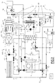
- the figure 2 shows a second embodiment of the previously described installation.
- the elements that are similar to the installation 1 have the same references and are not described again.
- the description of the following embodiments focuses on the differences that exist between the installation 1 of the figure 1 , and a 1000 installation illustrated at the figure 2 .
- the 1000 installation illustrated at figure 2 comprises in particular an extraction device 202, an exchanger 9, a heat pump 17, a storage tank 10, a circuit C1, a circuit C2, a solar collection system 45, a circuit C3, a heat exchanger 65, a circuit C4, an exchanger 73, and a water network R1.
- the extraction device 202 comprises, as the extraction device 2, an extraction mouth 3, an air extractor 4 and a compartment 5, in order to admit an air flow F1 coming from the inside. 5.
- the extraction device 202 also comprises a compartment 206 which is connected to the compartment 5 via the transfer port 7, the latter being located at the outlet of the air extractor 4 located in the compartment 5.
- the compartment 5 and the compartment 206 form a box.
- the compartment 206 is provided with an outlet mouth 8 through which the flow of air F1 is intended to escape the box.
- the exchanger 9 is located in the compartment 206 between the transfer port 7 and the outlet mouth 8. Thus the air flow F1 passes through the exchanger 9 before escaping through the outlet mouth 8 .
- the compartment 206 also comprises a high inlet mouth 215 of an air flow F 2, coming from the outside of the building, towards the interior of the compartment 206.
- the high inlet mouth 215 is arranged in such a way as to that the flow F2 passes through the exchanger 9 before escaping through the outlet mouth 8, just like the air flow F1.
- a fan 217 is optionally disposed in the compartment 206 facing the upper intake mouth 215 to suck the air flow F2 within the compartment 206.
- the air flow F2 mixes with the flow of air F1 before and / or during its circulation within the exchanger 9.
- the air flow F2 is admitted into the compartment 206 with a temperature T15 corresponding to the temperature of the outside air, that is to say the outside ambient temperature.
- the high inlet mouth 215 forms an air flow admission device F2 to allow heat exchange between this air flow and the heat transfer fluid, via the exchanger 9.
- the high inlet mouth 215 can evolve between a closed configuration, that is to say blocking preventing the passage respectively of the air flow F2, and an open configuration in which the passage of this flow is allowed.
- the fan 217 can be activated or deactivated simultaneously with the opening and closing of the high inlet mouth 215.
- the inlet mouth 215 and the fan 217 allow to allow or to prohibit the admission of the air flow F2 selectively, and therefore the heat exchange between this flow and the coolant in the exchanger 9. It is thus possible to use the air flow F2 to transfer calories to the heat transfer fluid.
- the control unit can order the admission of the airflow F2.
- the air flows F1 and F2 can be admitted at the same time within the exchanger 9 to bring more thermal energy to the heat transfer fluid.
- An emergency mouth 216 is located in the lower part of the compartment 206, as the emergency mouth 16 of the first embodiment, to allow for the evacuation of hot air or fire fumes.
- the embodiment of the figure 2 thus includes an air flow admission device F2 formed by the high inlet mouth 215 and the fan 217.
- the installation 1000 makes it possible to implement a step z) for comparing the temperature T3 of the air flow F1 with the temperature T11 of the heat transfer fluid stored in the storage tank 10 and at the temperature T15 of the outside air.
- the installation 1000 makes it possible to implement a step h) of admission of an air flow F2 coming from the outside of the building by means of the admission device 215, 217, and a step i) of exchange thermal between the air flow F2 and the coolant by means of the exchanger 9.
- the installation 1000 also makes it possible to implement a step j) of implementing steps h) and i) only if the temperature T15 of the outside air is greater than the temperature T11 of the heat transfer fluid stored in the storage tank. storage 10.
- the switching valve 55 of the first embodiment has been replaced by two simple valves 551 disposed respectively on the lines 61 and 63, to achieve the same function.
- the switching valve 79 has been replaced by two single valves 791 disposed respectively on the water inlet pipe 75 and the bypass pipe 81, to achieve the same function.
- the installation 1000 also includes a domestic water preheating tank 34 and a heating water tank 46.
- the preheating tank 34 and the heating water tank 46 are both supplied by the supply line 33. by means of two valves 50 and 52, controlled by the control unit 100 and which allow to selectively enable and prohibit the respective supply of the preheating tank 34 and the heating water tank 46 via the supply line 33. Depending on the needs and the temperature regimes, both valves can be opened at the same time.
- the preheating balloon 34 is itself connected to means 54 for producing domestic hot water, including, for example, a boiler, an electric heater, or a district heating network, or several of these elements, in order to bring them heat from the feed pipe 33 and help heat the water for sanitary use.
- the domestic hot water production means 54 are also supplied with water from the water source S via the supply line 77 or the bypass line 81, according to the state of the valves 791.
- the heating water tank 46 for its part, makes it possible to heat, or at least contribute to heating, the heating water intended to heat the interior air of the building, for example by means of water radiators or fan coil units.
- the installation 1000 also comprises a cooled water balloon 83, called “ice-cold”, and a heat transfer fluid circuit C5 connecting the cooled water tank 83 to the battery 21 and / or to the storage tank 10.
- cooled water or “chilled water” means water in liquid form, the temperature of which is between 0 ° C and 10 ° C, for example, or between 0 ° C and room temperature, and which is less than "Cold water” which comes from the source of water S.
- the cooled water of the cooled water tank 83 is, at least predominantly, intended to supply cooled water terminal transmitters, that is to say means for cooling the interior air of the building or process water, intended for example to be implemented in a salad wash basin or a plastic press.
- the circuit C5 is arranged so as to allow an exchange of thermal energy between the cooled water tank 83 and the coolant of the circuit C5, to allow cooling of the water contained in the water tank cooled 83.
- the coolant is water, it can be directly stored in the cooled water tank 83.
- the circuit C5 includes a line 90 of heat transfer fluid which is connected to the line 27 of the circuit C2, that is to say between the storage tank 10 and the battery 21.
- a switching valve 93 is provided to selectively switch the fluid coolant from the battery 21 is in the storage tank 10, or in the cooled water tank 83.
- the circuit C5 also includes a line 89 for returning the heat transfer fluid from the cooled water tank 83 to the line 25 of circuit C2.
- the coolant is circulated in the circuit C5 according to the arrow FC5 via the circulator 29.
- the switching valve 93 thus makes it possible to select which of the storage tank 10 or the cooled water tank 83 can be heat exchanged. with the battery 21.
- the line 25 is provided with a non-return device 42 disposed between the storage tank 10 and the branch of the line 89.
- the line 89 is in turn provided with a non-return device 44.
- the anti-return devices and back 42 and 44 make it possible to guarantee that the circulation of the heat-transfer fluid is effected according to the arrow FC2 or according to the arrow FC5 as a function of the orientation of the switching valve 93.
- the illustrated valve 93 is a three-way valve.
- each of the lines 89 and 90 may be equipped with a two-way valve, these two valves providing a function similar to that of the valve 93.
- the bypass line 38 includes a valve 36 which selectively allows or prohibits the flow of water therein.
- the installation 1000 also comprises a return line 40 connecting the storage tank 10 to the inlet pipe 31, between the switching valve 57 and the battery 19.
- the switching valve 93 directs the heat transfer fluid, coming from the battery 21, into the circuit C5, so that the coolant circulates between the battery 21 and the cooled water tank 83, and not the storage tank 10.
- the switching valve 58 is closed, and the valve 36 is open, so that water flows from the battery 19 to the storage tank 10 via the bypass line 38, and returns to the battery 19 via the return line 40.
- the excess heat produced by the heat pump 17 for cooling the cooled water tank is thus This excess heat can then be discharged, for example into the air stream F1 via the exchanger 9, by circulating the coolant in the circuit C1.
- the building needs both to be heated and to be cooled.
- the indoor air of buildings located on the north facade may require heating, while indoor air located in the south facade, in direct sunlight, may need to be cooled.
- a room for electronic or telecommunications equipment may need to be refreshed, while other premises in the same building may at the same time need to be heated.
- the coolant circulating in the battery 19 is sent to the preheating tank 34 by closing the valve 36 and opening the valve 58. In the same way, the coolant circulating in the battery 19 can be sent to the balloon heating water 46.
- FIGS. 3 and 4 respectively show extraction devices respectively belonging to a third and a fourth embodiments of the previously described installation.
- the elements that are similar to the elements of the extraction device 2 have the same references and are not described again.
- the description of the following embodiments focuses on the differences that exist between the extraction device 2 of the figure 1 , and those represented at Figures 3 and 4 .
- the figure 3 shows an extraction device 102 comprising the extraction mouth 3 which is formed in a single compartment 105 forming the box of the extraction device 102.
- the extraction device 102 also comprises the exchanger 9, which is disposed within the single compartment 105 to allow a heat exchange between the air flow F1, admitted by the exhaust port 3, and the heat transfer fluid of the circuit C1.
- the extraction device 102 comprises the air extractor 4 which is disposed within the single compartment 105, downstream of the exchanger 9, and which opens out on the outlet mouth 8.
- the extraction device 2 also comprises an inlet mouth 115, disposed at the top, or lateral, the single compartment 105, to admit the flow of air F2 downstream of the intake port 3 of the flow of air F1 within the single compartment 105 and upstream of the exchanger 9
- the inlet mouth 115 is thus disposed in the wall of the single compartment 105 between the extraction mouth 3 and the exchanger 9.
- the conditions of opening and closing of the inlet mouth 115 are preferably the same as those described above for the inlet mouth 215, the second embodiment of the figure 2 .
- the figure 4 illustrates an extraction device 302, which comprises a box, itself including the compartment 5, with the intake port 3, the air extractor 4 and the transfer port 7.
- the extraction device 302 comprises also a compartment 306 forming together with the compartment 5 the box of the extraction device 302.
- the compartment 306 is connected to the compartment 5 via the transfer port 7, and includes the exchanger 9, and the mouth of outlet 8 through which the flow of air F1 and the air flow F2 are intended to escape.
- the compartment 306 also comprises an intake fan 317 which is placed in an opening 315 for admitting the air flow F2 into the wall of the compartment 306. The air flow F2 is thus admitted via the fan 317. in the compartment 306 to then escape through the outlet mouth 8, after having passed through the exchanger 9.
- the compartment 306 also includes a partition wall 319 provided with an intermediate mouth 321.
- the intermediate partition 319 separates the compartment 306 in a part 306A which includes the transfer port 7, and in a part 306B which includes the exchanger 9, the outlet mouth 8 and the fan 317 for the admission of the air flow F2.
- the intermediate mouth 321 is designed to move between a configuration in which it allows the passage of the air flow F1 through the wall 319, and a configuration in which it prohibits the passage of this air flow.
- the portion 306A of the compartment 306 includes an intermediate outlet port 323.
- the intermediate outlet mouth 323 can be placed in the upper part of the compartment 306 and allows the escape of the flow F1 when the intermediate mouth 321 is closed.
- the part 306A also comprises an emergency opening 325, which can be placed in the lower part, for the evacuation of hot air or fire fumes coming from inside the building, in order to avoid that the latter reach the interchange 9.
- the mouth 325 is optional in this extraction device.
- the evacuation of the hot air or fire fumes can be through the mouth 323, when the latter is open and the mouth 321 is closed.
- the fan 317, and the mouths 315, 321 and 323 form in this case selection means selectively allowing to allow or prohibit the exchange of heat, via the exchanger 9, between on the one hand the flow of heat.
- F1 air and heat transfer fluid on the other hand between the air flow F2 and the heat transfer fluid.
- the air flow F1 or F2 of the highest temperature is then preferably chosen to provide heat to the heat transfer fluid via the exchanger 9.
- the mouths 315, 321 and 323 are configured so that neither the air flow F1 nor the air flow F2 reach the exchanger.
- the air flow F1 can be diverted via the intermediate outlet mouth 323 so as not to pass through the exchanger 9, without being interrupted, so that the ventilation of the building can be ensured continuously.
Landscapes
- Engineering & Computer Science (AREA)
- General Engineering & Computer Science (AREA)
- Physics & Mathematics (AREA)
- Thermal Sciences (AREA)
- Chemical & Material Sciences (AREA)
- Combustion & Propulsion (AREA)
- Mechanical Engineering (AREA)
- Sustainable Development (AREA)
- Sustainable Energy (AREA)
- Life Sciences & Earth Sciences (AREA)
- Heat-Pump Type And Storage Water Heaters (AREA)
- Steam Or Hot-Water Central Heating Systems (AREA)
- Central Heating Systems (AREA)
- Domestic Hot-Water Supply Systems And Details Of Heating Systems (AREA)
Applications Claiming Priority (1)
| Application Number | Priority Date | Filing Date | Title |
|---|---|---|---|
| FR1558284A FR3040771B1 (fr) | 2015-09-07 | 2015-09-07 | Installation et procede de production d'eau chaude associes |
Publications (2)
| Publication Number | Publication Date |
|---|---|
| EP3139100A1 true EP3139100A1 (de) | 2017-03-08 |
| EP3139100B1 EP3139100B1 (de) | 2021-05-26 |
Family
ID=54608770
Family Applications (1)
| Application Number | Title | Priority Date | Filing Date |
|---|---|---|---|
| EP16187459.9A Active EP3139100B1 (de) | 2015-09-07 | 2016-09-06 | Anlage und verfahren zur warmwassererzeugung |
Country Status (2)
| Country | Link |
|---|---|
| EP (1) | EP3139100B1 (de) |
| FR (1) | FR3040771B1 (de) |
Cited By (2)
| Publication number | Priority date | Publication date | Assignee | Title |
|---|---|---|---|---|
| RU2750084C1 (ru) * | 2019-04-12 | 2021-06-22 | Открытое акционерное общество "ИНСОЛАР-ИНВЕСТ" | Система теплонасосного теплохладоснабжения многоквартирных зданий |
| WO2024240598A1 (fr) * | 2023-05-23 | 2024-11-28 | Genvia | Installation et procédé de fourniture de vapeur industrielle valorisant une source de chaleur |
Citations (5)
| Publication number | Priority date | Publication date | Assignee | Title |
|---|---|---|---|---|
| GB2247072A (en) | 1990-06-13 | 1992-02-19 | Solmate Inc | Heating or cooling system |
| DE19900358A1 (de) * | 1999-01-07 | 2000-07-13 | Lueumel Nasdala & Beier Gmbh | Kombinierte Heizungs-/Lüftungsanlage, insbesondere für Niedrigenergiehäuser |
| FR2813117A1 (fr) * | 2000-08-21 | 2002-02-22 | Solartec | Procede et installation de chauffage a partir de l'energie solaire |
| NL2006250C2 (nl) * | 2011-02-18 | 2012-08-21 | M & O Techniek B V | Verwarming/koeling en warmwaterbereiding voor een gebouw. |
| FR2984997A1 (fr) | 2011-12-27 | 2013-06-28 | France Air | Installation de traitement d'air pour un batiment a usage collectif et procede de controle d'une telle installation |
-
2015
- 2015-09-07 FR FR1558284A patent/FR3040771B1/fr active Active
-
2016
- 2016-09-06 EP EP16187459.9A patent/EP3139100B1/de active Active
Patent Citations (5)
| Publication number | Priority date | Publication date | Assignee | Title |
|---|---|---|---|---|
| GB2247072A (en) | 1990-06-13 | 1992-02-19 | Solmate Inc | Heating or cooling system |
| DE19900358A1 (de) * | 1999-01-07 | 2000-07-13 | Lueumel Nasdala & Beier Gmbh | Kombinierte Heizungs-/Lüftungsanlage, insbesondere für Niedrigenergiehäuser |
| FR2813117A1 (fr) * | 2000-08-21 | 2002-02-22 | Solartec | Procede et installation de chauffage a partir de l'energie solaire |
| NL2006250C2 (nl) * | 2011-02-18 | 2012-08-21 | M & O Techniek B V | Verwarming/koeling en warmwaterbereiding voor een gebouw. |
| FR2984997A1 (fr) | 2011-12-27 | 2013-06-28 | France Air | Installation de traitement d'air pour un batiment a usage collectif et procede de controle d'une telle installation |
Cited By (3)
| Publication number | Priority date | Publication date | Assignee | Title |
|---|---|---|---|---|
| RU2750084C1 (ru) * | 2019-04-12 | 2021-06-22 | Открытое акционерное общество "ИНСОЛАР-ИНВЕСТ" | Система теплонасосного теплохладоснабжения многоквартирных зданий |
| WO2024240598A1 (fr) * | 2023-05-23 | 2024-11-28 | Genvia | Installation et procédé de fourniture de vapeur industrielle valorisant une source de chaleur |
| FR3149074A1 (fr) * | 2023-05-23 | 2024-11-29 | Genvia | Installation et procédé de fourniture de vapeur industrielle valorisant une source de chaleur |
Also Published As
| Publication number | Publication date |
|---|---|
| FR3040771B1 (fr) | 2019-12-20 |
| FR3040771A1 (fr) | 2017-03-10 |
| EP3139100B1 (de) | 2021-05-26 |
Similar Documents
| Publication | Publication Date | Title |
|---|---|---|
| EP2312227B1 (de) | Mechanisch gesteuerte reversible Zweistrom-Ventilationsanlage und Brauchwarmwassererzeugung | |
| EP2486331B1 (de) | Wärmespeichersystem | |
| EP2232155B1 (de) | Anlage zur bereitstellung von hygienischem warmwasser für mehrfamilienhäuser | |
| EP2191206A2 (de) | Erwärmungs- und kühlungsanlage mit einer wärmepumpe und einem an mehrere wärmesammlungs- und verteilungsleitungen gekoppelten kasten zur verteilung einer wärmeübertragungsflüssigkeit | |
| EP1992882B1 (de) | Anlage mit einer Weichenvorrichtung für Flüssigkeiten für deren alternativen Betrieb über Solar-, geothermische und Geosolarheizung | |
| WO2014044864A1 (fr) | Installation de chauffe-eau sanitaire à fonction de chauffage | |
| EP1978311A2 (de) | Von einer anderen Energiequelle unabhängiges und unabhängiges Sonnenheizungssystem | |
| EP3139100B1 (de) | Anlage und verfahren zur warmwassererzeugung | |
| FR2941517A1 (fr) | Installation immobiliere environnementale | |
| EP3910249B1 (de) | System zur erzeugung und verteilung von wärme und kälte und sein steuerungsverfahren | |
| EP2865951B1 (de) | Thermodynamische Anlage zur Erzeugung von Warmwasser | |
| FR3057651B1 (fr) | Installation de production d’eau chaude sanitaire pour une construction collective | |
| FR3088990A1 (fr) | Installation de chauffage | |
| CN107421139A (zh) | 一种能自动补水的无水箱式太阳能热水器的控制系统 | |
| FR2492955A1 (fr) | Chauffage central solaire a air d'un batiment | |
| WO2012150359A2 (fr) | Installation thermique | |
| CN101634491B (zh) | 太阳能、油气同步或交替及余热应用的热水系统和方法 | |
| FR3002027A1 (fr) | Chauffage solaire integral | |
| EP2734787B1 (de) | Verfahren zur warmawassererzeugung durch die verwendung von solarpanäle und mit einer vorrichtun zum schutz vor dem überhitzung | |
| FR2993348A1 (fr) | Dispositif d'optimisation des performances d'une pompe a chaleur en periode hivernale, par stockage d'energie en sol profond | |
| JP2019117015A (ja) | 給湯暖房システム | |
| FR3063132A1 (fr) | Systeme de gestion thermique d'air et de production d'eau chaude sanitaire pour un local | |
| EP3742062A1 (de) | Wärmetauscher mit doppelkreislauf | |
| EP2241828B1 (de) | verbesserte Warmwasseranlage mit variablem Volumen | |
| JP2011149642A (ja) | 太陽熱給湯装置 |
Legal Events
| Date | Code | Title | Description |
|---|---|---|---|
| PUAI | Public reference made under article 153(3) epc to a published international application that has entered the european phase |
Free format text: ORIGINAL CODE: 0009012 |
|
| STAA | Information on the status of an ep patent application or granted ep patent |
Free format text: STATUS: THE APPLICATION HAS BEEN PUBLISHED |
|
| AK | Designated contracting states |
Kind code of ref document: A1 Designated state(s): AL AT BE BG CH CY CZ DE DK EE ES FI FR GB GR HR HU IE IS IT LI LT LU LV MC MK MT NL NO PL PT RO RS SE SI SK SM TR |
|
| AX | Request for extension of the european patent |
Extension state: BA ME |
|
| STAA | Information on the status of an ep patent application or granted ep patent |
Free format text: STATUS: REQUEST FOR EXAMINATION WAS MADE |
|
| 17P | Request for examination filed |
Effective date: 20170809 |
|
| RBV | Designated contracting states (corrected) |
Designated state(s): AL AT BE BG CH CY CZ DE DK EE ES FI FR GB GR HR HU IE IS IT LI LT LU LV MC MK MT NL NO PL PT RO RS SE SI SK SM TR |
|
| STAA | Information on the status of an ep patent application or granted ep patent |
Free format text: STATUS: EXAMINATION IS IN PROGRESS |
|
| 17Q | First examination report despatched |
Effective date: 20191115 |
|
| GRAP | Despatch of communication of intention to grant a patent |
Free format text: ORIGINAL CODE: EPIDOSNIGR1 |
|
| STAA | Information on the status of an ep patent application or granted ep patent |
Free format text: STATUS: GRANT OF PATENT IS INTENDED |
|
| INTG | Intention to grant announced |
Effective date: 20210113 |
|
| GRAS | Grant fee paid |
Free format text: ORIGINAL CODE: EPIDOSNIGR3 |
|
| GRAA | (expected) grant |
Free format text: ORIGINAL CODE: 0009210 |
|
| STAA | Information on the status of an ep patent application or granted ep patent |
Free format text: STATUS: THE PATENT HAS BEEN GRANTED |
|
| AK | Designated contracting states |
Kind code of ref document: B1 Designated state(s): AL AT BE BG CH CY CZ DE DK EE ES FI FR GB GR HR HU IE IS IT LI LT LU LV MC MK MT NL NO PL PT RO RS SE SI SK SM TR |
|
| REG | Reference to a national code |
Ref country code: GB Ref legal event code: FG4D Free format text: NOT ENGLISH |
|
| REG | Reference to a national code |
Ref country code: CH Ref legal event code: EP |
|
| REG | Reference to a national code |
Ref country code: AT Ref legal event code: REF Ref document number: 1396602 Country of ref document: AT Kind code of ref document: T Effective date: 20210615 |
|
| REG | Reference to a national code |
Ref country code: DE Ref legal event code: R096 Ref document number: 602016058329 Country of ref document: DE |
|
| REG | Reference to a national code |
Ref country code: IE Ref legal event code: FG4D Free format text: LANGUAGE OF EP DOCUMENT: FRENCH |
|
| REG | Reference to a national code |
Ref country code: LT Ref legal event code: MG9D |
|
| REG | Reference to a national code |
Ref country code: AT Ref legal event code: MK05 Ref document number: 1396602 Country of ref document: AT Kind code of ref document: T Effective date: 20210526 |
|
| PG25 | Lapsed in a contracting state [announced via postgrant information from national office to epo] |
Ref country code: FI Free format text: LAPSE BECAUSE OF FAILURE TO SUBMIT A TRANSLATION OF THE DESCRIPTION OR TO PAY THE FEE WITHIN THE PRESCRIBED TIME-LIMIT Effective date: 20210526 Ref country code: LT Free format text: LAPSE BECAUSE OF FAILURE TO SUBMIT A TRANSLATION OF THE DESCRIPTION OR TO PAY THE FEE WITHIN THE PRESCRIBED TIME-LIMIT Effective date: 20210526 Ref country code: AT Free format text: LAPSE BECAUSE OF FAILURE TO SUBMIT A TRANSLATION OF THE DESCRIPTION OR TO PAY THE FEE WITHIN THE PRESCRIBED TIME-LIMIT Effective date: 20210526 Ref country code: BG Free format text: LAPSE BECAUSE OF FAILURE TO SUBMIT A TRANSLATION OF THE DESCRIPTION OR TO PAY THE FEE WITHIN THE PRESCRIBED TIME-LIMIT Effective date: 20210826 Ref country code: HR Free format text: LAPSE BECAUSE OF FAILURE TO SUBMIT A TRANSLATION OF THE DESCRIPTION OR TO PAY THE FEE WITHIN THE PRESCRIBED TIME-LIMIT Effective date: 20210526 |
|
| REG | Reference to a national code |
Ref country code: NL Ref legal event code: MP Effective date: 20210526 |
|
| PG25 | Lapsed in a contracting state [announced via postgrant information from national office to epo] |
Ref country code: GR Free format text: LAPSE BECAUSE OF FAILURE TO SUBMIT A TRANSLATION OF THE DESCRIPTION OR TO PAY THE FEE WITHIN THE PRESCRIBED TIME-LIMIT Effective date: 20210827 Ref country code: IS Free format text: LAPSE BECAUSE OF FAILURE TO SUBMIT A TRANSLATION OF THE DESCRIPTION OR TO PAY THE FEE WITHIN THE PRESCRIBED TIME-LIMIT Effective date: 20210926 Ref country code: LV Free format text: LAPSE BECAUSE OF FAILURE TO SUBMIT A TRANSLATION OF THE DESCRIPTION OR TO PAY THE FEE WITHIN THE PRESCRIBED TIME-LIMIT Effective date: 20210526 Ref country code: RS Free format text: LAPSE BECAUSE OF FAILURE TO SUBMIT A TRANSLATION OF THE DESCRIPTION OR TO PAY THE FEE WITHIN THE PRESCRIBED TIME-LIMIT Effective date: 20210526 Ref country code: SE Free format text: LAPSE BECAUSE OF FAILURE TO SUBMIT A TRANSLATION OF THE DESCRIPTION OR TO PAY THE FEE WITHIN THE PRESCRIBED TIME-LIMIT Effective date: 20210526 Ref country code: PT Free format text: LAPSE BECAUSE OF FAILURE TO SUBMIT A TRANSLATION OF THE DESCRIPTION OR TO PAY THE FEE WITHIN THE PRESCRIBED TIME-LIMIT Effective date: 20210927 Ref country code: PL Free format text: LAPSE BECAUSE OF FAILURE TO SUBMIT A TRANSLATION OF THE DESCRIPTION OR TO PAY THE FEE WITHIN THE PRESCRIBED TIME-LIMIT Effective date: 20210526 Ref country code: NO Free format text: LAPSE BECAUSE OF FAILURE TO SUBMIT A TRANSLATION OF THE DESCRIPTION OR TO PAY THE FEE WITHIN THE PRESCRIBED TIME-LIMIT Effective date: 20210826 |
|
| PG25 | Lapsed in a contracting state [announced via postgrant information from national office to epo] |
Ref country code: NL Free format text: LAPSE BECAUSE OF FAILURE TO SUBMIT A TRANSLATION OF THE DESCRIPTION OR TO PAY THE FEE WITHIN THE PRESCRIBED TIME-LIMIT Effective date: 20210526 |
|
| PG25 | Lapsed in a contracting state [announced via postgrant information from national office to epo] |
Ref country code: RO Free format text: LAPSE BECAUSE OF FAILURE TO SUBMIT A TRANSLATION OF THE DESCRIPTION OR TO PAY THE FEE WITHIN THE PRESCRIBED TIME-LIMIT Effective date: 20210526 Ref country code: ES Free format text: LAPSE BECAUSE OF FAILURE TO SUBMIT A TRANSLATION OF THE DESCRIPTION OR TO PAY THE FEE WITHIN THE PRESCRIBED TIME-LIMIT Effective date: 20210526 Ref country code: SM Free format text: LAPSE BECAUSE OF FAILURE TO SUBMIT A TRANSLATION OF THE DESCRIPTION OR TO PAY THE FEE WITHIN THE PRESCRIBED TIME-LIMIT Effective date: 20210526 Ref country code: SK Free format text: LAPSE BECAUSE OF FAILURE TO SUBMIT A TRANSLATION OF THE DESCRIPTION OR TO PAY THE FEE WITHIN THE PRESCRIBED TIME-LIMIT Effective date: 20210526 Ref country code: DK Free format text: LAPSE BECAUSE OF FAILURE TO SUBMIT A TRANSLATION OF THE DESCRIPTION OR TO PAY THE FEE WITHIN THE PRESCRIBED TIME-LIMIT Effective date: 20210526 Ref country code: EE Free format text: LAPSE BECAUSE OF FAILURE TO SUBMIT A TRANSLATION OF THE DESCRIPTION OR TO PAY THE FEE WITHIN THE PRESCRIBED TIME-LIMIT Effective date: 20210526 Ref country code: CZ Free format text: LAPSE BECAUSE OF FAILURE TO SUBMIT A TRANSLATION OF THE DESCRIPTION OR TO PAY THE FEE WITHIN THE PRESCRIBED TIME-LIMIT Effective date: 20210526 |
|
| REG | Reference to a national code |
Ref country code: DE Ref legal event code: R097 Ref document number: 602016058329 Country of ref document: DE |
|
| REG | Reference to a national code |
Ref country code: DE Ref legal event code: R119 Ref document number: 602016058329 Country of ref document: DE |
|
| PLBE | No opposition filed within time limit |
Free format text: ORIGINAL CODE: 0009261 |
|
| STAA | Information on the status of an ep patent application or granted ep patent |
Free format text: STATUS: NO OPPOSITION FILED WITHIN TIME LIMIT |
|
| 26N | No opposition filed |
Effective date: 20220301 |
|
| GBPC | Gb: european patent ceased through non-payment of renewal fee |
Effective date: 20210906 |
|
| PG25 | Lapsed in a contracting state [announced via postgrant information from national office to epo] |
Ref country code: IS Free format text: LAPSE BECAUSE OF FAILURE TO SUBMIT A TRANSLATION OF THE DESCRIPTION OR TO PAY THE FEE WITHIN THE PRESCRIBED TIME-LIMIT Effective date: 20210926 Ref country code: MC Free format text: LAPSE BECAUSE OF FAILURE TO SUBMIT A TRANSLATION OF THE DESCRIPTION OR TO PAY THE FEE WITHIN THE PRESCRIBED TIME-LIMIT Effective date: 20210526 Ref country code: AL Free format text: LAPSE BECAUSE OF FAILURE TO SUBMIT A TRANSLATION OF THE DESCRIPTION OR TO PAY THE FEE WITHIN THE PRESCRIBED TIME-LIMIT Effective date: 20210526 |
|
| PG25 | Lapsed in a contracting state [announced via postgrant information from national office to epo] |
Ref country code: IT Free format text: LAPSE BECAUSE OF FAILURE TO SUBMIT A TRANSLATION OF THE DESCRIPTION OR TO PAY THE FEE WITHIN THE PRESCRIBED TIME-LIMIT Effective date: 20210526 Ref country code: IE Free format text: LAPSE BECAUSE OF NON-PAYMENT OF DUE FEES Effective date: 20210906 Ref country code: GB Free format text: LAPSE BECAUSE OF NON-PAYMENT OF DUE FEES Effective date: 20210906 Ref country code: DE Free format text: LAPSE BECAUSE OF NON-PAYMENT OF DUE FEES Effective date: 20220401 |
|
| PG25 | Lapsed in a contracting state [announced via postgrant information from national office to epo] |
Ref country code: HU Free format text: LAPSE BECAUSE OF FAILURE TO SUBMIT A TRANSLATION OF THE DESCRIPTION OR TO PAY THE FEE WITHIN THE PRESCRIBED TIME-LIMIT; INVALID AB INITIO Effective date: 20160906 |
|
| PG25 | Lapsed in a contracting state [announced via postgrant information from national office to epo] |
Ref country code: CY Free format text: LAPSE BECAUSE OF FAILURE TO SUBMIT A TRANSLATION OF THE DESCRIPTION OR TO PAY THE FEE WITHIN THE PRESCRIBED TIME-LIMIT Effective date: 20210526 |
|
| PG25 | Lapsed in a contracting state [announced via postgrant information from national office to epo] |
Ref country code: MK Free format text: LAPSE BECAUSE OF FAILURE TO SUBMIT A TRANSLATION OF THE DESCRIPTION OR TO PAY THE FEE WITHIN THE PRESCRIBED TIME-LIMIT Effective date: 20210526 |
|
| PG25 | Lapsed in a contracting state [announced via postgrant information from national office to epo] |
Ref country code: TR Free format text: LAPSE BECAUSE OF FAILURE TO SUBMIT A TRANSLATION OF THE DESCRIPTION OR TO PAY THE FEE WITHIN THE PRESCRIBED TIME-LIMIT Effective date: 20210526 |
|
| PG25 | Lapsed in a contracting state [announced via postgrant information from national office to epo] |
Ref country code: MT Free format text: LAPSE BECAUSE OF FAILURE TO SUBMIT A TRANSLATION OF THE DESCRIPTION OR TO PAY THE FEE WITHIN THE PRESCRIBED TIME-LIMIT Effective date: 20210526 |
|
| PGFP | Annual fee paid to national office [announced via postgrant information from national office to epo] |
Ref country code: LU Payment date: 20250828 Year of fee payment: 10 |
|
| REG | Reference to a national code |
Ref country code: CH Ref legal event code: U11 Free format text: ST27 STATUS EVENT CODE: U-0-0-U10-U11 (AS PROVIDED BY THE NATIONAL OFFICE) Effective date: 20251001 |
|
| PGFP | Annual fee paid to national office [announced via postgrant information from national office to epo] |
Ref country code: BE Payment date: 20250919 Year of fee payment: 10 |
|
| PGFP | Annual fee paid to national office [announced via postgrant information from national office to epo] |
Ref country code: FR Payment date: 20250812 Year of fee payment: 10 |
|
| REG | Reference to a national code |
Ref country code: CH Ref legal event code: R18 Free format text: ST27 STATUS EVENT CODE: U-0-0-R10-R18 (AS PROVIDED BY THE NATIONAL OFFICE) Effective date: 20260106 |
|
| PGFP | Annual fee paid to national office [announced via postgrant information from national office to epo] |
Ref country code: CH Payment date: 20251001 Year of fee payment: 10 |