EP3140019B1 - Base plate for supporting interlocking building bricks - Google Patents
Base plate for supporting interlocking building bricks Download PDFInfo
- Publication number
- EP3140019B1 EP3140019B1 EP15789761.2A EP15789761A EP3140019B1 EP 3140019 B1 EP3140019 B1 EP 3140019B1 EP 15789761 A EP15789761 A EP 15789761A EP 3140019 B1 EP3140019 B1 EP 3140019B1
- Authority
- EP
- European Patent Office
- Prior art keywords
- base plate
- ledge
- base plates
- node
- cylindrical wall
- Prior art date
- Legal status (The legal status is an assumption and is not a legal conclusion. Google has not performed a legal analysis and makes no representation as to the accuracy of the status listed.)
- Active
Links
Images


Classifications
-
- A—HUMAN NECESSITIES
- A63—SPORTS; GAMES; AMUSEMENTS
- A63H—TOYS, e.g. TOPS, DOLLS, HOOPS OR BUILDING BLOCKS
- A63H33/00—Other toys
- A63H33/04—Building blocks, strips, or similar building parts
- A63H33/06—Building blocks, strips, or similar building parts to be assembled without the use of additional elements
- A63H33/08—Building blocks, strips, or similar building parts to be assembled without the use of additional elements provided with complementary holes, grooves, or protuberances, e.g. dovetails
-
- A—HUMAN NECESSITIES
- A63—SPORTS; GAMES; AMUSEMENTS
- A63H—TOYS, e.g. TOPS, DOLLS, HOOPS OR BUILDING BLOCKS
- A63H33/00—Other toys
- A63H33/04—Building blocks, strips, or similar building parts
-
- A—HUMAN NECESSITIES
- A63—SPORTS; GAMES; AMUSEMENTS
- A63H—TOYS, e.g. TOPS, DOLLS, HOOPS OR BUILDING BLOCKS
- A63H33/00—Other toys
- A63H33/04—Building blocks, strips, or similar building parts
- A63H33/06—Building blocks, strips, or similar building parts to be assembled without the use of additional elements
- A63H33/08—Building blocks, strips, or similar building parts to be assembled without the use of additional elements provided with complementary holes, grooves, or protuberances, e.g. dovetails
- A63H33/086—Building blocks, strips, or similar building parts to be assembled without the use of additional elements provided with complementary holes, grooves, or protuberances, e.g. dovetails with primary projections fitting by friction in complementary spaces between secondary projections, e.g. sidewalls
-
- A—HUMAN NECESSITIES
- A63—SPORTS; GAMES; AMUSEMENTS
- A63H—TOYS, e.g. TOPS, DOLLS, HOOPS OR BUILDING BLOCKS
- A63H33/00—Other toys
- A63H33/04—Building blocks, strips, or similar building parts
- A63H33/14—Building blocks, strips, or similar building parts specially adapted to be assembled by adhesive or cement
-
- B—PERFORMING OPERATIONS; TRANSPORTING
- B41—PRINTING; LINING MACHINES; TYPEWRITERS; STAMPS
- B41M—PRINTING, DUPLICATING, MARKING, OR COPYING PROCESSES; COLOUR PRINTING
- B41M5/00—Duplicating or marking methods; Sheet materials for use therein
- B41M5/0041—Digital printing on surfaces other than ordinary paper
- B41M5/0064—Digital printing on surfaces other than ordinary paper on plastics, horn, rubber, or other organic polymers
-
- B—PERFORMING OPERATIONS; TRANSPORTING
- B41—PRINTING; LINING MACHINES; TYPEWRITERS; STAMPS
- B41J—TYPEWRITERS; SELECTIVE PRINTING MECHANISMS, i.e. MECHANISMS PRINTING OTHERWISE THAN FROM A FORME; CORRECTION OF TYPOGRAPHICAL ERRORS
- B41J11/00—Devices or arrangements of selective printing mechanisms, e.g. ink-jet printers or thermal printers, for supporting or handling copy material in sheet or web form
- B41J11/0015—Devices or arrangements of selective printing mechanisms, e.g. ink-jet printers or thermal printers, for supporting or handling copy material in sheet or web form for treating before, during or after printing or for uniform coating or laminating the copy material before or after printing
- B41J11/002—Curing or drying the ink on the copy materials, e.g. by heating or irradiating
- B41J11/0021—Curing or drying the ink on the copy materials, e.g. by heating or irradiating using irradiation
- B41J11/00214—Curing or drying the ink on the copy materials, e.g. by heating or irradiating using irradiation using UV radiation
-
- B—PERFORMING OPERATIONS; TRANSPORTING
- B41—PRINTING; LINING MACHINES; TYPEWRITERS; STAMPS
- B41J—TYPEWRITERS; SELECTIVE PRINTING MECHANISMS, i.e. MECHANISMS PRINTING OTHERWISE THAN FROM A FORME; CORRECTION OF TYPOGRAPHICAL ERRORS
- B41J3/00—Typewriters or selective printing or marking mechanisms characterised by the purpose for which they are constructed
- B41J3/407—Typewriters or selective printing or marking mechanisms characterised by the purpose for which they are constructed for marking on special material
- B41J3/4073—Printing on three-dimensional objects not being in sheet or web form, e.g. spherical or cubic objects
-
- B—PERFORMING OPERATIONS; TRANSPORTING
- B41—PRINTING; LINING MACHINES; TYPEWRITERS; STAMPS
- B41M—PRINTING, DUPLICATING, MARKING, OR COPYING PROCESSES; COLOUR PRINTING
- B41M5/00—Duplicating or marking methods; Sheet materials for use therein
- B41M5/0041—Digital printing on surfaces other than ordinary paper
- B41M5/0047—Digital printing on surfaces other than ordinary paper by ink-jet printing
-
- B—PERFORMING OPERATIONS; TRANSPORTING
- B41—PRINTING; LINING MACHINES; TYPEWRITERS; STAMPS
- B41M—PRINTING, DUPLICATING, MARKING, OR COPYING PROCESSES; COLOUR PRINTING
- B41M5/00—Duplicating or marking methods; Sheet materials for use therein
- B41M5/0082—Digital printing on bodies of particular shapes
- B41M5/0088—Digital printing on bodies of particular shapes by ink-jet printing
Definitions
- the present invention relates to products and methods in the field of interlocking building bricks.
- the present invention is directed to base plates for use with interlocking building bricks, methods of manufacturing base plates, and methods of applying custom colors and images to base plates.
- LEGO brick with projecting studs on one side and recessed tubes on the other, offers unlimited building possibilities. Any number of LEGO bricks may be joined with one another to construct increasingly complex structures.
- base plates are what are known in the art as base plates.
- Base plates are relatively flat, planar sheets having a number of studs on one side for attaining an interlocking engagement with the tubes of LEGO bricks. Owing to their relatively flat, planar form, base plates are able to provide increased stability to LEGO brick constructions that are engaged with the studs of the base plate.
- conventional base plates are generally mass-produced in only limited sizes of fixed dimensions - such as, for example, plastic sheets of 20.32cm (8 inches) by 20.32cm (8 inches), or 38.10cm (15 inches) by 38.10cm (15 inches).
- the LEGO brick market has not been served by having building base plates larger than 38.10cm (15 inches) in size. This restricts the utility of conventional base plates. For example, consumers wishing to assemble relatively large LEGO brick constructions are required to utilize multiple base plates to achieve adequate support for the construction.
- conventional base plates lack any structure for directly interlinking or combining separate base plates with one another, the consumer is required to join the separate base plates by use of an extra engagement structure - such as by adhering the separate plates to one another, or to a common backing, via nails, staples, or glue.
- an extra engagement structure such as by adhering the separate plates to one another, or to a common backing, via nails, staples, or glue.
- conventional base plates are often easily deformed and damaged.
- base plates having a variety of sizes other than those conventionally available; including sizes having at least one dimension of more than 38.10cm (15 inches).
- base plates of more robust and durable construction There remains a further need in the art for a method of customizing the appearance of base plates; including a method of applying custom colors and images to a post-production base plate in a durable, scratch-resistant manner.
- the US 3 895 456 A discloses a composition assembly comprising of constructional elements for forming toys, educational games, articles for window dressing, furnishings and decoration.
- a flat base has a top surface with a plurality of protrusions or members projecting from the top surface, which members can be of a right circular frusto-conical shape.
- the present invention is directed to a base plate for supporting a plurality of interlocking building bricks, comprising a planar sheet having a top surface and a bottom surface, with a plurality of nodes projecting from the top surface, wherein the plurality of nodes comprises a node having a vertical cylindrical wall and a horizontal top wall, the vertical cylindrical wall tapering along its vertical height, and the node comprises a bevel extending around a circumference of the node at an edge where the vertical cylindrical wall transitions to the horizontal top wall, wherein the bevel has a radius of curvature ranging from about 0.03810cm to about 0.04318cm, and the taper of the vertical cylinder wall has a taper angle ranging from about 2° to about 4°, as measured relative to an axis extending perpendicular to top surface of the planar sheet.
- the bevel extending around the circumference of the node is a rounded bevel.
- the vertical cylindrical wall has a diameter that tapers along the vertical height of the vertical cylindrical wall; the diameter of the vertical cylindrical wall tapering continuously from a base of the node to the bevel extending around the circumference of the node.
- the taper of the vertical cylindrical wall has a taper angle ranging from about 2° to about 4°, which is preferably 3°, as measured relative to an axis extending perpendicular to top surface of the planar sheet.
- the planar sheet includes a first interlocking mechanism extending along a first peripheral edge, and a second interlocking mechanism extending along a second peripheral edge, the first and second interlocking mechanisms being adapted to mate with one another such that the base plate is capable of mating with another base plate of the same construction.
- the interlocking mechanism along the first peripheral edge is in the form of a two-tier annular ledge having a top ledge and a bottom ledge, the top ledge extending further horizontally from the planar sheet than the bottom ledge; and the interlocking mechanism along the second peripheral edge is also in the form of a two-tier annular ledge including a top ledge and a bottom ledge, the bottom ledge extending further horizontally from the planar sheet than the top ledge.
- the present invention is directed to base plates for use with interlocking building bricks, methods of manufacturing base plates, and methods of applying custom colors and images to base plates. More particularly, the present invention relates to base plates, or "tiles", for use with interlocking building bricks in the plastics toy market; and methods of manufacturing such base plates.
- the base plates may be engineered for mounting in various ways, such as on floors, walls, and other substrates.
- the base plates may also be provided with interlocking mechanisms, and an engineered backing for a stronger more durable design.
- the present invention also relates to methods of printing colors and images onto post-production base plates with an ultraviolet (UV) light printer.
- UV ultraviolet
- post-production base plates are to be understood as referring to base plates that have been manufactured to a point where studs (or the inventive nodes) have been formed to project from a surface of the base plate.
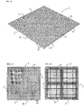
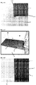
- FIG. 1 shows one example of a base plate 1 according to the present invention.
- the base plate 1 in this example is a relatively flat, planar sheet 2 measuring 30.48cm (12 inches) by 30.48cm (12 inches).
- On a top surface 3 of the base plate 1, as shown in FIGS. 1 -2 there is provided a plurality of nodes 10.
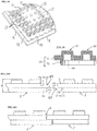
- On a bottom surface 5 of the base plate 1, as shown in FIG. 3 there is provided a plurality of cavities 11 (corresponding to the raised nodes 10 on the top surface 3); a plurality of barrels 13; and a number of reinforcing ridges 15/17.
- the base plate 1 has a height 4, as measured from a bottom of the back surface to a top of a node 10, of about 0.577cm (0.227 inches).
- Base plates according to the present invention may be manufactured through use of a Computer Aided Design (CAD) program for modeling the desired shape and dimensions of a target base plate 1.
- CAD Computer Aided Design
- a CAD program may be used to generate an injection molding model for a base plate 1; and a die head may then be fabricated to the specifications of the CAD-generated model from a material suitable for use in injection molding, such as steel, aluminum and the like.
- the fabricated die head is then placed in an injection molding machine, which may pressure feed a heated quantity of molding material to the die head via multiple gate injection.
- the heated material may be high-impact polystyrene, or any other material suitable for injection molding.
- the injection molding machine may include a local supply source holding feed material for generating the molding material (e.g. , a supply container of polystyrene resin pellets), and a control unit for subjecting the feed material to suitable temperature, pressure, and volume conditions for compressing the feed material to generate the molding material, and then feeding that mold material to completely fill the die head.
- the die head is cooled until the mold material hardens into the base plate shape defined by the die head; and a molded base plate is then ejected from the die head and sent for post-production processing.
- the base plate 1 has a 38 x 38 node matrix, providing a total of 1 ,444 nodes 10.
- FIGS. 4-7 show an example of a node 10.
- the node 10 has a diameter 101 measuring 0.495cm (0.195 inches) and a height 102 measuring 0.191cm (0.075 inches); and is provided with a tapered and beveled construction.
- the diameter 101 is measured at the base of the node 10; and the height 102 is measured from the base to the horizontal top wall 103 of the node 10.
- nodes 10 within the node matrix are positioned such that the central vertical axes 104 of adjacent nodes 10 are separated by a distance 105, which in the illustrated example measures about 0.8cm (0.315 inches).
- the taper of the node 10 is characterized by a vertical cylindrical wall 106 that continuously decreases in diameter along its vertical height 102, as defined by a taper angle 107 between the cylindrical wall 106 and an axis 108 extending perpendicular to the top surface 3 of the base plate 1.
- the taper angle 107 ranges from about 2° to about 4°; and is preferably about 3°. In the instance of an injection molded node 10, the taper angle 107 may be referred to as a draft angle.
- a rounded bevel 109 extends around the circumference of the top edge of the node 10, such that there is a curved transition between the horizontal top wall 103 and the vertical cylindrical wall 106.
- the rounded bevel 109 has a radius of curvature ranging from about 0.03810cm (.015 inch) to about 0.04318cm (.017 inch); and is preferably about 0.04064cm (.016 inch).
- LEGO bricks and DUPLO bricks (as sold by The LEGO Group, under the trademark DUPLO) have slightly different sizing.
- conventional base plates that are suitable for use with LEGO bricks may not provide the desired degree of support when used with DUPLO bricks, and vice versa. Therefore, consumers often purchase separate base plates for their LEGO bricks and DUPLO bricks, and are not able to directly engage the two separate brick types to a single base plate.
- the base plates 1, employing the node 10 are able to directly engage both LEGO bricks and DUPLO bricks with satisfactory support.
- the ability of the node 10 in achieving satisfactory engagements with varying types of interlocking building bricks is due to a synergy between the rounded bevel 109 and the tapered cylindrical wall 106. It is thought the rounded bevel 109 facilitates an initial engagement of the node 10 with the differently sizes tubes of varying types of interlocking building bricks. It is considered that the tapered cylindrical wall 106 then facilitates a further pressing of the initially engaged brick into yet further engagement with the base plate 1 with a concurrent increase in frictional forces between the nodes 10 and the tubes of the brick (owing to the increase in node diameter at points closer to the node base).
- the increasing diameter of the node 10 allows different brick types to each attain satisfactory engagement by permitting different brick types to reach optimal engagement points at different points along the height 102 of the tapering nodes 10; and/or by generating a slight deformation in the engaging walls of the different brick types via a wedging force incurred as the brick is pressed against the tapered nodes 10.
- FIGS. 3 and 8 When viewing the bottom surface 5 of the base plate 1, as shown in FIGS. 3 and 8 , there may be seen a plurality of cavities 11 (each cavity corresponding with a node 10 that projects from the top surface 3). A number of the cavities 11 are encircled by a barrel 13. Though the illustrated example shows barrels 13 being provided at only select cavities 11 (e.g. , presenting a cross pattern on the bottom surface 5 in the illustrated example), it is to be understood that any number of barrels 13 may be provided - including fewer or more barrels 13, and including an arrangement where each cavity 11 is encircled by a barrel 13.
- the barrels 13 on the bottom surface 5 of the base plate 1 are sized and shaped for mating engagement with the studs on conventional LEGO bricks.
- the base plate 1 may itself be used as an interlocking building brick in assembling a multi-tiered construction, such as a construction simulating an office building, a parking garage, etc.
- the barrels 13 are also adequately sized and shaped to mate with the nodes 10, such that a base plate 1 may be stacked atop another base plate 1.
- inclusion of the barrels 13 also provides the base plate 1 with increased rigidity and durability.
- a network of ridges 15/17 project from the bottom surface 5 of the base plate 1.
- the ridge network includes perimeter ridges 15 extending along the perimeter of the bottom surface 5; and a number of interior ridges 17 arranged in a square grid extending along interior regions of the bottom surface 5.
- the ridge network may take other shapes; and/or include fewer or more ridges ⁇ e.g . , diagonally oriented interior ridges arranged in truss-like formation within the square grid of interior ridges 17). Inclusion of the ridge network also provides the base plate 1 with increased rigidity and durability.
- the barrels 13 and the ridge network project an equal distance from the bottom surface 5 of the base plate 1.
- the barrels 13 and the ridge network project 0.196cm (0.077 inches) from the bottom surface 5, as shown in FIG. 9 .
- the inclusion of barrels 13 and a ridge network that project to an equal distance enables the base plate 1 to achieve not only enhanced stability for supporting LEGO brick constructions that are engaged via nodes 10, but also enhanced durability in withstanding increased applications of force, such as the weight of a grown adult walking and standing on the base plate 1.
- an interlocking mechanism 30 in the form of a two-tiered annular ledge, extends around the perimeter of the base plate 1.
- the two-tiered form of the interlocking mechanism 30 includes a top ledge 31 and a bottom ledge 32 that extend to different lengths in the horizontal direction of the base plate 1.
- both the top and bottom ledges 31/32 have a height 33 of 0.193cm (0.076 inches); with the further extending ledge projecting, in both instances, a horizontal distance 34 of 0,254cm (0.1 inches) beyond the other corresponding ledge in the two-tiered form at that respective peripheral edge.
- the further projecting ledge (be it the top ledge edge 31 or the bottom ledge 32) may be referred to as a male member; and the recessed, or lesser projecting ledge (be it the top ledge edge 31 or the bottom ledge 32) may be referred to as a female member.
- the interlocking mechanism 30 facilitates alignment of two separate base plates 1 in a manner that enhances stability and durability of the combined base plates, while also reducing the appearance of a seam 6 between the two base plates. This may be achieved, as shown in FIG. 11 , by aligning a peripheral edge 8/9 of the first base plate 1, having a further projecting bottom ledge 32, to correspond with a mating peripheral edge 6/7 of the second base plate 1 , having a further projecting top ledge 31.
- the further extending bottom ledge 32 of the first base plate is positioned to provide structural support to the further extending top ledge 31 of the second base plate, while at the same time presenting a minimal appearance of the seam 6 between the two base plates.
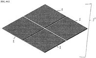
- a user may align multiple base plates 1 to provide a larger support area. For example, as shown in FIG. 12 , four separate base plates 1, each measuring 30.48cm (12 inches) by 30.48cm (12 inches), may be aligned with one another via the interlocking mechanisms 30 to yield a larger support area measuring 60.96cm (24 inches) by 60.96cm (24 inches).
- the interlocking mechanisms 30 may be used to releasably align any number of based plates 1 in this manner; such that multiple base plates 1 may be aligned for use in unison, though stored individually.
- the interlocking mechanism 30 may be used to facilitate a permanent joining of multiple base plates 1 to produce a single composite base plate 1' of larger dimensions.
- One exemplary method of constructing a composite base plate 1', which is itself composed of multiple post-production base plates 1, will now be explained.
- the target size for a composite base plate 1' is identified and a suitable number of post-production base plates 1 are obtained to achieve those necessary dimensions to yield the target size. For example, if seeking to construct a composite base plate 1' measuring 60.96cm (24 inches) by 121.92cm (48 inches), there may be obtained eight post-production base plates 1a-1h that each separately measure 30.48cm (12 inches) by 30.48cm (12 inches); and which will serve as "component base plates 1" for assembly of the composite base plate 1'. A backing board 40 of corresponding dimensions is then obtained.
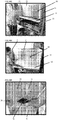
- the backing board 40 is preferably a substrate of suitable composition, such as a medium density fiberboard (MDF), a honeycomb paper backing, or a Komatex polyvinyl chloride sheet. As shown in FIG. 13 , the backing board 40 is positioned in a forming container 50 having three walls 51 and a base surface 55; the base surface 55 being made to have dimensions sufficiently sized to receive the backing board 40 in a flat orientation thereon.
- MDF medium density fiberboard
- honeycomb paper backing honeycomb paper backing
- Komatex polyvinyl chloride sheet a Komatex polyvinyl chloride sheet.
- the backing board 40 is placed flatly on the base surface 55 of the forming container 50 such that at least edges of the backing board 40 are flush with at least two walls 51 of the forming container 50, as shown in FIG. 14 .
- a quantity of bonding material is applied along the perimeter of the backing board 40.
- a first component base plate 1a is selected and a quantity of bonding material is applied along the perimeter ridge 15 on the bottom surface 5 thereof.
- the first component base plate 1a is then firmly pressed flat against the backing board 40, with two peripheral edges of the first component base plate 1a placed flush against two walls 51 of the forming container 50, and with the bonding material along the bottom surface 5 of the first component base plate 1a coming into contact with bonding material along the perimeter of the backing board 40, as shown in FIG. 15 .
- the first component base plate 1a is placed on the backing board 40 in such an orientation that the two peripheral edges 6/7 having the further extending top ledge 31 are placed flush against the two walls 51 of the forming container 50, while the two perimeter edges 8/9 having the further extending bottom ledge 32 are exposed, as shown in FIG. 16 .
- a second component base plate 1b is selected and a quantity of bonding material is applied along the perimeter ridge 15 on the bottom surface 5 thereof.
- the second component base plate 1b is then firmly pressed flat against the backing board 40, with one peripheral edge of the second component base plate 1b placed flush against one wall 51 of the forming container 50, and with the bonding material along the bottom surface 5 of the second component base plate 1b coming into contact with bonding material along the perimeter of the backing board 40, as shown in FIG. 17 .
- the second component base plate 1b may now be positioned with an orientation such that a peripheral edge 6/7 having the further extending top ledge 31 is made to mate with a peripheral edge 8/9 of the first component base plate 1a that has the further extending bottom ledge 32 exposed, as shown in FIG. 18 .
- the second component base plate 1b may be finely aligned with the first component base plate 1a via a simple downward pressing motion that simultaneously aligns the interlocking mechanisms of the two base plates 1a/1b.
- a suitable securing means 60 may include an interlocking building brick, which may be secured to nodes 10 projecting near the mated peripheral edges of the first and second component base plates 1a/1b.
- component base plate 1c positioned such that an interlocking mechanism 30 of the component base plate 1c is made to align with and engage an interlocking mechanism 30 of the component base plate la; component base plate 1d positioned such that an interlocking mechanism 30 of the component base plate Id is made to align with and engage an interlocking mechanism 30 on both component base plate 1c and component base plate 1b; component base plate le positioned such that an interlocking mechanism 30 of the component base plate 1e is made to align with and engage an interlocking mechanism 30 on component base plate 1c; component base plate 1f positioned such that an interlocking mechanism 30 of the component base plate 1f is made to align with and engage an interlocking mechanism 30 on both component base plate 1e and component base plate Id; component base plate 1g positioned such that an interlocking mechanism 30 of the component base plate 1g is made to align with and engage an interlocking mechanism 30 on component base plate 1e; and component base plate 1h
- the bonding material is allowed to dry for a duration of at least 12 hours, while a pressure of at least 20,68KPa (3 lbf/in 2 ) is applied to press the component base plates 1a-1h against the backing board 40.
- the forming container 50 may include air vents to permit air flow around the backing board 40 during positioning of the component base plates 1a-1h; and/or during the drying stage. If providing an air flow to the backing board 40 during the drying stage, then the drying duration may be reduced to 6 hours.
- the application of surface pressure may be discontinued and the securing means 60 removed to yield a composite base plate 1' in the form of the backing board 40 with the component base plates 1a-1h affixed thereto.
- the individual component base plates 1 are positioned such that any base-plate peripheral edges 6-9 that extending substantially along a peripheral edge of the backing board 40 are made to extend slight beyond the edge of the backing boar 40 such that the interlocking mechanism 30 at that corresponding base-plate peripheral edge protrudes beyond the peripheral edge of the backing board 40.
- each peripheral edge of the composite base plate 1' produced hereby may be made to have an interlocking mechanism 30 for aligning with one or more other composite base plates 1'.
- Composite base plates 1' may be constructed in this manner from any number of component base plates 1.
- a composite base plate 1' may be constructed of suitable size to design flooring, walls, and etc.
- the composite base plate may be aligned and/or joined with other composite base plates 1' to produce a yet larger base plate.
- multiple composite base plates 1' of enlarged sizes may be stored and transported for easy handling and quick assembly of yet larger base plate assemblies (such as 121.92cm (48 inches) by 243.84cm (96 inches), or even larger).
- a method for printing custom colors and high quality images to post-production base plates including conventional base plates and base plates 1 according to the present invention, with an UV light flatbed printer.
- the printing process employs a UV light printer for applying UV ink to a post-production base plate.
- a UV light printer presents a "dry" printing method, wherein UV inks are applied under heat generated by the UV printer head, which allows the ink to bond to the three dimensional structure of a base plate.
- the method is performed by applying a post-production base plate, or multiple post-production base plates, to a support structure such as a backing board 40; and feeding the backing-board-mounted base plate into the UV light printer.
- the UV light printer applies UV inks to the base plate, with the inks dried in place by application of UV light emitted from UV bulbs, which are incidentally heated to a temperature of 148.9°C (300°F) to 260°C (500°F), to thereby apply a color or image to the base plate.
- the printing method may, however, also be practiced with a "cold" UV printing process, by employing a UV printer which uses UV bulbs that emit the necessary UV light for reacting with the UV inks without also incurring the elevated temperatures above.
- a cold UV process has the benefit of achieving the desired UV printing, while reducing energy costs and minimizing the potential for heating damage to the base plate (or other substrate) subjected to the UV printing. After passing through the UV light printed, the printed base plate is allowed to dry for 24 hours.
- the backing-board-mounted base plate is fed into the UV light printer while being subjected to a downward vacuum force; and, preferably, the backing board 40 is made of a vacuum enhancing material.
- Introduction of the base plate while mounted on a vacuum enhancing backing board 40, and while subjected to a downward vacuum force helps maintain the base plate in a flat orientation.
- the heat from the UV printer head may cause the base plate to deform, as illustrated in FIG. 21 .
- the base plate when introduced while mounted on a vacuum enhancing backing board 40, and while subjected to a downward vacuum force, the base plate was found to resist such deformation, as illustrated in FIG. 22 .
- the printing method of the present invention allows for unique colors and high resolution images to be printed on the three dimensional structure of post-production base plates of any size, in a cost effective manner for the market. Images created by this printing process may be applied to a base plate in one homogeneous design or shape, with the ink bonded to the base plate material (e.g. , polystyrene) in a "dry" printing process.
- the bonding of the UV ink to the base plate material is of considerably higher durability, such that colors and images printed to base plates via a UV light printer display considerably greater scratch-resistance than that displayed by conventional methods of post-production color and image application (e.g. , hand painting).
- the improved printing results achieved by UV light printing on the inventive base plates 1 is due to a further synergy concerning the rounded bevel 109 and tapered cylindrical wall 106 of the nodes 10.
- the unique beveled and tapered shape of the nodes 10 results in an increased "running" of UV inks over the rounded bevel 109 and down the tapered cylindrical wall 106 before drying.
- This increased “running” of the UV inks enlarges the surface area over which the inks are applied on the base plate 1, thereby creating a more homogenous application of the printed color or image with a greater range of viewing angles.
- conventional base plates are incapable of achieving similar results due to the studs thereon lacking the beveled and tapered configuration of the inventive nodes 10.
- the present invention provides base plates with an improved node structure that allows consumers to utilize multiple different types of conventional interlocking building blocks (e.g. , LEGO bricks; DUPLO bricks; etc.).
- the improved node structure locks building blocks more firmly in place, while also providing a larger surface area that enhances the visual appearance of printed media applied to the base plate.
- the inclusion of an engineered backing provides the base plates with greater strength and durability; and the further inclusion of an integrated interlocking mechanism enables consumers to assemble ever larger composite base plates from any number of component base plates, while enhancing durability and reducing the appearance of seems at the tile-to-tile connections.
- the printing method according to the present invention provides a process for consumers to select and apply custom colors, images, and themes (including four plus color images) onto post-production base plates.
- high quality printing may be performed to post-production base plates to produce images with enhanced scratch-resistance.
- the inventive base plates and printing method enable a consumer to apply custom high quality prints onto a post-production base plates of any given size.
- the interlocking capability of the base plates there is no limit to the size of composite base plate that may be produced with a custom print applied thereto.
- the present invention makes it possible to produce base plates with custom prints that are applied over a greater surface area of the base plate, at optically advantageous angles that increase the available viewing angles of the custom print, and with reduced appearance of seams between adjacent tiles, such that a more homogenous and high quality appearance can be attained than has previously been possible via conventional means.
- base plates according to the present invention may also be constructed with barrels sized and shaped for mating with any type of interlocking building brick, including DUPLO bricks, MEGA BLOKS bricks, etc.
- base plates according to the present invention may also be constructed with multiple types of barrels of different sizes and shapes for facilitating simultaneous mating engagement with multiple types of interlocking building bricks.
- the printing method of the present invention is contemplated primarily for use in applying colors and images to base plates for use with interlocking building bricks, those skilled in the art will appreciate that the printing method may be applied to many other types of substrates; and even other post-production products such as plastic models, plastic sculptures, and plastic toy parts. For example, other post-production products may be adhered to a base plate (or backing board) and the printed with the inventive printing method.
Landscapes
- Finishing Walls (AREA)
- Engineering & Computer Science (AREA)
- Manufacturing & Machinery (AREA)
Priority Applications (4)
| Application Number | Priority Date | Filing Date | Title |
|---|---|---|---|
| PL15789761T PL3140019T3 (pl) | 2014-05-09 | 2015-05-08 | Płytka bazowa do podtrzymywania wzajemnie blokowanych klocków budowlanych |
| EP19195702.6A EP3597431B1 (en) | 2014-05-09 | 2015-05-08 | Custom multi-colored images applied to three dimensional products, such as polystyrene, post production on an individual basis |
| PL19195702T PL3597431T3 (pl) | 2014-05-09 | 2015-05-08 | Niestandardowe wielokolorowe obrazy nakładane na trójwymiarowe produkty, takie jak polistyren, postprodukcja na indywidualne zamówienie |
| DK19195702.6T DK3597431T3 (da) | 2014-05-09 | 2015-05-08 | Specialfremstillede flerfarvede billeder påført til tredimensionelle produkter, såsom polystyren, efterproduktion hver for sig |
Applications Claiming Priority (2)
| Application Number | Priority Date | Filing Date | Title |
|---|---|---|---|
| US201461991021P | 2014-05-09 | 2014-05-09 | |
| PCT/US2015/029881 WO2015172016A1 (en) | 2014-05-09 | 2015-05-08 | Custom multi-colored images applied to three dimensional products, such as polystyrene, post production on an individual basis |
Related Child Applications (2)
| Application Number | Title | Priority Date | Filing Date |
|---|---|---|---|
| EP19195702.6A Division-Into EP3597431B1 (en) | 2014-05-09 | 2015-05-08 | Custom multi-colored images applied to three dimensional products, such as polystyrene, post production on an individual basis |
| EP19195702.6A Division EP3597431B1 (en) | 2014-05-09 | 2015-05-08 | Custom multi-colored images applied to three dimensional products, such as polystyrene, post production on an individual basis |
Publications (3)
| Publication Number | Publication Date |
|---|---|
| EP3140019A1 EP3140019A1 (en) | 2017-03-15 |
| EP3140019A4 EP3140019A4 (en) | 2018-05-30 |
| EP3140019B1 true EP3140019B1 (en) | 2020-07-22 |
Family
ID=54393045
Family Applications (2)
| Application Number | Title | Priority Date | Filing Date |
|---|---|---|---|
| EP15789761.2A Active EP3140019B1 (en) | 2014-05-09 | 2015-05-08 | Base plate for supporting interlocking building bricks |
| EP19195702.6A Active EP3597431B1 (en) | 2014-05-09 | 2015-05-08 | Custom multi-colored images applied to three dimensional products, such as polystyrene, post production on an individual basis |
Family Applications After (1)
| Application Number | Title | Priority Date | Filing Date |
|---|---|---|---|
| EP19195702.6A Active EP3597431B1 (en) | 2014-05-09 | 2015-05-08 | Custom multi-colored images applied to three dimensional products, such as polystyrene, post production on an individual basis |
Country Status (8)
| Country | Link |
|---|---|
| US (5) | US11590431B2 (pl) |
| EP (2) | EP3140019B1 (pl) |
| DK (2) | DK3597431T3 (pl) |
| ES (2) | ES2820801T3 (pl) |
| HU (2) | HUE054646T2 (pl) |
| PL (2) | PL3140019T3 (pl) |
| PT (2) | PT3597431T (pl) |
| WO (1) | WO2015172016A1 (pl) |
Families Citing this family (10)
| Publication number | Priority date | Publication date | Assignee | Title |
|---|---|---|---|---|
| EP3055041A4 (en) * | 2013-09-11 | 2017-07-26 | Patrick Lafleche | Display for toy building elements |
| ES2820801T3 (es) | 2014-05-09 | 2021-04-22 | Slab Dream Lab Llc | Placa de base para soportar ladrillos de construcción de interconexión |
| WO2017117536A1 (en) * | 2016-01-02 | 2017-07-06 | Sd3D Inc. | Heated and adaptive build platform for 3d printers |
| CN106861211B (zh) * | 2017-03-15 | 2023-12-01 | 骆运章 | 拼插积木基座 |
| MX381638B (es) * | 2017-06-09 | 2025-03-12 | Coppel Hector Enrique Orrantia | Bloques elasticos de juguete para armar. |
| EP4376968A4 (en) * | 2021-07-29 | 2025-06-11 | Slab Dream Lab, Llc | Building block baseplate with connector clip |
| US12285109B2 (en) * | 2023-02-22 | 2025-04-29 | Hsin-Hua Chen | Positioner of chair adjusting device |
| WO2024210915A1 (en) * | 2023-04-06 | 2024-10-10 | Jade Group International Llc | Stackable plastic toy building blocks |
| US12315383B1 (en) * | 2024-02-26 | 2025-05-27 | Daniel Scott Benedict | System for teaching grammatical structure of sentences |
| USD1121993S1 (en) * | 2024-11-08 | 2026-04-14 | Wearwell, Llc | Modular mat |
Family Cites Families (77)
| Publication number | Priority date | Publication date | Assignee | Title |
|---|---|---|---|---|
| US1277832A (en) * | 1915-12-27 | 1918-09-03 | Gen Filtration Company Inc | Chemical-filter. |
| GB263865A (en) | 1925-12-31 | 1927-06-23 | Joseph Girlot | Improvements in building blocks |
| US2069362A (en) * | 1935-01-30 | 1937-02-02 | Shaler Company | Fabricated belt splice and method of splicing the same |
| US2119921A (en) * | 1936-03-12 | 1938-06-07 | Premo Rubber Company Ltd | Toy building blocks, tiles, bricks, and the like |
| US2431035A (en) * | 1945-06-12 | 1947-11-18 | Carborundum Co | Abrasive article and method of making |
| US2794726A (en) * | 1949-11-19 | 1957-06-04 | Minnesota Mining & Mfg | Endless abrasive article |
| US2810233A (en) * | 1953-05-05 | 1957-10-22 | Jakobsen Gert Bastian | Toy building elements |
| US2757934A (en) * | 1954-01-29 | 1956-08-07 | Calvin D Dunbar | Game board and playing pieces for use with the same |
| US3005282A (en) * | 1958-01-28 | 1961-10-24 | Interlego Ag | Toy building brick |
| US3481068A (en) * | 1965-07-08 | 1969-12-02 | Playskool Inc | Toy blocks with means permitting greater tolerance in the alignment of male and female connectors |
| NL6800094A (pl) * | 1968-01-03 | 1969-07-07 | ||
| US3640017A (en) * | 1968-02-01 | 1972-02-08 | Modulex As | Slide-bar assembly having complementary slidable members |
| FR1561384A (pl) * | 1968-02-02 | 1969-03-28 | ||
| US3594940A (en) * | 1968-08-19 | 1971-07-27 | Yonezawa Toys Co | Assembly toy set |
| GB1225394A (pl) * | 1968-08-23 | 1971-03-17 | ||
| US3872629A (en) * | 1970-05-04 | 1975-03-25 | Norton Co | Splicing of coated abrasive materials |
| GB1316397A (en) * | 1970-11-16 | 1973-05-09 | Fabre C | Toy or like constructional elements |
| US3719003A (en) * | 1971-05-10 | 1973-03-06 | F Skjoldborg | Toy building set |
| US3939581A (en) * | 1973-06-11 | 1976-02-24 | Clarke Jr Frank H | Organic molecular model assembly |
| US4072099A (en) * | 1975-12-12 | 1978-02-07 | Condes Corporation | Apparatus for applying and drying ink on containers |
| US4183167A (en) * | 1978-03-10 | 1980-01-15 | Michael Jatich | Three dimensional toy |
| US4509930A (en) * | 1978-04-24 | 1985-04-09 | Schweigert Lothar L | Modular structures having hinge and mating pin fastening means |
| US4226594A (en) * | 1978-05-31 | 1980-10-07 | Societe Anonyme Dite: Anciens Ets P. Lemaire & Cie | Method for the heat-transfer printing of a textile material |
| US4270303A (en) * | 1979-04-30 | 1981-06-02 | Artzan Corporation | Construction tiles for making toy wall panels |
| US4297816A (en) * | 1979-07-12 | 1981-11-03 | George Kella | Interlocking construction block |
| US4287693A (en) * | 1980-03-26 | 1981-09-08 | Pawling Rubber Corporation | Interlocking rubber mat |
| CA1191304A (en) * | 1983-02-23 | 1985-08-06 | Richard A. Morrison | Mat module with ramp strip |
| US4606732A (en) * | 1984-06-15 | 1986-08-19 | Ronald Lyman | Interlocking toy building blocks with interconnecting, releasable hinges |
| US4564450A (en) * | 1984-11-14 | 1986-01-14 | Dehydro Corporation | Rigid filter elements, related apparatus and methods |
| US5355794A (en) * | 1990-08-17 | 1994-10-18 | Herbert Freudenheim | Process and apparatus for dry printing |
| US5344143A (en) * | 1993-07-19 | 1994-09-06 | Lance Yule | Marble run game |
| CA2176073A1 (en) * | 1995-06-26 | 1996-12-27 | Henry Hung Lai Chung | Construction toy support base |
| TW328526B (en) * | 1996-09-17 | 1998-03-21 | Interlego Ag | A toy building set |
| US5667850A (en) * | 1996-10-04 | 1997-09-16 | Gavenco, Llc | Method of curing with ultraviolet radiation on substrates requiring low heat |
| DK175001B1 (da) * | 1997-09-18 | 2004-04-19 | Lego As | Vakuumformet legetøjsbyggeplade |
| US5833465A (en) * | 1997-10-23 | 1998-11-10 | Jarzewiak; Michael George | Alpha-blox |
| US5934037A (en) * | 1997-12-22 | 1999-08-10 | Bundra; Octavian | Building block |
| US6136273A (en) * | 1998-11-18 | 2000-10-24 | Matrix Technologies Corporation | Closure device for laboratory receptacles |
| US7877956B2 (en) * | 1999-07-05 | 2011-02-01 | Pergo AG | Floor element with guiding means |
| CA2288383C (en) * | 1999-11-02 | 2002-06-04 | Stak-Its Toy Company Inc. | Self-supporting building cards and method |
| US6443796B1 (en) * | 2000-06-19 | 2002-09-03 | Judith Ann Shackelford | Smart blocks |
| US6755518B2 (en) * | 2001-08-30 | 2004-06-29 | L&P Property Management Company | Method and apparatus for ink jet printing on rigid panels |
| US7224978B2 (en) * | 2000-12-19 | 2007-05-29 | Bellsouth Intellectual Property Corporation | Location blocking service from a wireless service provider |
| US6508690B2 (en) * | 2001-05-11 | 2003-01-21 | Boaz Axelrad | Toy construction element |
| WO2003103792A1 (ja) * | 2002-06-10 | 2003-12-18 | Ishikawa Akiko | 現実味のある縮小家屋組み立ておもちゃ |
| US6794001B2 (en) * | 2002-07-25 | 2004-09-21 | Mannington Mills, Inc. | Flooring with a 2-part adhesive |
| US20040082258A1 (en) * | 2002-09-05 | 2004-04-29 | Kim Anne A. | Adapter block apparatus for accomodating toy vehicles |
| US20060146109A1 (en) * | 2002-09-13 | 2006-07-06 | Goodyer Anthony W | Apparatus including a treatment station for ink on a paper or other substrate |
| US7182667B2 (en) * | 2003-05-14 | 2007-02-27 | Cardinal Brands, Inc. | Coloring paper |
| US20070104036A1 (en) * | 2004-07-26 | 2007-05-10 | Novus Concepts Limited | Interactive Printed Material and Sensor Apparatus |
| GB0503532D0 (en) * | 2005-02-21 | 2005-03-30 | Contra Vision Ltd | UV inkjet printing of vision control panels |
| KR200394555Y1 (ko) | 2005-03-07 | 2005-09-02 | 양원동 | 은 나노와 향이 함유된 블록 |
| US7638780B2 (en) * | 2005-06-28 | 2009-12-29 | Eastman Kodak Company | UV cure equipment with combined light path |
| US7547109B2 (en) * | 2005-09-02 | 2009-06-16 | Shoot The Moon Products Ii, Llc | Photo-chromic material application apparatus |
| US7666054B2 (en) | 2006-10-16 | 2010-02-23 | K'nex Limited Partnership Group | Offset matrix adapter for toy construction sets |
| US20100244428A1 (en) * | 2007-11-22 | 2010-09-30 | SEMO Corporation | Security sheet |
| US8403723B1 (en) * | 2008-10-03 | 2013-03-26 | Gregory Lee Haner | Pattern making and construction kit |
| FI8259U1 (fi) | 2008-11-20 | 2009-04-22 | Ka Jaervenpaeae Oy | Tuoksuvia yhdisteitä sisältävä painotuote |
| JP2010131911A (ja) * | 2008-12-05 | 2010-06-17 | Seiko Epson Corp | 噴射方法、及び、噴射装置 |
| JP2010172568A (ja) * | 2009-01-30 | 2010-08-12 | Kawada Co Ltd | ブロック玩具 |
| JP2011025569A (ja) * | 2009-07-27 | 2011-02-10 | Seiko Epson Corp | 印刷装置及び印刷方法 |
| WO2011024218A1 (ja) * | 2009-08-26 | 2011-03-03 | 株式会社ミマキエンジニアリング | プリンタ装置およびその印刷方法 |
| US20110081823A1 (en) * | 2009-10-01 | 2011-04-07 | Mattel, Inc. | Storage Device for Toy Building Components |
| SE535252C2 (sv) | 2010-04-08 | 2012-06-05 | Lars Svensson | Gjutformsbyggsats för gjutning av byggnadsmodeller |
| WO2013008936A1 (ja) * | 2011-07-13 | 2013-01-17 | パイロットインキ株式会社 | 光変色性玩具 |
| TWI458145B (zh) * | 2011-12-20 | 2014-10-21 | Ind Tech Res Inst | 超導材料的接合方法 |
| JP2013180424A (ja) * | 2012-02-29 | 2013-09-12 | Fujifilm Corp | インクジェット記録装置及びインクジェット記録方法 |
| JP5877102B2 (ja) * | 2012-03-27 | 2016-03-02 | 株式会社ミマキエンジニアリング | 印刷方法及び印刷装置 |
| US9039483B2 (en) * | 2012-07-02 | 2015-05-26 | Hallmark Cards, Incorporated | Print-level sensing for interactive play with a printed image |
| EP2712736B1 (en) | 2012-09-27 | 2016-05-18 | Hewlett-Packard Industrial Printing Ltd. | Method and system for modifying a surface topography |
| US20140120798A1 (en) * | 2012-10-29 | 2014-05-01 | Brian Finn | Stackable building block array |
| US9480931B1 (en) * | 2012-11-16 | 2016-11-01 | Mattel, Inc. | Building components |
| JP6098264B2 (ja) * | 2013-03-21 | 2017-03-22 | セイコーエプソン株式会社 | 記録装置 |
| CN105980024A (zh) * | 2014-01-23 | 2016-09-28 | 赛斯梅智克斯株式会社 | 玩具块结合结构以及包括此的玩具块 |
| ES2820801T3 (es) | 2014-05-09 | 2021-04-22 | Slab Dream Lab Llc | Placa de base para soportar ladrillos de construcción de interconexión |
| US9636905B2 (en) * | 2014-07-28 | 2017-05-02 | 8372683 Canada, Inc. | Device and method for identifying a change in a predetermined condition |
| US11642606B1 (en) * | 2022-02-27 | 2023-05-09 | Matthew Sleman | Hydrochromic building elements and methods of use |
-
2015
- 2015-05-08 ES ES15789761T patent/ES2820801T3/es active Active
- 2015-05-08 US US14/707,499 patent/US11590431B2/en active Active
- 2015-05-08 PL PL15789761T patent/PL3140019T3/pl unknown
- 2015-05-08 EP EP15789761.2A patent/EP3140019B1/en active Active
- 2015-05-08 PT PT191957026T patent/PT3597431T/pt unknown
- 2015-05-08 PT PT157897612T patent/PT3140019T/pt unknown
- 2015-05-08 WO PCT/US2015/029881 patent/WO2015172016A1/en not_active Ceased
- 2015-05-08 HU HUE19195702A patent/HUE054646T2/hu unknown
- 2015-05-08 DK DK19195702.6T patent/DK3597431T3/da active
- 2015-05-08 HU HUE15789761A patent/HUE050872T2/hu unknown
- 2015-05-08 PL PL19195702T patent/PL3597431T3/pl unknown
- 2015-05-08 DK DK15789761.2T patent/DK3140019T3/da active
- 2015-05-08 EP EP19195702.6A patent/EP3597431B1/en active Active
- 2015-05-08 ES ES19195702T patent/ES2874809T3/es active Active
-
2016
- 2016-08-16 US US15/238,286 patent/US20170065901A1/en not_active Abandoned
- 2016-08-16 US US15/238,256 patent/US20160354706A1/en not_active Abandoned
-
2023
- 2023-01-13 US US18/097,118 patent/US11980828B2/en active Active
-
2024
- 2024-04-10 US US18/632,064 patent/US20240252946A1/en active Pending
Non-Patent Citations (1)
| Title |
|---|
| None * |
Also Published As
| Publication number | Publication date |
|---|---|
| US11980828B2 (en) | 2024-05-14 |
| DK3597431T3 (da) | 2021-06-14 |
| PT3140019T (pt) | 2020-09-11 |
| US11590431B2 (en) | 2023-02-28 |
| ES2820801T3 (es) | 2021-04-22 |
| PT3597431T (pt) | 2021-05-20 |
| US20160354706A1 (en) | 2016-12-08 |
| WO2015172016A1 (en) | 2015-11-12 |
| US20160008731A1 (en) | 2016-01-14 |
| PL3597431T3 (pl) | 2021-11-08 |
| DK3140019T3 (da) | 2020-09-28 |
| EP3597431B1 (en) | 2021-04-21 |
| US20240252946A1 (en) | 2024-08-01 |
| EP3140019A1 (en) | 2017-03-15 |
| HUE054646T2 (hu) | 2021-09-28 |
| HUE050872T2 (hu) | 2021-01-28 |
| ES2874809T3 (es) | 2021-11-05 |
| US20230166196A1 (en) | 2023-06-01 |
| US20170065901A1 (en) | 2017-03-09 |
| EP3140019A4 (en) | 2018-05-30 |
| EP3597431A1 (en) | 2020-01-22 |
| PL3140019T3 (pl) | 2020-11-30 |
Similar Documents
| Publication | Publication Date | Title |
|---|---|---|
| US11980828B2 (en) | Custom multi-colored images applied to three dimensional products, such as polystyrene post production on an individual basis | |
| US11701917B2 (en) | Decorative panel having a digitally printed pattern and printing method therefor | |
| RU2636516C2 (ru) | Способ нанесения покрытия на строительную панель методом цифровой печати или цифрового покрытия | |
| AU2024216505A1 (en) | Densified foam core (DFC) tile with imitation grout line | |
| US6634617B2 (en) | Form liner | |
| JP2005307582A (ja) | 化粧シート及びその製造方法及び床材 | |
| WO2010108455A1 (zh) | 模内涂装整合系统的加工方法 | |
| US20190242101A1 (en) | Mold | |
| US9878469B2 (en) | Mold | |
| US20040096624A1 (en) | Synthetic building materials and methods for production | |
| US20070187864A1 (en) | System and method for manufacturing and constructing a mold for use in generating cast polymer products resembling natural stonework | |
| KR101630694B1 (ko) | 입체적인 요철무늬 및 문양을 갖는 장식 패널의 제조방법 및 이 방법을 통해 제조된 장식패널 | |
| CN212313118U (zh) | 基于压印技术的仿拼缝板材 | |
| KR100621477B1 (ko) | 인공 석재의 제조 방법 | |
| KR101509583B1 (ko) | 폴리에틸렌테레프 소재 난연보드의 제조방법 및 이의 제조방법에 의해 제조된 폴리에틸렌테레프 소재 난연보드 | |
| CN111655439A (zh) | 用于在混凝土构件的生产期间在混凝土构件的表面施加预定图案的片材、使用该片材生产混凝土构件的系统和方法 | |
| JP2007098871A (ja) | 擬石構造体、及び、その製造方法 | |
| JP2007100494A (ja) | 擬石構造体、及び、その製造方法 | |
| CN205614904U (zh) | 一种仿真文化石板材制作结构 | |
| CN121159916A (zh) | 具仿天然材料表面的聚合材料胶体板材及其制造方法 | |
| JP2025523311A (ja) | 基材のデジタル装飾のための方法及び機械 | |
| CN104790604B (zh) | 建筑墙面分段式涂敷装饰工艺 | |
| JPH0699696A (ja) | 絵柄とエンボス形状を有する水熱合成硬化体の製造方法 | |
| KR20150095272A (ko) | 황토 입체 판넬 | |
| CN1760046A (zh) | 一种工艺品内胎具的制做方法 |
Legal Events
| Date | Code | Title | Description |
|---|---|---|---|
| STAA | Information on the status of an ep patent application or granted ep patent |
Free format text: STATUS: THE INTERNATIONAL PUBLICATION HAS BEEN MADE |
|
| PUAI | Public reference made under article 153(3) epc to a published international application that has entered the european phase |
Free format text: ORIGINAL CODE: 0009012 |
|
| STAA | Information on the status of an ep patent application or granted ep patent |
Free format text: STATUS: REQUEST FOR EXAMINATION WAS MADE |
|
| 17P | Request for examination filed |
Effective date: 20161209 |
|
| AK | Designated contracting states |
Kind code of ref document: A1 Designated state(s): AL AT BE BG CH CY CZ DE DK EE ES FI FR GB GR HR HU IE IS IT LI LT LU LV MC MK MT NL NO PL PT RO RS SE SI SK SM TR |
|
| AX | Request for extension of the european patent |
Extension state: BA ME |
|
| DAV | Request for validation of the european patent (deleted) | ||
| DAX | Request for extension of the european patent (deleted) | ||
| RIC1 | Information provided on ipc code assigned before grant |
Ipc: A63H 33/08 20060101AFI20180117BHEP Ipc: A63H 33/04 20060101ALI20180117BHEP |
|
| A4 | Supplementary search report drawn up and despatched |
Effective date: 20180504 |
|
| RIC1 | Information provided on ipc code assigned before grant |
Ipc: A63H 33/04 20060101ALI20180426BHEP Ipc: A63H 33/08 20060101AFI20180426BHEP |
|
| RAP1 | Party data changed (applicant data changed or rights of an application transferred) |
Owner name: SLAB DREAM LAB, LLC |
|
| RIN1 | Information on inventor provided before grant (corrected) |
Inventor name: THOMPSON ROBERT LYLE |
|
| STAA | Information on the status of an ep patent application or granted ep patent |
Free format text: STATUS: EXAMINATION IS IN PROGRESS |
|
| 17Q | First examination report despatched |
Effective date: 20190509 |
|
| GRAP | Despatch of communication of intention to grant a patent |
Free format text: ORIGINAL CODE: EPIDOSNIGR1 |
|
| STAA | Information on the status of an ep patent application or granted ep patent |
Free format text: STATUS: GRANT OF PATENT IS INTENDED |
|
| INTG | Intention to grant announced |
Effective date: 20200108 |
|
| GRAJ | Information related to disapproval of communication of intention to grant by the applicant or resumption of examination proceedings by the epo deleted |
Free format text: ORIGINAL CODE: EPIDOSDIGR1 |
|
| STAA | Information on the status of an ep patent application or granted ep patent |
Free format text: STATUS: EXAMINATION IS IN PROGRESS |
|
| REG | Reference to a national code |
Ref country code: DE Ref legal event code: R079 Ref document number: 602015056221 Country of ref document: DE Free format text: PREVIOUS MAIN CLASS: A63H0033080000 Ipc: A63H0033040000 |
|
| GRAS | Grant fee paid |
Free format text: ORIGINAL CODE: EPIDOSNIGR3 |
|
| STAA | Information on the status of an ep patent application or granted ep patent |
Free format text: STATUS: GRANT OF PATENT IS INTENDED |
|
| GRAP | Despatch of communication of intention to grant a patent |
Free format text: ORIGINAL CODE: EPIDOSNIGR1 |
|
| INTC | Intention to grant announced (deleted) | ||
| RIC1 | Information provided on ipc code assigned before grant |
Ipc: B41M 5/00 20060101ALI20200428BHEP Ipc: A63H 33/04 20060101AFI20200428BHEP Ipc: B41J 11/00 20060101ALN20200428BHEP Ipc: B41J 3/407 20060101ALN20200428BHEP Ipc: A63H 33/08 20060101ALI20200428BHEP |
|
| GRAA | (expected) grant |
Free format text: ORIGINAL CODE: 0009210 |
|
| STAA | Information on the status of an ep patent application or granted ep patent |
Free format text: STATUS: THE PATENT HAS BEEN GRANTED |
|
| INTG | Intention to grant announced |
Effective date: 20200527 |
|
| AK | Designated contracting states |
Kind code of ref document: B1 Designated state(s): AL AT BE BG CH CY CZ DE DK EE ES FI FR GB GR HR HU IE IS IT LI LT LU LV MC MK MT NL NO PL PT RO RS SE SI SK SM TR |
|
| REG | Reference to a national code |
Ref country code: GB Ref legal event code: FG4D |
|
| REG | Reference to a national code |
Ref country code: CH Ref legal event code: EP |
|
| REG | Reference to a national code |
Ref country code: DE Ref legal event code: R096 Ref document number: 602015056221 Country of ref document: DE |
|
| REG | Reference to a national code |
Ref country code: AT Ref legal event code: REF Ref document number: 1292871 Country of ref document: AT Kind code of ref document: T Effective date: 20200815 |
|
| REG | Reference to a national code |
Ref country code: IE Ref legal event code: FG4D |
|
| REG | Reference to a national code |
Ref country code: CH Ref legal event code: NV Representative=s name: VALIPAT S.A. C/O BOVARD SA NEUCHATEL, CH |
|
| REG | Reference to a national code |
Ref country code: PT Ref legal event code: SC4A Ref document number: 3140019 Country of ref document: PT Date of ref document: 20200911 Kind code of ref document: T Free format text: AVAILABILITY OF NATIONAL TRANSLATION Effective date: 20200904 |
|
| REG | Reference to a national code |
Ref country code: DE Ref legal event code: R082 Ref document number: 602015056221 Country of ref document: DE Representative=s name: PAGE, WHITE & FARRER GERMANY LLP, DE |
|
| REG | Reference to a national code |
Ref country code: DK Ref legal event code: T3 Effective date: 20200921 |
|
| REG | Reference to a national code |
Ref country code: SE Ref legal event code: TRGR |
|
| REG | Reference to a national code |
Ref country code: NL Ref legal event code: FP |
|
| REG | Reference to a national code |
Ref country code: GR Ref legal event code: EP Ref document number: 20200402492 Country of ref document: GR Effective date: 20201014 |
|
| REG | Reference to a national code |
Ref country code: NO Ref legal event code: T2 Effective date: 20200722 |
|
| REG | Reference to a national code |
Ref country code: LT Ref legal event code: MG4D |
|
| REG | Reference to a national code |
Ref country code: FI Ref legal event code: P71A |
|
| REG | Reference to a national code |
Ref country code: FI Ref legal event code: FGE |
|
| REG | Reference to a national code |
Ref country code: HU Ref legal event code: AG4A Ref document number: E050872 Country of ref document: HU |
|
| PG25 | Lapsed in a contracting state [announced via postgrant information from national office to epo] |
Ref country code: BG Free format text: LAPSE BECAUSE OF FAILURE TO SUBMIT A TRANSLATION OF THE DESCRIPTION OR TO PAY THE FEE WITHIN THE PRESCRIBED TIME-LIMIT Effective date: 20201022 Ref country code: LT Free format text: LAPSE BECAUSE OF FAILURE TO SUBMIT A TRANSLATION OF THE DESCRIPTION OR TO PAY THE FEE WITHIN THE PRESCRIBED TIME-LIMIT Effective date: 20200722 Ref country code: HR Free format text: LAPSE BECAUSE OF FAILURE TO SUBMIT A TRANSLATION OF THE DESCRIPTION OR TO PAY THE FEE WITHIN THE PRESCRIBED TIME-LIMIT Effective date: 20200722 Ref country code: FI Free format text: LAPSE BECAUSE OF FAILURE TO SUBMIT A TRANSLATION OF THE DESCRIPTION OR TO PAY THE FEE WITHIN THE PRESCRIBED TIME-LIMIT Effective date: 20200722 |
|
| PG25 | Lapsed in a contracting state [announced via postgrant information from national office to epo] |
Ref country code: RS Free format text: LAPSE BECAUSE OF FAILURE TO SUBMIT A TRANSLATION OF THE DESCRIPTION OR TO PAY THE FEE WITHIN THE PRESCRIBED TIME-LIMIT Effective date: 20200722 Ref country code: LV Free format text: LAPSE BECAUSE OF FAILURE TO SUBMIT A TRANSLATION OF THE DESCRIPTION OR TO PAY THE FEE WITHIN THE PRESCRIBED TIME-LIMIT Effective date: 20200722 Ref country code: IS Free format text: LAPSE BECAUSE OF FAILURE TO SUBMIT A TRANSLATION OF THE DESCRIPTION OR TO PAY THE FEE WITHIN THE PRESCRIBED TIME-LIMIT Effective date: 20201122 |
|
| REG | Reference to a national code |
Ref country code: ES Ref legal event code: FG2A Ref document number: 2820801 Country of ref document: ES Kind code of ref document: T3 Effective date: 20210422 |
|
| REG | Reference to a national code |
Ref country code: DE Ref legal event code: R097 Ref document number: 602015056221 Country of ref document: DE |
|
| PG25 | Lapsed in a contracting state [announced via postgrant information from national office to epo] |
Ref country code: SM Free format text: LAPSE BECAUSE OF FAILURE TO SUBMIT A TRANSLATION OF THE DESCRIPTION OR TO PAY THE FEE WITHIN THE PRESCRIBED TIME-LIMIT Effective date: 20200722 Ref country code: RO Free format text: LAPSE BECAUSE OF FAILURE TO SUBMIT A TRANSLATION OF THE DESCRIPTION OR TO PAY THE FEE WITHIN THE PRESCRIBED TIME-LIMIT Effective date: 20200722 Ref country code: EE Free format text: LAPSE BECAUSE OF FAILURE TO SUBMIT A TRANSLATION OF THE DESCRIPTION OR TO PAY THE FEE WITHIN THE PRESCRIBED TIME-LIMIT Effective date: 20200722 |
|
| PLBE | No opposition filed within time limit |
Free format text: ORIGINAL CODE: 0009261 |
|
| STAA | Information on the status of an ep patent application or granted ep patent |
Free format text: STATUS: NO OPPOSITION FILED WITHIN TIME LIMIT |
|
| PG25 | Lapsed in a contracting state [announced via postgrant information from national office to epo] |
Ref country code: AL Free format text: LAPSE BECAUSE OF FAILURE TO SUBMIT A TRANSLATION OF THE DESCRIPTION OR TO PAY THE FEE WITHIN THE PRESCRIBED TIME-LIMIT Effective date: 20200722 |
|
| 26N | No opposition filed |
Effective date: 20210423 |
|
| PG25 | Lapsed in a contracting state [announced via postgrant information from national office to epo] |
Ref country code: SK Free format text: LAPSE BECAUSE OF FAILURE TO SUBMIT A TRANSLATION OF THE DESCRIPTION OR TO PAY THE FEE WITHIN THE PRESCRIBED TIME-LIMIT Effective date: 20200722 |
|
| PG25 | Lapsed in a contracting state [announced via postgrant information from national office to epo] |
Ref country code: SI Free format text: LAPSE BECAUSE OF FAILURE TO SUBMIT A TRANSLATION OF THE DESCRIPTION OR TO PAY THE FEE WITHIN THE PRESCRIBED TIME-LIMIT Effective date: 20200722 |
|
| PG25 | Lapsed in a contracting state [announced via postgrant information from national office to epo] |
Ref country code: MC Free format text: LAPSE BECAUSE OF FAILURE TO SUBMIT A TRANSLATION OF THE DESCRIPTION OR TO PAY THE FEE WITHIN THE PRESCRIBED TIME-LIMIT Effective date: 20200722 Ref country code: LU Free format text: LAPSE BECAUSE OF NON-PAYMENT OF DUE FEES Effective date: 20210508 |
|
| REG | Reference to a national code |
Ref country code: AT Ref legal event code: UEP Ref document number: 1292871 Country of ref document: AT Kind code of ref document: T Effective date: 20200722 |
|
| PG25 | Lapsed in a contracting state [announced via postgrant information from national office to epo] |
Ref country code: FI Free format text: LAPSE BECAUSE OF FAILURE TO SUBMIT A TRANSLATION OF THE DESCRIPTION OR TO PAY THE FEE WITHIN THE PRESCRIBED TIME-LIMIT Effective date: 20200722 |
|
| PGRI | Patent reinstated in contracting state [announced from national office to epo] |
Ref country code: FI Effective date: 20201217 |
|
| PG25 | Lapsed in a contracting state [announced via postgrant information from national office to epo] |
Ref country code: CY Free format text: LAPSE BECAUSE OF FAILURE TO SUBMIT A TRANSLATION OF THE DESCRIPTION OR TO PAY THE FEE WITHIN THE PRESCRIBED TIME-LIMIT Effective date: 20200722 |
|
| PG25 | Lapsed in a contracting state [announced via postgrant information from national office to epo] |
Ref country code: MK Free format text: LAPSE BECAUSE OF FAILURE TO SUBMIT A TRANSLATION OF THE DESCRIPTION OR TO PAY THE FEE WITHIN THE PRESCRIBED TIME-LIMIT Effective date: 20200722 |
|
| PGFP | Annual fee paid to national office [announced via postgrant information from national office to epo] |
Ref country code: NL Payment date: 20250526 Year of fee payment: 11 |
|
| PGFP | Annual fee paid to national office [announced via postgrant information from national office to epo] |
Ref country code: FI Payment date: 20250526 Year of fee payment: 11 |
|
| PGFP | Annual fee paid to national office [announced via postgrant information from national office to epo] |
Ref country code: PL Payment date: 20250521 Year of fee payment: 11 Ref country code: DE Payment date: 20250529 Year of fee payment: 11 |
|
| PGFP | Annual fee paid to national office [announced via postgrant information from national office to epo] |
Ref country code: GB Payment date: 20250527 Year of fee payment: 11 Ref country code: ES Payment date: 20250602 Year of fee payment: 11 Ref country code: DK Payment date: 20250526 Year of fee payment: 11 |
|
| PGFP | Annual fee paid to national office [announced via postgrant information from national office to epo] |
Ref country code: HU Payment date: 20250530 Year of fee payment: 11 Ref country code: NO Payment date: 20250530 Year of fee payment: 11 |
|
| PGFP | Annual fee paid to national office [announced via postgrant information from national office to epo] |
Ref country code: IT Payment date: 20250521 Year of fee payment: 11 Ref country code: BE Payment date: 20250527 Year of fee payment: 11 |
|
| PGFP | Annual fee paid to national office [announced via postgrant information from national office to epo] |
Ref country code: PT Payment date: 20250520 Year of fee payment: 11 |
|
| PGFP | Annual fee paid to national office [announced via postgrant information from national office to epo] |
Ref country code: FR Payment date: 20250526 Year of fee payment: 11 |
|
| PGFP | Annual fee paid to national office [announced via postgrant information from national office to epo] |
Ref country code: MT Payment date: 20250620 Year of fee payment: 11 Ref country code: GR Payment date: 20250528 Year of fee payment: 11 |
|
| PGFP | Annual fee paid to national office [announced via postgrant information from national office to epo] |
Ref country code: CH Payment date: 20250601 Year of fee payment: 11 |
|
| PGFP | Annual fee paid to national office [announced via postgrant information from national office to epo] |
Ref country code: AT Payment date: 20250521 Year of fee payment: 11 |
|
| PGFP | Annual fee paid to national office [announced via postgrant information from national office to epo] |
Ref country code: CZ Payment date: 20250520 Year of fee payment: 11 |
|
| PGFP | Annual fee paid to national office [announced via postgrant information from national office to epo] |
Ref country code: IE Payment date: 20250527 Year of fee payment: 11 |
|
| PGFP | Annual fee paid to national office [announced via postgrant information from national office to epo] |
Ref country code: SE Payment date: 20250527 Year of fee payment: 11 |
|
| PG25 | Lapsed in a contracting state [announced via postgrant information from national office to epo] |
Ref country code: TR Free format text: LAPSE BECAUSE OF FAILURE TO SUBMIT A TRANSLATION OF THE DESCRIPTION OR TO PAY THE FEE WITHIN THE PRESCRIBED TIME-LIMIT Effective date: 20200722 |
|
| REG | Reference to a national code |
Ref country code: DE Ref legal event code: R082 Ref document number: 602015056221 Country of ref document: DE Representative=s name: GULDE & PARTNER PATENT- UND RECHTSANWALTSKANZL, DE |