EP3140045B1 - Transfert d'article par le vide - Google Patents
Transfert d'article par le vide Download PDFInfo
- Publication number
- EP3140045B1 EP3140045B1 EP15727157.8A EP15727157A EP3140045B1 EP 3140045 B1 EP3140045 B1 EP 3140045B1 EP 15727157 A EP15727157 A EP 15727157A EP 3140045 B1 EP3140045 B1 EP 3140045B1
- Authority
- EP
- European Patent Office
- Prior art keywords
- article
- belt
- vacuum
- roller
- applicator
- Prior art date
- Legal status (The legal status is an assumption and is not a legal conclusion. Google has not performed a legal analysis and makes no representation as to the accuracy of the status listed.)
- Active
Links
Images


Classifications
-
- B—PERFORMING OPERATIONS; TRANSPORTING
- B05—SPRAYING OR ATOMISING IN GENERAL; APPLYING FLUENT MATERIALS TO SURFACES, IN GENERAL
- B05C—APPARATUS FOR APPLYING FLUENT MATERIALS TO SURFACES, IN GENERAL
- B05C1/00—Apparatus in which liquid or other fluent material is applied to the surface of the work by contact with a member carrying the liquid or other fluent material, e.g. a porous member loaded with a liquid to be applied as a coating
- B05C1/04—Apparatus in which liquid or other fluent material is applied to the surface of the work by contact with a member carrying the liquid or other fluent material, e.g. a porous member loaded with a liquid to be applied as a coating for applying liquid or other fluent material to work of indefinite length
- B05C1/08—Apparatus in which liquid or other fluent material is applied to the surface of the work by contact with a member carrying the liquid or other fluent material, e.g. a porous member loaded with a liquid to be applied as a coating for applying liquid or other fluent material to work of indefinite length using a roller or other rotating member which contacts the work along a generating line
-
- C—CHEMISTRY; METALLURGY
- C09—DYES; PAINTS; POLISHES; NATURAL RESINS; ADHESIVES; COMPOSITIONS NOT OTHERWISE PROVIDED FOR; APPLICATIONS OF MATERIALS NOT OTHERWISE PROVIDED FOR
- C09J—ADHESIVES; NON-MECHANICAL ASPECTS OF ADHESIVE PROCESSES IN GENERAL; ADHESIVE PROCESSES NOT PROVIDED FOR ELSEWHERE; USE OF MATERIALS AS ADHESIVES
- C09J5/00—Adhesive processes in general; Adhesive processes not provided for elsewhere, e.g. relating to primers
-
- B—PERFORMING OPERATIONS; TRANSPORTING
- B05—SPRAYING OR ATOMISING IN GENERAL; APPLYING FLUENT MATERIALS TO SURFACES, IN GENERAL
- B05C—APPARATUS FOR APPLYING FLUENT MATERIALS TO SURFACES, IN GENERAL
- B05C1/00—Apparatus in which liquid or other fluent material is applied to the surface of the work by contact with a member carrying the liquid or other fluent material, e.g. a porous member loaded with a liquid to be applied as a coating
- B05C1/003—Apparatus in which liquid or other fluent material is applied to the surface of the work by contact with a member carrying the liquid or other fluent material, e.g. a porous member loaded with a liquid to be applied as a coating incorporating means for heating or cooling the liquid or other fluent material
-
- B—PERFORMING OPERATIONS; TRANSPORTING
- B05—SPRAYING OR ATOMISING IN GENERAL; APPLYING FLUENT MATERIALS TO SURFACES, IN GENERAL
- B05C—APPARATUS FOR APPLYING FLUENT MATERIALS TO SURFACES, IN GENERAL
- B05C1/00—Apparatus in which liquid or other fluent material is applied to the surface of the work by contact with a member carrying the liquid or other fluent material, e.g. a porous member loaded with a liquid to be applied as a coating
- B05C1/02—Apparatus in which liquid or other fluent material is applied to the surface of the work by contact with a member carrying the liquid or other fluent material, e.g. a porous member loaded with a liquid to be applied as a coating for applying liquid or other fluent material to separate articles
-
- B—PERFORMING OPERATIONS; TRANSPORTING
- B05—SPRAYING OR ATOMISING IN GENERAL; APPLYING FLUENT MATERIALS TO SURFACES, IN GENERAL
- B05C—APPARATUS FOR APPLYING FLUENT MATERIALS TO SURFACES, IN GENERAL
- B05C13/00—Means for manipulating or holding work, e.g. for separate articles
- B05C13/02—Means for manipulating or holding work, e.g. for separate articles for particular articles
-
- B—PERFORMING OPERATIONS; TRANSPORTING
- B05—SPRAYING OR ATOMISING IN GENERAL; APPLYING FLUENT MATERIALS TO SURFACES, IN GENERAL
- B05D—PROCESSES FOR APPLYING FLUENT MATERIALS TO SURFACES, IN GENERAL
- B05D1/00—Processes for applying liquids or other fluent materials
- B05D1/28—Processes for applying liquids or other fluent materials performed by transfer from the surfaces of elements carrying the liquid or other fluent material, e.g. brushes, pads, rollers
-
- B—PERFORMING OPERATIONS; TRANSPORTING
- B65—CONVEYING; PACKING; STORING; HANDLING THIN OR FILAMENTARY MATERIAL
- B65G—TRANSPORT OR STORAGE DEVICES, e.g. CONVEYORS FOR LOADING OR TIPPING, SHOP CONVEYOR SYSTEMS OR PNEUMATIC TUBE CONVEYORS
- B65G21/00—Supporting or protective framework or housings for endless load-carriers or traction elements of belt or chain conveyors
- B65G21/20—Means incorporated in, or attached to, framework or housings for guiding load-carriers, traction elements or loads supported on moving surfaces
- B65G21/2027—Suction retaining means
- B65G21/2036—Suction retaining means for retaining the load on the load-carrying surface
-
- B—PERFORMING OPERATIONS; TRANSPORTING
- B05—SPRAYING OR ATOMISING IN GENERAL; APPLYING FLUENT MATERIALS TO SURFACES, IN GENERAL
- B05C—APPARATUS FOR APPLYING FLUENT MATERIALS TO SURFACES, IN GENERAL
- B05C1/00—Apparatus in which liquid or other fluent material is applied to the surface of the work by contact with a member carrying the liquid or other fluent material, e.g. a porous member loaded with a liquid to be applied as a coating
- B05C1/02—Apparatus in which liquid or other fluent material is applied to the surface of the work by contact with a member carrying the liquid or other fluent material, e.g. a porous member loaded with a liquid to be applied as a coating for applying liquid or other fluent material to separate articles
- B05C1/027—Apparatus in which liquid or other fluent material is applied to the surface of the work by contact with a member carrying the liquid or other fluent material, e.g. a porous member loaded with a liquid to be applied as a coating for applying liquid or other fluent material to separate articles only at particular parts of the articles
Definitions
- the article After applying a material, such as a hot-melt adhesive, to an article, the article may need to be transferred to another process or mechanism.
- a conveyance mechanism e.g., traditional gravity aided conveyor belt
- the conveyance mechanism may also become coated in the material as the material transfers from the article to the conveyance mechanism, which can lead to inefficiencies in material usage and down time of the conveyance mechanism.
- EP 1 155 983 A1 describes a stacking device for plates, wherein the plates are conveyed to a suction conveyor which lifts the plates towards a first stacking table at which a release unit allows the plates to fall. A second table is then used with a second release unit.
- US 4 291 974 A describes an apertured vacuum belt document handling system for a copier, with a normal vacuum transport mode for moving the belt with a document thereon over the exposure position, the belt is provided with an unapertured area, preferably larger than the exposure area. This unapertured area is automatically positioned and stopped over the exposure station when the copier is placed in a manual document placement mode of operation.
- Embodiments of the present invention relate to systems and methods for applying a material to an article using a vacuum enabled article transfer mechanism.
- a belt having a plurality of apertures extending there through is effective to pass a vacuum pressure from a vacuum chamber through the belt to an article to be conveyed.
- the belt moves relative to the vacuum chamber such that as the article is temporarily adhered to the belt, the article is conveyed.
- the vacuum enabled article transfer apparatus includes a conveyance belt having a plurality of apertures extending through a contacting surface to an opposite inner surface of the conveyance belt; a compression roller; a second roller, wherein the conveyance belt forms a continuous loop around the compression roller and the second roller such that the belt inner surface is in contact with the compression roller and the second roller; and a vacuum distribution chamber, the chamber positioned between the compression roller and the second roller within the loop of the conveyance belt, wherein the chamber is comprised of an engagement surface proximate the belt inner surface and effective for directing a vacuum pressure through the belt at the plurality of apertures.
- a vacuum enabled article transfer apparatus that includes a conveyance belt having a plurality of apertures extending through a contacting surface to an opposite inner surface of the conveyance belt.
- the apertures allow for the flow of air through the belt such that when a negative pressure (i.e., vacuum) is applied to the inner surface of the belt, the negative pressure causes a flow of air through the belt.
- This negative pressure is effective to temporarily adhere an article to the belt while the vacuum is applied to the belt relative to the article.
- the vacuum enabled article transfer apparatus also includes a compression roller and a second roller.
- the conveyance belt forms a continuous loop around the compression roller and the second roller such that the belt inner surface is in contact with the compression roller and the second roller.
- the vacuum enabled article transfer apparatus also has a vacuum distribution chamber.
- the chamber is positioned between the compression roller and the second roller within the loop of the conveyance belt.
- the chamber is comprised of an engagement surface proximate the belt inner surface and effective for directing a vacuum pressure through the belt at the plurality of apertures.
- the elements of the vacuum enabled article transfer apparatus allows for a conveyance of an article by contacting a surface on which the applied material was not applied.
- FIG. 1 depicts a system 100 having an exemplary vacuum enabled article transfer apparatus 102, in accordance with aspects hereof.
- vacuum enabled article transfer apparatus 102 is comprised of a conveyance belt 104, a compression roller 112, a second roller 116, and a vacuum chamber 120.
- the vacuum enabled article transfer apparatus 102 may also be comprised of a vacuum source (e.g., vacuum generator) in fluid communication with the vacuum chamber 120.
- a vacuum source e.g., vacuum generator
- the conveyance belt 104 is flexible material, such as silicone, formed into a loop.
- the conveyance belt is comprised of a contacting surface 110 and an inner surface 108.
- the contacting surface 110 is outward facing such that an article that is intended to be conveyed by the conveyance belt 104 is in contact with the contacting surface 110.
- the contacting surface in an exemplary aspect, may be treated with one or more surface treatments (e.g., ant-stick) to provide a suitable surface for repeated contact with one or more articles.
- the inner surface 108 is inwardly facing such that the inner surface 108 contacts the compression roller 112 and the second roller 116.
- the conveyance belt 104 is comprised of a plurality of apertures 106 extending through the conveyance belt 104.
- each of the plurality of apertures 106 extend through the inner surface 108 and the contacting surface 110 such that a vacuum pressure introduced proximate the inner surface 108 is fluidly communicated through the conveyance belt 104 to an article proximate (e.g., near) the contacting surface 110.
- the plurality of apertures 106 may be any size (or combination of sizes), any shape (or combination of shapes), and in any configuration (or combination of configurations).
- an aperture of the plurality of apertures 106 is circular in shape and has a diameter within a range of 2 mm to 14 mm that are arranged in a repeating and substantially regular pattern with a first row (or column) offset from a second row (or column).
- any combination of size, shape, and configuration may be implemented in aspects hereof.
- the conveyance belt 104 forms a loop around at least the compression roller 112 and the second roller 116.
- a void is formed between the compression roller 112 and the second roller 116 and also between an upper portion and a lower portion of the conveyance belt 104.
- the vacuum chamber 120 may be positioned.
- the vacuum chamber 120 may be positioned such that at least a first side 126 extends along (e.g., tangentially) the compression roller 112 such that an engagement surface 122 of the vacuum chamber 120 is positioned close to a location at which the conveyance belt 104 breaks contact with the compression roller 112.
- the vacuum chamber 120 structural components e.g., engagement surface 122, inlet 124, first side 126, and top surface 128, will be discussed in greater detail hereinafter, such as in connection with FIGS. 3 , 5, and 6 .
- the compression roller 112 has an axis of rotation 114 and the second roller has an axis of rotation 118.
- FIG. 1 does not depict a structure supporting and maintaining the components of the vacuum enabled article transfer apparatus 102 in order to illustrate their relative placement; however, one of ordinary skill can appreciate that one or more structural members may be implemented to maintain a location and relative position of the various components discussed herein.
- a structural member may extend between the axis of rotation 114 and the axis of rotation 118 to maintain a desired tension on the conveyance belt 104, for example.
- a drive components e.g., motor and control
- operable for moving the conveyance belt 104 around the compression roller 112 and the second roller 116 in an exemplary aspect.
- the system 100 is also comprised of an adhesive applicator 200, in the depicted exemplary aspect. While the term "adhesive" is used in the following discussion of applicator 200, it is contemplated that the applicator 200 may be effective for applying any surface treatment (e.g., water repellant, sealant, dye, paint, and the like). Therefore, while an adhesive is discussed in specific aspects herein, it is contemplated that other surface treatments may alternatively be applied.
- any surface treatment e.g., water repellant, sealant, dye, paint, and the like. Therefore, while an adhesive is discussed in specific aspects herein, it is contemplated that other surface treatments may alternatively be applied.
- the adhesive applicator 200 is comprised of an adhesive vessel 202 and an applicator roller 204. It is contemplated that the applicator roller is effective to pass through a material (e.g., adhesive) that is maintained within the adhesive vessel 202 such that as an article is passed over and in contact with the applicator roller 204, the material is transferred to the contacting surface of the article.
- a material e.g., adhesive
- the adhesive containing vessel may contain an adhesive (e.g., hot melt, heat activated) that temporarily resides on a surface of the applicator roller 204 as the applicator roller 204 spins through the adhesive. This allows the adhesive to be transported out of the adhesive containing vessel 202 and to be applied to a surface of an article, such as an article used in the formation of an article of footwear (e.g., shoe).
- the applicator roller 204 which may be formed from a metallic material, may be heated in an exemplary aspect.
- the thermal energy from the applicator roller 204 in this example may be effective for maintaining a hot-melt adhesive material in a non-cured state such that the adhesive material may be transferred to the article.
- the adhesive applicator 200 may be comprised of drive components (not illustrated) effective to rotate the applicator roller 204.
- a heat generating component may also be included that is effective for maintaining the temperature of the material at or above a melting temperature, such as within a range of 75 to 240 degrees Celsius, in an exemplary aspect.
- the system 100 is also comprised of a plurality of filaments 206.
- the plurality of filaments may be formed from any suitable material, such as a metallic material.
- the plurality of filaments 206 may extend across the applicator roller 204 providing a surface plane to effectively guide an article over a surface of the applicator roller 204. Additionally, it is contemplated that the plurality of filaments 206 are effective for dislodging (or ensuring dislodgement) of an article from the surface of the applicator roller 204 after applying the material.
- the plurality of filaments may be heated by an energy source 208 such that a hot-melt adhesive is maintained above a melting temperature on the plurality of filaments 206, which may reduce a buildup of the hot-melt adhesive thereon.
- the plurality of filaments 206 may extend in a plane substantially parallel with a plane in which the conveyance belt 104 extends between the compression roller 112 and the second roller 116. It is further contemplated that the plurality of filaments 206 may extend away from the conveyance belt 104 following the start of the vacuum chamber 120 after the compression roller 112. In this example, the vacuum enabled article transfer apparatus 102 is effective for conveying and supporting the article without the assistance of the plurality of filaments 206.
- Separating the article from the filaments while still conveying the article by the vacuum enabled article transfer apparatus 102 may be advantageous in aspects to allow the applied material (e.g., hot-melt adhesive) to cure (e.g., cool) without the physical contact of a bottom-supporting plurality of filaments 206.
- applied material e.g., hot-melt adhesive
- the system may also be comprised of a secondary conveyance 209, in an exemplary aspect.
- the secondary conveyance may transport an article following the conveyance of the vacuum enabled article transfer apparatus 102.
- the vacuum enabled article transfer apparatus 102 may convey (or maintain) the article for a sufficient time to allow the applied material to cure to a degree that the applied material on the article may be contacted by a surface of the secondary conveyance 209.
- the secondary conveyance is a belt-like structure that has an anti-stick characteristic.
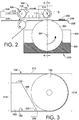
- FIG. 2 depicts an exemplary cross-sectional perspective of a system, such as the system 100 of FIG. 1 , in accordance with aspects hereof.
- the system of FIG. 2 is comprised of the vacuum enabled article transfer apparatus 102 and the adhesive applicator 200 discussed in FIG. 1 .
- Similarly numbered elements of FIG. 2 relate to the corresponding elements discussed with respect to FIG. 1 .
- the vacuum source 308 may be any vacuum source, such as an electrically driven, pneumatic driven, and/or hydraulic driven generator of vacuum pressure, a negative (reduced) pressure relative to atmospheric pressure.
- the connector 310 is illustrated for exemplary purposes and is not limiting in nature. It is contemplated that the connector may be of any size, shape, and/or position.
- the conveyance belt 104 and the engagement surface of the vacuum chamber 120 are in a contacting relationship, in the illustrated example.
- This contacting relationship allows for a seal-like bond to occur between the sliding conveyance belt 104 and the vacuum chamber 120 to ensure a sufficient amount of vacuum pressure is transferred through the belt 104 to the article 306 when being conveyed. If a gap existed between the conveyance belt 104 and the vacuum chamber 120, an insufficient amount of vacuum pressure may be transmitted through the conveyance belt 104 to effectively adhere the article 306 to the belt for conveyance, in an exemplary aspect.
- the adhesive containing vessel 202 is depicted containing a material 302, such as a hot-melt adhesive.
- the applicator roller 204 rotates through the material 302 such that a portion of the material 302 is transferred on the surface of the applicator roller 204 to an article, such as an article 306, as the article passes between the applicator roller 204 and the compression roller 112.
- a plane passing through the axis of rotation 114 and an axis of rotation 304 is aligned perpendicular to a plane defined by the conveyance belt 104 extending between the compression roller 112 and the second roller 116, in an exemplary aspect.
- Said plane extending between the axis of rotations for the compression roller 112 and the applicator roller 204 is also identified as cutline 4-4, which represents a cross sectional perspective for FIG. 4 hereinafter. Also, a highlighted region is depicted around the vacuum chamber 120 and the compression roller 112, which is magnified in FIG. 3 hereinafter.
- FIG. 3 depicts a focused cross-section of the vacuum chamber 120, the compression roller 112, and the conveyance belt 104, in accordance with aspects hereof. Similarly numbered elements of FIG. 3 relate to the corresponding elements discussed with respect to FIGS. 1 and 2 .
- FIG. 3 depicts the vacuum chamber 120 extending between the compression roller 112 and the conveyance belt 104 proximate a location where the conveyance belt 104 separates from contacting the compression roller 112.
- the vacuum chamber 120 extends between the compression roller 112 and the belt 104 a lateral distance represented by distance 316, which is measured from a vertical tangent 312 to the intersection of the engagement surface 122 and the first side 126.
- the distance 316 enhances the ability of the vacuum chamber 120 to acquire and adhere to the article following the application of a material (e.g., hot-melt adhesive).
- An acute angle 320 is formed between the engagement surface 122 and the first side 126. The acute angle allows for the vacuum chamber 120 to extend a greater distance 316 than a vacuum chamber having a similar height with a less acute angle, which aids in the acquisition of the article by the vacuum chamber 120, in an exemplary aspect.
- a diameter 318 of the compression roller 112 is greater than a height 314 of the vacuum chamber 120.
- This difference in height allows at least a portion of the vacuum chamber 120 to be positioned between a top portion and a bottom potion of the loop formed by the conveyance belt 104.
- This allows the vacuum chamber to remain stationary as the conveyance belt is operable to rotate (e.g., move) around the vacuum chamber. In this manner, potential complications with moving the vacuum source and/or vacuum chamber 120 may be avoided by instead moving the conveyance belt around the fixed vacuum chamber 120 to move an article.
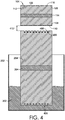
- FIG. 4 depicts a cross section along cut line 4-4 of FIG. 2 , in accordance with aspects hereof. Similarly numbered elements of FIG. 4 relate to the corresponding elements discussed with respect to FIGS. 1 and 2 .
- the conveyance belt 104 is depicted having the plurality of aperture 106 extending through both the contacting surface 110 and the inner surface 108. As such, it is contemplated that a vacuum pressures experienced proximate the inner surface 108 transfers through the belt 104 to an article near the contacting surface 110.
- the applicator roller 204 is depicted having a plurality of grooves 406 effective to receive and maintain the plurality of filaments 206.
- the grooves 406 allow for recces of the filaments 206 such that an outer surface 408 of the applicator roller 204 extends beyond the filaments 206 as recessed in the grooves 406.
- the extension of the outer surface 408 allows contact between the applicator roller 204 and the article to occur with limited interference from the filaments 206.
- an effective transfer of material e.g., hot-melt adhesive
- a compression height 410 is depicted as extending between the contacting surface 110 of the conveyance belt 104 and the outer surface 408 of the applicator roller 204.
- the compression height 410 may be adjusted by raising/lowering one or more of the elements provided herein.
- the compression height 410 is from 85% to 100% a thickness of the article to be passed there through. Stated differently, it is contemplated that the compression height 410 is within 15% the height of an article onto which a material is to be applied. This compression height 410 allows a desired amount of compression to be applied to the article to ensure an appropriate and sufficient application of material is achieved.
- FIG. 4 illustrates exemplary configurations of elements, it is understood that any configuration, size, shape, and relative position may be used.
- the grooves 406 are depicted as being uniform in nature, it is contemplated that a higher concentration of grooves may be positioned in a primary working zone, in an exemplary aspect.
- an exemplary size, shape, and position of the apertures 106 are depicted, it is contemplated that alternative may be implemented.
- a width of the compression roller 112 and the applicator roller 204 are depicted as being substantially similar, it is contemplated that different widths and sizes may be implemented.
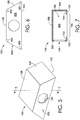
- FIG. 5 depicts an isomeric perspective of the vacuum chamber 120, in accordance with aspects hereof. Similarly numbered elements of FIG. 5 relate to the corresponding elements discussed with respect to FIG. 1 .
- the vacuum chamber 120 is comprised of the top surface 128, the first side 126, the engagement surface 122, the inlet 124, and a front face 502.
- the inlet 124 serves as a connection port for fluidly coupling an internal volume of the vacuum chamber 120 with a vacuum source. It is contemplated that additional inlets may be implemented to allow for the coupling or distribution of additional vacuum pressure.
- a cut line 7-7 that will represent the cross section of FIG. 7 hereinafter.
- FIG. 6 depicts the front face 502 of the vacuum chamber 120, in accordance with aspects hereof.
- FIG. 6 highlights a trapezoidal configuration of the front face 502 that is effective to extend the engagement surface 122 between the compression roller 112 and the conveyance belt of FIG. 2 .
- the trapezoidal shape of the front face 502 is also effective, in an exemplary aspect, to extend engagement surface 122 between the second roller 116 and the conveyance belt 104 of FIG. 2 .
- the first side 126 and a second side 608 are depicted as being linear in nature, it is contemplated that an arc or curve may be applied to better conform to the contours of the respective proximal rollers of each side.
- the formation of the trapezoidal front face 502 results in obtuse angles 602 and 604 as well as acute angles 606 and 320.
- the acute angles 320 and 606 ma allow for a greater inclusion of the engagement surface 122 between a roller and the conveyance belt to increase an area of the conveyance belt for which vacuum pressure is applied/transmitted.
- FIG. 7 depicts a cross section of the vacuum chamber 120 extending from the front face 502 to a back face 504, in accordance with aspects hereof.
- FIG. 7 depicts an internal volume 7006 that is substantially bounded by the top surface 128, the front face 502, the back face 504, the second side 608, the first side 126 (not depicted in the cut view), and the engagement surface 122.
- the engagement surface is expanded with an extension 702 from the front face 502 and an extension 704 from the back face 504.
- the extensions 702 and 704 may extend from the respective faces any length to result in an engagement surface aperture 708 through which vacuum pressure is transferred through a conveyance belt.
- the extensions 702 and/or 702 may be formed to concentrate that engagement surface aperture 708 over a serviceable portion of the conveyance belt, in an exemplary aspect. Further, it is contemplated that the extensions 702 and 704 may be omitted altogether, such as when the front face 502 and the back face 504 have a separation approximate that of a serviceable region of an underlying conveyance belt.
- FIG. 8 depicts a flow diagram 800 illustrating a method for transferring an article using at least a vacuum enabled article transfer apparatus, in accordance with aspects hereof.
- a step of compressing an article between a compression roller and an applicator roller is provided.
- an article such as a portion of material to use in the formation of an article of apparel or footwear may be fed between counter rotating compression roller and applicator roller having a compression height equal to or less than the thickness of the article.
- the counter rotation of the spaced apart rollers is effective to move the article between the rollers.
- a step of applying a material to a first side of the article is provided.
- the applicator roller of block 802 is a carrier of the material, such as a hot-melt.
- the compression of the article in block 802 aids in a transfer of material from the applicator roller to the article such that the material is applied to the surface of the article in contact with the applicator roller.
- a step of temporarily adhering, with vacuum pressure, the article to a belt is provided.
- vacuum pressure is applied within a vacuum chamber that is in fluid communication with a belt having apertures extending through the belt
- the vacuum pressure passes through the belt to the article to create a negative pressure attraction force effective for adhering the article to the belt.
- This adhesion is temporary in that the adhesion is effective only while the negative pressure is applied through the belt. Therefore, as the belt move out of a region supplying the vacuum pressure or as the vacuum pressure is removed, the adhesion of the article to the belt is also eliminated.
- a step of moving the belt from a first position to a second position while maintaining the vacuum adhesion between the belt and article is provided.
- a vacuum pressure zone such as one provided by a vacuum chamber
- the article moves from a first position to a second position. This movement may allow the entirety of the article to have material applied to the first side, as provided in block 804 while limiting contact of the first side with a supporting structure as the article moves.
- a step of moving the belt from the second position to a third position such that the vacuum adhesion adhering the article to the belt is insufficient to maintain the adhesion at the third position. For example, as the belt slides beyond a vacuum pressure region of a vacuum chamber, a vacuum pressure sufficient to adhere the article to the belt is no longer present. At the third position, the belt is no longer sufficient for conveying the article as the article is no longer adhered to the belt.
- a step of transferring the article to a secondary transportation mechanism is provided.
- the secondary transportation mechanism may be a conveyance belt that contacts the first side of the article.
- the vacuum enabled article transfer apparatus may have maintained the article for a time sufficient to limit the transfer of applied material from the article to the second transportation mechanism, in an exemplary aspect.
- FIG. 8 While specific reference in FIG. 8 is made to one or more steps, it is contemplated that one or more additional or alternative steps may be implemented while achieving aspects provided herein. As such, blocks may be added or omitted while still staying within the scope hereof.
Landscapes
- Engineering & Computer Science (AREA)
- Mechanical Engineering (AREA)
- Chemical & Material Sciences (AREA)
- Organic Chemistry (AREA)
- Adhesives Or Adhesive Processes (AREA)
- Belt Conveyors (AREA)
- Container, Conveyance, Adherence, Positioning, Of Wafer (AREA)
- Blow-Moulding Or Thermoforming Of Plastics Or The Like (AREA)
- Lining Or Joining Of Plastics Or The Like (AREA)
Claims (15)
- Appareil de transfert d'article par le vide (102), l'appareil (102) comprenant :- une courroie de transport (104) présentant une pluralité d'ouvertures (106) s'étendant à travers une surface de contact (110) vers une surface intérieure (108) opposée de la courroie de transport (104) ;- un rouleau de compression (112) ;- un deuxième rouleau (116), dans lequel la courroie de transport (104) forme une boucle continue autour du rouleau de compression (112) et du deuxième rouleau (116), de sorte que la surface intérieure de courroie (108) est en contact avec le rouleau de compression (112) et le deuxième rouleau (116) ; et- une chambre de distribution de vide (120), la chambre (120) étant positionnée entre le rouleau de compression (112) et le deuxième rouleau (116) à l'intérieur de la boucle de la courroie de transport (104), dans lequel la chambre (120) est composée d'une surface d'engagement (122) à proximité de la surface intérieure de courroie (108) et opérationnelle pour diriger une pression négative à travers la courroie (104) vers la pluralité d'ouvertures (106) ;caractérisé en ce que l'appareil comprend en outre :- un applicateur d'adhésif (200), l'applicateur (200) comprenant un rouleau d'applicateur (204) et un récipient contenant de l'adhésif (202), le rouleau d'applicateur (204) étant positionné de façon rotative au moins partiellement dans le récipient contenant de l'adhésif (202),dans lequel l'applicateur d'adhésif (200) comprend en outre une pluralité de filaments de transfert (206), les filaments de transfert (206) s'étendant entre le rouleau d'applicateur (204) et la courroie (104).
- Appareil de transfert d'article par le vide (102) selon la revendication 1, dans lequel le rouleau de compression (112) présente un diamètre (318) supérieur à une hauteur (314) de la chambre (120) à l'intérieur de la boucle formée par la courroie (104).
- Appareil de transfert d'article par le vide (102) selon la revendication 1, comprenant en outre un générateur de vide accouplé fluidiquement à la chambre (120).
- Appareil de transfert d'article par le vide (102) selon la revendication 1, dans lequel la surface d'engagement (122) de la chambre (120) s'étend entre une partie au moins du rouleau de compression (112) et la courroie (104).
- Appareil de transfert d'article par le vide (102) selon la revendication 1, dans lequel le rouleau d'applicateur (204) présente un diamètre supérieur à un diamètre (318) du rouleau de compression (112).
- Appareil de transfert d'article par le vide (102) selon la revendication 1, dans lequel un axe de rotation (114) du rouleau de compression (112) et un axe de rotation (304) du rouleau d'applicateur (204) sont substantiellement alignés dans un plan perpendiculaire à un plan à travers lequel s'étend la courroie (104) entre le rouleau de compression (112) et le deuxième rouleau (116).
- Appareil de transfert d'article par le vide (102) selon la revendication 1, dans lequel les filaments de transfert (206) sont accouplé thermiquement à une source d'énergie (208), de telle façon que les filaments de transfert (206) sont maintenus au-dessus d'une température seuil, et, facultativement,
dans lequel la température seuil est une température dans une plage de 75 à 240 degrés Celsius. - Appareil de transfert d'article par le vide (102) selon la revendication 1, dans lequel les filaments de transfert (206) s'étendent au moins partiellement dans un plan substantiellement parallèle à un plan dans lequel la courroie (104) s'étend entre le rouleau de compression (112) et le deuxième rouleau (116).
- Appareil de transfert d'article par le vide (102) selon la revendication 1, dans lequel la chambre de distribution de vide (120) présente un premier côté (126) s'étendant à partir de la surface d'engagement (122) selon un angle aigu (320) vers une surface supérieure, et, facultativement,
dans lequel une partie au moins du premier côté (126) s'étend le long du rouleau de compression (112) et entre le rouleau de compression (112) et la courroie (104). - Procédé de transfert d'article (306), le procédé comprenant :- la réception de l'article (306) à une position sur un appareil de transfert d'article par le vide (102) ;- l'application d'un matériau (302) sur un premier côté de l'article (306) ;- l'adhérence temporaire, avec une pression négative, de l'article (306) à une courroie de transport (104), la courroie (104) étant en contact avec un deuxième côté de l'article (306), le deuxième côté étant opposé au premier côté ;- tout en maintenant l'adhérence sous vide de l'article (306) à la courroie (104) ; le déplacement de la courroie (104) d'une première position vers une deuxième position ;- le déplacement de la courroie (104) de la deuxième position vers une troisième position, de telle façon qu'à la troisième position, l'adhérence sous vide est insuffisante pour contrebalancer une force de gravité sur l'article (306), de telle façon que l'article (306) n'adhère plus à la courroie (104) par adhérence sous vide,dans lequel un rouleau d'applicateur (204) applique le matériau (302) sur le premier côté de l'article (306), et dans lequel le matériau (302) est un adhésif,dans lequel l'appareil de transfert d'article par le vide (102) comprend un rouleau d'applicateur (204) et un récipient contenant de l'adhésif (202), le rouleau d'applicateur (204) étant positionné de façon rotative au moins partiellement dans le récipient contenant de l'adhésif (202),dans lequel l'applicateur d'adhésif (200) comprend en outre une pluralité de filaments de transfert (206), les filaments de transfert (206) s'étendant entre le rouleau d'applicateur (204) et la courroie (104).
- Procédé selon la revendication 10, dans lequel l'article (306) fait partie d'un article chaussant.
- Procédé selon la revendication 10, dans lequel la courroie (104) est composée d'une pluralité d'ouvertures (106) s'étendant à travers celle-ci pour permettre un transfert de pression négative à travers la courroie (104) vers l'article (306).
- Procédé selon la revendication 10, comprenant en outre la compression de l'article (306) entre un rouleau de compression (112) et le rouleau d'applicateur (204), le rouleau de compression (112) se trouvant dans une boucle formée par la courroie (104).
- Procédé selon la revendication 10, dans lequel la troisième position de la courroie (104) est un emplacement au-delà de la chambre à vide (120) appliquant la pression négative.
- Procédé selon la revendication 10, comprenant en outre le transfert de l'article (306) à partir de la courroie (104) vers un mécanisme de transport secondaire, le mécanisme de transport secondaire étant en contact avec le premier côté de l'article (306).
Applications Claiming Priority (3)
| Application Number | Priority Date | Filing Date | Title |
|---|---|---|---|
| US201462031383P | 2014-07-31 | 2014-07-31 | |
| US14/463,115 US9850404B2 (en) | 2014-07-31 | 2014-08-19 | Vacuum enabled article transfer |
| PCT/US2015/031025 WO2016018495A1 (fr) | 2014-07-31 | 2015-05-15 | Transfert d'article par le vide |
Publications (2)
| Publication Number | Publication Date |
|---|---|
| EP3140045A1 EP3140045A1 (fr) | 2017-03-15 |
| EP3140045B1 true EP3140045B1 (fr) | 2021-11-03 |
Family
ID=55179275
Family Applications (1)
| Application Number | Title | Priority Date | Filing Date |
|---|---|---|---|
| EP15727157.8A Active EP3140045B1 (fr) | 2014-07-31 | 2015-05-15 | Transfert d'article par le vide |
Country Status (7)
| Country | Link |
|---|---|
| US (2) | US9850404B2 (fr) |
| EP (1) | EP3140045B1 (fr) |
| KR (1) | KR102010675B1 (fr) |
| CN (1) | CN105314417B (fr) |
| MX (1) | MX2017001455A (fr) |
| TW (1) | TWI603787B (fr) |
| WO (1) | WO2016018495A1 (fr) |
Families Citing this family (20)
| Publication number | Priority date | Publication date | Assignee | Title |
|---|---|---|---|---|
| US9968493B2 (en) * | 2015-12-01 | 2018-05-15 | The Procter & Gamble Company | Methods and apparatuses for moving and/or transferring multiple discrete articles |
| WO2018111292A1 (fr) * | 2016-12-16 | 2018-06-21 | Kimberly-Clark Worldwide, Inc. | Rouleau de nez sous vide |
| US11055504B2 (en) | 2017-04-18 | 2021-07-06 | Berkshire Grey, Inc. | Systems and methods for separating objects using a vacuum roller with one or more object processing systems |
| US11373134B2 (en) | 2018-10-23 | 2022-06-28 | Berkshire Grey Operating Company, Inc. | Systems and methods for dynamic processing of objects with data verification |
| US11301654B2 (en) | 2017-04-18 | 2022-04-12 | Berkshire Grey Operating Company, Inc. | Systems and methods for limiting induction of objects to one or more object processing systems |
| US11080496B2 (en) | 2017-04-18 | 2021-08-03 | Berkshire Grey, Inc. | Systems and methods for separating objects using vacuum diverts with one or more object processing systems |
| US11416695B2 (en) | 2017-04-18 | 2022-08-16 | Berkshire Grey Operating Company, Inc. | Systems and methods for distributing induction of objects to a plurality of object processing systems |
| EP3612472A1 (fr) | 2017-04-18 | 2020-02-26 | Berkshire Grey, Inc. | Systèmes et procédés de traitement d'objets comprenant des stations de distribution efficaces dans l'espace et un traitement de sortie automatisé |
| US11200390B2 (en) | 2017-04-18 | 2021-12-14 | Berkshire Grey, Inc. | Systems and methods for separating objects using drop conveyors with one or more object processing systems |
| US11205059B2 (en) | 2017-04-18 | 2021-12-21 | Berkshire Grey, Inc. | Systems and methods for separating objects using conveyor transfer with one or more object processing systems |
| CN106923447A (zh) * | 2017-05-09 | 2017-07-07 | 安徽省石台东生鞋业有限公司 | 一种鞋厂用鞋底上胶装置 |
| CN107140365B (zh) * | 2017-05-25 | 2023-04-28 | 苏州誉阵自动化科技有限公司 | 一种真空吸附传送装置以及瓶盖检测装置 |
| JP2020045192A (ja) * | 2018-09-18 | 2020-03-26 | セイコーエプソン株式会社 | 媒体搬送装置、媒体処理装置、及び記録システム |
| EP3908991A1 (fr) * | 2019-01-08 | 2021-11-17 | Berkshire Grey, Inc. | Systèmes et procédés de séparer d'objets à l'aide d'un rouleau vide avec un ou plusieurs systèmes de traitement d'objets |
| AU2020261812B2 (en) | 2019-04-15 | 2022-12-22 | Daikin Industries, Ltd. | Air supply system |
| WO2020213216A1 (fr) | 2019-04-15 | 2020-10-22 | ダイキン工業株式会社 | Système de conditionnement d'air |
| US11384419B2 (en) * | 2019-08-30 | 2022-07-12 | Micromaierials Llc | Apparatus and methods for depositing molten metal onto a foil substrate |
| CN111974788B (zh) * | 2020-09-07 | 2023-12-05 | 青海黄河上游水电开发有限责任公司光伏产业技术分公司 | 一种剥离机构及剥离方法 |
| CN118984802A (zh) | 2022-03-23 | 2024-11-19 | 伯克希尔格雷营业股份有限公司 | 用于动态处理物体的缓冲系统和方法 |
| CN115402793A (zh) * | 2022-08-22 | 2022-11-29 | 潍坊兴明光电科技有限公司 | 玻璃传送装置和玻璃传送系统 |
Citations (1)
| Publication number | Priority date | Publication date | Assignee | Title |
|---|---|---|---|---|
| DE2939102A1 (de) * | 1979-09-27 | 1981-04-16 | Henkel KGaA, 4000 Düsseldorf | Klebstoffauftragsvorrichtung und verfahren zum betrieb derselben |
Family Cites Families (21)
| Publication number | Priority date | Publication date | Assignee | Title |
|---|---|---|---|---|
| US3353517A (en) * | 1965-01-14 | 1967-11-21 | M B Claff & Sons Inc | Apparatus for applying a film of glue to box blanks and the like |
| US3372826A (en) * | 1966-03-30 | 1968-03-12 | Owens Illinois Inc | Composite container |
| US3477558A (en) * | 1966-10-27 | 1969-11-11 | Fred J Fleischauer | Air lift and vacuum conveyors and foraminous belt means therefor |
| US3637074A (en) * | 1970-03-31 | 1972-01-25 | Owens Illinois Inc | Container handling apparatus |
| US3659840A (en) * | 1970-06-15 | 1972-05-02 | Connecticut Bank And Trust Co | Vacuum gate |
| US4141462A (en) * | 1977-11-07 | 1979-02-27 | Rucci Charles D | Device for decreasing heat transfer and slosh from a beverage container |
| DE2922978C2 (de) * | 1979-06-06 | 1983-07-07 | Planatolwerk Willy Hesselmann, Chemische und Maschinenfabrik für Klebetechnik, 8201 Thansau | Vorrichtung und Verfahren zum Auftragen von Klebstoff, insbesondere zum Beleimen von Blattstapeln |
| US4290837A (en) * | 1979-12-28 | 1981-09-22 | Bova Joseph D | Method and apparatus for making unexpanded honeycomb material |
| US4286870A (en) | 1980-01-10 | 1981-09-01 | Xerox Corporation | Document belt with discrete vacuum areas |
| US4291974A (en) * | 1980-01-10 | 1981-09-29 | Xerox Corporation | Dual mode document belt system |
| US4456242A (en) * | 1981-05-11 | 1984-06-26 | Morin George A | Apparatus for shingling stack of flat articles |
| US4771879A (en) * | 1987-07-01 | 1988-09-20 | Adolph Coors Company | Container transfer system |
| US5534063A (en) | 1993-07-21 | 1996-07-09 | Ricoh Company, Ltd. | Apparatus for removing image forming substance from sheet and sheet processing apparatus |
| US5564693A (en) * | 1995-02-01 | 1996-10-15 | Ward Holding Company, Inc. | Paperboard processing machine with vacuum transfer system |
| US5548388A (en) | 1995-09-25 | 1996-08-20 | Xerox Corporation | Vacuum transport apparatus |
| JP3498122B2 (ja) * | 1999-10-26 | 2004-02-16 | 株式会社ヒラノテクシード | 単板の塗工装置 |
| WO2001072617A1 (fr) * | 2000-03-31 | 2001-10-04 | Jaime Marti Sala | Machine lineaire automatique permettant d'orienter et d'aligner des articles |
| JP2001305561A (ja) * | 2000-04-21 | 2001-10-31 | Hitachi Ltd | 液晶表示装置 |
| EP1155983A1 (fr) * | 2000-05-16 | 2001-11-21 | Albin Spitzke KG (GmbH & Co.) | Dispositif d' empilement de plaques |
| US20080271344A1 (en) * | 2005-02-18 | 2008-11-06 | Simon Jeremy Skirrow | Goat Skin for Shoe and Apparel Manufacture |
| CN204727252U (zh) | 2014-07-31 | 2015-10-28 | 耐克创新有限合伙公司 | 真空致能型物品转移装置 |
-
2014
- 2014-08-19 US US14/463,115 patent/US9850404B2/en active Active
-
2015
- 2015-03-31 CN CN201510147719.2A patent/CN105314417B/zh active Active
- 2015-05-15 WO PCT/US2015/031025 patent/WO2016018495A1/fr not_active Ceased
- 2015-05-15 EP EP15727157.8A patent/EP3140045B1/fr active Active
- 2015-05-15 KR KR1020177004496A patent/KR102010675B1/ko active Active
- 2015-05-15 MX MX2017001455A patent/MX2017001455A/es unknown
- 2015-06-11 TW TW104118851A patent/TWI603787B/zh active
-
2017
- 2017-12-07 US US15/835,335 patent/US10844245B2/en active Active
Patent Citations (1)
| Publication number | Priority date | Publication date | Assignee | Title |
|---|---|---|---|---|
| DE2939102A1 (de) * | 1979-09-27 | 1981-04-16 | Henkel KGaA, 4000 Düsseldorf | Klebstoffauftragsvorrichtung und verfahren zum betrieb derselben |
Also Published As
| Publication number | Publication date |
|---|---|
| US20160031651A1 (en) | 2016-02-04 |
| KR20170036720A (ko) | 2017-04-03 |
| US10844245B2 (en) | 2020-11-24 |
| CN105314417A (zh) | 2016-02-10 |
| US9850404B2 (en) | 2017-12-26 |
| TWI603787B (zh) | 2017-11-01 |
| EP3140045A1 (fr) | 2017-03-15 |
| US20180100087A1 (en) | 2018-04-12 |
| WO2016018495A1 (fr) | 2016-02-04 |
| MX2017001455A (es) | 2017-05-09 |
| KR102010675B1 (ko) | 2019-08-13 |
| CN105314417B (zh) | 2018-09-28 |
| TW201603898A (zh) | 2016-02-01 |
Similar Documents
| Publication | Publication Date | Title |
|---|---|---|
| EP3140045B1 (fr) | Transfert d'article par le vide | |
| US12060176B2 (en) | Systems and processes for packing articles of footwear | |
| EP3041772B1 (fr) | Plaque pour un contre-cylindre avec une zone de vide réduit pour une utilisation dans un système de glissement-découpe et procédé d'utilisation correspondant | |
| US9248057B2 (en) | Method of applying bulk glue for nursing pad base film to four corners of sanitary product nursing pad base film and device therefor | |
| CN108602639B (zh) | 用于将凸片布施到底盘幅材的单元 | |
| TW201836959A (zh) | 玻璃薄膜之製造方法 | |
| KR101622151B1 (ko) | 판재용 포장기계장치 | |
| JP6621365B2 (ja) | 保護テープの剥離方法 | |
| KR20170027289A (ko) | 보호 테이프 부착 방법 및 보호 테이프 부착 장치 | |
| TWI556978B (zh) | 熱轉印裝置及熱轉印方法 | |
| KR20170021202A (ko) | 보호 테이프 부착 방법 | |
| JP6500170B2 (ja) | 基板への接着テープ貼り付け装置及び貼り付け方法 | |
| EP1561387A3 (fr) | Dispositif de laminage | |
| WO2011053153A1 (fr) | Dispositif de manipulation de galettes | |
| WO2016108350A1 (fr) | Appareil pour fabriquer en continu un récipient d'emballage réalisé en carton ondulé | |
| JP2022107888A (ja) | テープ供給装置およびテープ供給方法 | |
| KR200485246Y1 (ko) | 기판 필름 접착용 습식 자동 커팅 라미네이팅 장치 | |
| CN107107520B (zh) | 用于冷却施加到袋体表面的粘合剂的装置 | |
| KR101590088B1 (ko) | 패드 박리 장치 및 이를 포함하는 유리판 연마 시스템 | |
| KR20170021984A (ko) | 기판 필름 접착용 습식 자동 커팅 라미네이팅 장치 | |
| CN206590638U (zh) | 卷材包装用内周保护板的连接装置 | |
| CN121605503A (zh) | 二次电池用电极片防斜行型干燥室装置 | |
| JP2005185867A (ja) | 遊技機製造用化粧シート貼付装置 | |
| KR20190112510A (ko) | 포장용 박스 제조장치 |
Legal Events
| Date | Code | Title | Description |
|---|---|---|---|
| STAA | Information on the status of an ep patent application or granted ep patent |
Free format text: STATUS: THE INTERNATIONAL PUBLICATION HAS BEEN MADE |
|
| PUAI | Public reference made under article 153(3) epc to a published international application that has entered the european phase |
Free format text: ORIGINAL CODE: 0009012 |
|
| STAA | Information on the status of an ep patent application or granted ep patent |
Free format text: STATUS: REQUEST FOR EXAMINATION WAS MADE |
|
| 17P | Request for examination filed |
Effective date: 20161128 |
|
| AK | Designated contracting states |
Kind code of ref document: A1 Designated state(s): AL AT BE BG CH CY CZ DE DK EE ES FI FR GB GR HR HU IE IS IT LI LT LU LV MC MK MT NL NO PL PT RO RS SE SI SK SM TR |
|
| AX | Request for extension of the european patent |
Extension state: BA ME |
|
| RIN1 | Information on inventor provided before grant (corrected) |
Inventor name: HSIEH, CHIA-HUNG, C/O POU CHEN CORPORATION Inventor name: HUANG, CHUN-TA, C/O POU CHEN CORPORATION Inventor name: LIN, CHIUNG-LUNG, C/O POU CHEN CORPORATION |
|
| DAV | Request for validation of the european patent (deleted) | ||
| DAX | Request for extension of the european patent (deleted) | ||
| RIN1 | Information on inventor provided before grant (corrected) |
Inventor name: HSIEH, CHIA-HUNG, C/O POU CHEN CORPORATION Inventor name: HUANG, CHUN-TA, C/O POU CHEN CORPORATION Inventor name: LIN, CHIUNG-LUNG, C/O POU CHEN CORPORATION |
|
| STAA | Information on the status of an ep patent application or granted ep patent |
Free format text: STATUS: EXAMINATION IS IN PROGRESS |
|
| 17Q | First examination report despatched |
Effective date: 20190528 |
|
| GRAP | Despatch of communication of intention to grant a patent |
Free format text: ORIGINAL CODE: EPIDOSNIGR1 |
|
| STAA | Information on the status of an ep patent application or granted ep patent |
Free format text: STATUS: GRANT OF PATENT IS INTENDED |
|
| INTG | Intention to grant announced |
Effective date: 20210602 |
|
| GRAS | Grant fee paid |
Free format text: ORIGINAL CODE: EPIDOSNIGR3 |
|
| GRAA | (expected) grant |
Free format text: ORIGINAL CODE: 0009210 |
|
| STAA | Information on the status of an ep patent application or granted ep patent |
Free format text: STATUS: THE PATENT HAS BEEN GRANTED |
|
| AK | Designated contracting states |
Kind code of ref document: B1 Designated state(s): AL AT BE BG CH CY CZ DE DK EE ES FI FR GB GR HR HU IE IS IT LI LT LU LV MC MK MT NL NO PL PT RO RS SE SI SK SM TR |
|
| REG | Reference to a national code |
Ref country code: GB Ref legal event code: FG4D |
|
| REG | Reference to a national code |
Ref country code: AT Ref legal event code: REF Ref document number: 1443492 Country of ref document: AT Kind code of ref document: T Effective date: 20211115 Ref country code: CH Ref legal event code: EP |
|
| REG | Reference to a national code |
Ref country code: IE Ref legal event code: FG4D |
|
| REG | Reference to a national code |
Ref country code: DE Ref legal event code: R096 Ref document number: 602015074655 Country of ref document: DE |
|
| REG | Reference to a national code |
Ref country code: LT Ref legal event code: MG9D |
|
| REG | Reference to a national code |
Ref country code: NL Ref legal event code: MP Effective date: 20211103 |
|
| REG | Reference to a national code |
Ref country code: AT Ref legal event code: MK05 Ref document number: 1443492 Country of ref document: AT Kind code of ref document: T Effective date: 20211103 |
|
| PG25 | Lapsed in a contracting state [announced via postgrant information from national office to epo] |
Ref country code: RS Free format text: LAPSE BECAUSE OF FAILURE TO SUBMIT A TRANSLATION OF THE DESCRIPTION OR TO PAY THE FEE WITHIN THE PRESCRIBED TIME-LIMIT Effective date: 20211103 Ref country code: LT Free format text: LAPSE BECAUSE OF FAILURE TO SUBMIT A TRANSLATION OF THE DESCRIPTION OR TO PAY THE FEE WITHIN THE PRESCRIBED TIME-LIMIT Effective date: 20211103 Ref country code: FI Free format text: LAPSE BECAUSE OF FAILURE TO SUBMIT A TRANSLATION OF THE DESCRIPTION OR TO PAY THE FEE WITHIN THE PRESCRIBED TIME-LIMIT Effective date: 20211103 Ref country code: BG Free format text: LAPSE BECAUSE OF FAILURE TO SUBMIT A TRANSLATION OF THE DESCRIPTION OR TO PAY THE FEE WITHIN THE PRESCRIBED TIME-LIMIT Effective date: 20220203 Ref country code: AT Free format text: LAPSE BECAUSE OF FAILURE TO SUBMIT A TRANSLATION OF THE DESCRIPTION OR TO PAY THE FEE WITHIN THE PRESCRIBED TIME-LIMIT Effective date: 20211103 |
|
| PG25 | Lapsed in a contracting state [announced via postgrant information from national office to epo] |
Ref country code: IS Free format text: LAPSE BECAUSE OF FAILURE TO SUBMIT A TRANSLATION OF THE DESCRIPTION OR TO PAY THE FEE WITHIN THE PRESCRIBED TIME-LIMIT Effective date: 20220303 Ref country code: SE Free format text: LAPSE BECAUSE OF FAILURE TO SUBMIT A TRANSLATION OF THE DESCRIPTION OR TO PAY THE FEE WITHIN THE PRESCRIBED TIME-LIMIT Effective date: 20211103 Ref country code: PT Free format text: LAPSE BECAUSE OF FAILURE TO SUBMIT A TRANSLATION OF THE DESCRIPTION OR TO PAY THE FEE WITHIN THE PRESCRIBED TIME-LIMIT Effective date: 20220303 Ref country code: PL Free format text: LAPSE BECAUSE OF FAILURE TO SUBMIT A TRANSLATION OF THE DESCRIPTION OR TO PAY THE FEE WITHIN THE PRESCRIBED TIME-LIMIT Effective date: 20211103 Ref country code: NO Free format text: LAPSE BECAUSE OF FAILURE TO SUBMIT A TRANSLATION OF THE DESCRIPTION OR TO PAY THE FEE WITHIN THE PRESCRIBED TIME-LIMIT Effective date: 20220203 Ref country code: NL Free format text: LAPSE BECAUSE OF FAILURE TO SUBMIT A TRANSLATION OF THE DESCRIPTION OR TO PAY THE FEE WITHIN THE PRESCRIBED TIME-LIMIT Effective date: 20211103 Ref country code: LV Free format text: LAPSE BECAUSE OF FAILURE TO SUBMIT A TRANSLATION OF THE DESCRIPTION OR TO PAY THE FEE WITHIN THE PRESCRIBED TIME-LIMIT Effective date: 20211103 Ref country code: HR Free format text: LAPSE BECAUSE OF FAILURE TO SUBMIT A TRANSLATION OF THE DESCRIPTION OR TO PAY THE FEE WITHIN THE PRESCRIBED TIME-LIMIT Effective date: 20211103 Ref country code: GR Free format text: LAPSE BECAUSE OF FAILURE TO SUBMIT A TRANSLATION OF THE DESCRIPTION OR TO PAY THE FEE WITHIN THE PRESCRIBED TIME-LIMIT Effective date: 20220204 Ref country code: ES Free format text: LAPSE BECAUSE OF FAILURE TO SUBMIT A TRANSLATION OF THE DESCRIPTION OR TO PAY THE FEE WITHIN THE PRESCRIBED TIME-LIMIT Effective date: 20211103 |
|
| PG25 | Lapsed in a contracting state [announced via postgrant information from national office to epo] |
Ref country code: SM Free format text: LAPSE BECAUSE OF FAILURE TO SUBMIT A TRANSLATION OF THE DESCRIPTION OR TO PAY THE FEE WITHIN THE PRESCRIBED TIME-LIMIT Effective date: 20211103 Ref country code: SK Free format text: LAPSE BECAUSE OF FAILURE TO SUBMIT A TRANSLATION OF THE DESCRIPTION OR TO PAY THE FEE WITHIN THE PRESCRIBED TIME-LIMIT Effective date: 20211103 Ref country code: RO Free format text: LAPSE BECAUSE OF FAILURE TO SUBMIT A TRANSLATION OF THE DESCRIPTION OR TO PAY THE FEE WITHIN THE PRESCRIBED TIME-LIMIT Effective date: 20211103 Ref country code: EE Free format text: LAPSE BECAUSE OF FAILURE TO SUBMIT A TRANSLATION OF THE DESCRIPTION OR TO PAY THE FEE WITHIN THE PRESCRIBED TIME-LIMIT Effective date: 20211103 Ref country code: DK Free format text: LAPSE BECAUSE OF FAILURE TO SUBMIT A TRANSLATION OF THE DESCRIPTION OR TO PAY THE FEE WITHIN THE PRESCRIBED TIME-LIMIT Effective date: 20211103 Ref country code: CZ Free format text: LAPSE BECAUSE OF FAILURE TO SUBMIT A TRANSLATION OF THE DESCRIPTION OR TO PAY THE FEE WITHIN THE PRESCRIBED TIME-LIMIT Effective date: 20211103 |
|
| REG | Reference to a national code |
Ref country code: DE Ref legal event code: R097 Ref document number: 602015074655 Country of ref document: DE |
|
| PLBE | No opposition filed within time limit |
Free format text: ORIGINAL CODE: 0009261 |
|
| STAA | Information on the status of an ep patent application or granted ep patent |
Free format text: STATUS: NO OPPOSITION FILED WITHIN TIME LIMIT |
|
| 26N | No opposition filed |
Effective date: 20220804 |
|
| PG25 | Lapsed in a contracting state [announced via postgrant information from national office to epo] |
Ref country code: AL Free format text: LAPSE BECAUSE OF FAILURE TO SUBMIT A TRANSLATION OF THE DESCRIPTION OR TO PAY THE FEE WITHIN THE PRESCRIBED TIME-LIMIT Effective date: 20211103 |
|
| PG25 | Lapsed in a contracting state [announced via postgrant information from national office to epo] |
Ref country code: SI Free format text: LAPSE BECAUSE OF FAILURE TO SUBMIT A TRANSLATION OF THE DESCRIPTION OR TO PAY THE FEE WITHIN THE PRESCRIBED TIME-LIMIT Effective date: 20211103 |
|
| REG | Reference to a national code |
Ref country code: CH Ref legal event code: PL |
|
| REG | Reference to a national code |
Ref country code: BE Ref legal event code: MM Effective date: 20220531 |
|
| PG25 | Lapsed in a contracting state [announced via postgrant information from national office to epo] |
Ref country code: MC Free format text: LAPSE BECAUSE OF FAILURE TO SUBMIT A TRANSLATION OF THE DESCRIPTION OR TO PAY THE FEE WITHIN THE PRESCRIBED TIME-LIMIT Effective date: 20211103 Ref country code: LU Free format text: LAPSE BECAUSE OF NON-PAYMENT OF DUE FEES Effective date: 20220515 Ref country code: LI Free format text: LAPSE BECAUSE OF NON-PAYMENT OF DUE FEES Effective date: 20220531 Ref country code: CH Free format text: LAPSE BECAUSE OF NON-PAYMENT OF DUE FEES Effective date: 20220531 |
|
| PG25 | Lapsed in a contracting state [announced via postgrant information from national office to epo] |
Ref country code: IE Free format text: LAPSE BECAUSE OF NON-PAYMENT OF DUE FEES Effective date: 20220515 |
|
| PG25 | Lapsed in a contracting state [announced via postgrant information from national office to epo] |
Ref country code: IT Free format text: LAPSE BECAUSE OF FAILURE TO SUBMIT A TRANSLATION OF THE DESCRIPTION OR TO PAY THE FEE WITHIN THE PRESCRIBED TIME-LIMIT Effective date: 20211103 Ref country code: BE Free format text: LAPSE BECAUSE OF NON-PAYMENT OF DUE FEES Effective date: 20220531 |
|
| P01 | Opt-out of the competence of the unified patent court (upc) registered |
Effective date: 20230515 |
|
| PG25 | Lapsed in a contracting state [announced via postgrant information from national office to epo] |
Ref country code: HU Free format text: LAPSE BECAUSE OF FAILURE TO SUBMIT A TRANSLATION OF THE DESCRIPTION OR TO PAY THE FEE WITHIN THE PRESCRIBED TIME-LIMIT; INVALID AB INITIO Effective date: 20150515 |
|
| PG25 | Lapsed in a contracting state [announced via postgrant information from national office to epo] |
Ref country code: MK Free format text: LAPSE BECAUSE OF FAILURE TO SUBMIT A TRANSLATION OF THE DESCRIPTION OR TO PAY THE FEE WITHIN THE PRESCRIBED TIME-LIMIT Effective date: 20211103 Ref country code: CY Free format text: LAPSE BECAUSE OF FAILURE TO SUBMIT A TRANSLATION OF THE DESCRIPTION OR TO PAY THE FEE WITHIN THE PRESCRIBED TIME-LIMIT Effective date: 20211103 |
|
| PG25 | Lapsed in a contracting state [announced via postgrant information from national office to epo] |
Ref country code: TR Free format text: LAPSE BECAUSE OF FAILURE TO SUBMIT A TRANSLATION OF THE DESCRIPTION OR TO PAY THE FEE WITHIN THE PRESCRIBED TIME-LIMIT Effective date: 20211103 |
|
| PG25 | Lapsed in a contracting state [announced via postgrant information from national office to epo] |
Ref country code: MT Free format text: LAPSE BECAUSE OF FAILURE TO SUBMIT A TRANSLATION OF THE DESCRIPTION OR TO PAY THE FEE WITHIN THE PRESCRIBED TIME-LIMIT Effective date: 20211103 |
|
| PGFP | Annual fee paid to national office [announced via postgrant information from national office to epo] |
Ref country code: DE Payment date: 20250319 Year of fee payment: 11 |
|
| PGFP | Annual fee paid to national office [announced via postgrant information from national office to epo] |
Ref country code: GB Payment date: 20260316 Year of fee payment: 12 |
|
| PGFP | Annual fee paid to national office [announced via postgrant information from national office to epo] |
Ref country code: FR Payment date: 20260309 Year of fee payment: 12 |