EP3140069B1 - Procédé et dispositif pour l'assemblage d'un élément structural en tôle composite avec un autre élément structural - Google Patents
Procédé et dispositif pour l'assemblage d'un élément structural en tôle composite avec un autre élément structural Download PDFInfo
- Publication number
- EP3140069B1 EP3140069B1 EP15719652.8A EP15719652A EP3140069B1 EP 3140069 B1 EP3140069 B1 EP 3140069B1 EP 15719652 A EP15719652 A EP 15719652A EP 3140069 B1 EP3140069 B1 EP 3140069B1
- Authority
- EP
- European Patent Office
- Prior art keywords
- component
- joint
- region
- intermediate layer
- components
- Prior art date
- Legal status (The legal status is an assumption and is not a legal conclusion. Google has not performed a legal analysis and makes no representation as to the accuracy of the status listed.)
- Active
Links
Images


Classifications
-
- B—PERFORMING OPERATIONS; TRANSPORTING
- B23—MACHINE TOOLS; METAL-WORKING NOT OTHERWISE PROVIDED FOR
- B23K—SOLDERING OR UNSOLDERING; WELDING; CLADDING OR PLATING BY SOLDERING OR WELDING; CUTTING BY APPLYING HEAT LOCALLY, e.g. FLAME CUTTING; WORKING BY LASER BEAM
- B23K11/00—Resistance welding; Severing by resistance heating
- B23K11/34—Preliminary treatment
-
- B—PERFORMING OPERATIONS; TRANSPORTING
- B23—MACHINE TOOLS; METAL-WORKING NOT OTHERWISE PROVIDED FOR
- B23K—SOLDERING OR UNSOLDERING; WELDING; CLADDING OR PLATING BY SOLDERING OR WELDING; CUTTING BY APPLYING HEAT LOCALLY, e.g. FLAME CUTTING; WORKING BY LASER BEAM
- B23K11/00—Resistance welding; Severing by resistance heating
- B23K11/002—Resistance welding; Severing by resistance heating specially adapted for particular articles or work
- B23K11/004—Welding of a small piece to a large or broad piece
- B23K11/0046—Welding of a small piece to a large or broad piece the extremity of a small piece being welded to a base, e.g. cooling studs or fins to tubes or plates
- B23K11/0053—Stud welding, i.e. resistive
-
- B—PERFORMING OPERATIONS; TRANSPORTING
- B23—MACHINE TOOLS; METAL-WORKING NOT OTHERWISE PROVIDED FOR
- B23K—SOLDERING OR UNSOLDERING; WELDING; CLADDING OR PLATING BY SOLDERING OR WELDING; CUTTING BY APPLYING HEAT LOCALLY, e.g. FLAME CUTTING; WORKING BY LASER BEAM
- B23K11/00—Resistance welding; Severing by resistance heating
- B23K11/06—Resistance welding; Severing by resistance heating using roller electrodes
-
- B—PERFORMING OPERATIONS; TRANSPORTING
- B23—MACHINE TOOLS; METAL-WORKING NOT OTHERWISE PROVIDED FOR
- B23K—SOLDERING OR UNSOLDERING; WELDING; CLADDING OR PLATING BY SOLDERING OR WELDING; CUTTING BY APPLYING HEAT LOCALLY, e.g. FLAME CUTTING; WORKING BY LASER BEAM
- B23K11/00—Resistance welding; Severing by resistance heating
- B23K11/10—Spot welding; Stitch welding
- B23K11/11—Spot welding
- B23K11/115—Spot welding by means of two electrodes placed opposite one another on both sides of the welded parts
-
- B—PERFORMING OPERATIONS; TRANSPORTING
- B23—MACHINE TOOLS; METAL-WORKING NOT OTHERWISE PROVIDED FOR
- B23K—SOLDERING OR UNSOLDERING; WELDING; CLADDING OR PLATING BY SOLDERING OR WELDING; CUTTING BY APPLYING HEAT LOCALLY, e.g. FLAME CUTTING; WORKING BY LASER BEAM
- B23K11/00—Resistance welding; Severing by resistance heating
- B23K11/16—Resistance welding; Severing by resistance heating taking account of the properties of the material to be welded
- B23K11/163—Welding of coated materials
-
- B—PERFORMING OPERATIONS; TRANSPORTING
- B23—MACHINE TOOLS; METAL-WORKING NOT OTHERWISE PROVIDED FOR
- B23K—SOLDERING OR UNSOLDERING; WELDING; CLADDING OR PLATING BY SOLDERING OR WELDING; CUTTING BY APPLYING HEAT LOCALLY, e.g. FLAME CUTTING; WORKING BY LASER BEAM
- B23K11/00—Resistance welding; Severing by resistance heating
- B23K11/24—Electric supply or control circuits therefor
- B23K11/25—Monitoring devices
- B23K11/252—Monitoring devices using digital means
- B23K11/253—Monitoring devices using digital means the measured parameter being a displacement or a position
-
- B—PERFORMING OPERATIONS; TRANSPORTING
- B23—MACHINE TOOLS; METAL-WORKING NOT OTHERWISE PROVIDED FOR
- B23K—SOLDERING OR UNSOLDERING; WELDING; CLADDING OR PLATING BY SOLDERING OR WELDING; CUTTING BY APPLYING HEAT LOCALLY, e.g. FLAME CUTTING; WORKING BY LASER BEAM
- B23K11/00—Resistance welding; Severing by resistance heating
- B23K11/24—Electric supply or control circuits therefor
- B23K11/25—Monitoring devices
- B23K11/252—Monitoring devices using digital means
- B23K11/258—Monitoring devices using digital means the measured parameter being a voltage
-
- B—PERFORMING OPERATIONS; TRANSPORTING
- B23—MACHINE TOOLS; METAL-WORKING NOT OTHERWISE PROVIDED FOR
- B23K—SOLDERING OR UNSOLDERING; WELDING; CLADDING OR PLATING BY SOLDERING OR WELDING; CUTTING BY APPLYING HEAT LOCALLY, e.g. FLAME CUTTING; WORKING BY LASER BEAM
- B23K11/00—Resistance welding; Severing by resistance heating
- B23K11/30—Features relating to electrodes
- B23K11/3009—Pressure electrodes
- B23K11/3018—Cooled pressure electrodes
-
- B—PERFORMING OPERATIONS; TRANSPORTING
- B23—MACHINE TOOLS; METAL-WORKING NOT OTHERWISE PROVIDED FOR
- B23K—SOLDERING OR UNSOLDERING; WELDING; CLADDING OR PLATING BY SOLDERING OR WELDING; CUTTING BY APPLYING HEAT LOCALLY, e.g. FLAME CUTTING; WORKING BY LASER BEAM
- B23K11/00—Resistance welding; Severing by resistance heating
- B23K11/30—Features relating to electrodes
- B23K11/3036—Roller electrodes
- B23K11/3045—Cooled roller electrodes
-
- B—PERFORMING OPERATIONS; TRANSPORTING
- B23—MACHINE TOOLS; METAL-WORKING NOT OTHERWISE PROVIDED FOR
- B23K—SOLDERING OR UNSOLDERING; WELDING; CLADDING OR PLATING BY SOLDERING OR WELDING; CUTTING BY APPLYING HEAT LOCALLY, e.g. FLAME CUTTING; WORKING BY LASER BEAM
- B23K9/00—Arc welding or cutting
- B23K9/0026—Arc welding or cutting specially adapted for particular articles or work
- B23K9/0035—Arc welding or cutting specially adapted for particular articles or work of thin articles
-
- B—PERFORMING OPERATIONS; TRANSPORTING
- B23—MACHINE TOOLS; METAL-WORKING NOT OTHERWISE PROVIDED FOR
- B23K—SOLDERING OR UNSOLDERING; WELDING; CLADDING OR PLATING BY SOLDERING OR WELDING; CUTTING BY APPLYING HEAT LOCALLY, e.g. FLAME CUTTING; WORKING BY LASER BEAM
- B23K9/00—Arc welding or cutting
- B23K9/20—Stud welding
-
- B—PERFORMING OPERATIONS; TRANSPORTING
- B23—MACHINE TOOLS; METAL-WORKING NOT OTHERWISE PROVIDED FOR
- B23K—SOLDERING OR UNSOLDERING; WELDING; CLADDING OR PLATING BY SOLDERING OR WELDING; CUTTING BY APPLYING HEAT LOCALLY, e.g. FLAME CUTTING; WORKING BY LASER BEAM
- B23K9/00—Arc welding or cutting
- B23K9/235—Preliminary treatment
-
- B—PERFORMING OPERATIONS; TRANSPORTING
- B23—MACHINE TOOLS; METAL-WORKING NOT OTHERWISE PROVIDED FOR
- B23K—SOLDERING OR UNSOLDERING; WELDING; CLADDING OR PLATING BY SOLDERING OR WELDING; CUTTING BY APPLYING HEAT LOCALLY, e.g. FLAME CUTTING; WORKING BY LASER BEAM
- B23K2103/00—Materials to be soldered, welded or cut
- B23K2103/16—Composite materials
- B23K2103/166—Multilayered materials
- B23K2103/172—Multilayered materials wherein at least one of the layers is non-metallic
Definitions
- the invention relates to a method for joining a first component to a second component at a joint of the first component, wherein the first component has at least one substantially flat first component, one substantially flat second component and an intermediate layer comprising plastic arranged at least in regions between the two components.
- Lightweight construction concepts for example based on aluminum materials or composite sheet metal components, are well known in automobile construction.
- the combination of high-strength steels for crash-relevant components with multi-layer composite sheets for large-area components represents a more economically advantageous lightweight construction concept than the use of aluminum materials, particularly in body construction.
- Composite sheets usually consist of thin, for example 0.2 mm to 0.3 mm thin, steel cover sheets and an intermediate layer containing plastic, for example made of thermoplastic, with a thickness of usually between 0.2 mm and 1.5 mm.
- the weight per unit area is significantly lower than that of other known body sheets.
- Another advantage of such composite sheet metal components is their high bending strength.
- the intermediate layer arranged between the two thin steel cover sheets is electrically insulating and therefore not suitable for resistance, arc and beam welding.
- joining technologies suitable for large-scale production must therefore be further developed.
- thermal joining processes cannot be used reliably due to the intermediate layer. Due to the high process temperatures, there is a strong formation of foam and spatter and damage to the composite sheet metal component.
- a material-bonded attachment of sheet metal components as well as functional elements, for example connecting elements such as bolts and nuts, is also not possible due to the intermediate layer.
- the plastic intermediate layer leads to a reduction in the connection strength.
- the clamping force generated in the joining process between the composite sheet metal component and a functional element can be reduced in the KTL process. at temperatures in the range of approx. 180°C due to creep processes in the material of the intermediate layer.
- sheet metal components are therefore preferably joined mechanically to the composite sheet metal component.
- Joining methods for connecting composite sheet metal components with functional elements, for example fasteners such as bolts and nuts, are not yet known in the state of the art.
- a method for producing a composite sheet metal part with a metallic edge region wherein it has two outer cover sheets made of metal and at least one layer consisting of a plastic arranged between the cover sheets.
- WO 2013/020 636 A1 (on which the preamble of claim 1 is based) describes a method for joining sheet metal components with an intermediate layer made of thermoplastic material to prepare a joint. It is proposed to melt and displace the intermediate layer in certain areas and to create a material bond between the two components by welding. For this purpose, after the intermediate layer has been displaced, a welding current is applied in one area until at least one of the two components is heated above its melting point and partially liquefied. In this way, a material bond between the two components can be created.
- the US 4,650,951 A describes a method for resistance welding two laminates, each laminate having a structure consisting of two metal layers and an insulating layer arranged between them.
- the FR 2 638 668 A1 A method is described for welding two composite plates, each of which has an electrically insulating polymer layer between two metal layers.
- the object of the present invention is to further improve a method for joining a multilayer component to another component, wherein an intermediate layer of the multilayer component consists of a plastic-containing intermediate layer, in such a way that the joint preparation on the multilayer component can be carried out quickly and cost-effectively.
- a method for joining a first component to a second component at a joint of the first component has at least one flat first component and one flat second component as well as an intermediate layer comprising plastic arranged at least in regions between the two components.
- the first component is thus designed in multiple layers, preferably as a composite sheet metal component.
- a flat design means that the extension in the longitudinal and/or width direction is greater than the thickness of the component.
- the two components of the first component are sheet metal-like components, preferably steel-containing components.
- the intermediate layer containing plastic is electrically insulating and preferably elastic or thermoplastic.
- the intermediate layer containing plastic is particularly preferably made of polyethylene or polyamide or of a combination of polyethylene and polyamide.
- connecting components is to be understood as joining the components.
- Steps a) to d) can be carried out one after the other or at least partially in parallel or overlapping.
- steps a) and b) could be carried out at least partially overlapping.
- steps a) to d) are carried out in the above-mentioned order.
- step c) Contact between the two components in the area of the joint means that the two components touch each other in this area, since the intermediate layer is displaced by the heating and pressure exerted on the two components in this area. Applying the electrical voltage in step c) thus creates electrical contact between the two components. It is therefore preferably provided that at least step c) is only carried out, or an electrical voltage is only applied to the two components, when contact between the two components has been established.
- the voltage in step c) is controlled in such a way that a temperature in the contact region between the first component and the second component does not rise above a predetermined temperature threshold. It is provided that the predetermined temperature threshold is lower than the melting point of a material of the first component and also lower than the melting point of a material of the second component.
- the materials of the two components are therefore not liquefied by the heat generated in the contact area due to the flow of current. Preferably, no partial or regional liquefaction of these materials is provided.
- the material of both components remains in a solid state when current is supplied and the resulting heating occurs. Due to the heating resulting from the current supply and the exertion of pressure on one or both components, the two components are attached to one another in the contact area. Welding of the two components, whereby the temperature in the contact area rises above the melting point of the materials of the two components in order to create a material bond between the components and this area, is therefore not provided for.
- connection and thus joint preparation can be made as quickly and inexpensively as possible. Due to the relatively low temperature, the cycle time of the joint preparation can be increased considerably. Furthermore, the wear and tear on the tools used for the process, for example caps or electrode caps of specially manufactured or converted welding guns, is significantly reduced.
- the predetermined temperature threshold is preferably less than 1,600°C, particularly preferably less than 1,530°C, and very particularly preferably less than 1,500°C.
- the component or components are heated to a temperature between 200°C and 600°C on the surface, i.e. in the area in which the tempered tool heats the first component and/or the second component.
- the electrical voltage in step c) is applied until the intermediate layer is thermally destroyed due to heating caused by an electrical current flow in a first region adjacent to the joint.
- the material of the intermediate layer displaced in the area of the joint between the two components is thus thermally destroyed in a first area, i.e. in a zone arranged around the joint and between the two components, in such a way that the material of the intermediate layer is no longer flowable in this first area even after cooling.
- the properties are thus changed by heating the material of the intermediate layer in such a way that the material of the intermediate layer no longer has flowable properties in this area.
- the electrical voltage in step c) is preferably applied or set in such a way until the displaced material in the first area has cavities at least in some areas.
- the electrical voltage can be applied to the two components, for example, after a predetermined period of time has elapsed.
- the period of time is defined in such a way that it can be assumed with sufficient certainty that contact has been established between the two components in the region of the joint as a result of the heating in step a) and the application of pressure in step b). It is preferably provided that in step b) it is detected when contact has been established between the first component and the second component in the region of the joint in order to apply the electrical voltage in step c).
- the time at which the electrical voltage is applied is therefore not, or at least not exclusively, dependent on a predetermined period of time.
- a signal generated by the detection of the contact is used to apply the electrical voltage in step c) or to initiate step c).
- the detection of the contact between the two components is preferably carried out using a test voltage.
- a test voltage is applied to the two components. Resistance and/or current measurements are used to detect when contact has been made between the two components in the area of the joint.
- the test voltage can be applied using the tools used in step a) and/or step b), for example stamps.
- the contact between the two components can be detected by means of distance measurement.
- the stroke or distance of at least one tool for exerting pressure in step b) can be measured.
- Contact can be established when the stroke or distance covered by a tool corresponds to the thickness of the intermediate layer in this area.
- contact can be established when the stroke or distance covered by both tools in total corresponds to the thickness of the intermediate layer.
- the process time for method step c) can be further minimized by adaptive control of the current supply. It is preferably provided that the current flow is initiated immediately after detection of a contact between the two components.
- the intermediate layer between the two components is plasticized and melted in some areas in a first process step.
- the heating of the intermediate layer can be transferred, for example, through the components into the intermediate layer by a heat flow from suitable tools, such as press stamps, pressing tools or welding electrodes.
- suitable tools such as press stamps, pressing tools or welding electrodes.
- the force in step b By applying the force in step b), the intermediate layer is displaced in this area.
- the duration for heating the intermediate layer can be influenced by the temperature and the pressing force.
- step d) comprises the subsequent joining process between the first multi-layer component and another, namely the second component.
- the joint or the area in which the intermediate layer is displaced between the two components can have any geometry depending on the tempered tools, for example press dies. Furthermore, the geometry depends essentially on how the second component, which is to be connected to the first multi-layer component in step d), is designed.
- the joint in steps a) to c) can be circular or track-shaped.
- the diameter of the joint is preferably between 2 mm and 20 mm.
- the diameter of the joint can preferably be up to 30 mm.
- steps a) to c) are carried out continuously along a predetermined line or path of the first component in order to form the joint in a path-like manner.
- the path-like joint can have a width of between 1 mm and 20 mm.
- the length of the path-like joint can be between 3 mm and the maximum length of the first component.
- the path-like joint can also be arranged along several side edges, for example circumferentially closed and thus along four side edges, of the first component.
- the path-like joint can thus be arranged along a part of the first component or along the entire length or width of the first component.
- the path-like joint is preferably arranged in the edge region of the first component.
- a roller-like tool In order to arrange a path-like joint in steps a) to c) continuously along a predetermined line of the first component, preferably a roller-like tool, and particularly preferably two roller-like tools, are provided.
- the web-shaped joint can be arranged by means of resistance roller seam welding.
- the roller-shaped tool(s) can have one or more heating elements in order to carry out the heat input to one or both components in step a).
- the roller-shaped tool(s) can be designed to exert a compressive force on one or both components in step b). It is also preferably provided that the roller-shaped tool(s) are designed to apply an electrical voltage.
- all steps a) to c) for preparing the joint can be carried out with one or both roller-shaped tools.
- the roller-shaped tool or tools are preferably moved at a predetermined speed and/or step by step or in batches along one or both surfaces of the components.
- the compressive force in step b) is exerted on the first component in such a way that a depression is created on a surface of the first component in the region of the joint. Furthermore, it is preferably provided that the compressive force is exerted on the second component in such a way that a substantially flat or level surface remains on a surface of the second component in the region of the joint. It is therefore preferably provided that the tools for exerting the compressive force in step b) are designed in such a way that a depression is created only on one side surface of the first component after the material of the intermediate layer has been displaced in this area. The opposite surface of the first component therefore preferably remains flat or level.
- the tools for example stamps, for exerting the pressure force in step b) are preferably also used for heating the first and/or second component.
- the tools are subjected to a temperature.
- the tools for heating the first component and the second component are subjected to different temperatures.
- a tool with a substantially flat pressure surface can be subjected to a lower temperature and a tool with a curved, for example convex, pressure surface can be subjected to a higher temperature.
- the second component is connected in the area of the joint of the first component by welding, for example by resistance spot welding, arc stud welding or resistance projection welding.
- the second component can be flat, i.e. sheet-metal-shaped.
- the second component is designed as a functional element, for example as a connecting means for connecting to another component or element.
- the connecting means can be a nut, projection nut or bolt.
- Another component or element can be attached, for example screwed or clamped, to such a functional element or connecting means.
- the connecting means for example the nut, can have an internal thread or an external thread.
- ground lines can thus be avoided or reduced.
- a ground connection for example of a headlight of a vehicle
- a connecting means which is connected to the first component according to the method according to the invention and thus has an electrical connection to the first component
- additional ground lines can be saved.
- the ground connection can thus be established via the first component or the surface of the first component.
- a hole is drilled through the first component in the area of the joint. This allows a subsequent screw connection to be prepared in the area of the joint of the first component with another component. Alternatively, the hole can be punched through the first component in the area of the joint. The hole or punching process can take place in a separate work step or be integrated into the tool for steps a), b) and/or c).
- a second component for example a connecting element
- a connecting element can be pushed through the hole in the first component and clamped, glued or welded.
- the connecting element arranged in the hole and connected to the first component preferably has an internal thread for receiving a screw connection.
- the second component can, like the first component, be designed to have a large surface area, for example in the form of a sheet. Furthermore, the second component can also be designed in multiple layers, in particular as a composite sheet. The first and/or second component can also be designed as a multiple sheet. For example, a multiple sheet consisting of two or more composite sheets can be provided for this purpose.
- An adhesive layer is preferably arranged at least in regions between the first component and the second component.
- the second component is preferably designed as a functional element, for example as a connecting means, such as a nut, projection nut or bolt.
- the functional element or the connecting element can be placed on the first component in the area of the joint and connected to the first component.
- the second component can be inserted through a hole arranged in the first component in the area of the joint and connected to the first component.
- the connecting means for example the nut, projection nut or bolt, can be connected to the first component by means of a mechanical or thermal process.
- the connecting means can be connected to the first component by means of arc bolt welding, resistance projection welding or similar welding processes.
- the connecting element could be connected to the first component by a clamp connection, in particular when the connecting means is arranged in a hole, in the area of the joint with the first component.
- a maximum width of the connecting element is smaller than the maximum width or the diameter of the joint.
- the maximum width of the connecting element is smaller than half the maximum width or half the diameter of the joint.
- the maximum width of the connecting element can, for example, be an outer diameter of the connecting element.
- a device for joint preparation of a joint on a first component for joining the first component to a second component at the joint of the first component is provided.
- the device is designed for joint preparation for carrying out a method according to claims 1 to 8.
- the device for joint preparation preferably has a first pressure means for exerting a pressure force on the first component of the first part and a second pressure means for exerting a pressure force on the second component of the first part. It is preferably provided that one of the two pressure means has a substantially flat pressure surface.
- the other pressure means can have any suitable pressure surface.
- the other pressure means can have a convex pressure surface. The convex pressure surface of a pressure means creates a depression in a surface of the first component when a pressure force is exerted in step b). The fact that the other pressure means has a substantially flat pressure surface, after the pressure force has been applied in step b), the opposite outer surface of the first component continues to be flat or level.
- the pressure surface of one or both pressure means can also preferably be designed in a band shape.
- the pressure means can be designed as a stamp, for example as a press stamp, or as an electrode cap of a welding device.
- the pressure means can also be designed in a roll shape to form a web-shaped joint.
- One or both pressure means can have heating elements to generate the heat for step a).
- one or both pressure means can have a detection means to detect contact between the two components during the exertion of the pressure force in step b).
- at least one heating element in a pressure means is designed in such a way that it has a high thermal conductivity at a first end and a poor thermal conductivity at a second end. The heat can thus be introduced into one of the two components in the region of the first end in a particularly favorable manner. In the region of the second end, on the other hand, the heat is not introduced into the device, or is introduced only to a very small extent.
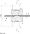
- Figure 1a shows the process steps a) to c) for preparing a joint 15 on a first component 10.
- the first component 10 is multi-layered and has two sheet-like components 12, 13 and an intermediate layer 14 arranged between the two components 12, 13.
- the intermediate layer is designed as a plastic-containing layer.
- the joining process In order to connect the first component 10 to a second component 11 (in Figure 1a not shown), the joining process must be designed in such a way that a joint 15 is prepared before the first component 10 is connected to a second component 11. It is essential here that the intermediate layer 14 is displaced in the area of the joint 15 so that contact is created between the two components 12, 13 in this area.
- the pressure means 26, 27 for exerting the pressure force in step b) can be, for example, electrode caps of a welding device. Furthermore, different tools can be used for the individual process steps a) to c). As in Figure 1a As shown, in this example the same tools, namely the pressure means 26, 27, are used for the process steps a) to c). For this purpose, the two pressure means 26, 27 have heating elements 29 and connections for connecting an electrical voltage 17.
- the two preheated pressure means 26, 27 are placed on the respective surface of a component 12, 13.
- the pressure means 26, 27 are warmed or heated to a temperature between 200°C and 500°C via the heating elements 29.
- a compressive force 16 is exerted on the components 12, 13 using the two pressure means 26, 27 until the intermediate layer 14 has been displaced in the region of the joint 15 to be prepared between the first component 12 and the second component 13 and contact is established between the two components 12, 13.
- an electrical voltage 17 is applied to the two pressure means 26, 27.
- An electrical current is thus conducted vertically through the two components 12, 13.
- the contact area between the two components 12, 13 is heated as a result of the resistance heating.
- the electrical voltage 17 is controlled in such a way that the temperature in the contact area between the two components 12, 13 does not exceed a predetermined temperature threshold 21.
- the two components 12, 13 are designed as metal sheets and have a melting temperature of approximately 1,530°C. To ensure that the two components 12, 13 are not welded in this area but are merely adhered to one another, the temperature threshold 21 is below the melting temperature of approximately 1,530°C of the two components 12, 13. This means that no weld nugget is formed in the area of the contact point due to the resistance heating.
- Figure 1b shows the area of the joint 15.
- the various areas 18, 19, 20 of the displaced intermediate layer 14 around the joint 15 are shown.
- the material of the intermediate layer 14 is completely displaced. Due to the resistance heating and the resulting heat flow through the material of the displaced intermediate layer 14, this material is thermally destroyed in a first area 18 to such an extent that it has lost its flowability.
- the second area 19 of the displaced intermediate layer 14 adjoins the first area 18. In this area, the material of the intermediate layer 14 is only thermally influenced.
- the third region 20 of the displaced intermediate layer 14 as well as in the region of the non-displaced intermediate layer 14, the material of the intermediate layer 14 is not damaged or affected.
- pressure means 26, 27 were used to prepare the joints such that only one recess 25 is arranged in the second component 13.
- the second component 11 can be arranged and connected to the first component 10, for example welded.
- a bolt 23 connected to the first component 10 is shown as the second component 11.
- the bolt 23 is thus arranged in the recess 25.
- a suitable pressure means 26 (not shown) was used to press the bolt 23 against the recess 25.
- Figure 1b shown) maintains a flat outer surface of the first component 10.
- the maximum width 42 of the joint 15 is greater than the maximum width 43 of the second component 11, namely the bolt 23.
- a pin-shaped second component 11, for example a bolt 23, usually has a diameter of between 1 mm and 14 mm. This diameter usually has a range between 3 mm and 8 mm.
- the length of a pin-shaped second component 11, for example a bolt 23, can be between 1 mm and 100 mm.
- the pin-shaped second component 11, for example the bolt 23, can have an external thread and/or an internal thread in some areas or over the entire length.
- FIGs 3a to 3c different forms of pressure means 26, 27 are shown for carrying out the process steps a) to c).
- the pressure means 26, 27 can in particular have different pressure surfaces 28.
- Both pressure means 26, 27 have convex pressure surfaces 28.
- a pressure means 26 has a flat or level pressure surface 28. This ensures that a surface of the first component 10 continues to maintain a flat or level surface after the joint 15 has been prepared.
- both pressure means 26, 27 could also have flat pressure surfaces 28. This could result in a joint, as in Figure 2c shown, generated.
- roller-shaped pressure means 26, 27 are shown. By means of such roller-shaped pressure means 26, 27, a web-like joint 15 can be arranged or prepared on the first component 10.
- Figure 4 shows a device 200 for joint preparation.
- the process steps a) to c) for preparing the joint 15 can be carried out with one device 200 or several or different devices.
- the device 200 has pressing tools for heating and displacing the intermediate layer 14, for example pressure means 26, 27.
- a welding system can be equipped with heating elements 29 in the electrodes 35, 36 for this purpose.
- the desired temperature at the pressure means 26, 27 can be regulated by means of thermocouples 39 that are also provided.
- the temperature-controlled pressure means 26, 27 are possible with all designs of conventional resistance welding systems, for example C-guns, X-guns, machine guns, stationary and portal systems. Water cooling of the electrodes can be dispensed with.
- the temperature profile between the pressure means 26, 27 and the base body, for example the gun base body can be influenced by the targeted use of copper alloys and chromium-nickel steels.
- the heat flow from a heating element 29 to the pressure means 26, 27, for example an electrode cap is promoted by components made of copper alloys (e.g. CuCr1Zr or CuNiSiCr).
- the heat flow from the heating element 29 into the base body of the device 200 and into other temperature-sensitive components of the device 200 can be reduced by components (e.g. the electrode arms of a resistance spot welding gun) made of a relatively poorly heat-conducting chromium-nickel steel.
- the device 200 can also be used for the method step d) for connecting the first component to a second component in the region of the joint 15 prepared in steps a) to c).
Landscapes
- Engineering & Computer Science (AREA)
- Mechanical Engineering (AREA)
- Physics & Mathematics (AREA)
- Plasma & Fusion (AREA)
- Connection Of Plates (AREA)
- Resistance Welding (AREA)
- Lining Or Joining Of Plastics Or The Like (AREA)
Claims (8)
- Procédé permettant d'assembler un premier composant (10) avec un second composant (11) en un point d'assemblage (15) du premier composant (10), dans lequel le premier composant (10) présente au moins un premier élément de construction (12) réalisé à plat, un second élément de construction (13) réalisé à plat et une couche intermédiaire (14) présentant de la matière plastique et disposée au moins par zones entre les deux éléments de construction (12, 13), dans lequel le procédé présente les étapes suivantes :a) chauffage du premier élément de construction (12) et/ou du second élément de construction (13) dans la zone du point d'assemblage (15) ; etb) exercice d'une force de pression (16) sur le premier élément de construction (12) et/ou le second élément de construction (13) dans la zone du point d'assemblage (15), jusqu'à ce que la couche intermédiaire (14) ait été déplacée dans la zone du point d'assemblage (15) entre le premier élément de construction (12) et le second élément de construction (13) et qu'un contact soit établi entre le premier élément de construction (12) et le second élément de construction (13) dans la zone du point d'assemblage (15) ; etc) application d'une tension électrique (17) au premier élément de construction (12) et au second élément de construction (13) dans la zone du point d'assemblage (15), jusqu'à ce que le premier élément de construction (12) et le second élément de construction adhèrent l'un à l'autre dans la zone du point d'assemblage (15) ; etd) liaison du premier composant (10) au second composant (11) dans la zone du point d'assemblage (15) ;caractérisé en ce
que, pendant l'étape c), une température dans la zone de contact entre le premier élément de construction (12) et le second élément de construction (13) ne s'élève pas au-dessus d'un seuil de température (21) prédéterminé, dans lequel le seuil de température (21) est inférieur au point de fusion d'un matériau du premier élément de construction (12) et inférieur au point de fusion d'un matériau du second élément de construction (13), dans lequel les étapes de procédé a) à c) sont désignées comme étapes de procédé pour la préparation des points d'assemblage, dans lequel l'étape d) comprend un processus d'assemblage en aval dans le temps entre le premier composant multicouche (10) et un autre, à savoir le second composant (11). - Procédé selon la revendication 1,
caractérisé en ce
que le seuil de température (21) prédéterminé est inférieur à 1600 °C, de préférence inférieur à 1530 °C, de manière particulièrement préférée inférieur à 1500 °C - Procédé selon la revendication 1 ou 2,
caractérisé en ce
que la tension électrique (17) est appliquée à l'étape c) jusqu'à ce que la couche intermédiaire (14) soit thermiquement détruite dans une première zone (18) adjacente au point d'assemblage (15) en raison d'un chauffage provoqué par un flux de courant électrique, de telle sorte que la couche intermédiaire (14) ne soit plus fluide même après refroidissement dans ladite première zone (18) - Procédé selon l'une des revendications précédentes,
caractérisé en ce
que l'on détecte à l'étape b) quand le contact entre le premier élément de construction (12) et le second élément de construction (13) est établi dans la zone du point d'assemblage (15), pour appliquer la tension électrique (17) à l'étape c). - Procédé selon la revendication 4,
caractérisé en ce
que la détection du contact entre le premier élément de construction (12) et le second élément de construction (13) est effectuée à l'aide d'une tension d'essai appliquée aux deux éléments de construction (12, 13) et/ou à l'aide d'une mesure de déplacement. - Procédé selon l'une des revendications précédentes,
caractérisé en ce
que les étapes a) à c) sont exécutées en continu le long d'une ligne prédéterminée du premier composant (10) afin de réaliser le point d'assemblage (15) en forme de bande. - Procédé selon l'une des revendications précédentes,
caractérisé en ce
que, à l'étape b), la force de pression (16) est exercée sur le premier élément de construction (12) de telle sorte qu'il se forme un creux (25) sur une surface du premier élément de construction (12) dans la zone du point d'assemblage (15), et la force de pression (16) est exercée sur le second élément de construction (13) de telle sorte qu'il reste une surface plane sur une surface du second élément de construction (13) dans la zone du point d'assemblage (15). - Procédé selon l'une des revendications précédentes,
caractérisé en ce
qu'à l'étape d), le second composant (11) est relié au premier composant (10) par soudage dans la zone du point d'assemblage (15) du premier composant (10).
Applications Claiming Priority (2)
| Application Number | Priority Date | Filing Date | Title |
|---|---|---|---|
| DE102014208708.2A DE102014208708A1 (de) | 2014-05-09 | 2014-05-09 | Verfahren und Vorrichtung zum Fügen eines Verbundblechbauteils mit einem weiteren Bauteil |
| PCT/EP2015/058642 WO2015169588A1 (fr) | 2014-05-09 | 2015-04-22 | Procédé et dispositif pour l'assemblage d'un élément structural en tôle composite avec un autre élément structural |
Publications (2)
| Publication Number | Publication Date |
|---|---|
| EP3140069A1 EP3140069A1 (fr) | 2017-03-15 |
| EP3140069B1 true EP3140069B1 (fr) | 2025-03-05 |
Family
ID=53039396
Family Applications (1)
| Application Number | Title | Priority Date | Filing Date |
|---|---|---|---|
| EP15719652.8A Active EP3140069B1 (fr) | 2014-05-09 | 2015-04-22 | Procédé et dispositif pour l'assemblage d'un élément structural en tôle composite avec un autre élément structural |
Country Status (4)
| Country | Link |
|---|---|
| EP (1) | EP3140069B1 (fr) |
| CN (1) | CN106715026B (fr) |
| DE (1) | DE102014208708A1 (fr) |
| WO (1) | WO2015169588A1 (fr) |
Families Citing this family (8)
| Publication number | Priority date | Publication date | Assignee | Title |
|---|---|---|---|---|
| DE102015100496A1 (de) | 2015-01-14 | 2016-07-14 | Thyssenkrupp Ag | Schweißelektrode, Verfahren und Vorrichtung zum Schweißen von Sandwichblechen |
| DE102015111381A1 (de) * | 2015-07-14 | 2017-01-19 | Dr. Ing. H.C. F. Porsche Aktiengesellschaft | Schweißelektrode für eine Kondensatorentladungsschweißvorrichtung und Kondensatorentladungsschweißvorrichtung |
| DE102016217395A1 (de) | 2016-09-13 | 2018-03-15 | Thyssenkrupp Ag | Heizelektrode |
| DE102017105192A1 (de) * | 2017-03-10 | 2018-09-13 | Thyssenkrupp Ag | Verfahren zum Verbinden eines Sandwich-Bauteils |
| CN108044224B (zh) * | 2017-11-23 | 2020-06-16 | 青岛武船重工有限公司 | 奥氏体不锈钢螺柱与铁素体结构钢间的电弧螺柱焊方法 |
| CN112676688B (zh) * | 2021-03-15 | 2021-06-04 | 中汽研(天津)汽车工程研究院有限公司 | 一种异质金属电阻点焊方法 |
| DE102021106365A1 (de) * | 2021-03-16 | 2022-09-22 | Bayerische Motoren Werke Aktiengesellschaft | Verfahren zum Fügen von Bauteilen sowie Bauteilverbindung |
| CN119457363A (zh) * | 2025-01-16 | 2025-02-18 | 天津力神聚元新能源科技有限公司 | 复合箔集流体、电极片、电芯及其制备方法和电池 |
Family Cites Families (13)
| Publication number | Priority date | Publication date | Assignee | Title |
|---|---|---|---|---|
| US3337711A (en) * | 1965-05-15 | 1967-08-22 | Janusz L A Garscia | Method of welding metal bodies separated by an adhesive layer |
| US4009362A (en) * | 1968-05-08 | 1977-02-22 | Otto Alfred Becker | Process and apparatus for welding sheet metal coated with layers |
| JPS6068180A (ja) * | 1983-09-26 | 1985-04-18 | Mitsui Petrochem Ind Ltd | 絶縁層を有した金属材料の溶接方法 |
| JPS61115687A (ja) * | 1984-11-10 | 1986-06-03 | Kobe Steel Ltd | 複合材料の溶接方法 |
| FR2638668B3 (fr) * | 1988-11-10 | 1990-09-07 | Lorraine Laminage | Procede et dispositif pour le soudage par resistance de toles, notamment de toles composites |
| FR2709083B1 (fr) * | 1993-08-16 | 1995-11-10 | Lorraine Laminage | Flan de tôle de structure multicouche à soudabilité et à emboutissabilité améliorée et procédé et dispositif de fabrication de ce type de flans de tôle. |
| JP3752830B2 (ja) * | 1998-03-31 | 2006-03-08 | マツダ株式会社 | 接合金属部材及び該部材の接合方法 |
| FR2796580B1 (fr) * | 1999-07-20 | 2001-09-21 | Aro | Procede de soudage electrique d'une piece sur une tole composite |
| DE10111567A1 (de) | 2001-03-10 | 2002-09-26 | Daimler Chrysler Ag | Verschweißbares mehrschichtiges Bauteil und Verfahren zu seiner Herstellung |
| DE102011052110A1 (de) * | 2011-07-25 | 2013-01-31 | Thyssenkrupp Steel Europe Ag | Leichtblechkonstruktion |
| DE102011109708A1 (de) | 2011-08-06 | 2013-02-07 | Volkswagen Aktiengesellschaft | Fügen von blechartigen Bauelementen mit Zwischenschicht aus thermoplastischem Kunststoff |
| DE102011054362A1 (de) | 2011-10-10 | 2013-04-11 | Thyssenkrupp Steel Europe Ag | Verbundblechteil mit metallischem Randbereich |
| DE102011117962A1 (de) * | 2011-11-07 | 2013-05-08 | Magna Steyr Fahrzeugtechnik Ag & Co. Kg | Werkzeug und Verfahren zum Fügen von Materiallagen |
-
2014
- 2014-05-09 DE DE102014208708.2A patent/DE102014208708A1/de not_active Withdrawn
-
2015
- 2015-04-22 CN CN201580024333.0A patent/CN106715026B/zh active Active
- 2015-04-22 EP EP15719652.8A patent/EP3140069B1/fr active Active
- 2015-04-22 WO PCT/EP2015/058642 patent/WO2015169588A1/fr not_active Ceased
Also Published As
| Publication number | Publication date |
|---|---|
| CN106715026B (zh) | 2020-05-19 |
| WO2015169588A1 (fr) | 2015-11-12 |
| DE102014208708A1 (de) | 2015-11-12 |
| EP3140069A1 (fr) | 2017-03-15 |
| CN106715026A (zh) | 2017-05-24 |
Similar Documents
| Publication | Publication Date | Title |
|---|---|---|
| EP3140069B1 (fr) | Procédé et dispositif pour l'assemblage d'un élément structural en tôle composite avec un autre élément structural | |
| WO2015169587A1 (fr) | Procédé et dispositif pour l'assemblage d'un élément structural en tôle composite avec un élément fonctionnel | |
| EP2739427B1 (fr) | Liaison de pièces de tôle ayant une couche intermédiaire en matière thermoplastique | |
| EP2900414B1 (fr) | Procédé pour relier des éléments à l'aide d'une pièce de jonction d'aide au soudage | |
| EP2679328B1 (fr) | Assemblage de deux partenaires d'assemblage au moyen d'une combinaison d'un soudage par résistance et d'un soudage par friction | |
| WO2015024698A1 (fr) | Procédé pour assembler au moins deux parties tôle | |
| EP2655004B1 (fr) | Soudage haute fréquence de tôles sandwich | |
| DE102016118109A1 (de) | Fügeverfahren zum vorlochfreien Verbinden von wenigstens einem ersten Bauteil mit einem zweiten Bauteil | |
| DE102010020569A1 (de) | Verfahren zum thermischen Fügen von zwei Bauelementen | |
| DE102016212622B4 (de) | Verfahren zum Fügen von Bauteilen | |
| WO2014161823A1 (fr) | Procédé de raccordement d'une cosse de câble tubulaire à un conducteur multibrins en aluminium | |
| WO2019154925A1 (fr) | Procédé et dispositif pour l'introduction d'un élément d'assemblage | |
| DE102019100651A1 (de) | Widerstandspunktschweißverfahren | |
| DE102010053608A1 (de) | Schweißverbindung | |
| DE102015216539A1 (de) | Verfahren zum Verbinden zweier Bauteile, Bauteileverbund, Verwendung eines Bauteileverbunds und Fügeelement zur Ausbildung eines Bauteileverbunds | |
| DE102016007698B4 (de) | Verfahren zur Herstellung eines Bauteilverbunds | |
| EP3433078A1 (fr) | Dispositif et procédé pour la réalisation ou la séparation d'une liaison d'au moins une pièce métallique ou céramique et d'au moins une pièce formée à partir de ou contenant un polymère thermoplastique | |
| DE102017212576B4 (de) | Verbindung eines metallischen Bauteils und eines Kunststoff-Bauteils | |
| DE102015107309A1 (de) | Fügebauteil und Fügeverfahren | |
| DE102018104701B4 (de) | Verfahren zur mechanischen Verbindung eines Werkstücks mit einem elektrisch leitfähigen Werkstück und Vorrichtung zur Durchführung des Verfahrens | |
| DE3149513A1 (de) | Verfahren und vorrichtung zur befestigung von platten auf blechen, profilen oder rohren sowie guss- und schmiedeteilen aus aluminium | |
| DE102018126914A1 (de) | Verfahren zum Herstellen wenigstens einer definierten Verbindungsschicht zwischen zwei Bauteilen aus unterschiedlichen Metallen | |
| DE102018115880A1 (de) | Verfahren zur stoßseitigen Profilgummiverbindung und Verbindungsschicht | |
| DE102017204829A1 (de) | Verfahren zum Verbinden von zwei Bauteilen | |
| DE102007012628B4 (de) | Mehrblechverbindung und Vorrichtung zum Herstellen derselben |
Legal Events
| Date | Code | Title | Description |
|---|---|---|---|
| STAA | Information on the status of an ep patent application or granted ep patent |
Free format text: STATUS: THE INTERNATIONAL PUBLICATION HAS BEEN MADE |
|
| PUAI | Public reference made under article 153(3) epc to a published international application that has entered the european phase |
Free format text: ORIGINAL CODE: 0009012 |
|
| STAA | Information on the status of an ep patent application or granted ep patent |
Free format text: STATUS: REQUEST FOR EXAMINATION WAS MADE |
|
| 17P | Request for examination filed |
Effective date: 20161209 |
|
| AK | Designated contracting states |
Kind code of ref document: A1 Designated state(s): AL AT BE BG CH CY CZ DE DK EE ES FI FR GB GR HR HU IE IS IT LI LT LU LV MC MK MT NL NO PL PT RO RS SE SI SK SM TR |
|
| AX | Request for extension of the european patent |
Extension state: BA ME |
|
| DAV | Request for validation of the european patent (deleted) | ||
| DAX | Request for extension of the european patent (deleted) | ||
| STAA | Information on the status of an ep patent application or granted ep patent |
Free format text: STATUS: EXAMINATION IS IN PROGRESS |
|
| 17Q | First examination report despatched |
Effective date: 20210511 |
|
| GRAP | Despatch of communication of intention to grant a patent |
Free format text: ORIGINAL CODE: EPIDOSNIGR1 |
|
| STAA | Information on the status of an ep patent application or granted ep patent |
Free format text: STATUS: GRANT OF PATENT IS INTENDED |
|
| INTG | Intention to grant announced |
Effective date: 20241105 |
|
| GRAS | Grant fee paid |
Free format text: ORIGINAL CODE: EPIDOSNIGR3 |
|
| GRAA | (expected) grant |
Free format text: ORIGINAL CODE: 0009210 |
|
| STAA | Information on the status of an ep patent application or granted ep patent |
Free format text: STATUS: THE PATENT HAS BEEN GRANTED |
|
| AK | Designated contracting states |
Kind code of ref document: B1 Designated state(s): AL AT BE BG CH CY CZ DE DK EE ES FI FR GB GR HR HU IE IS IT LI LT LU LV MC MK MT NL NO PL PT RO RS SE SI SK SM TR |
|
| REG | Reference to a national code |
Ref country code: GB Ref legal event code: FG4D Free format text: NOT ENGLISH |
|
| REG | Reference to a national code |
Ref country code: CH Ref legal event code: EP |
|
| REG | Reference to a national code |
Ref country code: DE Ref legal event code: R096 Ref document number: 502015017034 Country of ref document: DE |
|
| REG | Reference to a national code |
Ref country code: IE Ref legal event code: FG4D Free format text: LANGUAGE OF EP DOCUMENT: GERMAN |
|
| P01 | Opt-out of the competence of the unified patent court (upc) registered |
Free format text: CASE NUMBER: APP_9572/2025 Effective date: 20250226 |
|
| PG25 | Lapsed in a contracting state [announced via postgrant information from national office to epo] |
Ref country code: RS Free format text: LAPSE BECAUSE OF FAILURE TO SUBMIT A TRANSLATION OF THE DESCRIPTION OR TO PAY THE FEE WITHIN THE PRESCRIBED TIME-LIMIT Effective date: 20250605 |
|
| PG25 | Lapsed in a contracting state [announced via postgrant information from national office to epo] |
Ref country code: FI Free format text: LAPSE BECAUSE OF FAILURE TO SUBMIT A TRANSLATION OF THE DESCRIPTION OR TO PAY THE FEE WITHIN THE PRESCRIBED TIME-LIMIT Effective date: 20250305 |
|
| PGFP | Annual fee paid to national office [announced via postgrant information from national office to epo] |
Ref country code: DE Payment date: 20250430 Year of fee payment: 11 |
|
| REG | Reference to a national code |
Ref country code: NL Ref legal event code: MP Effective date: 20250305 |
|
| PG25 | Lapsed in a contracting state [announced via postgrant information from national office to epo] |
Ref country code: ES Free format text: LAPSE BECAUSE OF FAILURE TO SUBMIT A TRANSLATION OF THE DESCRIPTION OR TO PAY THE FEE WITHIN THE PRESCRIBED TIME-LIMIT Effective date: 20250305 |
|
| REG | Reference to a national code |
Ref country code: LT Ref legal event code: MG9D |
|
| PG25 | Lapsed in a contracting state [announced via postgrant information from national office to epo] |
Ref country code: NO Free format text: LAPSE BECAUSE OF FAILURE TO SUBMIT A TRANSLATION OF THE DESCRIPTION OR TO PAY THE FEE WITHIN THE PRESCRIBED TIME-LIMIT Effective date: 20250605 |
|
| PG25 | Lapsed in a contracting state [announced via postgrant information from national office to epo] |
Ref country code: HR Free format text: LAPSE BECAUSE OF FAILURE TO SUBMIT A TRANSLATION OF THE DESCRIPTION OR TO PAY THE FEE WITHIN THE PRESCRIBED TIME-LIMIT Effective date: 20250305 |
|
| PG25 | Lapsed in a contracting state [announced via postgrant information from national office to epo] |
Ref country code: LV Free format text: LAPSE BECAUSE OF FAILURE TO SUBMIT A TRANSLATION OF THE DESCRIPTION OR TO PAY THE FEE WITHIN THE PRESCRIBED TIME-LIMIT Effective date: 20250305 |
|
| PG25 | Lapsed in a contracting state [announced via postgrant information from national office to epo] |
Ref country code: GR Free format text: LAPSE BECAUSE OF FAILURE TO SUBMIT A TRANSLATION OF THE DESCRIPTION OR TO PAY THE FEE WITHIN THE PRESCRIBED TIME-LIMIT Effective date: 20250606 Ref country code: BG Free format text: LAPSE BECAUSE OF FAILURE TO SUBMIT A TRANSLATION OF THE DESCRIPTION OR TO PAY THE FEE WITHIN THE PRESCRIBED TIME-LIMIT Effective date: 20250305 |
|
| PG25 | Lapsed in a contracting state [announced via postgrant information from national office to epo] |
Ref country code: NL Free format text: LAPSE BECAUSE OF FAILURE TO SUBMIT A TRANSLATION OF THE DESCRIPTION OR TO PAY THE FEE WITHIN THE PRESCRIBED TIME-LIMIT Effective date: 20250305 |
|
| PG25 | Lapsed in a contracting state [announced via postgrant information from national office to epo] |
Ref country code: SE Free format text: LAPSE BECAUSE OF FAILURE TO SUBMIT A TRANSLATION OF THE DESCRIPTION OR TO PAY THE FEE WITHIN THE PRESCRIBED TIME-LIMIT Effective date: 20250305 |
|
| PG25 | Lapsed in a contracting state [announced via postgrant information from national office to epo] |
Ref country code: SM Free format text: LAPSE BECAUSE OF FAILURE TO SUBMIT A TRANSLATION OF THE DESCRIPTION OR TO PAY THE FEE WITHIN THE PRESCRIBED TIME-LIMIT Effective date: 20250305 |
|
| PG25 | Lapsed in a contracting state [announced via postgrant information from national office to epo] |
Ref country code: PT Free format text: LAPSE BECAUSE OF FAILURE TO SUBMIT A TRANSLATION OF THE DESCRIPTION OR TO PAY THE FEE WITHIN THE PRESCRIBED TIME-LIMIT Effective date: 20250707 |
|
| PG25 | Lapsed in a contracting state [announced via postgrant information from national office to epo] |
Ref country code: IT Free format text: LAPSE BECAUSE OF FAILURE TO SUBMIT A TRANSLATION OF THE DESCRIPTION OR TO PAY THE FEE WITHIN THE PRESCRIBED TIME-LIMIT Effective date: 20250305 Ref country code: PL Free format text: LAPSE BECAUSE OF FAILURE TO SUBMIT A TRANSLATION OF THE DESCRIPTION OR TO PAY THE FEE WITHIN THE PRESCRIBED TIME-LIMIT Effective date: 20250305 |
|
| PG25 | Lapsed in a contracting state [announced via postgrant information from national office to epo] |
Ref country code: EE Free format text: LAPSE BECAUSE OF FAILURE TO SUBMIT A TRANSLATION OF THE DESCRIPTION OR TO PAY THE FEE WITHIN THE PRESCRIBED TIME-LIMIT Effective date: 20250305 Ref country code: CZ Free format text: LAPSE BECAUSE OF FAILURE TO SUBMIT A TRANSLATION OF THE DESCRIPTION OR TO PAY THE FEE WITHIN THE PRESCRIBED TIME-LIMIT Effective date: 20250305 |
|
| PG25 | Lapsed in a contracting state [announced via postgrant information from national office to epo] |
Ref country code: RO Free format text: LAPSE BECAUSE OF FAILURE TO SUBMIT A TRANSLATION OF THE DESCRIPTION OR TO PAY THE FEE WITHIN THE PRESCRIBED TIME-LIMIT Effective date: 20250305 |
|
| PG25 | Lapsed in a contracting state [announced via postgrant information from national office to epo] |
Ref country code: SK Free format text: LAPSE BECAUSE OF FAILURE TO SUBMIT A TRANSLATION OF THE DESCRIPTION OR TO PAY THE FEE WITHIN THE PRESCRIBED TIME-LIMIT Effective date: 20250305 |
|
| PG25 | Lapsed in a contracting state [announced via postgrant information from national office to epo] |
Ref country code: IS Free format text: LAPSE BECAUSE OF FAILURE TO SUBMIT A TRANSLATION OF THE DESCRIPTION OR TO PAY THE FEE WITHIN THE PRESCRIBED TIME-LIMIT Effective date: 20250705 |
|
| REG | Reference to a national code |
Ref country code: CH Ref legal event code: H13 Free format text: ST27 STATUS EVENT CODE: U-0-0-H10-H13 (AS PROVIDED BY THE NATIONAL OFFICE) Effective date: 20251125 |
|
| REG | Reference to a national code |
Ref country code: DE Ref legal event code: R097 Ref document number: 502015017034 Country of ref document: DE |
|
| PG25 | Lapsed in a contracting state [announced via postgrant information from national office to epo] |
Ref country code: LU Free format text: LAPSE BECAUSE OF NON-PAYMENT OF DUE FEES Effective date: 20250422 |
|
| PG25 | Lapsed in a contracting state [announced via postgrant information from national office to epo] |
Ref country code: MC Free format text: LAPSE BECAUSE OF FAILURE TO SUBMIT A TRANSLATION OF THE DESCRIPTION OR TO PAY THE FEE WITHIN THE PRESCRIBED TIME-LIMIT Effective date: 20250305 |
|
| REG | Reference to a national code |
Ref country code: BE Ref legal event code: MM Effective date: 20250430 |
|
| PLBE | No opposition filed within time limit |
Free format text: ORIGINAL CODE: 0009261 |
|
| STAA | Information on the status of an ep patent application or granted ep patent |
Free format text: STATUS: NO OPPOSITION FILED WITHIN TIME LIMIT |
|
| PG25 | Lapsed in a contracting state [announced via postgrant information from national office to epo] |
Ref country code: DK Free format text: LAPSE BECAUSE OF FAILURE TO SUBMIT A TRANSLATION OF THE DESCRIPTION OR TO PAY THE FEE WITHIN THE PRESCRIBED TIME-LIMIT Effective date: 20250305 |
|
| REG | Reference to a national code |
Ref country code: CH Ref legal event code: L10 Free format text: ST27 STATUS EVENT CODE: U-0-0-L10-L00 (AS PROVIDED BY THE NATIONAL OFFICE) Effective date: 20260114 |
|
| PG25 | Lapsed in a contracting state [announced via postgrant information from national office to epo] |
Ref country code: BE Free format text: LAPSE BECAUSE OF NON-PAYMENT OF DUE FEES Effective date: 20250430 |
|
| PG25 | Lapsed in a contracting state [announced via postgrant information from national office to epo] |
Ref country code: CH Free format text: LAPSE BECAUSE OF NON-PAYMENT OF DUE FEES Effective date: 20250430 |
|
| 26N | No opposition filed |
Effective date: 20251208 |
|
| GBPC | Gb: european patent ceased through non-payment of renewal fee |
Effective date: 20250605 |
|
| PG25 | Lapsed in a contracting state [announced via postgrant information from national office to epo] |
Ref country code: GB Free format text: LAPSE BECAUSE OF NON-PAYMENT OF DUE FEES Effective date: 20250605 |
|
| PG25 | Lapsed in a contracting state [announced via postgrant information from national office to epo] |
Ref country code: IE Free format text: LAPSE BECAUSE OF NON-PAYMENT OF DUE FEES Effective date: 20250422 |
|
| PG25 | Lapsed in a contracting state [announced via postgrant information from national office to epo] |
Ref country code: FR Free format text: LAPSE BECAUSE OF NON-PAYMENT OF DUE FEES Effective date: 20250505 |