EP3140434B1 - Couche de diffusion de gaz, cellule électrolytique pem équipée d'une telle couche de diffusion de gaz, ainsi qu'électrolyseur - Google Patents
Couche de diffusion de gaz, cellule électrolytique pem équipée d'une telle couche de diffusion de gaz, ainsi qu'électrolyseur Download PDFInfo
- Publication number
- EP3140434B1 EP3140434B1 EP15728864.8A EP15728864A EP3140434B1 EP 3140434 B1 EP3140434 B1 EP 3140434B1 EP 15728864 A EP15728864 A EP 15728864A EP 3140434 B1 EP3140434 B1 EP 3140434B1
- Authority
- EP
- European Patent Office
- Prior art keywords
- gas diffusion
- diffusion layer
- spring
- spring component
- component
- Prior art date
- Legal status (The legal status is an assumption and is not a legal conclusion. Google has not performed a legal analysis and makes no representation as to the accuracy of the status listed.)
- Active
Links
Images
Classifications
-
- C—CHEMISTRY; METALLURGY
- C25—ELECTROLYTIC OR ELECTROPHORETIC PROCESSES; APPARATUS THEREFOR
- C25B—ELECTROLYTIC OR ELECTROPHORETIC PROCESSES FOR THE PRODUCTION OF COMPOUNDS OR NON-METALS; APPARATUS THEREFOR
- C25B1/00—Electrolytic production of inorganic compounds or non-metals
- C25B1/01—Products
- C25B1/02—Hydrogen or oxygen
- C25B1/04—Hydrogen or oxygen by electrolysis of water
-
- C—CHEMISTRY; METALLURGY
- C25—ELECTROLYTIC OR ELECTROPHORETIC PROCESSES; APPARATUS THEREFOR
- C25B—ELECTROLYTIC OR ELECTROPHORETIC PROCESSES FOR THE PRODUCTION OF COMPOUNDS OR NON-METALS; APPARATUS THEREFOR
- C25B11/00—Electrodes; Manufacture thereof not otherwise provided for
- C25B11/02—Electrodes; Manufacture thereof not otherwise provided for characterised by shape or form
- C25B11/03—Electrodes; Manufacture thereof not otherwise provided for characterised by shape or form perforated or foraminous
- C25B11/031—Porous electrodes
-
- C—CHEMISTRY; METALLURGY
- C25—ELECTROLYTIC OR ELECTROPHORETIC PROCESSES; APPARATUS THEREFOR
- C25B—ELECTROLYTIC OR ELECTROPHORETIC PROCESSES FOR THE PRODUCTION OF COMPOUNDS OR NON-METALS; APPARATUS THEREFOR
- C25B11/00—Electrodes; Manufacture thereof not otherwise provided for
- C25B11/02—Electrodes; Manufacture thereof not otherwise provided for characterised by shape or form
- C25B11/036—Bipolar electrodes
-
- C—CHEMISTRY; METALLURGY
- C25—ELECTROLYTIC OR ELECTROPHORETIC PROCESSES; APPARATUS THEREFOR
- C25B—ELECTROLYTIC OR ELECTROPHORETIC PROCESSES FOR THE PRODUCTION OF COMPOUNDS OR NON-METALS; APPARATUS THEREFOR
- C25B9/00—Cells or assemblies of cells; Constructional parts of cells; Assemblies of constructional parts, e.g. electrode-diaphragm assemblies; Process-related cell features
- C25B9/17—Cells comprising dimensionally-stable non-movable electrodes; Assemblies of constructional parts thereof
- C25B9/19—Cells comprising dimensionally-stable non-movable electrodes; Assemblies of constructional parts thereof with diaphragms
- C25B9/23—Cells comprising dimensionally-stable non-movable electrodes; Assemblies of constructional parts thereof with diaphragms comprising ion-exchange membranes in or on which electrode material is embedded
-
- C—CHEMISTRY; METALLURGY
- C25—ELECTROLYTIC OR ELECTROPHORETIC PROCESSES; APPARATUS THEREFOR
- C25B—ELECTROLYTIC OR ELECTROPHORETIC PROCESSES FOR THE PRODUCTION OF COMPOUNDS OR NON-METALS; APPARATUS THEREFOR
- C25B9/00—Cells or assemblies of cells; Constructional parts of cells; Assemblies of constructional parts, e.g. electrode-diaphragm assemblies; Process-related cell features
- C25B9/70—Assemblies comprising two or more cells
- C25B9/73—Assemblies comprising two or more cells of the filter-press type
-
- C—CHEMISTRY; METALLURGY
- C25—ELECTROLYTIC OR ELECTROPHORETIC PROCESSES; APPARATUS THEREFOR
- C25B—ELECTROLYTIC OR ELECTROPHORETIC PROCESSES FOR THE PRODUCTION OF COMPOUNDS OR NON-METALS; APPARATUS THEREFOR
- C25B9/00—Cells or assemblies of cells; Constructional parts of cells; Assemblies of constructional parts, e.g. electrode-diaphragm assemblies; Process-related cell features
- C25B9/70—Assemblies comprising two or more cells
- C25B9/73—Assemblies comprising two or more cells of the filter-press type
- C25B9/75—Assemblies comprising two or more cells of the filter-press type having bipolar electrodes
-
- H—ELECTRICITY
- H01—ELECTRIC ELEMENTS
- H01M—PROCESSES OR MEANS, e.g. BATTERIES, FOR THE DIRECT CONVERSION OF CHEMICAL ENERGY INTO ELECTRICAL ENERGY
- H01M4/00—Electrodes
- H01M4/86—Inert electrodes with catalytic activity, e.g. for fuel cells
- H01M4/88—Processes of manufacture
- H01M4/8803—Supports for the deposition of the catalytic active composition
- H01M4/8807—Gas diffusion layers
-
- H—ELECTRICITY
- H01—ELECTRIC ELEMENTS
- H01M—PROCESSES OR MEANS, e.g. BATTERIES, FOR THE DIRECT CONVERSION OF CHEMICAL ENERGY INTO ELECTRICAL ENERGY
- H01M8/00—Fuel cells; Manufacture thereof
- H01M8/02—Details
- H01M8/0202—Collectors; Separators, e.g. bipolar separators; Interconnectors
- H01M8/023—Porous and characterised by the material
- H01M8/0241—Composites
- H01M8/0245—Composites in the form of layered or coated products
-
- Y—GENERAL TAGGING OF NEW TECHNOLOGICAL DEVELOPMENTS; GENERAL TAGGING OF CROSS-SECTIONAL TECHNOLOGIES SPANNING OVER SEVERAL SECTIONS OF THE IPC; TECHNICAL SUBJECTS COVERED BY FORMER USPC CROSS-REFERENCE ART COLLECTIONS [XRACs] AND DIGESTS
- Y02—TECHNOLOGIES OR APPLICATIONS FOR MITIGATION OR ADAPTATION AGAINST CLIMATE CHANGE
- Y02E—REDUCTION OF GREENHOUSE GAS [GHG] EMISSIONS, RELATED TO ENERGY GENERATION, TRANSMISSION OR DISTRIBUTION
- Y02E60/00—Enabling technologies; Technologies with a potential or indirect contribution to GHG emissions mitigation
- Y02E60/30—Hydrogen technology
- Y02E60/36—Hydrogen production from non-carbon containing sources, e.g. by water electrolysis
-
- Y—GENERAL TAGGING OF NEW TECHNOLOGICAL DEVELOPMENTS; GENERAL TAGGING OF CROSS-SECTIONAL TECHNOLOGIES SPANNING OVER SEVERAL SECTIONS OF THE IPC; TECHNICAL SUBJECTS COVERED BY FORMER USPC CROSS-REFERENCE ART COLLECTIONS [XRACs] AND DIGESTS
- Y02—TECHNOLOGIES OR APPLICATIONS FOR MITIGATION OR ADAPTATION AGAINST CLIMATE CHANGE
- Y02E—REDUCTION OF GREENHOUSE GAS [GHG] EMISSIONS, RELATED TO ENERGY GENERATION, TRANSMISSION OR DISTRIBUTION
- Y02E60/00—Enabling technologies; Technologies with a potential or indirect contribution to GHG emissions mitigation
- Y02E60/30—Hydrogen technology
- Y02E60/50—Fuel cells
Definitions
- the invention relates to a gas diffusion layer for an electrochemical cell, in particular for a PEM electrolysis cell.
- the invention further relates to an electrochemical cell, in particular a PEM electrolysis cell or galvanic cell with such a gas diffusion layer and an electrolyzer.
- Electrochemical cells are well known and are divided into galvanic cells and electrolysis cells.
- An electrolytic cell is a device in which an electric current enforces a chemical reaction, wherein at least a portion of electrical energy is converted into chemical energy.
- a galvanic cell is a device - complementary to the electrolysis cell - for the spontaneous conversion of chemical into electrical energy.
- a known device of such a galvanic cell is e.g. a fuel cell.
- the core of a technical electrolysis plant is the electrolysis cell, comprising two electrodes and one electrolyte.
- the electrolyte consists of a proton-conducting membrane on which the electrodes are located on both sides.
- the unit of membrane and electrodes is referred to as MEA (Membrane Electrode Assembly).
- MEA Membrane Electrode Assembly
- the electrodes are in the assembled state of an electrolysis stack contacted from a plurality of electrolytic cells via a gas diffusion layer of so-called bipolar plates, wherein the bipolar plates separate the individual electrolytic cells of the stack from each other.
- the O 2 side of the electrolysis cell corresponds to the positive pole and the H 2 side corresponds to the negative pole, separated by the membrane-electrode unit located therebetween.
- the PEM electrolysis cell is fed on the O 2 side with demineralized water, which is decomposed at the anode into oxygen gas and protons (H + ).
- the protons migrate through the electrolyte membrane and recombine at the cathode (H2 side) to hydrogen gas.
- the gas diffusion layer adjacent to the electrodes ensures, in addition to the electrode contacting, the optimum distribution of water (and thus the wetting of the membrane) as well as the removal of the product gases. Therefore, what is needed as the gas diffusion layer is an electrically conductive, porous element with good permanent contacting of the electrode. As an additional requirement should be compensated if necessary in the electrolyzer building tolerances to allow a uniform contact of the MEA in each case of tolerance.
- sintered metal discs have been used as the gas diffusion layer in the rule. Although these meet the requirements for electrical conductivity and porosity, an additional tolerance compensation of the components of the electrolysis cell on both sides of the gas diffusion layer is not possible. In addition, the manufacturing cost of such discs are comparatively high and it is due to the size due to the required compression pressures in the production of such discs before a size restriction. In addition, distortion problems arise with large components, which are difficult to control.
- gas diffusion electrodes with spring elements for making an electrical contact in alkaline Electrolyzers is eg in the WO 2007/080193 A2 and the EP 2436804 A1 described.
- US 2003/188966 A1 describes another spring component for an electrolytic cell, which is arranged between a partition wall and a cathode.
- the spring component includes a plurality of leaf spring elements that abut the cathode to conform evenly.
- the invention is based on the object, possibly resulting component tolerances in an electrochemical cell, in particular in an electrolytic cell or galvanic cell, in particular in the field of bipolar plates, compensate.
- a gas diffusion layer for attachment between a bipolar plate and an electrode of an electrochemical cell comprising at least two layers superimposed layers, wherein one of the layers is formed as a spring component with a progressive spring characteristic.
- the object is further achieved according to the invention by an electrochemical cell, in particular by a PEM electrolysis cell, with such a gas diffusion layer.
- the object is further achieved according to the invention by an electrolyzer with such a PEM electrolysis cell.
- gas diffusion layer can be transferred analogously to the electrochemical cell, the galvanic cell, in particular the fuel cell, the PEM electrolysis cell and / or the electrolyzer.
- the invention is based on the recognition that it is ensured by a progressive spring behavior that the contact pressure in all tolerance positions of the adjacent components is sufficient.
- the implementation of a progressive spring behavior in a gas diffusion layer is effected by the geometry of the spring component.
- spring component is meant a layer or layer of the gas diffusion layer which has elastically restoring behavior, i. under load gives and returns to relief in the original shape.
- a spring characteristic shows the force-displacement curve of a spring, i.
- the spring characteristic in the form of a diagram provides information about how efficient the force-displacement ratio of a spring is.
- a progressive spring characteristic has the characteristic that it shows smaller and smaller steps on the spring travel with uniform load steps. With the progressive characteristic, the applied force increases in relation to the distance traveled. As alternatives there are the linear and the degressive spring characteristic.
- the gas diffusion layer of the electrochemical cell comprises at least three layers, that is to say inner and outer layers. It has proved to be particularly advantageous if the spring component forms an outer layer of the gas diffusion layer.
- An "outer layer” is provided for abutment with a component adjacent to the gas diffusion layer.
- outer layer is understood to mean that in the case of more than two layers, an outer layer, in particular directly adjacent to the bipolar plate, is designed as a spring component with a progressive spring characteristic.
- a spring component with a progressive spring characteristic as a gas diffusion layer has the significant advantages that in the range of normal contact pressure (about 5-25 bar) large deformations of the spring component can be achieved, so that large component tolerances are compensated; when overloaded, the additional spring travel is again low, so that the spring component withstands high pressures. Thus, too much plastic deformation of the spring component is prevented at a load significantly above the operating contact pressure.
- the suspension serves on the one hand to produce the electrical contact between the MEA and the bipolar plate, which is already guaranteed at a low contact pressure.
- the contact pressure ensures a uniform and areal contact with the MEA.
- the spring component pre-distributes the inflowing water. Furthermore, the electric current flow is given via the spring component.
- the at least two layers layered on top of one another preferably differ from one another in terms of their construction and / or composition. This is due in particular to the functionality of the layers.
- the one layer is located on the bipolar plate and the other is located on an electrode. Accordingly different are the properties and thus the construction or composition of both layers. The same applies if one or more intermediate layers are between the two outer layers.
- the gas diffusion layer comprises three layers: a contacting component, a diffusion component and the spring component.
- the internal contacting component serves to uniformly contact the gas diffusion layer to the electrode. Therefore, the use of fine materials such as fleece or very finely perforated sheet is recommended.
- the middle diffusion component serves to remove emerging gas, wherein the entire electric current flow passes through this component.
- the outer spring component ensures, as already explained, in the first place the most stable contact pressure regardless of the tolerance position of the adjacent components.
- the spring component is designed such that the spring characteristic is subdivided into at least two, in particular three areas with different course.
- the spring component is characterized in the region of the largest contact pressure by a maximum elastic deformation.
- Maximum elastic deformation here means the boundary between an elastic and purely plastic behavior of the spring component.
- a partially elastic and partially plastic behavior of the spring component likewise falls below the maximum elastic deformation.
- the maximum elastic deformation of the spring component is reached at a contact pressure of about 50 bar. About 50 bar, the spring behaves purely plastic, i. the deformation at this load and above is irreversible.
- the spring component is preferably designed such that at a contact pressure to 5 bar deformation of the spring component is present, which is up to 60%, in particular up to 80% based on the maximum elastic deformation.
- the spring component is preferably designed such that at a contact pressure between 5 bar and 25 bar there is a deformation of the spring component (12a, 12b, 12c), which is between 60% and 90% in relation to a maximum elastic deformation.
- the spring component is formed of an electrically conductive material, in particular of stainless steel, titanium, niobium, tantalum and / or nickel.
- an electrically conductive material in particular of stainless steel, titanium, niobium, tantalum and / or nickel.
- Such a composition of the spring component allows in particular their use as a power distributor.
- the spring component is formed in the manner of a profiled sheet. Such a configuration is characterized by a comparatively easy production.
- the spring component is designed in the manner of a braid.
- the spring properties can be easily varied by the type and density of the braid.
- the spring component comprises one or more spirals.
- the spring properties are defined by the design and arrangement of the spirals.
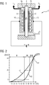
- FIG. 1 schematically the construction of an electrochemical cell 2 is shown, which is designed as a PEM electrolysis cell.
- the electrochemical cell 2 is part of an electrolyzer not shown here in detail for the splitting of water by electric current for the production of hydrogen and oxygen.
- the electrochemical cell 2 comprises an electrolyte consisting of a proton-conducting membrane 4 (proton exchange membrane, PEM) on which the electrodes 6a, 6b are located on both sides.
- the membrane-electrode assembly is referred to as the membrane-electrode assembly (MEA).
- 6a denotes a cathode
- 6b denotes an anode.
- a gas diffusion layer 8 is applied at each of the electrodes 6a, 6b.
- the gas diffusion layers 8 are contacted by so-called bipolar plates 10 which, in the assembled state of an electrolysis stack, separate from one another a plurality of individual electrolysis cells 2.
- the electrochemical cell 2 is supplied with water which is decomposed at the anode 6b into oxygen gas O 2 and proton H + .
- the protons H + migrate through the electrolyte membrane 4 in the direction of the cathode 6a. On the cathode side, they recombine to hydrogen gas H 2 .
- the electrochemical cell 2 is designed as a galvanic cell or fuel cell designed to generate electricity.
- the gas diffusion layers 8 of electrochemical cells 2 formed in this way are analogous to those in FIG FIG. 1 to be modified electrolysis cell. Without restricting generality, reference will therefore be made below by way of example to an electrochemical cell 2 designed as an electrolytic cell.
- the gas diffusion layer 8 By the gas diffusion layer 8 an optimal distribution of the water and the removal of the product gases are ensured.
- the gas diffusion layers 8 serve in accordance with the supply of reactants to the respective electrodes. It is essential here that the gas diffusion layer 8 is in any case permeable to the gaseous products or educts.
- the gas diffusion layer 8 also serves, in particular in the case of an electrolysis cell, as a current distributor. For these reasons, the gas diffusion layer 8 is formed of an electrically conductive porous material.
- the gas diffusion layer 8 therefore contains layers stacked on top of one another, wherein an outer layer as a spring component 12a, 12b, 12c (see FIG 3 to 9 ) is formed, which has a progressive spring characteristic.
- the gas diffusion layer 8 comprises in particular a contacting component shown, a diffusion component and the spring component, which are different from each other differ in their structure and / or composition.
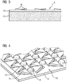
- FIG. 2 Two exemplary progressive spring characteristics K1 and K2 are shown. On the x-axis with S is the spring travel, and on the y-axis with F is the spring force. How out FIG. 2 As can be seen, the spring characteristics are divided into three areas.
- a maximum elastic deformation V max which is approximately 50 bar in the illustrated embodiment, represents the transition point between the elastic and the plastic curve of the spring characteristic and between the elastic and the plastic behavior of the spring. Right of the maximum elastic deformation V max ( ⁇ 100%) is a purely plastic deformation of the spring.
- the spring component deforms relatively strong at a relatively low contact pressure up to 5 bar, in particular, a deformation of the spring characteristic K1 between 20% and 30% and the spring characteristic K2 even over 60%.
- a second region II at a contact pressure between 5 bar and 25 bar is the deformation of the spring component between about 60% and about 90% based on the maximum elastic deformation V max .
- the spring component is also designed such that only a small deformation takes place at a contact pressure of over 25 bar, so that the part of the normalized spring travel S between 60% and 100% for K1 and between about 85% and 100% for K2 covered is.
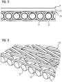
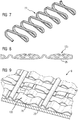
- a first embodiment of a gas diffusion layer 8 with a spring component 12a is shown. It comprises a sheet 14 with cut out at the surface, curved triangles 16, which give the sheet 14 its resilient behavior.
- the spring behavior of such a spring component 12a is progressive, but must be mechanically limited be in order to avoid excessive plastic deformation of the sheet 14.
- this is done by spacers 18 which are embossed between the triangles 16.
- the spacers 18 are substantially stiffer than the upwardly bent triangles 16, so that the spring characteristic of the spring component 12 a rises sharply as soon as the spacers 18 are brought into abutment with the adjacent bipolar plate 10.
- the gas diffusion layer 8 additionally comprises a contact-making component 19 formed from a nonwoven, which in the assembled state rests against an electrode 6a, 6b.
- FIG. 6 shows a second embodiment of a gas diffusion layer 8 with a further spring component 12b.
- the spring component 12b in this case comprises a spiral braid.
- the spiral braid comprises transverse bars 20 arranged one behind the other around which several spirals 22 are wound.
- FIG. 7 In addition, a single spiral 22 is shown, which forms the basis for the spring action of the braid.
- the spiral braid 12 b is formed when spirals 22 with the same geometry but different winding direction are alternately pushed into each other and connected by the transverse rods 20.
- the transverse rods 20 are made of plastic, for example.
- the spirals 22 are made of an electrically conductive material such as stainless steel, titanium, niobium, tantalum or nickel.
- cover layer 24 can be seen, which assumes the function of a contacting component 19 of the gas diffusion layer 8.
- the cover layer 24 is formed here from a layer of expanded metal or other porous and mechanically stable materials. Also conceivable, for example, are a fleece on a wire mesh, metal foam or a sintered metal disc.
- a third embodiment of the gas diffusion layer 8 is shown with a third spring component 12c.
- the spring component 12c is in the manner of a Corrugated sheet with alternately opposing curl pronounced. This form has the significant advantage that at the same time a guidance of the flow in the indicated direction S takes place.
- the suspension is here in three stages progressively rising from a very soft spring to a stop-like behavior (see FIG. 2 ).
- By the reference numeral 26 are in 8 and FIG. 9 Marked points that are pinned to an expanded metal.
- the hatched area 28 in FIG. 9 in this case represents a cover layer 24 or contacting component 19, which is directed to one of the electrodes 6a, 6b.
- the spring component 12c is formed substantially flat.
- a plurality of elastic portions of the spring component 12c are inclined with respect to a lateral direction extending substantially perpendicular to the surface extent (FIG. FIG. 8 ) are arranged at different distances to provide the progressive spring characteristic. It is thus achieved that with small deflections only a few, outer sections of the spring component 12c are deformed. For larger deflections increases both the deformation and the number of deformed portions of the spring component 12c, resulting in a non-linear increase in the force required for deformation, thus a progressive spring characteristic results.
- All of the above-described spring components 12a, 12b, 12c and gas diffusion layers 8 have the property that they compensate for the resulting component tolerances in the electrolyzer, to allow uniform contact of the membrane-electrode assembly in each case of tolerance. Due to the progressive spring characteristic of the spring components 12a, 12b, 12c, a one-sided excessive deformation of the gas diffusion layer 8 is prevented in the event of overload. In all embodiments is also conceivable between the spring component 12a, 12b, 12c and the contacting component 19, 24, 28 to attach a porous diffusion component not shown here in detail.
Landscapes
- Chemical & Material Sciences (AREA)
- Electrochemistry (AREA)
- Engineering & Computer Science (AREA)
- Chemical Kinetics & Catalysis (AREA)
- Organic Chemistry (AREA)
- Materials Engineering (AREA)
- Metallurgy (AREA)
- Inorganic Chemistry (AREA)
- General Chemical & Material Sciences (AREA)
- Manufacturing & Machinery (AREA)
- Composite Materials (AREA)
- Life Sciences & Earth Sciences (AREA)
- Sustainable Development (AREA)
- Sustainable Energy (AREA)
- Electrolytic Production Of Non-Metals, Compounds, Apparatuses Therefor (AREA)
- Inert Electrodes (AREA)
- Fuel Cell (AREA)
Claims (13)
- Couche (8) de diffusion de gaz à mettre entre une plaque (10) bipolaire et une électrode (6a, 6b) d'une cellule (2) électrochimique, comprenant au moins deux strates l'une sur l'autre, au moins l'une des strates étant constituée sous la forme d'un élément (12a, 12b, 12c) à ressort ayant une courbe caractéristique de ressort progressive.
- Couche (8) de diffusion de gaz suivant la revendication 1, caractérisée en ce qu'au moins trois strates sont prévues et l'élément (12a, 12b, 12c) à ressort forme une strate extérieure de la couche (8) de diffusion de gaz.
- Couche (8) de diffusion de gaz suivant la revendication 1 ou 2,
dans laquelle les au moins deux strates superposées se distinguent l'une de l'autre par leur structure et/ou leur composition. - Couche (8) de diffusion de gaz suivant l'une des revendications précédentes,
comprenant trois strates : un élément (19, 24, 28) de mise en contact, un élément de diffusion et l'élément (12a, 12b, 12c) à ressort. - Couche (8) de diffusion de gaz suivant l'une des revendications précédentes,
dans laquelle l'élément (12a, 12b, 12c) à ressort est constitué de manière à pouvoir subdiviser la courbe caractéristique de ressort, en au moins deux, notamment trois, parties (I, II, III) d'allure différente. - Couche (8) de diffusion de gaz suivant l'une des revendications précédentes,
dans laquelle l'élément (12a, 12b, 12c) à ressort est conformé de manière à avoir, pour une pression qui s'y applique allant jusqu'à 5 bar, une déformation de l'élément (12a, 12b, 12c) à ressort, qui représente jusqu'à 60%, notamment jusqu'à 80%, rapportée à une déformation élastique maximum. - Couche (8) de diffusion de gaz suivant l'une des revendications précédentes,
dans laquelle l'élément (12a, 12b, 12c) à ressort est conformé de manière à avoir, s'il y a une pression d'application comprise entre 5 bar et 25 bar, une déformation de l'élément (12a, 12b, 12c) à ressort comprise entre 60% et 90%, rapportée à une déformation élastique maximum. - Couche (8) de diffusion de gaz suivant l'une des revendications précédentes,
dans laquelle l'élément (12a, 12b, 12c) à ressort est en un matériau conducteur de l'électricité, notamment en acier fin, en titane, en niobium, en tantale et/ou en nickel. - Couche (8) de diffusion de gaz suivant l'une des revendications précédentes,
dans laquelle l'élément (12a, 12b, 12c) à ressort est constitué à la manière d'une tôle (12a, 12c) profilée. - Couche (8) de diffusion de gaz suivant l'une des revendications précédentes,
dans laquelle l'élément (12a, 12b, 12c) à ressort est constitué à la manière d'un tissu (21b). - Couche (8) de diffusion de gaz suivant l'une des revendications précédentes, dans lequel l'élément (12a, 12b, 12c) à ressort comprend une ou plusieurs spirales (22).
- Cellule (2) électrochimique, notamment cellule d'électrolyse PEM ou cellule galvanique, ayant une couche (8) de diffusion de gaz suivant l'une des revendications précédentes.
- Electrolyseur ayant une cellule (2) d'électrolyse PEM suivant la revendication 12.
Applications Claiming Priority (2)
| Application Number | Priority Date | Filing Date | Title |
|---|---|---|---|
| EP14172465.8A EP2957659B1 (fr) | 2014-06-16 | 2014-06-16 | Couche de diffusion de gaz, cellule électrolytique PEM équipée d'une telle couche de diffusion de gaz, ainsi qu'électrolyseur |
| PCT/EP2015/063262 WO2015193211A1 (fr) | 2014-06-16 | 2015-06-15 | Couche de diffusion de gaz, cellule électrochimique comportant une telle couche de diffusion de gaz et électrolyseur |
Publications (2)
| Publication Number | Publication Date |
|---|---|
| EP3140434A1 EP3140434A1 (fr) | 2017-03-15 |
| EP3140434B1 true EP3140434B1 (fr) | 2019-07-31 |
Family
ID=50942145
Family Applications (2)
| Application Number | Title | Priority Date | Filing Date |
|---|---|---|---|
| EP14172465.8A Active EP2957659B1 (fr) | 2014-06-16 | 2014-06-16 | Couche de diffusion de gaz, cellule électrolytique PEM équipée d'une telle couche de diffusion de gaz, ainsi qu'électrolyseur |
| EP15728864.8A Active EP3140434B1 (fr) | 2014-06-16 | 2015-06-15 | Couche de diffusion de gaz, cellule électrolytique pem équipée d'une telle couche de diffusion de gaz, ainsi qu'électrolyseur |
Family Applications Before (1)
| Application Number | Title | Priority Date | Filing Date |
|---|---|---|---|
| EP14172465.8A Active EP2957659B1 (fr) | 2014-06-16 | 2014-06-16 | Couche de diffusion de gaz, cellule électrolytique PEM équipée d'une telle couche de diffusion de gaz, ainsi qu'électrolyseur |
Country Status (11)
| Country | Link |
|---|---|
| US (1) | US10294572B2 (fr) |
| EP (2) | EP2957659B1 (fr) |
| JP (1) | JP6381683B2 (fr) |
| KR (1) | KR101831098B1 (fr) |
| CN (1) | CN106460204B (fr) |
| CA (1) | CA2952396C (fr) |
| DK (2) | DK2957659T3 (fr) |
| ES (2) | ES2727129T3 (fr) |
| PT (2) | PT2957659T (fr) |
| RU (1) | RU2652637C1 (fr) |
| WO (1) | WO2015193211A1 (fr) |
Cited By (2)
| Publication number | Priority date | Publication date | Assignee | Title |
|---|---|---|---|---|
| DE102022106498A1 (de) | 2021-04-08 | 2022-10-13 | Schaeffler Technologies AG & Co. KG | Elektrolyseur für die Wasserelektrolyse und Verfahren zur Wasserelektrolyse |
| EP4098773A1 (fr) | 2021-05-31 | 2022-12-07 | Siemens Energy Global GmbH & Co. KG | Couche de diffusion de gaz pour un élément électrochimique et élément électrochimique |
Families Citing this family (17)
| Publication number | Priority date | Publication date | Assignee | Title |
|---|---|---|---|---|
| DE102016014396A1 (de) | 2016-12-05 | 2018-06-07 | Forschungszentrum Jülich GmbH | Elektrolysezelle sowie Verfahren zum Betreiben einer solchen |
| WO2018224448A1 (fr) | 2017-06-07 | 2018-12-13 | Nv Bekaert Sa | Couche de diffusion de gaz |
| KR102518546B1 (ko) * | 2018-02-09 | 2023-04-07 | 현대자동차주식회사 | 연료전지용 단위 셀 |
| JP7298616B2 (ja) * | 2018-07-27 | 2023-06-27 | 株式会社大阪ソーダ | 電解槽用の導電性弾性体および電解槽 |
| DE102019219027A1 (de) * | 2019-12-06 | 2021-06-10 | Thyssenkrupp Uhde Chlorine Engineers Gmbh | Verwendung eines Textils, zero-gap-Elektrolysezelle und Herstellungsverfahren dafür |
| WO2021200376A1 (fr) * | 2020-03-31 | 2021-10-07 | 株式会社トクヤマ | Cellule d'électrolyse d'eau alcaline |
| AU2022216247A1 (en) * | 2021-02-02 | 2023-08-31 | Plug Power Inc. | Proton exchange membrane water electrolyzer membrane electrode assembly |
| EP4130341A1 (fr) | 2021-08-06 | 2023-02-08 | Siemens Energy Global GmbH & Co. KG | Cellule d'électrolyse destinée à l'électrolyse à membrane électrolytique polymère et son procédé de fabrication |
| EP4141145A1 (fr) | 2021-08-23 | 2023-03-01 | Siemens Energy Global GmbH & Co. KG | Cellule d'électrolyse destinée à l'électrolyse à membrane électrolytique polymère et revêtement résistant à la corrosion |
| JP2024053491A (ja) * | 2022-10-03 | 2024-04-15 | 株式会社東芝 | 膜電極接合体、電気化学セル、スタック、電解装置、及び膜電極接合体の製造方法 |
| KR102823285B1 (ko) * | 2023-02-24 | 2025-06-20 | 한국수력원자력 주식회사 | 수전해용 도전성 탄성체 및 이를 포함하는 전극 구조체 |
| DE102023203707A1 (de) | 2023-04-21 | 2024-10-24 | Siemens Energy Global GmbH & Co. KG | Messvorrichtung, Messtisch mit einer Messvorrichtung sowie Verfahren zur Dickenmessung eines flächigen Bauteils, insbesondere einer Gasdiffusionsschicht |
| BE1031575B1 (fr) * | 2023-04-28 | 2024-12-10 | John Cockerill Hydrogen Belgium | Procédé de fabrication d'au moins une partie d'une cellule électrolytique, partie de cellule électrolytique et pile d'électrolyseur correspondantes |
| DE102023208952A1 (de) * | 2023-09-14 | 2025-03-20 | Siemens Energy Global GmbH & Co. KG | Gasdiffusionslage für eine Elektrolysezelle |
| KR102913384B1 (ko) * | 2023-11-15 | 2026-01-16 | 한국에너지기술연구원 | 계층형 확산체, 계층형 확산체의 제조방법 및 계층형 확산체를 포함하는 수전해 장치 |
| FR3155541A1 (fr) * | 2023-11-21 | 2025-05-23 | John Cockerill Hydrogen Belgium | Unité électrodique réalisée par soudage ultrasonore, cellule électrolytique et électrolyseur en comportant, et procédé de fabrication |
| DE102024202847A1 (de) | 2024-03-25 | 2025-09-25 | Siemens Energy Global GmbH & Co. KG | Verfahren zur Herstellung einer elektrisch leitfähigen Kontaktschicht auf einem oxidationsbelasteten Bauteil sowie Bauteil einer elektrochemischen Zelle |
Family Cites Families (20)
| Publication number | Priority date | Publication date | Assignee | Title |
|---|---|---|---|---|
| DE3439265A1 (de) * | 1984-10-26 | 1986-05-07 | Hoechst Ag, 6230 Frankfurt | Elektrolyseapparat mit horizontal angeordneten elektroden |
| SU1461040A1 (ru) * | 1986-02-17 | 1995-03-10 | Дзержинский филиал Ленинградского научно-исследовательского и конструкторского института химического машиностроения | Электролизер для разложения воды |
| US5460705A (en) | 1993-07-13 | 1995-10-24 | Lynntech, Inc. | Method and apparatus for electrochemical production of ozone |
| DE4325705C2 (de) * | 1993-07-30 | 2002-06-27 | Ghw Ges Fuer Hochleistungselek | Elektrolysezellenanordnung in Filterpressenbauart |
| JP3041786B1 (ja) | 1999-02-03 | 2000-05-15 | 長一 古屋 | 形状記憶合金を用いたガス拡散電極のガス室材 |
| JP4056030B2 (ja) * | 1999-03-15 | 2008-03-05 | クロリンエンジニアズ株式会社 | 電解槽 |
| DE10027339A1 (de) | 2000-06-02 | 2001-12-06 | Bayer Ag | Dimensionsstabile Gasdiffusionselektrode |
| DE10052224B4 (de) | 2000-10-21 | 2009-12-10 | Daimler Ag | Gasdiffusionselektrode mit erhöhter Toleranz gegenüber Feuchteschwankung, eine diese aufweisende Membranelektrodenanordnung, Verfahren zur Herstellung der Gasdiffusionselektrode und der Membranelektrodenanordnung sowie Verwendung der Membranelektrodenanordnung |
| DE10138214A1 (de) * | 2001-08-03 | 2003-02-20 | Bayer Ag | Elektrolysezelle und Verfahren zur elektrochemischen Herstellung von Chlor |
| DE60302610T2 (de) * | 2002-04-05 | 2006-07-06 | Chlorine Engineers Corp., Ltd. | Ionenaustauschmembran-Elektrolyseur |
| JP3501453B2 (ja) * | 2002-04-05 | 2004-03-02 | クロリンエンジニアズ株式会社 | イオン交換膜電解槽 |
| AU2003276101A1 (en) * | 2002-10-14 | 2004-05-04 | Reinz-Dichtungs-Gmbh | Electrochemical system |
| DE10248531B4 (de) | 2002-10-14 | 2005-10-20 | Reinz Dichtungs Gmbh & Co Kg | Brennstoffzellensystem sowie Verfahren zur Herstellung einer in dem Brennstoffzellensystem enthaltenen Bipolarplatte |
| JP4297694B2 (ja) * | 2003-02-13 | 2009-07-15 | クロリンエンジニアズ株式会社 | ガス拡散陰極を用いたイオン交換膜型電解槽及びその運転方法 |
| DE10328039B4 (de) * | 2003-06-18 | 2012-08-02 | Reinz-Dichtungs-Gmbh | Elektrochemische Anordnung mit elastischer Verteilungsstruktur |
| DE102004023161A1 (de) | 2004-05-07 | 2005-11-24 | Eilenburger Elektrolyse- Und Umwelttechnik Gmbh | Elektrolysezelle mit Mehrlagen-Streckmetall-Kathoden |
| ITMI20060054A1 (it) | 2006-01-16 | 2007-07-17 | Uhdenora Spa | Distributore di corrente elastico per celle a percolatore |
| IL173539A0 (en) * | 2006-02-05 | 2006-07-05 | Rami Noach | Flow distributor plate |
| JP5785492B2 (ja) | 2009-05-26 | 2015-09-30 | ティッセンクルップ・ウーデ・クロリンエンジニアズ株式会社 | ガス拡散電極装着イオン交換膜電解槽 |
| JP6366086B2 (ja) * | 2012-03-15 | 2018-08-01 | 日産自動車株式会社 | 燃料電池スタック |
-
2014
- 2014-06-16 ES ES14172465T patent/ES2727129T3/es active Active
- 2014-06-16 DK DK14172465.8T patent/DK2957659T3/da active
- 2014-06-16 EP EP14172465.8A patent/EP2957659B1/fr active Active
- 2014-06-16 PT PT14172465T patent/PT2957659T/pt unknown
-
2015
- 2015-06-15 WO PCT/EP2015/063262 patent/WO2015193211A1/fr not_active Ceased
- 2015-06-15 JP JP2016573968A patent/JP6381683B2/ja active Active
- 2015-06-15 CN CN201580031973.4A patent/CN106460204B/zh active Active
- 2015-06-15 US US15/319,249 patent/US10294572B2/en active Active
- 2015-06-15 EP EP15728864.8A patent/EP3140434B1/fr active Active
- 2015-06-15 PT PT157288648T patent/PT3140434T/pt unknown
- 2015-06-15 DK DK15728864.8T patent/DK3140434T3/da active
- 2015-06-15 RU RU2017101073A patent/RU2652637C1/ru active
- 2015-06-15 CA CA2952396A patent/CA2952396C/fr active Active
- 2015-06-15 ES ES15728864T patent/ES2754249T3/es active Active
- 2015-06-15 KR KR1020167035269A patent/KR101831098B1/ko active Active
Non-Patent Citations (1)
| Title |
|---|
| None * |
Cited By (4)
| Publication number | Priority date | Publication date | Assignee | Title |
|---|---|---|---|---|
| DE102022106498A1 (de) | 2021-04-08 | 2022-10-13 | Schaeffler Technologies AG & Co. KG | Elektrolyseur für die Wasserelektrolyse und Verfahren zur Wasserelektrolyse |
| EP4098773A1 (fr) | 2021-05-31 | 2022-12-07 | Siemens Energy Global GmbH & Co. KG | Couche de diffusion de gaz pour un élément électrochimique et élément électrochimique |
| WO2022253476A1 (fr) | 2021-05-31 | 2022-12-08 | Siemens Energy Global GmbH & Co. KG | Couche de diffusion de gaz pour cellule électrochimique et cellule électrochimique |
| AU2022285042B2 (en) * | 2021-05-31 | 2024-12-12 | Siemens Energy Global GmbH & Co. KG | Gas diffusion layer for an electrochemical cell and electrochemical cell |
Also Published As
| Publication number | Publication date |
|---|---|
| DK2957659T3 (da) | 2019-05-06 |
| EP3140434A1 (fr) | 2017-03-15 |
| ES2727129T3 (es) | 2019-10-14 |
| ES2754249T3 (es) | 2020-04-16 |
| WO2015193211A1 (fr) | 2015-12-23 |
| US10294572B2 (en) | 2019-05-21 |
| CA2952396C (fr) | 2018-11-27 |
| KR101831098B1 (ko) | 2018-02-21 |
| JP2017526808A (ja) | 2017-09-14 |
| KR20170007804A (ko) | 2017-01-20 |
| PT2957659T (pt) | 2019-05-31 |
| CN106460204B (zh) | 2018-12-21 |
| JP6381683B2 (ja) | 2018-08-29 |
| EP2957659A1 (fr) | 2015-12-23 |
| EP2957659B1 (fr) | 2019-02-20 |
| CA2952396A1 (fr) | 2015-12-23 |
| RU2652637C1 (ru) | 2018-04-28 |
| US20170191175A1 (en) | 2017-07-06 |
| DK3140434T3 (da) | 2019-10-07 |
| PT3140434T (pt) | 2019-10-14 |
| CN106460204A (zh) | 2017-02-22 |
Similar Documents
| Publication | Publication Date | Title |
|---|---|---|
| EP3140434B1 (fr) | Couche de diffusion de gaz, cellule électrolytique pem équipée d'une telle couche de diffusion de gaz, ainsi qu'électrolyseur | |
| DE4443688C1 (de) | Bipolarplatte für Brennstoffzellen | |
| DE112009000381T5 (de) | Brennstoffzelle | |
| WO2018108546A2 (fr) | Procédé de fabrication d'une plaque bipolaire, plaque bipolaire pour pile à combustible et pile à combustible | |
| DE102018209520A1 (de) | Elektrolysezelle | |
| WO2019175200A1 (fr) | Structure distributrice de gaz pour pile à combustible | |
| DE102008052945B4 (de) | Brennstoffzellenstapel und Verfahren zu dessen Herstellung | |
| EP1287572A1 (fr) | Dispositif de mise en contact electrique d'electrodes dans des cellules a combustible haute temperature | |
| DE102020128623A1 (de) | Brennstoffzellenstapel mit einem Kompressionssystem für den Brennstoffzellenstapel | |
| EP4069890A1 (fr) | Utilisation d'une cellule électrolytique textile sans entrefer et son procédé de fabrication | |
| EP1525634B1 (fr) | Plaque bipolaire pour pile a combustible | |
| DE102007059449A1 (de) | Brennstoffzellen-Kompressionshalterungssystem mit planaren Streifen | |
| DE102012010994A1 (de) | Endplatte für eine Brennstoffzelle sowie Brennstoffzelle mit einer solchen | |
| DE102017200289A1 (de) | Verfahren zur Herstellung einer Bipolarplatte, Bipolarplatte für eine Brennstoffzelle und Brennstoffzelle | |
| DE102010001760A1 (de) | Energiespeicher- und Stromerzeugungssystem | |
| EP4343898A1 (fr) | Combinaison d'une couche de transport poreuse et d'une plaque bipolaire pour cellules électrochimiques | |
| EP1755187A2 (fr) | Plaque bipolaire ou plaque d' électrode pour piles à combustible ou électrolyseurs, et procédé pour leur fabrication | |
| DE102010063254A1 (de) | Membran-Elektroden-Anordnung mit zwei Deckschichten | |
| DE102015015876A1 (de) | Separatorplatte für eine Brennstoffzelle, Brennstoffzelle, Fahrzeug und Verfahren zum Fertigen einer Separatorplatte | |
| EP4244923B1 (fr) | Empilement de piles à combustible à structure de tissu compressible | |
| DE102011051440A1 (de) | Verfahren zur Herstellung eines Interkonnektors für eine Hochtemperatur-Brennstoffzelle, Interkonnektor sowie Hochtemperatur-Brennstoffzelle | |
| DE112006002510T5 (de) | Brennstoffzelle | |
| EP1148564A2 (fr) | Dispositif pour contacter de façon mécanique et électrique une pile à combustible fonctionnant à température basse | |
| DE102024201239A1 (de) | Elektrolysezelle mit optimierter Kontaktierung einer Katalysatorschicht | |
| DE102023201994A1 (de) | Stapelanordnung eines elektrochemischen Energiewandlers |
Legal Events
| Date | Code | Title | Description |
|---|---|---|---|
| STAA | Information on the status of an ep patent application or granted ep patent |
Free format text: STATUS: THE INTERNATIONAL PUBLICATION HAS BEEN MADE |
|
| PUAI | Public reference made under article 153(3) epc to a published international application that has entered the european phase |
Free format text: ORIGINAL CODE: 0009012 |
|
| STAA | Information on the status of an ep patent application or granted ep patent |
Free format text: STATUS: REQUEST FOR EXAMINATION WAS MADE |
|
| 17P | Request for examination filed |
Effective date: 20161206 |
|
| AK | Designated contracting states |
Kind code of ref document: A1 Designated state(s): AL AT BE BG CH CY CZ DE DK EE ES FI FR GB GR HR HU IE IS IT LI LT LU LV MC MK MT NL NO PL PT RO RS SE SI SK SM TR |
|
| AX | Request for extension of the european patent |
Extension state: BA ME |
|
| RIN1 | Information on inventor provided before grant (corrected) |
Inventor name: SPIES, ALEXANDER Inventor name: STRAUB, JOCHEN Inventor name: HAHN, ALEXANDER |
|
| RAP1 | Party data changed (applicant data changed or rights of an application transferred) |
Owner name: SIEMENS AKTIENGESELLSCHAFT |
|
| DAV | Request for validation of the european patent (deleted) | ||
| DAX | Request for extension of the european patent (deleted) | ||
| GRAP | Despatch of communication of intention to grant a patent |
Free format text: ORIGINAL CODE: EPIDOSNIGR1 |
|
| STAA | Information on the status of an ep patent application or granted ep patent |
Free format text: STATUS: GRANT OF PATENT IS INTENDED |
|
| INTG | Intention to grant announced |
Effective date: 20190314 |
|
| GRAS | Grant fee paid |
Free format text: ORIGINAL CODE: EPIDOSNIGR3 |
|
| GRAA | (expected) grant |
Free format text: ORIGINAL CODE: 0009210 |
|
| STAA | Information on the status of an ep patent application or granted ep patent |
Free format text: STATUS: THE PATENT HAS BEEN GRANTED |
|
| AK | Designated contracting states |
Kind code of ref document: B1 Designated state(s): AL AT BE BG CH CY CZ DE DK EE ES FI FR GB GR HR HU IE IS IT LI LT LU LV MC MK MT NL NO PL PT RO RS SE SI SK SM TR |
|
| REG | Reference to a national code |
Ref country code: CH Ref legal event code: EP Ref country code: GB Ref legal event code: FG4D Free format text: NOT ENGLISH |
|
| REG | Reference to a national code |
Ref country code: AT Ref legal event code: REF Ref document number: 1160981 Country of ref document: AT Kind code of ref document: T Effective date: 20190815 |
|
| REG | Reference to a national code |
Ref country code: IE Ref legal event code: FG4D Free format text: LANGUAGE OF EP DOCUMENT: GERMAN |
|
| REG | Reference to a national code |
Ref country code: DE Ref legal event code: R096 Ref document number: 502015009822 Country of ref document: DE |
|
| REG | Reference to a national code |
Ref country code: CH Ref legal event code: NV Representative=s name: SIEMENS SCHWEIZ AG, CH |
|
| REG | Reference to a national code |
Ref country code: DK Ref legal event code: T3 Effective date: 20191004 |
|
| REG | Reference to a national code |
Ref country code: PT Ref legal event code: SC4A Ref document number: 3140434 Country of ref document: PT Date of ref document: 20191014 Kind code of ref document: T Free format text: AVAILABILITY OF NATIONAL TRANSLATION Effective date: 20190924 |
|
| REG | Reference to a national code |
Ref country code: NL Ref legal event code: FP |
|
| REG | Reference to a national code |
Ref country code: NO Ref legal event code: T2 Effective date: 20190731 |
|
| REG | Reference to a national code |
Ref country code: SE Ref legal event code: TRGR |
|
| REG | Reference to a national code |
Ref country code: LT Ref legal event code: MG4D |
|
| PG25 | Lapsed in a contracting state [announced via postgrant information from national office to epo] |
Ref country code: FI Free format text: LAPSE BECAUSE OF FAILURE TO SUBMIT A TRANSLATION OF THE DESCRIPTION OR TO PAY THE FEE WITHIN THE PRESCRIBED TIME-LIMIT Effective date: 20190731 Ref country code: BG Free format text: LAPSE BECAUSE OF FAILURE TO SUBMIT A TRANSLATION OF THE DESCRIPTION OR TO PAY THE FEE WITHIN THE PRESCRIBED TIME-LIMIT Effective date: 20191031 Ref country code: HR Free format text: LAPSE BECAUSE OF FAILURE TO SUBMIT A TRANSLATION OF THE DESCRIPTION OR TO PAY THE FEE WITHIN THE PRESCRIBED TIME-LIMIT Effective date: 20190731 Ref country code: LT Free format text: LAPSE BECAUSE OF FAILURE TO SUBMIT A TRANSLATION OF THE DESCRIPTION OR TO PAY THE FEE WITHIN THE PRESCRIBED TIME-LIMIT Effective date: 20190731 |
|
| PG25 | Lapsed in a contracting state [announced via postgrant information from national office to epo] |
Ref country code: RS Free format text: LAPSE BECAUSE OF FAILURE TO SUBMIT A TRANSLATION OF THE DESCRIPTION OR TO PAY THE FEE WITHIN THE PRESCRIBED TIME-LIMIT Effective date: 20190731 Ref country code: LV Free format text: LAPSE BECAUSE OF FAILURE TO SUBMIT A TRANSLATION OF THE DESCRIPTION OR TO PAY THE FEE WITHIN THE PRESCRIBED TIME-LIMIT Effective date: 20190731 Ref country code: IS Free format text: LAPSE BECAUSE OF FAILURE TO SUBMIT A TRANSLATION OF THE DESCRIPTION OR TO PAY THE FEE WITHIN THE PRESCRIBED TIME-LIMIT Effective date: 20191130 Ref country code: AL Free format text: LAPSE BECAUSE OF FAILURE TO SUBMIT A TRANSLATION OF THE DESCRIPTION OR TO PAY THE FEE WITHIN THE PRESCRIBED TIME-LIMIT Effective date: 20190731 Ref country code: GR Free format text: LAPSE BECAUSE OF FAILURE TO SUBMIT A TRANSLATION OF THE DESCRIPTION OR TO PAY THE FEE WITHIN THE PRESCRIBED TIME-LIMIT Effective date: 20191101 |
|
| PG25 | Lapsed in a contracting state [announced via postgrant information from national office to epo] |
Ref country code: TR Free format text: LAPSE BECAUSE OF FAILURE TO SUBMIT A TRANSLATION OF THE DESCRIPTION OR TO PAY THE FEE WITHIN THE PRESCRIBED TIME-LIMIT Effective date: 20190731 |
|
| REG | Reference to a national code |
Ref country code: ES Ref legal event code: FG2A Ref document number: 2754249 Country of ref document: ES Kind code of ref document: T3 Effective date: 20200416 |
|
| PG25 | Lapsed in a contracting state [announced via postgrant information from national office to epo] |
Ref country code: EE Free format text: LAPSE BECAUSE OF FAILURE TO SUBMIT A TRANSLATION OF THE DESCRIPTION OR TO PAY THE FEE WITHIN THE PRESCRIBED TIME-LIMIT Effective date: 20190731 Ref country code: PL Free format text: LAPSE BECAUSE OF FAILURE TO SUBMIT A TRANSLATION OF THE DESCRIPTION OR TO PAY THE FEE WITHIN THE PRESCRIBED TIME-LIMIT Effective date: 20190731 Ref country code: RO Free format text: LAPSE BECAUSE OF FAILURE TO SUBMIT A TRANSLATION OF THE DESCRIPTION OR TO PAY THE FEE WITHIN THE PRESCRIBED TIME-LIMIT Effective date: 20190731 |
|
| PG25 | Lapsed in a contracting state [announced via postgrant information from national office to epo] |
Ref country code: SK Free format text: LAPSE BECAUSE OF FAILURE TO SUBMIT A TRANSLATION OF THE DESCRIPTION OR TO PAY THE FEE WITHIN THE PRESCRIBED TIME-LIMIT Effective date: 20190731 Ref country code: SM Free format text: LAPSE BECAUSE OF FAILURE TO SUBMIT A TRANSLATION OF THE DESCRIPTION OR TO PAY THE FEE WITHIN THE PRESCRIBED TIME-LIMIT Effective date: 20190731 Ref country code: CZ Free format text: LAPSE BECAUSE OF FAILURE TO SUBMIT A TRANSLATION OF THE DESCRIPTION OR TO PAY THE FEE WITHIN THE PRESCRIBED TIME-LIMIT Effective date: 20190731 Ref country code: IS Free format text: LAPSE BECAUSE OF FAILURE TO SUBMIT A TRANSLATION OF THE DESCRIPTION OR TO PAY THE FEE WITHIN THE PRESCRIBED TIME-LIMIT Effective date: 20200224 |
|
| REG | Reference to a national code |
Ref country code: DE Ref legal event code: R097 Ref document number: 502015009822 Country of ref document: DE |
|
| PLBE | No opposition filed within time limit |
Free format text: ORIGINAL CODE: 0009261 |
|
| STAA | Information on the status of an ep patent application or granted ep patent |
Free format text: STATUS: NO OPPOSITION FILED WITHIN TIME LIMIT |
|
| PG2D | Information on lapse in contracting state deleted |
Ref country code: IS |
|
| PG25 | Lapsed in a contracting state [announced via postgrant information from national office to epo] |
Ref country code: IS Free format text: LAPSE BECAUSE OF FAILURE TO SUBMIT A TRANSLATION OF THE DESCRIPTION OR TO PAY THE FEE WITHIN THE PRESCRIBED TIME-LIMIT Effective date: 20191030 |
|
| 26N | No opposition filed |
Effective date: 20200603 |
|
| PG25 | Lapsed in a contracting state [announced via postgrant information from national office to epo] |
Ref country code: SI Free format text: LAPSE BECAUSE OF FAILURE TO SUBMIT A TRANSLATION OF THE DESCRIPTION OR TO PAY THE FEE WITHIN THE PRESCRIBED TIME-LIMIT Effective date: 20190731 |
|
| REG | Reference to a national code |
Ref country code: DE Ref legal event code: R081 Ref document number: 502015009822 Country of ref document: DE Owner name: SIEMENS ENERGY GLOBAL GMBH & CO. KG, DE Free format text: FORMER OWNER: SIEMENS AKTIENGESELLSCHAFT, 80333 MUENCHEN, DE |
|
| PG25 | Lapsed in a contracting state [announced via postgrant information from national office to epo] |
Ref country code: MC Free format text: LAPSE BECAUSE OF FAILURE TO SUBMIT A TRANSLATION OF THE DESCRIPTION OR TO PAY THE FEE WITHIN THE PRESCRIBED TIME-LIMIT Effective date: 20190731 |
|
| PG25 | Lapsed in a contracting state [announced via postgrant information from national office to epo] |
Ref country code: LU Free format text: LAPSE BECAUSE OF NON-PAYMENT OF DUE FEES Effective date: 20200615 |
|
| PG25 | Lapsed in a contracting state [announced via postgrant information from national office to epo] |
Ref country code: IE Free format text: LAPSE BECAUSE OF NON-PAYMENT OF DUE FEES Effective date: 20200615 |
|
| PG25 | Lapsed in a contracting state [announced via postgrant information from national office to epo] |
Ref country code: MT Free format text: LAPSE BECAUSE OF FAILURE TO SUBMIT A TRANSLATION OF THE DESCRIPTION OR TO PAY THE FEE WITHIN THE PRESCRIBED TIME-LIMIT Effective date: 20190731 Ref country code: CY Free format text: LAPSE BECAUSE OF FAILURE TO SUBMIT A TRANSLATION OF THE DESCRIPTION OR TO PAY THE FEE WITHIN THE PRESCRIBED TIME-LIMIT Effective date: 20190731 |
|
| PG25 | Lapsed in a contracting state [announced via postgrant information from national office to epo] |
Ref country code: MK Free format text: LAPSE BECAUSE OF FAILURE TO SUBMIT A TRANSLATION OF THE DESCRIPTION OR TO PAY THE FEE WITHIN THE PRESCRIBED TIME-LIMIT Effective date: 20190731 |
|
| REG | Reference to a national code |
Ref country code: GB Ref legal event code: 732E Free format text: REGISTERED BETWEEN 20220901 AND 20220907 |
|
| REG | Reference to a national code |
Ref country code: NO Ref legal event code: CREP Representative=s name: ONSAGERS AS, POSTBOKS 1813, VIKA, 0123 OSLO, NORGE Ref country code: NO Ref legal event code: CHAD Owner name: SIEMENS ENERGY GLOBAL GMBH & CO. KG, DE |
|
| REG | Reference to a national code |
Ref country code: AT Ref legal event code: PC Ref document number: 1160981 Country of ref document: AT Kind code of ref document: T Owner name: SIEMENS ENERGY GLOBAL GMBH & CO. KG, DE Effective date: 20221018 |
|
| REG | Reference to a national code |
Ref country code: NL Ref legal event code: PD Owner name: SIEMENS ENERGY GLOBAL GMBH & CO. KG; DE Free format text: DETAILS ASSIGNMENT: CHANGE OF OWNER(S), ASSIGNMENT; FORMER OWNER NAME: SIEMENS AKTIENGESELLSCHAFT Effective date: 20221220 |
|
| REG | Reference to a national code |
Ref country code: BE Ref legal event code: PD Owner name: SIEMENS ENERGY GLOBAL GMBH & CO. KG; DE Free format text: DETAILS ASSIGNMENT: CHANGE OF OWNER(S), ASSIGNMENT; FORMER OWNER NAME: SIEMENS AKTIENGESELLSCHAFT Effective date: 20221214 |
|
| REG | Reference to a national code |
Ref country code: ES Ref legal event code: PC2A Owner name: SIEMENS ENERGY GLOBAL GMBH & CO. KG Effective date: 20240403 |
|
| PGFP | Annual fee paid to national office [announced via postgrant information from national office to epo] |
Ref country code: DE Payment date: 20250626 Year of fee payment: 11 |
|
| PGFP | Annual fee paid to national office [announced via postgrant information from national office to epo] |
Ref country code: GB Payment date: 20250617 Year of fee payment: 11 Ref country code: DK Payment date: 20250619 Year of fee payment: 11 |
|
| PGFP | Annual fee paid to national office [announced via postgrant information from national office to epo] |
Ref country code: NO Payment date: 20250617 Year of fee payment: 11 |
|
| PGFP | Annual fee paid to national office [announced via postgrant information from national office to epo] |
Ref country code: NL Payment date: 20250624 Year of fee payment: 11 Ref country code: BE Payment date: 20250624 Year of fee payment: 11 |
|
| PGFP | Annual fee paid to national office [announced via postgrant information from national office to epo] |
Ref country code: PT Payment date: 20250526 Year of fee payment: 11 |
|
| PGFP | Annual fee paid to national office [announced via postgrant information from national office to epo] |
Ref country code: FR Payment date: 20250624 Year of fee payment: 11 |
|
| PGFP | Annual fee paid to national office [announced via postgrant information from national office to epo] |
Ref country code: AT Payment date: 20250617 Year of fee payment: 11 |
|
| PGFP | Annual fee paid to national office [announced via postgrant information from national office to epo] |
Ref country code: SE Payment date: 20250619 Year of fee payment: 11 |
|
| PGFP | Annual fee paid to national office [announced via postgrant information from national office to epo] |
Ref country code: ES Payment date: 20250710 Year of fee payment: 11 |
|
| PGFP | Annual fee paid to national office [announced via postgrant information from national office to epo] |
Ref country code: IT Payment date: 20250623 Year of fee payment: 11 |
|
| PGFP | Annual fee paid to national office [announced via postgrant information from national office to epo] |
Ref country code: CH Payment date: 20250701 Year of fee payment: 11 |