EP4244923B1 - Empilement de piles à combustible à structure de tissu compressible - Google Patents
Empilement de piles à combustible à structure de tissu compressible Download PDFInfo
- Publication number
- EP4244923B1 EP4244923B1 EP22722413.6A EP22722413A EP4244923B1 EP 4244923 B1 EP4244923 B1 EP 4244923B1 EP 22722413 A EP22722413 A EP 22722413A EP 4244923 B1 EP4244923 B1 EP 4244923B1
- Authority
- EP
- European Patent Office
- Prior art keywords
- fuel cell
- cell stack
- fabric structure
- compressible fabric
- compressible
- Prior art date
- Legal status (The legal status is an assumption and is not a legal conclusion. Google has not performed a legal analysis and makes no representation as to the accuracy of the status listed.)
- Active
Links
Images

Classifications
-
- H—ELECTRICITY
- H01—ELECTRIC ELEMENTS
- H01M—PROCESSES OR MEANS, e.g. BATTERIES, FOR THE DIRECT CONVERSION OF CHEMICAL ENERGY INTO ELECTRICAL ENERGY
- H01M8/00—Fuel cells; Manufacture thereof
- H01M8/24—Grouping of fuel cells, e.g. stacking of fuel cells
- H01M8/2465—Details of groupings of fuel cells
- H01M8/247—Arrangements for tightening a stack, for accommodation of a stack in a tank or for assembling different tanks
- H01M8/248—Means for compression of the fuel cell stacks
-
- H—ELECTRICITY
- H01—ELECTRIC ELEMENTS
- H01M—PROCESSES OR MEANS, e.g. BATTERIES, FOR THE DIRECT CONVERSION OF CHEMICAL ENERGY INTO ELECTRICAL ENERGY
- H01M8/00—Fuel cells; Manufacture thereof
- H01M8/02—Details
- H01M8/0202—Collectors; Separators, e.g. bipolar separators; Interconnectors
-
- H—ELECTRICITY
- H01—ELECTRIC ELEMENTS
- H01M—PROCESSES OR MEANS, e.g. BATTERIES, FOR THE DIRECT CONVERSION OF CHEMICAL ENERGY INTO ELECTRICAL ENERGY
- H01M8/00—Fuel cells; Manufacture thereof
- H01M8/10—Fuel cells with solid electrolytes
- H01M2008/1095—Fuel cells with polymeric electrolytes
-
- H—ELECTRICITY
- H01—ELECTRIC ELEMENTS
- H01M—PROCESSES OR MEANS, e.g. BATTERIES, FOR THE DIRECT CONVERSION OF CHEMICAL ENERGY INTO ELECTRICAL ENERGY
- H01M8/00—Fuel cells; Manufacture thereof
- H01M8/02—Details
- H01M8/0202—Collectors; Separators, e.g. bipolar separators; Interconnectors
- H01M8/023—Porous and characterised by the material
- H01M8/0232—Metals or alloys
-
- H—ELECTRICITY
- H01—ELECTRIC ELEMENTS
- H01M—PROCESSES OR MEANS, e.g. BATTERIES, FOR THE DIRECT CONVERSION OF CHEMICAL ENERGY INTO ELECTRICAL ENERGY
- H01M8/00—Fuel cells; Manufacture thereof
- H01M8/02—Details
- H01M8/0202—Collectors; Separators, e.g. bipolar separators; Interconnectors
- H01M8/023—Porous and characterised by the material
- H01M8/0239—Organic resins; Organic polymers
-
- Y—GENERAL TAGGING OF NEW TECHNOLOGICAL DEVELOPMENTS; GENERAL TAGGING OF CROSS-SECTIONAL TECHNOLOGIES SPANNING OVER SEVERAL SECTIONS OF THE IPC; TECHNICAL SUBJECTS COVERED BY FORMER USPC CROSS-REFERENCE ART COLLECTIONS [XRACs] AND DIGESTS
- Y02—TECHNOLOGIES OR APPLICATIONS FOR MITIGATION OR ADAPTATION AGAINST CLIMATE CHANGE
- Y02E—REDUCTION OF GREENHOUSE GAS [GHG] EMISSIONS, RELATED TO ENERGY GENERATION, TRANSMISSION OR DISTRIBUTION
- Y02E60/00—Enabling technologies; Technologies with a potential or indirect contribution to GHG emissions mitigation
- Y02E60/30—Hydrogen technology
- Y02E60/50—Fuel cells
Definitions
- the invention relates to a fuel cell stack with a plurality of fuel cells stacked one above the other in a stacking direction.
- Fuel cell devices are used for the chemical conversion of a fuel with oxygen to water in order to generate electrical energy.
- fuel cells contain the so-called membrane electrode assembly (MEA) as a core component, which is a composite of a proton-conducting membrane and an electrode (anode and cathode) arranged on both sides of the membrane.
- MEA membrane electrode assembly
- GDL gas diffusion layers
- the fuel in particular hydrogen H 2 or a hydrogen-containing gas mixture
- the fuel is fed to the anode, where an electrochemical oxidation of H 2 to H + takes place with the release of electrons.
- the protons H + are transported from the anode compartment to the cathode compartment via the electrolyte or the membrane, which separates the reaction compartments from one another in a gas-tight manner and electrically insulates them.
- the electrons provided at the anode are fed to the cathode via an electrical line.
- Oxygen or an oxygen-containing gas mixture is fed to the cathode so that a reduction of O 2 to O 2- takes place while absorbing the electrons.
- these oxygen anions react with the protons transported across the membrane to form water.
- the EN 10 2005 022 484 A1 shows a gas diffusion layer into which a layer of compressible fabric is integrated, which is intended to prevent the gas diffusion layer from being pressed into the gas channels of the bipolar plate.
- the DE 100 427 44 A1 discloses a gas distribution layer for a fuel cell stack, which is constructed from a compressible fabric in order to increase the cell resistance by a defined compression of the gas distribution layers.
- the DE 43 401 53 C1 discloses an electrically conductive, elastic and gas-permeable contact pad with a deformable surface structure.
- the contact pad serves to compensate for unevenness on the surface of the electrodes.
- the EN 10 2016 224 696 A1 discloses a bipolar plate for use in a fuel cell.
- a fabric is assigned to the bipolar plate and thus to the fuel cell.
- the fabric is made of several fibers made of different materials.
- the fabric is intended to provide structures for distributing the reaction gases, wherein the fabric has elastic properties so that the fabric reacts to pressure changes with a change in length.
- the EN 11 2011 103 324 T5 discloses a fuel cell with a collector material formed by a metal fiber mesh and pressurized between the electrodes and the separators. It is stated that in the prior art, a metal mesh is usually used as the collector material of solid oxide fuel cells, but it has low elasticity, and therefore the contact state changes due to thermal expansion of the MEA cell and separator through repeated use, so that the power generation efficiency decreases. To improve the electrical contact, a plate-shaped metal fiber mesh is used as the collector material.
- the EN 10 2010 203 827 A1 discloses fuel cells intended for use in a fuel cell stack, in which a fabric is used to distribute the reactants, which has at least two types of fibers, wherein a base fiber is used to produce a basic structure of the fabric and a functional fiber is used, for example, to absorb mechanical forces between the bipolar plates.
- This fabric has elastic properties, so that a change in the operating conditions also results in a change in the length of the fabric.
- the EN 10 2018 205 128 A1 discloses a method for producing a fuel cell, wherein a fluid guide element with a fabric structure is provided for distributing a fuel.
- the fabric structure comprises metallic fibers that are combined with plastic elements.
- the fuel cells or unit cells stacked on top of each other are held together on the outside by means of fixing elements, in particular by means of bands. These fixing elements are fixed to the two end fuel cells of the fuel cell stack and keep them at a defined and constant distance from each other.
- the disadvantage here is that the length of the stacked cells does not remain constant during operation. This makes it particularly difficult to implement and position connections that are required for cell voltage monitoring, for example.
- the fuel cell stack is characterized in particular in that at least one of the fuel cells has at least one compressible fabric structure to which a spring function with a spring constant is assigned, and that by means of the spring function a change in length of the fuel cell along the stack direction can be compensated by an opposite negative change in length of the compressible fabric structure.
- the spring function of the compressible fabric structure enables the length of the fuel cells to be compensated for in all operating states, so that the fuel cells always have a defined length in the stack direction, regardless of the operating state.
- a length expansion of the fuel cell in the stack direction, due to thermal expansion or due to a hydrostatic change in length, which leads to swelling of the membrane electrode arrangement, can thus be completely compensated for by compressing the compressible fabric structure.
- the thermal or hydrostatic change in length leads to an increase in pressure between the layers, so that the spring function of the compressible fabric structure is activated and it is compressed.
- the spring function of the compressible fabric structure thus prevents damage to the components of the fuel cell and the fuel cell stack due to excessive pressure.
- each of the fuel cells has at least one compressible fabric structure with an associated spring function.
- different fuel cells have compressible fabric structures that differ in their spring constant. This enables the use of different compressible fabric structures in different areas of the fuel cell stack, so that the spring constant in the middle, i.e. in the core of the fuel cell stack, can be selected differently than at the ends of the fuel cell stack. This enables individual adjustment and control of the contact force across different areas of the fuel cell stack.
- the compressible fabric structure is formed from interwoven fibers and that the spring function is formed by a random arrangement of the fibers.
- the spring function is formed by means of an ordered arrangement of the fibers.
- the compressible fabric structure is formed by wave-shaped fibers that provide the spring function.
- the fibers of the fabric structure are therefore not interwoven with one another, but are wave-shaped.
- the average amplitude of the wave-shaped fiber is higher than the average amplitude of the fibers of the woven fabric structure.
- the compressible fabric structure can also have an irregular structure, i.e. the amplitudes of the wave-shaped fiber differ along the fabric structure.
- the fabric structure is formed from interwoven fibers with an average first amplitude, and that to provide the spring function there is a wave-shaped resilient fiber which is assigned to the fibers of the fabric structure or is interwoven with it, and whose average second amplitude is greater than the average first amplitude of the fibers of the fabric structure.
- the fiber providing the spring function is formed at least partially from a plastic or from a metal.
- the contact force acting between the terminal fuel cells can be controlled individually for each fuel cell and also within the fuel cell by the compressible fabric structure having a first region to which a first spring constant is assigned and a second region to which a second spring constant that differs from the first spring constant is assigned.
- the compressible fabric structure can also have more than two regions that differ in their spring constant.
- the fuel cells each have an active region, if there is a first media guide for transporting a first reactant into and/or out of the active region, a second media guide for transporting a second reactant into and/or out of the active region and a third media guide for transporting coolant into and/or out of the active region, and that the compressible fabric structure is assigned to or arranged in at least one of the media guides.
- the media guide is preferably formed as a flow field.
- the media guides have the compressible fabric structures and if different spring constants are assigned to the compressible fabric structures of the different media guides.
- the springing in the individual media guides or media spaces can thus be designed differently and thus adjusted. This makes it possible to take into account the specific boundary conditions of the different media guides.
- the size of the media spaces transporting or containing the reactants i.e. the anode space and the cathode space, can be kept approximately constant in size in order to ensure the supply of fuel and air to the active area even in a hydrostatic state.
- the third media space containing the coolant is preferably the most compressible, i.e. has a lower spring constant than the spring constant of the other media spaces. It is therefore particularly preferred if the compressible fabric structure is assigned to at least the third media guide transporting the coolant or is arranged in it.
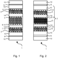
- FIG. 1 shows a fuel cell stack 1 with a plurality of fuel cells, which can be formed as unit cells.
- Each fuel cell 2 is formed from a membrane electrode arrangement 9 with an active region, to which a bipolar plate 14 is assigned on the anode side and a cathode side. Between the membrane electrode arrangement 9 and the bipolar plates 14, a cathode-side and an anode-side gas diffusion layer 10 is also arranged.
- the bipolar plate 14 is formed from two individual plates joined together, one of which provides a first media guide 6, i.e. a cathode flow field 11, and the other of which provides a second media guide 7, i.e. an anode flow field 12.
- a third media guide 8, namely a coolant flow field 13, is formed between them.
- the media guides 6, 7, 8 are each assigned or arranged in a compressible fabric structure 3, to which a spring function with a spring constant is assigned.
- the spring function enables a change in length of the fuel cell 2 along a stacking direction to be compensated by an opposite negative change in length of the compressible fabric structure 3.
- the spring function of the compressible fabric structure 3 enables a length compensation of the fuel cell 2 in all operating states, so that the fuel cells 2 in the stacking direction and thus the fuel cell stack 1 always have a defined length regardless of the operating state.
- FIG. 2 shows the fuel cell stack 1 in which the compressible fabric structures 3 are partially compressed.
- Thermal or hydrostatic expansion for example of the membrane electrode arrangement 9, leads to an increase in pressure between the terminal fuel cells 2 of the fuel cell stack 1.
- This increase in pressure is compensated by compression of the compressible fabric structure 3, so that within the fuel cell stack 1 between the two terminal fuel cells a specific contact force acts, which is constant across all operating modes of the fuel cell stack 1 and the length of the fuel cell stack also remains constant.
- the compressible fabric structures 3 can have different spring constants.
- the springing in the individual media guides 6, 7, 8 or flow fields 11, 12, 13 can thus be designed differently and thus adjusted.
- the fabric structures 3 of the first media guide 6 and the second media guide 7, i.e. the anode flow field 11 and the cathode flow field 12 have a higher spring constant than that of the third media guide 8, i.e. the coolant flow field 13. Consequently, the compressible fabric structure of the coolant flow field 13 is compressed the most, while the fabric structure 3 assigned to the anode flow field 12 and the cathode flow field 11 or arranged in it is only slightly compressible. As a result, the size of the anode spaces and the cathode spaces remains approximately constant, while the contact pressure and the fuel cell stack length are nevertheless constant.
- different fuel cells 2 within the fuel cell stack 1 can have compressible fabric structures 3 with different spring constants.
- the spring constants in the middle i.e. in the core of the fuel cell stack 1, can be selected differently than at the ends of the fuel cell stack 1.
- the compressible fabric structures 3 can also have a first region to which a first spring constant is assigned and a second region to which a second spring constant different from the first spring constant is assigned.
- the spring function of the compressible fabric structure 3 is formed by a regular arrangement of interwoven fibers 4.
- the spring function could also be provided by an irregular arrangement of interwoven fibers 4.
- FIG. 3 Another alternative of the compressible fabric structure 3 is in Figure 3 shown.
- the compressible fabric structure 3 has interwoven fibers 4 with a mean first amplitude.
- wave-shaped resilient fibers 5 with a mean second amplitude are present.
- the mean second amplitude is greater than the mean first amplitude, so that a spring function with a spring constant can be provided by the resilient fiber 5.
- Fig.4 shows a further embodiment of the compressible fabric structure 3, in which the spring function is provided by the fibers 4 themselves being formed in a wave-like manner, i.e. they are not interwoven with one another.
- the fibers 4,5 providing the spring function are at least partially made of a plastic or a metal.
Landscapes
- Life Sciences & Earth Sciences (AREA)
- Engineering & Computer Science (AREA)
- Manufacturing & Machinery (AREA)
- Sustainable Development (AREA)
- Sustainable Energy (AREA)
- Chemical & Material Sciences (AREA)
- Chemical Kinetics & Catalysis (AREA)
- Electrochemistry (AREA)
- General Chemical & Material Sciences (AREA)
- Fuel Cell (AREA)
Claims (10)
- Empilement de piles à combustible (1) avec une pluralité de piles à combustible (2) empilées les unes sur les autres le long d'une direction d'empilement, dans lequel au moins l'une des piles à combustible (2) présente au moins une structure de tissu compressible (3) à laquelle est associée une fonction de ressort avec une constante de ressort, dans lequel une variation de longueur de la pile à combustible (2) peut être compensée le long de la direction d'empilement au moyen de la fonction de ressort par une variation de longueur négative de la structure de tissu compressible (3), opposée à celle-ci, caractérisé en ce que la fonction de ressort de la structure de tissu compressible (3) permet une compensation de longueur des piles à combustible (2) dans tous les états de fonctionnement, de sorte que les piles à combustible (2) présentent une longueur définie dans une direction d'empilement, indépendamment de l'état de fonctionnement.
- Empilement de piles à combustible (1) selon la revendication 1, caractérisé en ce que chacune des piles à combustible (2) présente au moins une structure de tissu compressible (3) avec fonction de ressort associée.
- Empilement de piles à combustible (1) selon la revendication 1 ou 2, caractérisé en ce que la structure de tissu compressible (1) est formée à partir de fibres (4) entrelacées, et en ce que la fonction de ressort est formée par un agencement désordonné de fibres (4).
- Empilement de piles à combustible (1) selon la revendication 1 ou 2, caractérisé en ce que la structure de tissu compressible (3) est formée par des fibres (4) de forme ondulée qui fournissent la fonction de ressort.
- Empilement de piles à combustible (1) selon la revendication 1 ou 2, caractérisé en ce que la structure de tissu compressible (3) est formée à partir de fibres (4) entrelacées avec une première amplitude moyenne, et en ce qu'une fibre élastique (5) de forme ondulée est disponible pour la fourniture de la fonction de ressort, fibre qui est associée aux fibres (4) de la structure de tissu (3) ou est tissée avec celle-ci, et dont la seconde amplitude moyenne est supérieure à la première amplitude moyenne.
- Empilement de piles à combustible (1) selon l'une quelconque des revendications 3 à 5, caractérisé en ce que la fibre (4, 5) fournissant la fonction de ressort est formée au moins partiellement à partir d'une matière plastique ou à partir d'un métal.
- Empilement de piles à combustible (1) selon l'une quelconque des revendications 1 à 6, caractérisé en ce que la structure de tissu compressible (3) présente une première zone à laquelle est associée une première constante de ressort et présente une seconde zone à laquelle est associée une seconde constante de ressort différente de la première constante de ressort.
- Empilement de piles à combustible (1) selon l'une quelconque des revendications 1 à 7, caractérisé en ce que les piles à combustible (2) présentent respectivement une zone active, en ce qu'un premier guidage de fluide (6) est disponible pour le transport d'un premier réactif dans et/ou à partir de la zone active, un deuxième guidage de fluide (7) pour le transport d'un second réactif dans et/ou à partir de la zone active et un troisième guidage de fluide (8) pour le transport de liquide réfrigérant dans et/ou à partir de la zone active, et en ce que la structure de tissu compressible (3) est associée à au moins l'un des guidages de fluide (6, 7, 8) ou est disposée dans celui-ci.
- Empilement de piles à combustible (1) selon la revendication 8, caractérisé en ce qu'une pluralité de guidages de fluide (6, 7, 8) présente les structures de tissu compressibles (3), et en ce que différentes constantes de ressort sont associées aux structures de tissu compressibles (3) des différents guidages de fluide (6, 7, 8).
- Empilement de piles à combustible (1) selon la revendication 8 ou 9, caractérisé en ce que la structure de tissu compressible (3) est associée au troisième guidage de fluide (8) transportant le liquide de refroidissement et est disposée dans celui-ci.
Applications Claiming Priority (2)
| Application Number | Priority Date | Filing Date | Title |
|---|---|---|---|
| DE102021108981.6A DE102021108981A1 (de) | 2021-04-12 | 2021-04-12 | Brennstoffzellenstapel mit komprimierbarer Gewebestruktur |
| PCT/EP2022/059253 WO2022218813A1 (fr) | 2021-04-12 | 2022-04-07 | Empilement de piles à combustible à structure de tissu compressible |
Publications (2)
| Publication Number | Publication Date |
|---|---|
| EP4244923A1 EP4244923A1 (fr) | 2023-09-20 |
| EP4244923B1 true EP4244923B1 (fr) | 2024-07-31 |
Family
ID=81597956
Family Applications (1)
| Application Number | Title | Priority Date | Filing Date |
|---|---|---|---|
| EP22722413.6A Active EP4244923B1 (fr) | 2021-04-12 | 2022-04-07 | Empilement de piles à combustible à structure de tissu compressible |
Country Status (5)
| Country | Link |
|---|---|
| US (1) | US20240047727A1 (fr) |
| EP (1) | EP4244923B1 (fr) |
| CN (1) | CN116686122A (fr) |
| DE (1) | DE102021108981A1 (fr) |
| WO (1) | WO2022218813A1 (fr) |
Family Cites Families (11)
| Publication number | Priority date | Publication date | Assignee | Title |
|---|---|---|---|---|
| DE4340153C1 (de) | 1993-11-25 | 1995-03-09 | Solentec Ges Fuer Solare Und E | Vorrichtung zum Kontaktieren von Elektroden von Hochtemperatur-Brennstoffzellen |
| DE10042744A1 (de) | 2000-08-31 | 2002-03-28 | Omg Ag & Co Kg | PEM-Brennstoffzellenstapel |
| US6500319B2 (en) * | 2001-04-05 | 2002-12-31 | Giner Electrochemical Systems, Llc | Proton exchange membrane (PEM) electrochemical cell having an integral, electrically-conductive, compression pad |
| CN1309106C (zh) | 2002-03-26 | 2007-04-04 | 松下电器产业株式会社 | 电解质膜电极复合体、使用该复合体的燃料电池及其制造方法 |
| KR100760132B1 (ko) | 2005-02-28 | 2007-09-18 | 산요덴키가부시키가이샤 | 복합막, 복합막을 이용한 연료 전지 |
| DE102005022484B4 (de) | 2005-05-11 | 2016-02-18 | Carl Freudenberg Kg | Gasdiffusionsschicht und Anordnung umfassend zwei Gasdiffusionsschichten |
| JP5711927B2 (ja) * | 2010-09-30 | 2015-05-07 | マグネクス株式会社 | 固体酸化物型燃料電池 |
| JP6628224B2 (ja) * | 2015-12-07 | 2020-01-08 | パナソニックIpマネジメント株式会社 | 高温動作型燃料電池 |
| DE102016224696A1 (de) * | 2016-12-12 | 2018-06-14 | Robert Bosch Gmbh | Bipolarplatte für eine Brennstoffzelle und Brennstoffzelle |
| DE102018203827A1 (de) * | 2018-03-14 | 2019-09-19 | Robert Bosch Gmbh | Gasverteilerstruktur für eine Brennstoffzelle |
| DE102018205128A1 (de) * | 2018-04-05 | 2019-10-10 | Robert Bosch Gmbh | Verfahren zum Herstellen einer Brennstoffzelle sowie Brennstoffzelle |
-
2021
- 2021-04-12 DE DE102021108981.6A patent/DE102021108981A1/de active Pending
-
2022
- 2022-04-07 WO PCT/EP2022/059253 patent/WO2022218813A1/fr not_active Ceased
- 2022-04-07 US US18/257,280 patent/US20240047727A1/en active Pending
- 2022-04-07 EP EP22722413.6A patent/EP4244923B1/fr active Active
- 2022-04-07 CN CN202280008201.9A patent/CN116686122A/zh active Pending
Also Published As
| Publication number | Publication date |
|---|---|
| CN116686122A (zh) | 2023-09-01 |
| US20240047727A1 (en) | 2024-02-08 |
| WO2022218813A1 (fr) | 2022-10-20 |
| EP4244923A1 (fr) | 2023-09-20 |
| DE102021108981A1 (de) | 2022-10-13 |
Similar Documents
| Publication | Publication Date | Title |
|---|---|---|
| EP3884535B1 (fr) | Plaque de pile à combustible, plaque bipolaire et système de pile à combustible | |
| EP3679619B1 (fr) | Assemblage membrane-électrodes, empilement de cellules élémentaires ainsi que véhicule doté d'un tel empilement de cellules élémentaires | |
| EP3430662A1 (fr) | Plaque bipolaire à largeur variable des canaux à gaz de réaction dans la zone d'entrée de la zone active, empilement de cellules à combustible et système de cellules à combustible comportant de telles plaques bipolaires et véhicule | |
| WO2018108552A1 (fr) | Plaque bipolaire pour pile à combustible et pile à combustible | |
| DE102016121506A1 (de) | Bipolarplatte sowie Brennstoffzelle mit einer solchen | |
| EP3736894B1 (fr) | Plaque bipolaire pour piles à combustible, empilement de piles à combustible doté de telles plaques bipolaires ainsi que véhicule doté d'un tel empilement de piles à combustible | |
| DE112008002778T5 (de) | Brennstoffzelle | |
| DE102017215748A1 (de) | Kompressionsvorrichtung für einen Brennstoffzellenstapel | |
| DE102020128623A1 (de) | Brennstoffzellenstapel mit einem Kompressionssystem für den Brennstoffzellenstapel | |
| WO2010083788A1 (fr) | Unité de répétition pour un empilement de cellules électrochimiques | |
| EP3953986B1 (fr) | Plaque bipolaire pour piles à combustible, empilement de piles à combustible avec de telles plaques bipolaires ainsi que véhicule avec un tel empilement de piles à combustible | |
| DE102016120535A1 (de) | Brennstoffzelle, Brennstoffzellenstapel und Brennstoffzellensystem | |
| DE102018200842B4 (de) | Brennstoffzellenplatte, Bipolarplatten und Brennstoffzellenaufbau | |
| WO2022218813A1 (fr) | Empilement de piles à combustible à structure de tissu compressible | |
| DE102018211078B3 (de) | Bipolarplatte für Brennstoffzellen mit drei Einzelplatten, sowie Brennstoffzelle und Brennstoffzellenstapel mit solchen Bipolarplatten | |
| EP4073859A1 (fr) | Kit pour empilement de piles à combustible et procédé de fabrication d'empilement de piles à combustible | |
| DE102019206117A1 (de) | Brennstoffzellenstapel umfassend variable Biopolarplatten | |
| WO2022089898A1 (fr) | Plaque de distribution pour cellule électrochimique et cellule électrochimique | |
| DE102019203321A1 (de) | Brennstoffzellenplatte, Brennstoffzellenaufbau und Brennstoffzellensystem | |
| DE102018210165A1 (de) | Spannsystem für Brennstoffzellenstapel und Brennstoffzellenstapel mit einem solchen | |
| DE102019206118A1 (de) | Bipolarplatte für Brennstoffzellen umfassend elastische elektrodenseitige Strukturelemente | |
| DE102017215486B4 (de) | Elektrischer Verbinder sowie Brennstoffzellenstapel mit einem solchen | |
| DE102019205579A1 (de) | Bipolarplatte für Brennstoffzellen, Brennstoffzellenstapel mit solchen Bipolarplatten sowie Fahrzeug mit einem solchen Brennstoffzellenstapel | |
| DE102015200804B4 (de) | Membran-Elektroden-Einheit und Verfahren zur Herstellung | |
| DE102020127464A1 (de) | Bipolarplatte mit orthogonalen Kühlmittelkanälen, Brennstoffzellenaufbau und Brennstoffzellenstapel |
Legal Events
| Date | Code | Title | Description |
|---|---|---|---|
| STAA | Information on the status of an ep patent application or granted ep patent |
Free format text: STATUS: UNKNOWN |
|
| STAA | Information on the status of an ep patent application or granted ep patent |
Free format text: STATUS: THE INTERNATIONAL PUBLICATION HAS BEEN MADE |
|
| PUAI | Public reference made under article 153(3) epc to a published international application that has entered the european phase |
Free format text: ORIGINAL CODE: 0009012 |
|
| STAA | Information on the status of an ep patent application or granted ep patent |
Free format text: STATUS: REQUEST FOR EXAMINATION WAS MADE |
|
| 17P | Request for examination filed |
Effective date: 20230612 |
|
| AK | Designated contracting states |
Kind code of ref document: A1 Designated state(s): AL AT BE BG CH CY CZ DE DK EE ES FI FR GB GR HR HU IE IS IT LI LT LU LV MC MK MT NL NO PL PT RO RS SE SI SK SM TR |
|
| GRAP | Despatch of communication of intention to grant a patent |
Free format text: ORIGINAL CODE: EPIDOSNIGR1 |
|
| STAA | Information on the status of an ep patent application or granted ep patent |
Free format text: STATUS: GRANT OF PATENT IS INTENDED |
|
| DAV | Request for validation of the european patent (deleted) | ||
| DAX | Request for extension of the european patent (deleted) | ||
| INTG | Intention to grant announced |
Effective date: 20240326 |
|
| GRAS | Grant fee paid |
Free format text: ORIGINAL CODE: EPIDOSNIGR3 |
|
| GRAA | (expected) grant |
Free format text: ORIGINAL CODE: 0009210 |
|
| STAA | Information on the status of an ep patent application or granted ep patent |
Free format text: STATUS: THE PATENT HAS BEEN GRANTED |
|
| AK | Designated contracting states |
Kind code of ref document: B1 Designated state(s): AL AT BE BG CH CY CZ DE DK EE ES FI FR GB GR HR HU IE IS IT LI LT LU LV MC MK MT NL NO PL PT RO RS SE SI SK SM TR |
|
| REG | Reference to a national code |
Ref country code: CH Ref legal event code: EP Ref country code: GB Ref legal event code: FG4D Free format text: NOT ENGLISH |
|
| REG | Reference to a national code |
Ref country code: DE Ref legal event code: R096 Ref document number: 502022001367 Country of ref document: DE |
|
| REG | Reference to a national code |
Ref country code: IE Ref legal event code: FG4D Free format text: LANGUAGE OF EP DOCUMENT: GERMAN |
|
| P01 | Opt-out of the competence of the unified patent court (upc) registered |
Free format text: CASE NUMBER: APP_46881/2024 Effective date: 20240813 |
|
| REG | Reference to a national code |
Ref country code: LT Ref legal event code: MG9D |
|
| REG | Reference to a national code |
Ref country code: NL Ref legal event code: MP Effective date: 20240731 |
|
| PG25 | Lapsed in a contracting state [announced via postgrant information from national office to epo] |
Ref country code: PT Free format text: LAPSE BECAUSE OF FAILURE TO SUBMIT A TRANSLATION OF THE DESCRIPTION OR TO PAY THE FEE WITHIN THE PRESCRIBED TIME-LIMIT Effective date: 20241202 |
|
| PG25 | Lapsed in a contracting state [announced via postgrant information from national office to epo] |
Ref country code: PT Free format text: LAPSE BECAUSE OF FAILURE TO SUBMIT A TRANSLATION OF THE DESCRIPTION OR TO PAY THE FEE WITHIN THE PRESCRIBED TIME-LIMIT Effective date: 20241202 |
|
| PG25 | Lapsed in a contracting state [announced via postgrant information from national office to epo] |
Ref country code: NO Free format text: LAPSE BECAUSE OF FAILURE TO SUBMIT A TRANSLATION OF THE DESCRIPTION OR TO PAY THE FEE WITHIN THE PRESCRIBED TIME-LIMIT Effective date: 20241031 |
|
| PG25 | Lapsed in a contracting state [announced via postgrant information from national office to epo] |
Ref country code: FI Free format text: LAPSE BECAUSE OF FAILURE TO SUBMIT A TRANSLATION OF THE DESCRIPTION OR TO PAY THE FEE WITHIN THE PRESCRIBED TIME-LIMIT Effective date: 20240731 Ref country code: PL Free format text: LAPSE BECAUSE OF FAILURE TO SUBMIT A TRANSLATION OF THE DESCRIPTION OR TO PAY THE FEE WITHIN THE PRESCRIBED TIME-LIMIT Effective date: 20240731 Ref country code: GR Free format text: LAPSE BECAUSE OF FAILURE TO SUBMIT A TRANSLATION OF THE DESCRIPTION OR TO PAY THE FEE WITHIN THE PRESCRIBED TIME-LIMIT Effective date: 20241101 Ref country code: NL Free format text: LAPSE BECAUSE OF FAILURE TO SUBMIT A TRANSLATION OF THE DESCRIPTION OR TO PAY THE FEE WITHIN THE PRESCRIBED TIME-LIMIT Effective date: 20240731 |
|
| PG25 | Lapsed in a contracting state [announced via postgrant information from national office to epo] |
Ref country code: BG Free format text: LAPSE BECAUSE OF FAILURE TO SUBMIT A TRANSLATION OF THE DESCRIPTION OR TO PAY THE FEE WITHIN THE PRESCRIBED TIME-LIMIT Effective date: 20240731 |
|
| PG25 | Lapsed in a contracting state [announced via postgrant information from national office to epo] |
Ref country code: LV Free format text: LAPSE BECAUSE OF FAILURE TO SUBMIT A TRANSLATION OF THE DESCRIPTION OR TO PAY THE FEE WITHIN THE PRESCRIBED TIME-LIMIT Effective date: 20240731 |
|
| PG25 | Lapsed in a contracting state [announced via postgrant information from national office to epo] |
Ref country code: IS Free format text: LAPSE BECAUSE OF FAILURE TO SUBMIT A TRANSLATION OF THE DESCRIPTION OR TO PAY THE FEE WITHIN THE PRESCRIBED TIME-LIMIT Effective date: 20241130 |
|
| PG25 | Lapsed in a contracting state [announced via postgrant information from national office to epo] |
Ref country code: HR Free format text: LAPSE BECAUSE OF FAILURE TO SUBMIT A TRANSLATION OF THE DESCRIPTION OR TO PAY THE FEE WITHIN THE PRESCRIBED TIME-LIMIT Effective date: 20240731 |
|
| PG25 | Lapsed in a contracting state [announced via postgrant information from national office to epo] |
Ref country code: RS Free format text: LAPSE BECAUSE OF FAILURE TO SUBMIT A TRANSLATION OF THE DESCRIPTION OR TO PAY THE FEE WITHIN THE PRESCRIBED TIME-LIMIT Effective date: 20241031 Ref country code: ES Free format text: LAPSE BECAUSE OF FAILURE TO SUBMIT A TRANSLATION OF THE DESCRIPTION OR TO PAY THE FEE WITHIN THE PRESCRIBED TIME-LIMIT Effective date: 20240731 |
|
| PG25 | Lapsed in a contracting state [announced via postgrant information from national office to epo] |
Ref country code: RS Free format text: LAPSE BECAUSE OF FAILURE TO SUBMIT A TRANSLATION OF THE DESCRIPTION OR TO PAY THE FEE WITHIN THE PRESCRIBED TIME-LIMIT Effective date: 20241031 Ref country code: PL Free format text: LAPSE BECAUSE OF FAILURE TO SUBMIT A TRANSLATION OF THE DESCRIPTION OR TO PAY THE FEE WITHIN THE PRESCRIBED TIME-LIMIT Effective date: 20240731 Ref country code: NO Free format text: LAPSE BECAUSE OF FAILURE TO SUBMIT A TRANSLATION OF THE DESCRIPTION OR TO PAY THE FEE WITHIN THE PRESCRIBED TIME-LIMIT Effective date: 20241031 Ref country code: NL Free format text: LAPSE BECAUSE OF FAILURE TO SUBMIT A TRANSLATION OF THE DESCRIPTION OR TO PAY THE FEE WITHIN THE PRESCRIBED TIME-LIMIT Effective date: 20240731 Ref country code: LV Free format text: LAPSE BECAUSE OF FAILURE TO SUBMIT A TRANSLATION OF THE DESCRIPTION OR TO PAY THE FEE WITHIN THE PRESCRIBED TIME-LIMIT Effective date: 20240731 Ref country code: IS Free format text: LAPSE BECAUSE OF FAILURE TO SUBMIT A TRANSLATION OF THE DESCRIPTION OR TO PAY THE FEE WITHIN THE PRESCRIBED TIME-LIMIT Effective date: 20241130 Ref country code: HR Free format text: LAPSE BECAUSE OF FAILURE TO SUBMIT A TRANSLATION OF THE DESCRIPTION OR TO PAY THE FEE WITHIN THE PRESCRIBED TIME-LIMIT Effective date: 20240731 Ref country code: GR Free format text: LAPSE BECAUSE OF FAILURE TO SUBMIT A TRANSLATION OF THE DESCRIPTION OR TO PAY THE FEE WITHIN THE PRESCRIBED TIME-LIMIT Effective date: 20241101 Ref country code: FI Free format text: LAPSE BECAUSE OF FAILURE TO SUBMIT A TRANSLATION OF THE DESCRIPTION OR TO PAY THE FEE WITHIN THE PRESCRIBED TIME-LIMIT Effective date: 20240731 Ref country code: ES Free format text: LAPSE BECAUSE OF FAILURE TO SUBMIT A TRANSLATION OF THE DESCRIPTION OR TO PAY THE FEE WITHIN THE PRESCRIBED TIME-LIMIT Effective date: 20240731 Ref country code: BG Free format text: LAPSE BECAUSE OF FAILURE TO SUBMIT A TRANSLATION OF THE DESCRIPTION OR TO PAY THE FEE WITHIN THE PRESCRIBED TIME-LIMIT Effective date: 20240731 |
|
| PG25 | Lapsed in a contracting state [announced via postgrant information from national office to epo] |
Ref country code: RO Free format text: LAPSE BECAUSE OF FAILURE TO SUBMIT A TRANSLATION OF THE DESCRIPTION OR TO PAY THE FEE WITHIN THE PRESCRIBED TIME-LIMIT Effective date: 20240731 Ref country code: SM Free format text: LAPSE BECAUSE OF FAILURE TO SUBMIT A TRANSLATION OF THE DESCRIPTION OR TO PAY THE FEE WITHIN THE PRESCRIBED TIME-LIMIT Effective date: 20240731 Ref country code: DK Free format text: LAPSE BECAUSE OF FAILURE TO SUBMIT A TRANSLATION OF THE DESCRIPTION OR TO PAY THE FEE WITHIN THE PRESCRIBED TIME-LIMIT Effective date: 20240731 |
|
| PG25 | Lapsed in a contracting state [announced via postgrant information from national office to epo] |
Ref country code: EE Free format text: LAPSE BECAUSE OF FAILURE TO SUBMIT A TRANSLATION OF THE DESCRIPTION OR TO PAY THE FEE WITHIN THE PRESCRIBED TIME-LIMIT Effective date: 20240731 |
|
| PG25 | Lapsed in a contracting state [announced via postgrant information from national office to epo] |
Ref country code: CZ Free format text: LAPSE BECAUSE OF FAILURE TO SUBMIT A TRANSLATION OF THE DESCRIPTION OR TO PAY THE FEE WITHIN THE PRESCRIBED TIME-LIMIT Effective date: 20240731 |
|
| PG25 | Lapsed in a contracting state [announced via postgrant information from national office to epo] |
Ref country code: IT Free format text: LAPSE BECAUSE OF FAILURE TO SUBMIT A TRANSLATION OF THE DESCRIPTION OR TO PAY THE FEE WITHIN THE PRESCRIBED TIME-LIMIT Effective date: 20240731 Ref country code: SK Free format text: LAPSE BECAUSE OF FAILURE TO SUBMIT A TRANSLATION OF THE DESCRIPTION OR TO PAY THE FEE WITHIN THE PRESCRIBED TIME-LIMIT Effective date: 20240731 |
|
| REG | Reference to a national code |
Ref country code: DE Ref legal event code: R097 Ref document number: 502022001367 Country of ref document: DE |
|
| PLBE | No opposition filed within time limit |
Free format text: ORIGINAL CODE: 0009261 |
|
| STAA | Information on the status of an ep patent application or granted ep patent |
Free format text: STATUS: NO OPPOSITION FILED WITHIN TIME LIMIT |
|
| 26N | No opposition filed |
Effective date: 20250501 |
|
| PGFP | Annual fee paid to national office [announced via postgrant information from national office to epo] |
Ref country code: DE Payment date: 20250430 Year of fee payment: 4 |
|
| PGFP | Annual fee paid to national office [announced via postgrant information from national office to epo] |
Ref country code: FR Payment date: 20250426 Year of fee payment: 4 |
|
| PGFP | Annual fee paid to national office [announced via postgrant information from national office to epo] |
Ref country code: AT Payment date: 20250721 Year of fee payment: 4 |
|
| PG25 | Lapsed in a contracting state [announced via postgrant information from national office to epo] |
Ref country code: SE Free format text: LAPSE BECAUSE OF FAILURE TO SUBMIT A TRANSLATION OF THE DESCRIPTION OR TO PAY THE FEE WITHIN THE PRESCRIBED TIME-LIMIT Effective date: 20240731 |
|
| REG | Reference to a national code |
Ref country code: CH Ref legal event code: H13 Free format text: ST27 STATUS EVENT CODE: U-0-0-H10-H13 (AS PROVIDED BY THE NATIONAL OFFICE) Effective date: 20251125 |
|
| PG25 | Lapsed in a contracting state [announced via postgrant information from national office to epo] |
Ref country code: LU Free format text: LAPSE BECAUSE OF NON-PAYMENT OF DUE FEES Effective date: 20250407 |
|
| PG25 | Lapsed in a contracting state [announced via postgrant information from national office to epo] |
Ref country code: MC Free format text: LAPSE BECAUSE OF FAILURE TO SUBMIT A TRANSLATION OF THE DESCRIPTION OR TO PAY THE FEE WITHIN THE PRESCRIBED TIME-LIMIT Effective date: 20240731 |
|
| REG | Reference to a national code |
Ref country code: BE Ref legal event code: MM Effective date: 20250430 |
|
| PG25 | Lapsed in a contracting state [announced via postgrant information from national office to epo] |
Ref country code: BE Free format text: LAPSE BECAUSE OF NON-PAYMENT OF DUE FEES Effective date: 20250430 |
|
| PG25 | Lapsed in a contracting state [announced via postgrant information from national office to epo] |
Ref country code: CH Free format text: LAPSE BECAUSE OF NON-PAYMENT OF DUE FEES Effective date: 20250430 |
|
| PGFP | Annual fee paid to national office [announced via postgrant information from national office to epo] |
Ref country code: GB Payment date: 20260324 Year of fee payment: 5 |
|
| PG25 | Lapsed in a contracting state [announced via postgrant information from national office to epo] |
Ref country code: IE Free format text: LAPSE BECAUSE OF NON-PAYMENT OF DUE FEES Effective date: 20250407 |