EP3140475B1 - Support - Google Patents
Support Download PDFInfo
- Publication number
- EP3140475B1 EP3140475B1 EP15734662.8A EP15734662A EP3140475B1 EP 3140475 B1 EP3140475 B1 EP 3140475B1 EP 15734662 A EP15734662 A EP 15734662A EP 3140475 B1 EP3140475 B1 EP 3140475B1
- Authority
- EP
- European Patent Office
- Prior art keywords
- base
- per
- exhibits
- area
- ballast
- Prior art date
- Legal status (The legal status is an assumption and is not a legal conclusion. Google has not performed a legal analysis and makes no representation as to the accuracy of the status listed.)
- Active
Links
Images












Classifications
-
- E—FIXED CONSTRUCTIONS
- E04—BUILDING
- E04H—BUILDINGS OR LIKE STRUCTURES FOR PARTICULAR PURPOSES; SWIMMING OR SPLASH BATHS OR POOLS; MASTS; FENCING; TENTS OR CANOPIES, IN GENERAL
- E04H12/00—Towers; Masts or poles; Chimney stacks; Water-towers; Methods of erecting such structures
- E04H12/22—Sockets or holders for poles or posts
- E04H12/2238—Sockets or holders for poles or posts to be placed on the ground
- E04H12/2246—Sockets or holders for poles or posts to be placed on the ground filled with water, sand or the like
-
- A—HUMAN NECESSITIES
- A47—FURNITURE; DOMESTIC ARTICLES OR APPLIANCES; COFFEE MILLS; SPICE MILLS; SUCTION CLEANERS IN GENERAL
- A47G—HOUSEHOLD OR TABLE EQUIPMENT
- A47G33/00—Religious or ritual equipment in dwelling or for general use
- A47G33/04—Christmas trees
- A47G33/12—Christmas tree stands
-
- E—FIXED CONSTRUCTIONS
- E04—BUILDING
- E04H—BUILDINGS OR LIKE STRUCTURES FOR PARTICULAR PURPOSES; SWIMMING OR SPLASH BATHS OR POOLS; MASTS; FENCING; TENTS OR CANOPIES, IN GENERAL
- E04H12/00—Towers; Masts or poles; Chimney stacks; Water-towers; Methods of erecting such structures
- E04H12/22—Sockets or holders for poles or posts
- E04H12/2253—Mounting poles or posts to the holder
- E04H12/2269—Mounting poles or posts to the holder in a socket
-
- F—MECHANICAL ENGINEERING; LIGHTING; HEATING; WEAPONS; BLASTING
- F16—ENGINEERING ELEMENTS AND UNITS; GENERAL MEASURES FOR PRODUCING AND MAINTAINING EFFECTIVE FUNCTIONING OF MACHINES OR INSTALLATIONS; THERMAL INSULATION IN GENERAL
- F16M—FRAMES, CASINGS OR BEDS OF ENGINES, MACHINES OR APPARATUS, NOT SPECIFIC TO ENGINES, MACHINES OR APPARATUS PROVIDED FOR ELSEWHERE; STANDS; SUPPORTS
- F16M2200/00—Details of stands or supports
- F16M2200/08—Foot or support base
Definitions
- the invention relates to a base with a holding device for holding an object to be placed, with a receiving area for receiving a removable ballast weight in a receiving position.
- a ballast weight that can be used with the stand serves to stabilize the base and increases its overturning moment. With tilting moment is meant the torque that must be applied to tip over the base with the object to be erected.
- EP 0822 305 discloses such a generic base.
- the receiving position for the ballast weight is arranged radially outboard and radially inwardly of the receiving position is arranged in the circumferential direction at least partially a raised area.
- the raised area serves as a means for specifying the receiving position of the removable ballast weight.
- the raised area which may be formed, for example, in the form of a circumferential bead, the ballast weight used with the base is secured in the receiving position against slipping.
- the raised area can also be formed by a stop surface or in a preferred embodiment by an inclined surface.
- the raised area comprises a transport surface, which preferably adjoins the receiving area.
- a transport surface is to be understood as an area or surface via which a ballast weight to be received in the receiving area can be transported. This allows the loading of the base with a ballast weight, without the ballast weight would have to be used directly in the receiving position.
- the ballast weight can be applied to the transport surface at a suitable location on the base and then passes via the transport surface into the receiving position in the receiving region.
- the transport surface has substantially the shape of a lateral surface of a truncated cone. This represents an easy to manufacture and reliable and effective-acting embodiment of the transport surface.
- the base comprises a feed area, in which the Ballast weight is inserted, and which is designed such that the ballast weight after insertion moves gravity driven over the transport surface in the receiving position, preferably moves rolling and / or sliding in the receiving position.
- This makes it possible to easily and easily introduce the ballast weight in the receiving area over the feed area. From the feed area, the ballast weight then moves due to its weight over the transport surface in the receiving position in the receiving area.
- an insertion device is arranged between the holding device and the feed region, which has an insertion surface which essentially has the shape of a lateral surface of a truncated cone and with respect to the stand side in total at an angle between 7 ° and 35 °, preferably between 12 ° and 25 °, in particular between 15 ° and 20 °, is inclined.
- the ballast weight can be particularly easily and conveniently inserted into the base. The ballast weight then reaches the intended receiving position in the receiving area via the feed area and the transport area.
- the base comprises an upper element and a lower element which are detachably or non-detachably connected to one another, and the upper element delimits the receiving area in the direction of an upper side and the lower element delimits the receiving area in the direction of a stand side.
- the described two-part construction allows a cost-effective production of the stand according to the invention.
- the stand according to the invention can be assembled easily by this structure.
- the limitation of the receiving area by the upper or the lower element has the advantage that a ballast weight received in the receiving position is largely protected from the effects of weather, since the receiving position is largely surrounded by the upper and lower elements. This allows, for example, the use of less weather-resistant materials for the production of ballast weight.
- the base is essentially rotationally symmetrical, preferably rotationally symmetrical with respect to the holding device.
- a holding insert is formed by an adapter element (or adapter device), in particular a hollow-cylindrical adapter element, which is designed to hold the object to be erected.
- the object to be erected can thus be inserted into the adapter element (or into the adapter device) and the adapter element can be inserted into the holding device.
- the base according to the invention is characterized in that at least one nub is arranged on the side of the stand, wherein the nub preferably has a cylindrical recess for receiving a leveling element.
- a leveling element is to be understood an element which can be fastened in at least two different recessed positions in the nub.
- the leveling element may for example be formed pin-shaped and are introduced variably deep into the knob. As a result, unevenness in the surface on which the stand is, be compensated.
- the base has a plurality of nubs, which are arranged distributed on the stand side, in particular a plurality of knobs with leveling elements.
- the support element is annular and arranged in a recess formed on the stand side of the base.
- a plurality of support elements are arranged in the form of cylindrical pins on the underside of the base.
- the support element or the support elements is produced using a polymeric material.
- Another advantage is when the support element or the support elements on their stand-side surfaces, that is, on the surfaces which face the substrate on which the pedestal stands, have a lubricity-promoting coating, preferably a ceramic-based coating, which is advantageously vapor-deposited.
- the material of the support element or the support elements is advantageously chosen so that the support element or the support elements are compressed when a ballast weight is in the receiving position, wherein the support element or the support elements in the compressed state flush with the stand-side outline of the base runs or runs.
- the weight of the ballast weight compresses the support element or the support elements such that the base is seated on, for example, the knobs arranged on the side of the stand.
- a projecting area is arranged on the stand side and a recessed area is arranged on the upper side which is so complementary to the projecting area that a protruding area of a substantially identical second pedestal is recessed into the recessed area Area usable, preferably form-fitting and / or non-positively used.
- a protruding area of a substantially identical second pedestal is recessed into the recessed area Area usable, preferably form-fitting and / or non-positively used.
- An advantageous development of the base according to the invention is characterized in that in the region of the recessed area a support surface is formed, which is in contact with a protruding region of the substantially identical second base, which is inserted into the base, and is designed to forces, which act due to the weight of the substantially identical second base to guide on a stand side of the stand, wherein the support surface preferably by an upper side of the Adapter element is formed.
- ballast weight for weighting one of the above feet, which is characterized in that it is a plurality of flexibly interconnected or connectable individual weights or ballast elements, preferably a plurality of substantially spherical, cylindrical or barrel-shaped, comprises flexibly interconnected ballast elements.
- the ballast elements of the just described embodiment of the ballast weight thus form a kind of chain, whereby the ballast weight is easy to transport and can be introduced into the receiving position in an advantageous manner.
- the described shape of the ballast weight allows, when used with the above-described base, a simple introduction of the ballast weight by means of the insertion device into the feed area, as well as a simple transport of the ballast weight over the transport surface of the base.
- ballast weight represents a preferred implementation of a chain-type version of the ballast weight, which is advantageous in terms of handling and applicability of the ballast weight.
- ballast weight which comprises a metallic material, preferably comprises a plurality of flexibly interconnected ballast elements, wherein at least one ballast element, preferably all ballast elements comprises or comprise a metallic material, preferably consists of at least one metallic material or consist.
- Metallic materials have a particularly high density and thus allow for a small footprint high stabilization of the base by the ballast weight used.
- the combination of the base according to the invention with the matching ballast weight stable erection of an object to be erected is achieved. Due to the external arrangement of the ballast weight in the receiving position of the base receives a high tilt stability.
- the ballast weight can be removed from the receiving position and the base and the ballast weight can be transported separately from each other. This also allows people to transport the base in a simple and comfortable way that would not physically be able to wear the base and the ballast weight simultaneously.
- a ballast weight as described above wherein the ballast weight is arranged in the receiving position such that when looking at a stand side at least 80%, preferably 90%, in particular 100%, the mass of the ballast weight outside an inner Circle, and that a circle center of the inner circle is a geometric center of the holder, and a diameter of the inner circle is at least 50%, preferably 60%, especially 65%, of a diameter of an outer circle, and the outer circle is the smallest possible circle , which completely surrounds the base when looking at the stand side. Due to the arrangement of the receiving position just described a high stability of the base is achieved. This results from the high tilting moment, which can be absorbed by the stand due to the ballast weight arranged in an advantageous manner. Since the complete ballast weight is far away from the holding device, the stabilizing weight of the ballast weight is used efficiently. This can be used with high tilt stability a ballast weight with low weight.
- the pedestal is made using a polymeric material, preferably a polymeric material. This allows a cost-effective production by injection molding.
- the connection can be detachable or non-detachable.
- the receiving area is then designed, for example, watertight, so that the base can be filled with a fixed ballast weight but also with a flowable ballast, preferably water and / or sand.
- the stand comprises at least one primary support element which has an elastically deformable first part body and at least one second part body comprising a ceramic material, which is arranged on the first part body.
- the base comprises at least one secondary support element, wherein, in particular in an unloaded state, the primary support element further extends from a base plane of the base out than the secondary support element.
- the primary support element is arranged on a base body, for example a housing, of the base.
- the first part of the body facing the body (so to speak, "up")
- the second body part faces a support surface (so to speak, "down”).
- the elastically deformable first partial body can press the second partial body against the carrier surface (resiliently).
- the first part of the body is so comparatively soft, resilient, yielding, executed
- the second part of the body is so comparatively hard, solid, rigid, smooth, executed.
- the base comprises a plurality of primary support elements, for example five pieces. Due to the elasticity of the first part of the body can press the individual primary support elements substantially independently of each other against the support surface. As a result, an entire bearing force of the pedestal can advantageously be distributed relatively uniformly over the individual primary support elements, and thus also any unevenness of the support surface can be compensated for. Due to the described differentiated properties of the first and the second partial body, the base can be particularly expedient and comparatively robust and durable.
- the support tube is held by means of at least one at least approximately designed as a hollow cylinder adapter device on the base.
- a support tube with a different diameter can be arranged on the base.
- the support tube is positively held on the base, wherein the support tube and / or the at least one adapter device is held by means of at least one screw on the base.
- the support tube can be particularly easily mounted or removed.
- the base has a standing surface provided for arrangement on a carrier surface and a receiving surface substantially opposite the base surface, wherein a receiving device having at least one groove for receiving a hollow cylinder is arranged in the area of the receiving surface.
- a receiving device having at least one groove for receiving a hollow cylinder is arranged in the area of the receiving surface.
- the hollow cylinder is designed as a bendable and / or bendable plate.
- the holding device comprises at least one adapter device for holding the object to be erected, wherein the adapter device has at least one radially acting clamping device, and wherein a radial dimension of the clamping device is substantially infinitely adjustable.
- the clamping device comprises at least a first clamping element, which is in particular substantially rigidly coupled to the base, wherein the clamping device comprises at least a second clamping element, which can be arranged radially between the first clamping element and the object to be erected the first clamping element has a first contact surface and the second clamping element has a second contact surface, wherein the first and second contact surfaces at least partially contact, wherein in particular a contact surface has an area of at least about 20 square millimeters.
- the clamping device can be produced particularly inexpensively and is also particularly variable usable.
- the first and / or the second contact surface is formed at least in sections, preferably predominantly flat.
- the first and / or the second contact surface is designed to be more than 90% of a total surface.
- the first and / or the second contact surface is formed substantially rectangular, wherein a width of the first and the second contact surface is smaller than a length of the first and the second contact surface, and wherein a longitudinal axis of the first or the second contact surface
- the second contact surface forms an angle between about 2 ° and about 45 °, in particular between about 5 ° and about 30 °, with a longitudinal axis of the base. These angles characterize a particularly suitable clamping device.
- At least one surface of at least one clamping element preferably a surface of the second clamping element, in particular a surface opposite the first or the second contact surface, at least in sections has a geometry of a clothoid.
- a holding insert is arranged in the holding device of the base.
- the holding insert is designed as a hollow cylindrical adapter element.
- the object to be erected is arranged non-positively in the inner cavity or can be arranged.
- the holding insert on a bearing surface.
- the holding insert is designed as a cylindrical sleeve which is formed with an opening to the top of the respective stand substantially cylindrical receiving space.
- the sleeve has at least one threaded bolt which can be screwed into the receiving space.
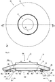
- An inventive stand 10, shown in FIG. 1 comprises a holding device 12 for receiving an object 250 to be set up (see FIG. 20 ).
- a holding device 12 for receiving an object 250 to be set up (see FIG. 20 ).
- top view is mainly an upper element 14 visible.
- a sub-element 16 is visible only in the region of the holding device 12.
- FIG. 2 A sectional view of the stand 10 along the line II-II is in FIG. 2 shown.
- a receiving position 24 of a ballast weight 60 not shown here (see, for example, the FIG. 5 ) is schematically represented by a broken line. If the ballast weight 60 is received in the receiving area 20, then it is in the receiving position 24. As viewed from the receiving position 24, a direction pointing radially inward is indicated by arrows 26. From the receiving position 24 radially inwardly a raised portion 28 is arranged.
- the raised region 28 comprises a transport surface 32, which adjoins the receiving region 20.
- the transport surface 32 has substantially the shape of a lateral surface of a truncated cone.
- the Transport surface 32 is inclined at an angle 36 of about 17 ° relative to a stand side 40 of the base 10.
- the transport surface 32 relative to the stand side 40 in total at an angle 36 between 5 ° and 30 °, preferably between 10 ° and 22 °, in particular between 12 ° and 18 °, be inclined.
- the upper element 14 and the lower element 16 are detachably or non-detachably connected to one another, the upper element 14 delimiting the receiving region 20 in the direction of an upper side 84 and the lower element 16 delimiting the receiving region 20 in the direction of a stand side 40.
- the support element 110 is designed particularly differentiated and is referred to there as the primary support element 252. See also the Figures 20 and 21 ,
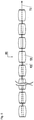
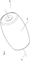
- the ballast weight 60 has a through hole 76 along an imaginary longitudinal axis 74.
- the through hole 76 serves to receive the connecting means 68, so that a plurality of ballast elements 64 can be threaded onto the connecting means 68, as it were, in order to form a ballast weight 60.
- the connecting means 68 preferably has local circumferential extensions which space the ballast elements 64 from one another.
- ballast elements 64 of the ballast weight 60 in FIG. 5 and thus also the ballast element 64 in FIG. 6 consist of a metallic material.
- the ballast weight 60 comprises a metallic material
- the ballast weight 60 comprises a plurality of flexibly connected ballast elements 64 and at least one ballast element 64, preferably all ballast elements 64, a metallic material include or include.
- FIG. 7 shows the base 10 from the FIGS. 1 to 4 and an identical base 10b, which is connected to the base 10.
- the elements of the base 10 corresponding elements of the base 10b bear corresponding reference numerals with the index b.
- the connection between the base 10 and the identically formed base 10b is realized via a protruding region 80b formed on the side 40b and a recessed region 88 formed on an upper side 84 opposite the side 40.
- the recessed areas 88, 88b are complementary to the protruding areas 80, 80b.
- Complementary means that the protruding region 80, 80b of one base 10 or 10b can be inserted into the recessed region 88, 88b of the other base 10b or 10, preferably in a form-fitting and / or force-fit manner.
- FIG. 8 shows the base 10 with the ballast weight 60, wherein the ballast weight 60 is received in the receiving position 24 in the receiving area 20. The ballast weight 60 is held over the raised portion 28 in the receiving position 24.
- the ballast weight 60 can be introduced into the feed region 44 by means of an insertion device 90.
- the insertion device 90 has an insertion surface 94, on which the ballast weight 60 can be placed. Following placement on the insertion surface 94, the ballast weight 60 moves gravity-driven over the transport surface 32 and thereby into the receiving position 24. Due to gravity, the ballast weight 60 so to speak rolls with its barrel-shaped ballast elements 64 via the insertion surface 94 and the transport surface 32 in the Pickup position 24.
- the insertion surface has substantially the shape of a lateral surface of a truncated cone and is compared with the stand side 40 at an angle of between 7 ° and 35 °, preferably between 12 ° and 25 °, in particular between 15 ° and 20 °, inclined.
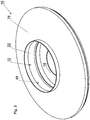
- FIG. 9 shows a representation of the base 10 accordingly FIG. 1 , In FIG. 9 In addition, a geometric center 100 of the holding device 12 is shown.
- An outer circle 102 is the smallest possible circle, which completely surrounds the base 10 when looking at the stand side 40. Due to the rotationally symmetrical design of the base 10, the outer circle 102 coincides in the present example with the outer contour of the base 10. In differently shaped embodiments of the stand 10 according to the invention, however, this is not necessarily the case.
- a first inner circle 104 has a diameter which corresponds to 50% of the diameter of the outer circle.
- a second inner circle 106 has a diameter which corresponds to 60% of the diameter of the outer circle 102 and a third inner circle 108 has a diameter which corresponds to 65% of the diameter of the outer circle 102.
- the receiving position 24 for a ballast weight 60 is such that the complete ballast weight 60, and thus in the present embodiment also 100% of its mass, outside of the three inner circles 104, 106 and 108.
- the center of the inner circles 104, 106 and 108 corresponds to the center 100 of the holding device 12.
- the ballast weight 60 is arranged in the receiving position 24 such that when looking at a stand side 40 at least 80%, preferably 90%, in particular 100%, the mass of the ballast weight 60 outside an inner circle 104, 106, 108 are located, and that a circle center of the inner circle 104, 106, 108 is a geometric center 100 of the holding device 12, and that a diameter of the inner circle 104, 106, 108 at least 50%, preferably 60%, in particular 65%, of a diameter of an outer circle 102nd is, and that the outer circle is the smallest possible circle 102, which completely surrounds the base 10 when looking at the stand side 40.
- FIG. 10 shows a base 10 and an identical base 10b, which is connected to the base 10.
- the holding inserts 118, 118b are in FIG. 10 designed as a hollow cylindrical adapter elements 120, 120b.
- the holding inserts 118, 118b can each be inserted or inserted an object to be placed 250. This insertion is preferably non-positively.
- the object to be placed 250 can thereby be fixed in an advantageous manner in the base 10 of the invention.
- the holding inserts 118, 118b each have a bearing surface 128, 128b.
- the support surface 128 is in the in FIG. 10 shown configuration with the protruding portion 80b of the second substantially identical base 10b in contact.
- the bearing surface 128 is designed to guide forces acting on the stand side 40 of the pedestal 10 due to the weight of the essentially identical second pedestal 10b. The forces then act on the ground on which the base 10 is seated.
- the design of the holding inserts 118, 118b as adapter elements 120, 120b is to be understood merely as an example.
- An alternative embodiment is conceivable in the form of a sleeve, which may be formed with a substantially cylindrical receiving space open towards the upper side of the base 10 or 10b, wherein the sleeve has at least one threaded bolt which can be screwed into the receiving space.
- a Christmas tree to be set up can be fixed by screwing in the threaded bolt in the sleeve and thus placed in the base 10.
- FIG. 11 shows a base 10, which is placed on an inclined surface 134.
- Leveling elements 136 arranged in the cylindrical recesses 43 of the nubs 42. Depending on the position of the knobs 42, the leveling elements 136 protrude differently far out of the knobs 42. As a result, the inclination of the surface 134 can be compensated.
- FIG. 12 shows a base 10 for holding at least one object to be erected 250 (in the present case a table top and a holding tube 213 for a sunshade 250), wherein the base 10 is provided for mounting on a support surface 212 stand surface 214 and one of the support surface 214 substantially opposite receiving surface 216th wherein, in the region of the receiving surface 216, a receiving device 220 having at least one groove 218 for receiving a hollow cylinder 222 is arranged.
- the drawing shows the base 10 in a partial sectional view.
- the base 10 in this case comprises in a lower region of FIG. 12 a resting on the support surface 212 Tischfuß (without reference numerals), as well as in a central region of FIG. 12 a bent to the hollow cylinder 222 plate 300 (see FIG. 14 ), as well as in an upper area of FIG. 12 the table top 200.
- the table top 200 is in the FIG. 12 only indicated; in the FIGS. 17A to 19C the table top 200 is shown in more detail.
- the base 10 optionally comprises only the table foot resting on the support surface 212 or only the table base together with the hollow cylinder 222.
- the ballast weight 60 can be introduced into a feed region 44 by means of an introduction device 90 (which is essentially rotationally symmetrical). This is done before the hollow cylinder 222 is mounted in the groove 218.
- the insertion device 90 has an insertion surface 94, on which the ballast weight 60 can be placed. Following placement on the insertion surface 94, the ballast weight 60 moves gravity-driven over the transport surface 32 and thereby into the receiving position 24. Due to gravity, the ballast weight 60 so to speak rolls with its barrel-shaped ballast elements 64 via the insertion surface 94 and the transport surface 32 in the Pickup position 24.
- the base 10 has a plurality of support elements 110 ("knobs"), by means of which the base 10 rests on the support surface 212. Lower surfaces of the support elements 110 together characterize the base 214 of the base 10.
- the groove has parabolic or hyperbolic shape or the like at least in sections.
- the radially circumferential groove 218 can also be understood as the interior of a cylinder formed by the receiving device 220, wherein in the extreme case a radially inner "boundary wall" of the groove 218 assumes a vanishingly small radius. This case is given, for example, when in FIG. 12 the introducer 90 is removed.
- the hollow cylinder 222 when the hollow cylinder 222 has a comparatively thick material, the hollow cylinder 222 can still be arranged with usable stability in the receiving device 220.
- the Receiving surface 216 at least partially executed substantially planar, in particular executed substantially parallel to the support surface 214.
- the receiving surface 216 is designed inclined at least in sections, in particular in a radial direction with respect to the longitudinal axis 224 of the pedestal 10 inclined.
- the receiving surface 216 has the shape of a lateral surface of a truncated cone.
- an angle of the truncated cone with respect to the support surface 214 has a value in a range of 10 ° to 80 °, preferably in a range of 10 ° to 50 °, even more preferably in a range of 12 ° to 20 °. In the FIG. 12 the angle is about 16 °.
- the hollow cylinder 222 is received in the receiving device 220.
- the hollow cylinder 222 is releasably received in the groove 218 of the receiving device 220. Accordingly, the hollow cylinder 222 in a plane parallel to the base 214 has a circular cross-section.
- the hollow cylinder 222 in a plane parallel to the base 214 on an at least partially elliptical or circular or polygonal or curved running cross-section.
- the hollow cylinder 222 is made substantially in one piece.
- the hollow cylinder 222 comprises a bendable and / or bendable plate 300 (see FIG. 14 ), wherein the plate 300 is adapted to be bent and / or kinked to the shape of the hollow cylinder 222. It is particularly advantageous that the bendable and / or bendable plate 300 can be transported well. For example, during transport, a plurality of plates 300 may be laid flat on top of each other, resulting in a minimum volume.
- the hollow cylinder 222 in a plane parallel to the support surface 214 circumferentially cohesively executed.
- opposite edge portions of the plate 300 are connected by welding or gluing to a closed mold.
- the hollow cylinder 222 in a plane parallel to the base 214 on an overlap or a joint with itself.
- means are provided to connect two edge portions of the hollow cylinder 222 at the overlap or at the joint with each other.
- the base 10 comprises the hollow cylinder 222 which is received in the receiving device 220, in particular in the groove 218 of the receiving device 220 is received.
- the base 10 in this case comprises the table top 200, which is arranged on an end portion of the hollow cylinder 222 facing away from the base 10.
- the hollow cylinder 222 may be connected to the table top 200.
- the table top 200 in the present case has a radially circumferential groove 202 for receiving the end section of the hollow cylinder 222.
- the table top 200 or an annular element 204 arranged centrally in the table top 200 comprises a substantially centric opening (without reference numeral) which is designed to surround a holding tube 213, in particular the support tube 213 for an umbrella stand, radially outside and / or. or to hold radially outward.
- FIG. 13 shows the first section of the stand 10 of FIG. 12 in an enlarged view.
- the hollow cylinder 222 has at least a part of a Bayonet closure 244, which is adapted to connect the hollow cylinder 222 with the base 10.
- the said end portion is substantially enclosed by the groove 218.
- the at least one part of the bayonet closure 244 is embodied by means of at least one recess 304 in the hollow cylinder 222 (see FIG FIG. 14 ).
- the at least one part of the bayonet closure 244 is designed by means of at least one pin-like expression on the hollow cylinder 222.
- the receiving device 220 in each case comprises a correspondingly complementary part of the bayonet closure 244.
- the table top 200 and the hollow cylinder 222 can also be secured by means of at least one bayonet closure 208 (FIG. FIG. 12 ) be interconnected.
- the end portion of the hollow cylinder 222 at least one recess 308 (preferably a plurality of recesses 308) for a first part of the bayonet closure 208, wherein the table top 200 has at least one bolt 240 for a second part of the bayonet closure 208.
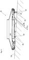
- FIG. 14 shows together with the FIGS. 15 and 16 a plate 300, which is bendable and / or bendable, and which is substantially in the form of a polygon, in this case a rectangle, is executed.
- the plate 300 at a first side 302 (in the FIG. 14 bottom) in the present case six recesses 304 open towards the first side 302, wherein, starting from an edge 302a of the first side 302, the recess 304 comprises a first portion 304a which extends at least approximately at right angles to the edge 302a, and wherein starting from the first portion 304a, the recess 304 comprises a second portion 304b which extends at least approximately parallel to the edge 302a. See also the FIG. 15 ,
- the first portion 304a has an angle of approximately 70 ° to 110 °, preferably from approximately 80 ° to approximately 100 °, with respect to the edge 302a. In the present case, this angle is approximately 90 °.
- the second portion 304b has an angle of from about + 10 ° to about -10 °, preferably from about + 4 ° to about -4 °, with respect to the edge 302a. In the present case, this angle is approximately 0 °.
- the first and second sections 304a and 304b each have at least approximately a constant width (without reference numerals).
- the plate 300 on at least one second side 306 has at least one recess 308 open towards the second side 306, wherein the second side 306 preferably lies opposite the first side 302.
- the present four recesses 308 on the second side 306 have a shape comparable at least approximately to the at least one recess 304 of the first side 302.
- the recesses 308 respectively include a first portion 308a, a second portion 308b, and a local constriction 308c, respectively FIG. 16 , As in FIG. 14 Further, a width of the first and / or the second portion 308a or 308b of the second recess 308 is smaller than a comparable width of the first recess 304.
- two or more recesses 304 and 308 are respectively arranged on the first and on the second side 302 or 306 of the plate 300, at least one distance between two recesses 304 on the one side 302 being different along the edge 302a or 306a is at a distance between two comparable recesses 308 on the other side 306.
- a thickness of the plate 300 is less than or equal to 10 mm, millimeters, preferably less than or equal to 5 mm, even more preferably less than or equal to 2 mm.
- the plate 300 comprises a metal and / or a plastic material and / or a cardboard material.
- an outer lateral surface of the hollow cylinder 222 has an embossed, printed, pasted and / or painted textual and / or pictorial information 310. This is exemplified by a capital letter "P".
- the plate 300 has a plurality of elements, which are consecutively strung together in a plane of the plate 300 and connected to each other.
- the elements are designed as slats, similar to the case of shutters.
- the compound is the Elements bendable, rotatable and / or articulated executed.
- the elements have defined bending points ("bendable"), for example by means of local reductions in the thickness of the plate 300. This is also known as the so-called "film hinge”.
- the elements have on a first longitudinal side rod-shaped "axes" and correspondingly on a second longitudinal side annular "sockets"("rotatable”).
- two elements each hook-shaped ("hinged"), similar, as is known from shutters.
- the plate 300 obtains a "bendable” and / or “bendable” property and can be formed corresponding to the hollow cylinder 222.
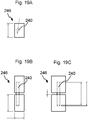
- FIGS. 17A to 17C . 18A to 18C and 19A to 19C show an embodiment of the table top 200, wherein the table top 200 comprises two substantially semicircular executed partial table tops 200a and 200b.
- the one partial table top 200a has a groove (FIG. FIGS. 17A to 17C ) and the other partial table top 200b a spring ( FIGS. 18A to 18C ) on.
- the funds include present rod-shaped elements which can be arranged in the in a plane of the table top 200 extending bores 206 of the partial table tops 200a and 200b.
- the table top 200 is given sufficient mechanical stability.
- locking means 210 or snap connector are present (see FIG. 12 ) to connect the sub-table tops 200a and 200b in a defined manner.
- FIGS. 19A to 19C each show 90 ° folded views of the bolt-holding device 246th
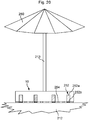
- the sunshade 250 includes the holding tube 213, which by means of an in FIG. 20 non-visible holding device 238 (see Figures 12 and 13 ) is held in the base 10.
- the holding tube 213 is designed as a unit with the sunshade 250.
- the object 250 to be erected is a Christmas tree, a table or a chair, for example an office chair.
- a ratio of the volume of the first partial body 252a to the volume of the second partial body 252b has a value greater is equal to 1, preferably greater than or equal to 20, even more preferably greater than or equal to 500.
- the second part of the body 252b can therefore be made comparatively thin, but this is not absolutely necessary.
- the second partial body 252b has a modulus of elasticity greater than 0.3 kN / mm 2, kilonewtons per square millimeter, preferably greater than 10 kN / mm 2, even more preferably greater than 25 kN / mm 2.
- a specific "ceramic” typically has a modulus of elasticity of from about 0.3 to about 30 kN / mm 2.
- a Shore D hardness of the second partial body 252b can be greater than 80, preferably greater than 100, even more preferably greater than 150.
- the pedestal 10 comprises a secondary sliding element or secondary support element 254, wherein, in particular in an unloaded state, the primary support element 252 extends farther out of a base plane of the pedestal 10 than the secondary support element 254. This will be described in the following FIG. 21 to be shown.
- the secondary support member 254 a lower housing portion or a bottom of the base 10, wherein the base 10 is thus executed on its the support surface 212 facing bottom substantially flat.
- the secondary support element 254 has a modulus of elasticity greater than or equal to 0.1 kN / mm 2, kilonewtons per square millimeter, preferably greater than or equal to 5 kN / mm 2.
- the base 10 is designed such that a (the support surface 212 facing) surface of the second body part 252 b of the primary support member 252 with respect to a reference surface (corresponding to the support surface 212, for example) has a first coefficient of friction, wherein a surface of the secondary support member 254 has a second coefficient of friction greater than the first coefficient of friction relative to the same reference surface.
- the primary support member 252 comprises a composite material, wherein at least a first component of the composite comprises a rubber elastic material. In particular, while the resilient property of rubber is exploited.
- At least one further support element is provided, which comprises at least one roller, roller, or rollable ball.
- the primary support element 252 is arranged on a base body of the base 10 by means of a spring which can be subjected to pressure, preferably a helical spring or leaf spring.
- a constant of elasticity or a spring constant for the primary support element 252 is predetermined such that when the base 10 is loaded with a first weight force, the at least one primary support element 252 complementary to the at least one secondary Support element 254 can press against the support surface 212 ( FIG. 20 ), and that when the stand 10 is loaded with a second weight force, which is smaller than the first weight force that can lift at least one secondary support element 254 of the support surface 212 ( FIG. 21 ).
- the object to be erected 250 is a table, for example a one-legged table, which is thus arranged on a base 10.
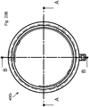
- the Figure 22A shows according to a line AA of Figure 22C a sectional view of a substantially rotationally symmetrical running lower threaded sleeve 400a of the first adapter device 400 for holding the object to be placed 250. See also the Figures 12 and 13 ,
- the lower threaded sleeve 400a includes an internal thread 402 and a centering mandrel 404.
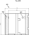
- the Figure 24B shows a first radial view of the second adapter device 420.
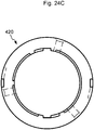
- the Figure 24C shows a second radial view of the second adapter device 420.
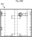
- the Figure 24D shows a further view ("bottom view") of the second adapter device 420.
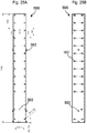
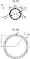
- FIGS. 25A to 25D show for a further embodiment of the base 10 a substantially designed as a hollow cylinder support tube 500 which is arranged concentrically to the longitudinal axis 224 of the base 10 on the base 10 (or can be arranged), wherein the support tube 500 is adapted to be erected Object 250, in particular the table top 200 to wear.
- the support tube 500 is configured to support a seat surface and / or a backrest of a chair, for example an office chair.
- the support tube 500 has a diameter of 50 mm to 200 mm, preferably about 80 mm to 90 mm.
- the support tube 500 has a plurality of openings 502 which each extend in radial planes of the support tube 500. As in the Figures 25A and 25B can be seen, the openings 502 are partially aligned centrally and partially not centric. In the majority, the openings 502 are arranged in an axial pitch.
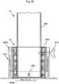
- the support tube 500 may be held on the base 10 by means of at least one adapter device 400 or 420 designed at least approximately as a hollow cylinder. This is sketchy in the FIG. 26 shown.
- FIG. 26 shows the lower threaded sleeve 400a, in which the upper screw 400b is screwed.
- the lower one Screwing sleeve 400a forms, together with the upper threaded sleeve 400b, the first adapter device 400.
- the second adapter device 420 in a radially inner portion of the upper threaded sleeve 400b, the second adapter device 420 (see FIGS FIGS. 24A to 24D ) arranged.
- FIG. 26 thus, an embodiment of the base 10, in which the support tube 500 is held in a form-fitting manner on the base 10, and wherein the support tube 500 and / or the at least one adapter device 400 and 420 is held by means of at least one screw 412 on the base 10.
- the support tube 500 and / or the at least one adapter device 400 and 420 is held by means of at least one screw 412 on the base 10.
- that in the FIG. 1 merely indicated holding device 12 in the FIG. 26 shown elements.
- the sleeve insertion technique with the bolts is particularly advantageous because it is much faster to assemble than, for example, bolted pipes. Also, except for the deepened in the table tops 200 and 200a and 200b recessed fasteners on the bottom of the table tops 200 and 200a and 200b no other means of connection can be seen, which also leads to a very delicate appearance of the table tops on the support tube, if this particular should be hung high, so that a viewer sees the underside of the tabletop. In addition, there is a very low stack height for the table tops 200 and 200a and 200b during transport. It corresponds exactly to the table top thickness, since all connecting elements recessed in the table tops 200 and 200a and 200b are embedded.
- the two tabletop halves 200a and 200b are each equipped with tongue and groove. If square or rectangular table tops 200 or 200a and 200b are fastened with at least two feet 10 each having a support tube 500 with the same connector, a panel can also be set up. If additional corner pieces are used, then L- or T- or U-shaped table surfaces 200 or 200a and 200b can be set up, in which case the parasols 250 can then also be inserted into the support tubes 500.
- a radially inner region of the second adapter device 420 in the present case has a diameter of approximately 85 millimeters (see Figure 24A ).
- a diameter-compatible umbrella pole or a holding tube 213 can be set, or the support tube 500.
- fixing screws in particular one or more screw 412
- the base 10 with the support tube 500 then characterizes a monolithic unit.
- a large diameter of the support tube 500 has the advantage that a large internal lever arm is very advantageous for power transmission.
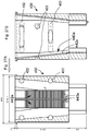
- Figs. 27A to 27G 14 show several views of a third adapter device 430 for a further embodiment of the pedestal 10, wherein the third adapter device 430 has at least one radially acting clamping device 440, and wherein a radial dimension of the clamping device 440 is substantially infinitely adjustable.
- an outer diameter of the third adapter device 430 below the upper edge present 79.1 millimeters. This dimension corresponds to an upper inner diameter of the support tube 500 according to the FIGS. 25A to 25D .
- the third adapter device 430 can be arranged radially inside the support tube 500.
- the third adapter device 430 may be arranged in an end section of the support tube 500 facing away from the table leg.
- Openings 432 on the third adapter device 430 are arranged at an axial distance of the adapter device 430 in such a way that they are congruent with the axially arranged openings 502 of the support tube 500, in the event that the adapter device 430 is fully inserted from above into the support tube 500. or inserted positively.
- the adapter device 430 can be used both in the adapter device 400 and in the support tube 500.
- the fixing of the adapter device 430 takes place in the upper screw sleeve 400b by screwing the screw connection 412 into a screw-in recess 433 (see FIGS Figures 27B . 27F and 27G ) of the adapter device 430.
- the clamping device 440 comprises at least one first clamping element 440a which, in particular substantially rigidly, can be coupled to the base 10, wherein the clamping device 440 has at least one second clamping element 440b (see FIGS Figures 28A and 28B ) radially disposed between the first clamping member 440a and the object 250 to be placed, and wherein the first clamping member 440a has a first contact surface 442a and the second clamping member 440b has a second contact surface 442b, wherein the first and second contact surfaces 442a and 442b at least partially contact, wherein in particular a contact surface has an area of at least about 20 square millimeters.
- the first and / or the second contact surface 442a or 442b preferably has a ripple or the like which, for example, is wave-shaped, sinusoidal, semicircular, sawtooth-shaped or triangular. Also comparatively "smooth" contact surfaces 442a and 442b are possible, wherein a respective friction causes the desired effect.
- the first and / or the second contact surface 442a or 442b may also have, at least in sections, another type of structure, in particular random and / or regular surface structuring, which enables a frictional connection and / or positive connection between the contact surfaces 442a and 442b.
- first and / or the second contact surface 442a and 442b at least partially, preferably formed predominantly flat.
- the first and / or the second contact surface 442a or 442b is formed flat for more than 90% of a total area.
- the first and / or the second contact surface 442a or 442b is formed substantially rectangular, wherein a width of the first and the second contact surface 442a and 442b is smaller than a length of the first and the second contact surface 442a and 442b, and wherein a longitudinal axis (without reference numeral) of the first and the second contact surface 442a and 442b with the longitudinal axis 224 of the base 10 preferably forms an angle between about 2 ° and about 45 °, in particular between about 5 ° and about 30 °.
- the first and the second clamping element 440a and 440b are each at least partially designed as a so-called inclined plane, these sections are complementary to each other. Compare the below FIG. 28B ,
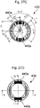
- the Figure 27A shows a sectional view of the third adapter device 430 according to a line BB of Figure 27D , In particular, the first one To recognize contact surface 442a, which is divided here in a vertical direction in the drawing in individual areas, see also the Figures 27C, 27D and 27F ,
- the Figure 27B shows a sectional view of the third adapter device 430 according to a line CC of Figure 27D ,
- FIG. 27C and FIG. 27D respectively show a first and a second radial view of the third adapter device 430
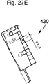
- Figure 27E shows a sectional view along a line DD of Figure 27C
- the Figure 27F shows a "bottom view”.
- the Figure 27G shows an auxiliary view.
- the Figures 27C to 27G wise in relation to the Figures 27A and 27B a reduced scale.
- the Figure 28A shows the second clamping element 440b in a perspective view.
- the FIG. 28B 10 shows a schematic diagram of the clamping device 440, wherein a radial dimension 444 is variable in dependence on a relative position of the clamping elements 440a and 440b.
- the Figure 28C shows a perspective view of the third adapter device 430 with two arranged in a radially inner region of the adapter device 430 second clamping elements 440 b.
- at least one surface of at least one clamping element preferably a surface of the second clamping elements 440b, in particular a surface opposite the first or second contact surface 442a or 442b, at least in sections has a geometry of a clothoid.
- the holding tube 213 can be held firmly between the two second clamping elements 440b largely independently of a diameter of the holding tube 213.
Landscapes
- Engineering & Computer Science (AREA)
- Architecture (AREA)
- Civil Engineering (AREA)
- Structural Engineering (AREA)
- Non-Portable Lighting Devices Or Systems Thereof (AREA)
- Details Of Rigid Or Semi-Rigid Containers (AREA)
- Furniture Connections (AREA)
- Chair Legs, Seat Parts, And Backrests (AREA)
- Pallets (AREA)
- Walking Sticks, Umbrellas, And Fans (AREA)
- Toys (AREA)
- Refuge Islands, Traffic Blockers, Or Guard Fence (AREA)
Claims (17)
- Pied d'appui (10, 10b) comprenant un dispositif de support (12) permettant de maintenir un objet (250) à dresser, comprenant une zone de réception (20) permettant de recevoir un poids de lestage amovible (60) dans une position de réception (24), la position de réception (24) étant située radialement vers l'extérieur, et, à partir de cette position de réception (24) située radialement vers l'intérieur, étant positionnée dans la direction périphérique, au moins par segments, une zone relevée (28), comprenant une surface de transport (32) qui est de préférence adjacente à la zone de réception (20), le pied d'appui (10, 10b) comprenant une zone d'entrée (44) dans laquelle peut être introduit le poids de lestage (60), et qui est réalisée de sorte que, après son introduction, le poids de lestage (60) se déplace sous l'action de sa gravité sur la surface de transport (32), de préférence par roulement et/ou par glissement dans la position de réception (24), caractérisé en ce qu'entre le dispositif de support (12) et la zone d'entrée (44) est positionné un dispositif d'introduction (90) qui comporte une surface d'introduction (94) qui a essentiellement la forme d'une surface enveloppe d'un tronc de cône, et est globalement inclinée par rapport à la face d'appui (40) d'un angle compris entre 7° et 35°, de préférence entre 12° et 25°, et en particulier entre 15° et 20°.
- Pied d'appui (10, 10b) conforme à la revendication 1, caractérisé en ce que la surface de transport (32) est globalement inclinée par rapport à la face d'appui (40) d'un angle (36) compris entre 5° et 30°, de préférence entre 10° et 22° et en particulier entre 12° et 18°, et en particulier, la surface de transport (32) a essentiellement la forme de la surface enveloppe d'un tronc de cône.
- Pied d'appui (10, 10b) conforme à au moins l'une des revendications précédentes, caractérisé en ce qu'il comporte un élément supérieur (14) et un élément inférieur (16) qui sont reliés de façon amovible et inamovible, et, l'élément supérieur (14) délimite la zone de réception (20) en direction de la face supérieure (84) et l'élément inférieur (16) délimite la zone de réception (20) en direction de la face d'appui (40).
- Pied d'appui (10, 10b) conforme à au moins l'une des revendications précédentes, caractérisé en ce que sur la face d'appui (40) comporte une zone saillante (80), et la face supérieure (84) comporte une zone en retrait (88), qui est complémentaire de la zone saillante (80) de sorte que la zone saillante (80b) d'un second pied d'appui (10b) essentiellement identique puisse être introduite dans la zone en retrait (88), de préférence par une liaison par la forme et/ou par une liaison par la force.
- Pied d'appui (10, 10b) conforme à au moins l'une des revendications précédentes, caractérisé en ce qu'il comporte au moins un élément de support primaire (252) comportant un premier corps partiel (252a) déformable élastiquement et au moins un second corps partiel (252b) renfermant un matériau céramique qui est situé sur le premier corps partiel (252a), et, en particulier le pied d'appui (10) comporte au moins un élément de support secondaire (254), et, notamment à l'état non chargé l'élément de support primaire (252) dépasse plus du plan de la surface de base du pied d'appui (10) que l'élément de support secondaire (254).
- Pied d'appui (10, 10b) conforme à au moins l'une des revendications précédentes, comportant un tube porteur (500) essentiellement réalisé sous la forme d'un cylindre creux qui est monté sur le pied d'appui (10) concentriquement à son axe longitudinal (224), et en particulier le tube porteur (500) est maintenu sur le pied d'appui (10) au moyen d'au moins un dispositif adaptateur (400, 420) réalisé au moins essentiellement sous la forme d'un cylindre creux.
- Pied d'appui (10, 10b) conforme à au moins l'une des revendications précédentes, caractérisé en ce qu'il comporte une surface d'appui (214) prévue pour son positionnement sur une surface porteuse (212), et une surface de réception (216) essentiellement opposée à la surface d'appui (214), et, dans la zone de la surface de réception (216) est prévu un dispositif de réception (220) comprenant au moins une rainure (218) permettant de recevoir un cylindre creux (222).
- Pied d'appui (10, 10b) conforme à la revendication 7, comportant un cylindre creux (222) qui est logé dans le dispositif de réception (220), ainsi qu'une tablette (200) qui est montée sur le segment d'extrémité du cylindre creux (222) opposé au pied d'appui (10).
- Pied d'appui (10, 10b) conforme à au moins l'une des revendications précédentes, dans lequel le dispositif de support (12) comporte au moins un dispositif adaptateur (430) permettant de maintenir l'objet (250) à dresser, et le dispositif adaptateur (430) comporte au moins un dispositif de serrage (440) agissant radialement, la dimension radiale du dispositif de serrage (440) étant réglable de façon essentiellement continue.
- Pied d'appui (10, 10b) conforme à la revendication 9, dans lequel le dispositif de serrage (440) comporte au moins un premier élément de serrage (440a) qui peut être couplé en particulier de façon essentiellement rigide avec le pied d'appui (10), ainsi qu'au moins un second élément de serrage (440b) qui peut être positionné radialement entre le premier élément de serrage (440a) et l'objet à dresser (250), le premier élément de serrage (440a) comprenant une première surface de contact (442a) et le second élément de serrage (440b) comprenant une seconde surface de contact (442b), la première surface de contact et la seconde surface de contact (442a, 442b) venant en contact au moins par segments, et en particulier une surface de contact a une surface d'au moins environ 20 millimètres carrés et en particulier la première surface de contact et/ou la seconde surface de contact (442a, 442b) est (sont) plane(s) au moins par segments et de préférence de façon prépondérante.
- Pied d'appui (10, 10b) conforme à la revendication 10, dans lequel la première surface de contact et/ou la seconde surface de contact (442a, 442b) est(sont) essentiellement rectangulaire(s) et la largeur de la première surface de contact ou de la seconde surface de contact (442a, 442b) est inférieure à la longueur de la première surface de contact ou de la seconde surface de contact (442a, 442b) et l'axe longitudinal de la première surface de contact ou de la seconde surface de contact (442a, 442b) définit de préférence avec l'axe longitudinal (224) du pied d'appui (10) un angle compris entre environ 2° et environ 45°, en particulier entre environ 5° et environ 30°.
- Pied d'appui (10, 10b) conforme à l'une des revendications 10 et 11, dans lequel au moins une surface d'au moins un élément de serrage (440a, 440b) de préférence une surface du second élément de serrage (440b), en particulier une surface située à l'opposé de la première surface de contact ou de la seconde surface de contact (442a, 442b) a au moins par segment la géométrie d'une courbe clothoïde.
- Pied d'appui (10, 10b) conforme à au moins l'une des revendications précédentes, dans lequel il est prévu au moins un poids de lestage (60) permettant d'alourdir le pied d'appui (10, 10b), le poids de lestage (60) comprenant un ensemble d'éléments de lestage (64) flexibles reliés ou pouvant être reliés les uns aux autres, et de préférence un ensemble de poids indépendants ou d'éléments de lestage flexibles (64) reliés entre eux essentiellement en forme de sphère, de cylindre, ou de tonneau.
- Pied d'appui (10, 10b) conforme à au moins l'une des revendications précédentes, dans lequel dans le dispositif de support (12, 12b) est monté un insert de support (118, 118b), et, en particulier, l'insert de support (118, 118b) est réalisé sous la forme d'un élément adaptateur (120, 120b) en forme de cylindre creux et est monté ou peut être monté dans la cavité interne (124, 124b) de l'élément adaptateur en forme de cylindre creux (120, 120b) de l'objet à dresser (250), et, en particulier, l'objet à dresser (250) est monté ou peut être monté dans la cavité interne (124, 124b) par une liaison par la force.
- Pied d'appui (10, 10b) conforme à la revendication 14, dans lequel l'insert de support (118, 118b) comporte une surface d'appui (128, 128b).
- Pied d'appui (10, 10b) conforme à au moins l'une des revendications précédentes, dans lequel la face d'appui (40) comporte une zone relevée (80) et la face supérieure (84) comporte une zone en retrait (88) qui est complémentaire à la zone relevée (80) de sorte qu'une zone relevée (80b) d'un second pied d'appui (10b) essentiellement identique puisse être introduite, de préférence par une liaison par la forme et/ou par une liaison par la force dans la zone en retrait (88), dans chaque dispositif de support (12, 12b) du pied d'appui (10, 10b) étant montés des inserts de support (118, 118b), comprenant une surface d'appui (128, 128b), la surface d'appui (128) du premier pied d'appui (10) venant en contact avec les zones relevées (80b) du second pied d'appui (10b), et en particulier la surface d'appui (128) étant réalisée de façon à transférer sur la face d'appui (40) du premier pied d'appui (10) les forces agissant en raison du poids du second pied d'appui (10b).
- Pied d'appui conforme à au moins l'une des revendications 14 à 16, dans lequel l'insert de support (118, 118b) est constitué par un manchon cylindrique qui est réalisé avec un volume de réception essentiellement en forme de cylindre ouvert vers la face supérieure (84) du pied d'appui (10, 10b) respectif, et en particulier, le manchon comporte au moins un boulon fileté pouvant être vissé dans le volume de réception.
Priority Applications (2)
| Application Number | Priority Date | Filing Date | Title |
|---|---|---|---|
| EP18183051.4A EP3415703B1 (fr) | 2014-07-08 | 2015-07-06 | Pied support |
| PL18183051T PL3415703T3 (pl) | 2014-07-08 | 2015-07-06 | Stojak |
Applications Claiming Priority (2)
| Application Number | Priority Date | Filing Date | Title |
|---|---|---|---|
| DE102014213203.7A DE102014213203B3 (de) | 2014-07-08 | 2014-07-08 | Standfuß |
| PCT/EP2015/065348 WO2016005321A1 (fr) | 2014-07-08 | 2015-07-06 | Support |
Related Child Applications (2)
| Application Number | Title | Priority Date | Filing Date |
|---|---|---|---|
| EP18183051.4A Division-Into EP3415703B1 (fr) | 2014-07-08 | 2015-07-06 | Pied support |
| EP18183051.4A Division EP3415703B1 (fr) | 2014-07-08 | 2015-07-06 | Pied support |
Publications (2)
| Publication Number | Publication Date |
|---|---|
| EP3140475A1 EP3140475A1 (fr) | 2017-03-15 |
| EP3140475B1 true EP3140475B1 (fr) | 2018-08-29 |
Family
ID=53185729
Family Applications (2)
| Application Number | Title | Priority Date | Filing Date |
|---|---|---|---|
| EP15734662.8A Active EP3140475B1 (fr) | 2014-07-08 | 2015-07-06 | Support |
| EP18183051.4A Active EP3415703B1 (fr) | 2014-07-08 | 2015-07-06 | Pied support |
Family Applications After (1)
| Application Number | Title | Priority Date | Filing Date |
|---|---|---|---|
| EP18183051.4A Active EP3415703B1 (fr) | 2014-07-08 | 2015-07-06 | Pied support |
Country Status (8)
| Country | Link |
|---|---|
| US (1) | US10487528B2 (fr) |
| EP (2) | EP3140475B1 (fr) |
| JP (1) | JP6667516B2 (fr) |
| CN (1) | CN206591897U (fr) |
| DE (4) | DE102014213203B3 (fr) |
| ES (1) | ES2802300T3 (fr) |
| PL (1) | PL3415703T3 (fr) |
| WO (1) | WO2016005321A1 (fr) |
Families Citing this family (35)
| Publication number | Priority date | Publication date | Assignee | Title |
|---|---|---|---|---|
| DE102012006409B4 (de) * | 2012-03-30 | 2022-05-19 | Carl Zeiss Meditec Ag | Stativfuß für ein Operationsmikroskop, Gewichtsmodul für einen solchen Stativfuß und System umfassend zwei solcher Gewichtsmodule |
| US10087647B2 (en) * | 2016-03-21 | 2018-10-02 | Premier Tents, Inc. | Weight systems and methods stabilizing objects |
| US10509437B2 (en) * | 2018-01-08 | 2019-12-17 | Lenovo (Singapore) Pte. Ltd. | Digital assistant device |
| AU2019250646B2 (en) * | 2018-04-13 | 2025-05-08 | Dmmac Limited | Systems, methods, and modules for supporting a pole |
| US10745872B2 (en) * | 2018-04-18 | 2020-08-18 | SignsDirect Inc. | Sign with planter base |
| US20200260712A1 (en) * | 2019-02-15 | 2020-08-20 | Novelty Manufacturing Co. | Insect trap |
| USD934554S1 (en) * | 2019-02-20 | 2021-11-02 | Aksimo Distribution Ltd. | Umbrella base weight bag |
| USD919955S1 (en) * | 2019-02-20 | 2021-05-25 | Amiram Kohen | Umbrella base weight bag |
| USD919282S1 (en) * | 2019-02-21 | 2021-05-18 | Amiram Kohen | Umbrella base weight bag set |
| US11353117B1 (en) | 2020-01-17 | 2022-06-07 | Vulcan Industrial Holdings, LLC | Valve seat insert system and method |
| US11136781B1 (en) | 2020-04-08 | 2021-10-05 | Premier Tents, Inc. | Container assembly systems and methods and combination of container assembly and weight material assembly for stabilizing objects |
| US11421679B1 (en) | 2020-06-30 | 2022-08-23 | Vulcan Industrial Holdings, LLC | Packing assembly with threaded sleeve for interaction with an installation tool |
| US11421680B1 (en) | 2020-06-30 | 2022-08-23 | Vulcan Industrial Holdings, LLC | Packing bore wear sleeve retainer system |
| US12049889B2 (en) | 2020-06-30 | 2024-07-30 | Vulcan Industrial Holdings, LLC | Packing bore wear sleeve retainer system |
| US11384756B1 (en) | 2020-08-19 | 2022-07-12 | Vulcan Industrial Holdings, LLC | Composite valve seat system and method |
| USD986928S1 (en) | 2020-08-21 | 2023-05-23 | Vulcan Industrial Holdings, LLC | Fluid end for a pumping system |
| USD997992S1 (en) | 2020-08-21 | 2023-09-05 | Vulcan Industrial Holdings, LLC | Fluid end for a pumping system |
| USD980876S1 (en) | 2020-08-21 | 2023-03-14 | Vulcan Industrial Holdings, LLC | Fluid end for a pumping system |
| US12366245B1 (en) | 2020-08-27 | 2025-07-22 | Vulcan Industrial Holdings, LLC | Connecting rod assembly for reciprocating pump |
| PL4006232T3 (pl) * | 2020-11-25 | 2024-04-02 | Ab Varmförzinkning | Fundament do podparcia słupka oraz układ poprawiający bezpieczeństwo w połączeniu z konstrukcjami wsporczymi wyposażenia drogowego |
| US12055221B2 (en) | 2021-01-14 | 2024-08-06 | Vulcan Industrial Holdings, LLC | Dual ring stuffing box |
| US11391374B1 (en) | 2021-01-14 | 2022-07-19 | Vulcan Industrial Holdings, LLC | Dual ring stuffing box |
| US12292120B1 (en) | 2021-02-23 | 2025-05-06 | Vulcan Industrial Holdings, LLC | System and method for valve assembly |
| US11846356B1 (en) | 2021-08-18 | 2023-12-19 | Vulcan Industrial Holdings, LLC | Self-locking plug |
| US12510164B1 (en) | 2021-08-18 | 2025-12-30 | Vulcan Industrial Holdings, LLC | Sleeved fluid end |
| USD974738S1 (en) * | 2022-01-06 | 2023-01-10 | Xiujuan Song | Umbrella base |
| US12140240B1 (en) | 2022-01-19 | 2024-11-12 | Vulcan Industrial Holdings, LLC | Gradient material structures and methods of forming the same |
| US12297922B1 (en) | 2022-03-04 | 2025-05-13 | Vulcan Industrial Holdings, LLC | Valve seat with embedded structure and related methods |
| US11434900B1 (en) | 2022-04-25 | 2022-09-06 | Vulcan Industrial Holdings, LLC | Spring controlling valve |
| GB2618586B (en) * | 2022-05-11 | 2024-05-22 | Three Smith Group Ltd | Connector assembly |
| US11920684B1 (en) | 2022-05-17 | 2024-03-05 | Vulcan Industrial Holdings, LLC | Mechanically or hybrid mounted valve seat |
| USD1113987S1 (en) | 2022-05-20 | 2026-02-17 | Vulcan Industrial Holdings, LLC | Header ring for a pumping system |
| USD1061623S1 (en) | 2022-08-03 | 2025-02-11 | Vulcan Industrial Holdings, LLC | Fluid end for a pumping system |
| US12292121B2 (en) | 2023-08-10 | 2025-05-06 | Vulcan Industrial Holdings, LLC | Valve member including cavity, and related assemblies, systems, and methods |
| USD1043096S1 (en) * | 2023-09-15 | 2024-09-24 | Shenzhen Youchong Technology Co., Ltd. | Umbrella base |
Family Cites Families (34)
| Publication number | Priority date | Publication date | Assignee | Title |
|---|---|---|---|---|
| US2613899A (en) * | 1950-02-15 | 1952-10-14 | Wagner Samuel | Christmas tree stand |
| US2952471A (en) * | 1956-11-26 | 1960-09-13 | Allen & Hanburys Ltd | Wheeled trolleys |
| DE1126761B (de) * | 1959-08-29 | 1962-03-29 | Netzfabrikation Karl Weisse | Netz von rechteckiger Form zum Bergen von Gegenstaenden aus dem Wasser |
| DE1834139U (de) * | 1961-04-01 | 1961-07-06 | Eisenwarenfabrik Selbach | Fuss fuer gartenschirmstaender, garderobenstaender od. dgl. |
| US3415475A (en) * | 1966-10-13 | 1968-12-10 | Robert R. Goodman | Weighted base |
| US3794279A (en) * | 1972-04-24 | 1974-02-26 | Hy Kramer Enterprise Inc | Portable pedestal for lawn umbrellas, stanchions, and the like |
| US3841631A (en) * | 1973-07-09 | 1974-10-15 | E Dolan | Portable basketball backstop construction |
| US4145044A (en) * | 1977-03-07 | 1979-03-20 | The Ohio Art Company | Portable basketball set |
| DE3627084A1 (de) * | 1986-08-09 | 1988-02-11 | Waldenfels Roderich Freiherr V | Reinigungsgeraet fuer schusswaffen |
| IT221926Z2 (it) * | 1991-10-02 | 1994-12-29 | Dina Warenhandels Gmbh & Co Kg | Struttura di supporto, particolarmente studiato per ombrelloni e coperture di spazi aperti in genere |
| US5220740A (en) * | 1992-07-06 | 1993-06-22 | Brault Bertrand W | Movable stand |
| DE29604992U1 (de) * | 1996-03-18 | 1996-09-26 | Becker, Johannes, 86836 Graben | Schirm |
| FR2752003B1 (fr) * | 1996-08-01 | 1998-11-27 | Georges David Ets | Pied de parasol |
| US5878518A (en) * | 1996-10-28 | 1999-03-09 | Marketing Displays, Inc. | Sign stand with rolling base |
| US5875578A (en) * | 1996-10-28 | 1999-03-02 | Marketing Displays, Inc. | Sign stand with rolling base |
| DE29819022U1 (de) * | 1998-10-26 | 1999-01-07 | Ebenthal, Norbert, 27239 Twistringen | Schirmständer, insbesondere für einen Sonnenschirm |
| DE50012420D1 (de) * | 1999-02-07 | 2006-05-11 | Leica Microsystems | Stativ, insbesondere Mikroskopstativ |
| US20010011695A1 (en) * | 1999-02-16 | 2001-08-09 | D. Lee Hill | Pedestal apparatus |
| US6427963B1 (en) * | 1999-03-24 | 2002-08-06 | Huffy Corporation | Rollable sports base |
| US20030145498A1 (en) * | 2001-04-09 | 2003-08-07 | Frank Venegas | Portable sign support apparatus |
| US6889953B2 (en) * | 2002-09-19 | 2005-05-10 | Southern Sales & Marketing Group, Inc. | Umbrella stand |
| CN2580860Y (zh) * | 2002-10-09 | 2003-10-22 | 吴伟淡 | 组合式太阳伞底盘 |
| JP3689693B2 (ja) | 2002-12-25 | 2005-08-31 | 株式会社安田化成 | ポール等の支持台 |
| US6869058B2 (en) * | 2003-06-17 | 2005-03-22 | Benson Tung | Base assembly for a sunshade |
| US20050189005A1 (en) | 2003-12-29 | 2005-09-01 | Smith James C. | Umbrella base |
| US7584563B2 (en) * | 2004-12-08 | 2009-09-08 | Marketing Displays, Inc. | Sign stand with rolling base |
| US7216839B2 (en) * | 2005-08-30 | 2007-05-15 | Sun Xiaoqiu | Water-injection rack base for mast |
| US7958670B2 (en) * | 2006-10-04 | 2011-06-14 | Maria N Kamau | Decorative pole and base stand stabilizing container |
| DE102007012223A1 (de) * | 2007-03-12 | 2008-09-18 | Yotrio Group Co.Ltd., Linhai | Mastständer |
| US8919361B2 (en) * | 2010-07-02 | 2014-12-30 | Oliver Joen-An Ma | Movable base with wheels deployable by cyclic driving assembly |
| US8968047B1 (en) * | 2011-05-09 | 2015-03-03 | Balloon Innovations, LLC | Balloon display system with inflatable balloon, balloon holder cup and flexible rod with mounting pole |
| KR101929892B1 (ko) * | 2011-10-24 | 2018-12-18 | 삼성전자주식회사 | 휴대용 단말기의 거치대 |
| US20130146739A1 (en) * | 2011-12-09 | 2013-06-13 | Lifeng Zhao | Portable kd umbrella base |
| US8807513B2 (en) * | 2012-05-21 | 2014-08-19 | Dee Volin | Unique multi-adjustable rotating-and-locking umbrella-stanchion system |
-
2014
- 2014-07-08 DE DE102014213203.7A patent/DE102014213203B3/de not_active Expired - Fee Related
-
2015
- 2015-04-20 DE DE202015002823.3U patent/DE202015002823U1/de not_active Expired - Lifetime
- 2015-05-02 DE DE202015003248.6U patent/DE202015003248U1/de not_active Expired - Lifetime
- 2015-05-05 DE DE202015003225.7U patent/DE202015003225U1/de not_active Expired - Lifetime
- 2015-07-06 ES ES18183051T patent/ES2802300T3/es active Active
- 2015-07-06 WO PCT/EP2015/065348 patent/WO2016005321A1/fr not_active Ceased
- 2015-07-06 EP EP15734662.8A patent/EP3140475B1/fr active Active
- 2015-07-06 US US15/322,806 patent/US10487528B2/en active Active
- 2015-07-06 EP EP18183051.4A patent/EP3415703B1/fr active Active
- 2015-07-06 PL PL18183051T patent/PL3415703T3/pl unknown
- 2015-07-06 CN CN201590000322.4U patent/CN206591897U/zh not_active Expired - Lifetime
- 2015-07-06 JP JP2017521298A patent/JP6667516B2/ja active Active
Also Published As
| Publication number | Publication date |
|---|---|
| JP6667516B2 (ja) | 2020-03-18 |
| US20170130481A1 (en) | 2017-05-11 |
| DE202015003248U1 (de) | 2015-10-14 |
| EP3415703B1 (fr) | 2020-04-01 |
| CN206591897U (zh) | 2017-10-27 |
| US10487528B2 (en) | 2019-11-26 |
| ES2802300T3 (es) | 2021-01-18 |
| DE202015002823U1 (de) | 2015-05-06 |
| DE202015003225U1 (de) | 2015-10-14 |
| EP3415703A1 (fr) | 2018-12-19 |
| WO2016005321A1 (fr) | 2016-01-14 |
| DE102014213203B3 (de) | 2015-07-02 |
| JP2017532514A (ja) | 2017-11-02 |
| EP3140475A1 (fr) | 2017-03-15 |
| PL3415703T3 (pl) | 2020-09-07 |
Similar Documents
| Publication | Publication Date | Title |
|---|---|---|
| EP3415703B1 (fr) | Pied support | |
| WO2010086166A1 (fr) | Support pour arbre | |
| DE102014014427A1 (de) | Stielgeführtes Werkzeug und Stützvorrichtung zum Abstellen eines stielgeführten Werkzeuges | |
| EP3011866B1 (fr) | Pied de table et table | |
| DE4442747C2 (de) | Modulares Regalsystem | |
| EP1257185B1 (fr) | Element de raccordement pour un meuble, notamment pour une table | |
| WO2009092615A1 (fr) | Structure support pour matériau plat pouvant être étendu, notamment pour former un corps creux | |
| DE20015250U1 (de) | Höhenverstelleinrichtung für Stützelemente, insbesondere für Tischbeine od.dgl. | |
| DE10312160B4 (de) | Einrichtung zum lösbaren Verbinden eines Stützelementes mit einem zu tragenden Objekt | |
| DE102023118570B4 (de) | Kopplungsvorrichtung | |
| EP1038465A2 (fr) | Support pour parapluie | |
| EP3795846B1 (fr) | Élément de meuble doté d'un raccord angulaire | |
| DE20009926U1 (de) | Vorrichtung zum Verbinden einer Tischplatte mit einem Tischbein | |
| DE102012108622A1 (de) | Dreibein-Stützeinrichtung | |
| DE102018117806A1 (de) | Befestigungssystem zum Befestigen eines Gegenstands an einem Träger | |
| EP1779747A2 (fr) | Élément de fixation et système de fixation réversible pour meubles préfabriqués ou sous-assemblés | |
| DE10138065B4 (de) | Federbelasteter Umleggriff | |
| DE202026000203U1 (de) | Kippsicherung für Behälter bei auftretenden Querkräften | |
| DE202015007389U1 (de) | Auflagerelement, Standfuß mit wenigstens einem Auflagerelement, Mobiles Behältnis zum Transport von Gegenständen mit wenigstens einem Auflagerelement, Transportvorrichtung mit wenigstens einem Auflagerelement, Gleitbrett | |
| DE202016101572U1 (de) | Verbindungsmodul, Verbindungselement und lösbare Verbindung für Möbelstücke sowie Möbelstück | |
| WO2016087382A1 (fr) | Table d'appoint pour parasol | |
| DE102019122910A1 (de) | Gehhilfe mit Aufstelleinrichtung | |
| DE202012103830U1 (de) | Möbelelement | |
| DE202012100904U1 (de) | Hubaufbau für Fußring eines Arbeitsdrehhockers | |
| DE9320293U1 (de) | Vorrichtung zur Halterung von Notenblättern |
Legal Events
| Date | Code | Title | Description |
|---|---|---|---|
| STAA | Information on the status of an ep patent application or granted ep patent |
Free format text: STATUS: THE INTERNATIONAL PUBLICATION HAS BEEN MADE |
|
| PUAI | Public reference made under article 153(3) epc to a published international application that has entered the european phase |
Free format text: ORIGINAL CODE: 0009012 |
|
| STAA | Information on the status of an ep patent application or granted ep patent |
Free format text: STATUS: REQUEST FOR EXAMINATION WAS MADE |
|
| 17P | Request for examination filed |
Effective date: 20161103 |
|
| AK | Designated contracting states |
Kind code of ref document: A1 Designated state(s): AL AT BE BG CH CY CZ DE DK EE ES FI FR GB GR HR HU IE IS IT LI LT LU LV MC MK MT NL NO PL PT RO RS SE SI SK SM TR |
|
| AX | Request for extension of the european patent |
Extension state: BA ME |
|
| DAV | Request for validation of the european patent (deleted) | ||
| DAX | Request for extension of the european patent (deleted) | ||
| GRAP | Despatch of communication of intention to grant a patent |
Free format text: ORIGINAL CODE: EPIDOSNIGR1 |
|
| STAA | Information on the status of an ep patent application or granted ep patent |
Free format text: STATUS: GRANT OF PATENT IS INTENDED |
|
| INTG | Intention to grant announced |
Effective date: 20180321 |
|
| GRAS | Grant fee paid |
Free format text: ORIGINAL CODE: EPIDOSNIGR3 |
|
| GRAA | (expected) grant |
Free format text: ORIGINAL CODE: 0009210 |
|
| STAA | Information on the status of an ep patent application or granted ep patent |
Free format text: STATUS: THE PATENT HAS BEEN GRANTED |
|
| AK | Designated contracting states |
Kind code of ref document: B1 Designated state(s): AL AT BE BG CH CY CZ DE DK EE ES FI FR GB GR HR HU IE IS IT LI LT LU LV MC MK MT NL NO PL PT RO RS SE SI SK SM TR |
|
| REG | Reference to a national code |
Ref country code: GB Ref legal event code: FG4D Free format text: NOT ENGLISH |
|
| REG | Reference to a national code |
Ref country code: CH Ref legal event code: EP Ref country code: CH Ref legal event code: NV Representative=s name: DREISS PATENTANWAELTE PARTG MBB, DE |
|
| REG | Reference to a national code |
Ref country code: AT Ref legal event code: REF Ref document number: 1035310 Country of ref document: AT Kind code of ref document: T Effective date: 20180915 |
|
| REG | Reference to a national code |
Ref country code: IE Ref legal event code: FG4D Free format text: LANGUAGE OF EP DOCUMENT: GERMAN |
|
| REG | Reference to a national code |
Ref country code: DE Ref legal event code: R096 Ref document number: 502015005704 Country of ref document: DE |
|
| REG | Reference to a national code |
Ref country code: NL Ref legal event code: MP Effective date: 20180829 |
|
| REG | Reference to a national code |
Ref country code: LT Ref legal event code: MG4D |
|
| PG25 | Lapsed in a contracting state [announced via postgrant information from national office to epo] |
Ref country code: RS Free format text: LAPSE BECAUSE OF FAILURE TO SUBMIT A TRANSLATION OF THE DESCRIPTION OR TO PAY THE FEE WITHIN THE PRESCRIBED TIME-LIMIT Effective date: 20180829 Ref country code: LT Free format text: LAPSE BECAUSE OF FAILURE TO SUBMIT A TRANSLATION OF THE DESCRIPTION OR TO PAY THE FEE WITHIN THE PRESCRIBED TIME-LIMIT Effective date: 20180829 Ref country code: SE Free format text: LAPSE BECAUSE OF FAILURE TO SUBMIT A TRANSLATION OF THE DESCRIPTION OR TO PAY THE FEE WITHIN THE PRESCRIBED TIME-LIMIT Effective date: 20180829 Ref country code: NL Free format text: LAPSE BECAUSE OF FAILURE TO SUBMIT A TRANSLATION OF THE DESCRIPTION OR TO PAY THE FEE WITHIN THE PRESCRIBED TIME-LIMIT Effective date: 20180829 Ref country code: BG Free format text: LAPSE BECAUSE OF FAILURE TO SUBMIT A TRANSLATION OF THE DESCRIPTION OR TO PAY THE FEE WITHIN THE PRESCRIBED TIME-LIMIT Effective date: 20181129 Ref country code: FI Free format text: LAPSE BECAUSE OF FAILURE TO SUBMIT A TRANSLATION OF THE DESCRIPTION OR TO PAY THE FEE WITHIN THE PRESCRIBED TIME-LIMIT Effective date: 20180829 Ref country code: NO Free format text: LAPSE BECAUSE OF FAILURE TO SUBMIT A TRANSLATION OF THE DESCRIPTION OR TO PAY THE FEE WITHIN THE PRESCRIBED TIME-LIMIT Effective date: 20181129 Ref country code: IS Free format text: LAPSE BECAUSE OF FAILURE TO SUBMIT A TRANSLATION OF THE DESCRIPTION OR TO PAY THE FEE WITHIN THE PRESCRIBED TIME-LIMIT Effective date: 20181229 Ref country code: GR Free format text: LAPSE BECAUSE OF FAILURE TO SUBMIT A TRANSLATION OF THE DESCRIPTION OR TO PAY THE FEE WITHIN THE PRESCRIBED TIME-LIMIT Effective date: 20181130 |
|
| PG25 | Lapsed in a contracting state [announced via postgrant information from national office to epo] |
Ref country code: LV Free format text: LAPSE BECAUSE OF FAILURE TO SUBMIT A TRANSLATION OF THE DESCRIPTION OR TO PAY THE FEE WITHIN THE PRESCRIBED TIME-LIMIT Effective date: 20180829 Ref country code: HR Free format text: LAPSE BECAUSE OF FAILURE TO SUBMIT A TRANSLATION OF THE DESCRIPTION OR TO PAY THE FEE WITHIN THE PRESCRIBED TIME-LIMIT Effective date: 20180829 Ref country code: AL Free format text: LAPSE BECAUSE OF FAILURE TO SUBMIT A TRANSLATION OF THE DESCRIPTION OR TO PAY THE FEE WITHIN THE PRESCRIBED TIME-LIMIT Effective date: 20180829 |
|
| PG25 | Lapsed in a contracting state [announced via postgrant information from national office to epo] |
Ref country code: IT Free format text: LAPSE BECAUSE OF FAILURE TO SUBMIT A TRANSLATION OF THE DESCRIPTION OR TO PAY THE FEE WITHIN THE PRESCRIBED TIME-LIMIT Effective date: 20180829 Ref country code: RO Free format text: LAPSE BECAUSE OF FAILURE TO SUBMIT A TRANSLATION OF THE DESCRIPTION OR TO PAY THE FEE WITHIN THE PRESCRIBED TIME-LIMIT Effective date: 20180829 Ref country code: CZ Free format text: LAPSE BECAUSE OF FAILURE TO SUBMIT A TRANSLATION OF THE DESCRIPTION OR TO PAY THE FEE WITHIN THE PRESCRIBED TIME-LIMIT Effective date: 20180829 Ref country code: PL Free format text: LAPSE BECAUSE OF FAILURE TO SUBMIT A TRANSLATION OF THE DESCRIPTION OR TO PAY THE FEE WITHIN THE PRESCRIBED TIME-LIMIT Effective date: 20180829 Ref country code: ES Free format text: LAPSE BECAUSE OF FAILURE TO SUBMIT A TRANSLATION OF THE DESCRIPTION OR TO PAY THE FEE WITHIN THE PRESCRIBED TIME-LIMIT Effective date: 20180829 Ref country code: EE Free format text: LAPSE BECAUSE OF FAILURE TO SUBMIT A TRANSLATION OF THE DESCRIPTION OR TO PAY THE FEE WITHIN THE PRESCRIBED TIME-LIMIT Effective date: 20180829 |
|
| PG25 | Lapsed in a contracting state [announced via postgrant information from national office to epo] |
Ref country code: SM Free format text: LAPSE BECAUSE OF FAILURE TO SUBMIT A TRANSLATION OF THE DESCRIPTION OR TO PAY THE FEE WITHIN THE PRESCRIBED TIME-LIMIT Effective date: 20180829 Ref country code: DK Free format text: LAPSE BECAUSE OF FAILURE TO SUBMIT A TRANSLATION OF THE DESCRIPTION OR TO PAY THE FEE WITHIN THE PRESCRIBED TIME-LIMIT Effective date: 20180829 Ref country code: SK Free format text: LAPSE BECAUSE OF FAILURE TO SUBMIT A TRANSLATION OF THE DESCRIPTION OR TO PAY THE FEE WITHIN THE PRESCRIBED TIME-LIMIT Effective date: 20180829 |
|
| REG | Reference to a national code |
Ref country code: DE Ref legal event code: R097 Ref document number: 502015005704 Country of ref document: DE |
|
| PLBE | No opposition filed within time limit |
Free format text: ORIGINAL CODE: 0009261 |
|
| STAA | Information on the status of an ep patent application or granted ep patent |
Free format text: STATUS: NO OPPOSITION FILED WITHIN TIME LIMIT |
|
| 26N | No opposition filed |
Effective date: 20190531 |
|
| PG25 | Lapsed in a contracting state [announced via postgrant information from national office to epo] |
Ref country code: SI Free format text: LAPSE BECAUSE OF FAILURE TO SUBMIT A TRANSLATION OF THE DESCRIPTION OR TO PAY THE FEE WITHIN THE PRESCRIBED TIME-LIMIT Effective date: 20180829 |
|
| PG25 | Lapsed in a contracting state [announced via postgrant information from national office to epo] |
Ref country code: MC Free format text: LAPSE BECAUSE OF FAILURE TO SUBMIT A TRANSLATION OF THE DESCRIPTION OR TO PAY THE FEE WITHIN THE PRESCRIBED TIME-LIMIT Effective date: 20180829 |
|
| PG25 | Lapsed in a contracting state [announced via postgrant information from national office to epo] |
Ref country code: TR Free format text: LAPSE BECAUSE OF FAILURE TO SUBMIT A TRANSLATION OF THE DESCRIPTION OR TO PAY THE FEE WITHIN THE PRESCRIBED TIME-LIMIT Effective date: 20180829 |
|
| REG | Reference to a national code |
Ref country code: BE Ref legal event code: MM Effective date: 20190731 |
|
| PG25 | Lapsed in a contracting state [announced via postgrant information from national office to epo] |
Ref country code: BE Free format text: LAPSE BECAUSE OF NON-PAYMENT OF DUE FEES Effective date: 20190731 Ref country code: LU Free format text: LAPSE BECAUSE OF NON-PAYMENT OF DUE FEES Effective date: 20190706 |
|
| PG25 | Lapsed in a contracting state [announced via postgrant information from national office to epo] |
Ref country code: PT Free format text: LAPSE BECAUSE OF FAILURE TO SUBMIT A TRANSLATION OF THE DESCRIPTION OR TO PAY THE FEE WITHIN THE PRESCRIBED TIME-LIMIT Effective date: 20181229 |
|
| PG25 | Lapsed in a contracting state [announced via postgrant information from national office to epo] |
Ref country code: IE Free format text: LAPSE BECAUSE OF NON-PAYMENT OF DUE FEES Effective date: 20190706 |
|
| PG25 | Lapsed in a contracting state [announced via postgrant information from national office to epo] |
Ref country code: CY Free format text: LAPSE BECAUSE OF FAILURE TO SUBMIT A TRANSLATION OF THE DESCRIPTION OR TO PAY THE FEE WITHIN THE PRESCRIBED TIME-LIMIT Effective date: 20180829 |
|
| PG25 | Lapsed in a contracting state [announced via postgrant information from national office to epo] |
Ref country code: MT Free format text: LAPSE BECAUSE OF FAILURE TO SUBMIT A TRANSLATION OF THE DESCRIPTION OR TO PAY THE FEE WITHIN THE PRESCRIBED TIME-LIMIT Effective date: 20180829 Ref country code: HU Free format text: LAPSE BECAUSE OF FAILURE TO SUBMIT A TRANSLATION OF THE DESCRIPTION OR TO PAY THE FEE WITHIN THE PRESCRIBED TIME-LIMIT; INVALID AB INITIO Effective date: 20150706 |
|
| PG25 | Lapsed in a contracting state [announced via postgrant information from national office to epo] |
Ref country code: MK Free format text: LAPSE BECAUSE OF FAILURE TO SUBMIT A TRANSLATION OF THE DESCRIPTION OR TO PAY THE FEE WITHIN THE PRESCRIBED TIME-LIMIT Effective date: 20180829 |
|
| P01 | Opt-out of the competence of the unified patent court (upc) registered |
Effective date: 20230508 |
|
| PGFP | Annual fee paid to national office [announced via postgrant information from national office to epo] |
Ref country code: DE Payment date: 20240920 Year of fee payment: 10 |
|
| PGFP | Annual fee paid to national office [announced via postgrant information from national office to epo] |
Ref country code: GB Payment date: 20240710 Year of fee payment: 10 |
|
| PGFP | Annual fee paid to national office [announced via postgrant information from national office to epo] |
Ref country code: FR Payment date: 20240717 Year of fee payment: 10 |
|
| PGFP | Annual fee paid to national office [announced via postgrant information from national office to epo] |
Ref country code: CH Payment date: 20240801 Year of fee payment: 10 |
|
| PGFP | Annual fee paid to national office [announced via postgrant information from national office to epo] |
Ref country code: AT Payment date: 20240718 Year of fee payment: 10 |
|
| REG | Reference to a national code |
Ref country code: DE Ref legal event code: R119 Ref document number: 502015005704 Country of ref document: DE |
|
| REG | Reference to a national code |
Ref country code: CH Ref legal event code: H13 Free format text: ST27 STATUS EVENT CODE: U-0-0-H10-H13 (AS PROVIDED BY THE NATIONAL OFFICE) Effective date: 20260224 |
|
| REG | Reference to a national code |
Ref country code: AT Ref legal event code: MM01 Ref document number: 1035310 Country of ref document: AT Kind code of ref document: T Effective date: 20250706 |
|
| GBPC | Gb: european patent ceased through non-payment of renewal fee |
Effective date: 20250706 |
|
| PG25 | Lapsed in a contracting state [announced via postgrant information from national office to epo] |
Ref country code: GB Free format text: LAPSE BECAUSE OF NON-PAYMENT OF DUE FEES Effective date: 20250706 |
|
| PG25 | Lapsed in a contracting state [announced via postgrant information from national office to epo] |
Ref country code: DE Free format text: LAPSE BECAUSE OF NON-PAYMENT OF DUE FEES Effective date: 20260203 |
|
| PG25 | Lapsed in a contracting state [announced via postgrant information from national office to epo] |
Ref country code: AT Free format text: LAPSE BECAUSE OF NON-PAYMENT OF DUE FEES Effective date: 20250706 |
|
| PG25 | Lapsed in a contracting state [announced via postgrant information from national office to epo] |
Ref country code: FR Free format text: LAPSE BECAUSE OF NON-PAYMENT OF DUE FEES Effective date: 20250731 |
|
| PG25 | Lapsed in a contracting state [announced via postgrant information from national office to epo] |
Ref country code: CH Free format text: LAPSE BECAUSE OF NON-PAYMENT OF DUE FEES Effective date: 20250731 |