EP3140579B1 - Rohrverbindungsanordnung und verfahren zum dichten verbinden von rohren - Google Patents
Rohrverbindungsanordnung und verfahren zum dichten verbinden von rohren Download PDFInfo
- Publication number
- EP3140579B1 EP3140579B1 EP15788968.4A EP15788968A EP3140579B1 EP 3140579 B1 EP3140579 B1 EP 3140579B1 EP 15788968 A EP15788968 A EP 15788968A EP 3140579 B1 EP3140579 B1 EP 3140579B1
- Authority
- EP
- European Patent Office
- Prior art keywords
- tubular
- shoulder
- insert
- seal
- threads
- Prior art date
- Legal status (The legal status is an assumption and is not a legal conclusion. Google has not performed a legal analysis and makes no representation as to the accuracy of the status listed.)
- Active
Links
Images



Classifications
-
- F—MECHANICAL ENGINEERING; LIGHTING; HEATING; WEAPONS; BLASTING
- F16—ENGINEERING ELEMENTS AND UNITS; GENERAL MEASURES FOR PRODUCING AND MAINTAINING EFFECTIVE FUNCTIONING OF MACHINES OR INSTALLATIONS; THERMAL INSULATION IN GENERAL
- F16L—PIPES; JOINTS OR FITTINGS FOR PIPES; SUPPORTS FOR PIPES, CABLES OR PROTECTIVE TUBING; MEANS FOR THERMAL INSULATION IN GENERAL
- F16L15/00—Screw-threaded joints; Forms of screw-threads for such joints
- F16L15/04—Screw-threaded joints; Forms of screw-threads for such joints with additional sealings
-
- F—MECHANICAL ENGINEERING; LIGHTING; HEATING; WEAPONS; BLASTING
- F16—ENGINEERING ELEMENTS AND UNITS; GENERAL MEASURES FOR PRODUCING AND MAINTAINING EFFECTIVE FUNCTIONING OF MACHINES OR INSTALLATIONS; THERMAL INSULATION IN GENERAL
- F16L—PIPES; JOINTS OR FITTINGS FOR PIPES; SUPPORTS FOR PIPES, CABLES OR PROTECTIVE TUBING; MEANS FOR THERMAL INSULATION IN GENERAL
- F16L15/00—Screw-threaded joints; Forms of screw-threads for such joints
- F16L15/006—Screw-threaded joints; Forms of screw-threads for such joints with straight threads
- F16L15/008—Screw-threaded joints; Forms of screw-threads for such joints with straight threads with sealing rings
-
- F—MECHANICAL ENGINEERING; LIGHTING; HEATING; WEAPONS; BLASTING
- F16—ENGINEERING ELEMENTS AND UNITS; GENERAL MEASURES FOR PRODUCING AND MAINTAINING EFFECTIVE FUNCTIONING OF MACHINES OR INSTALLATIONS; THERMAL INSULATION IN GENERAL
- F16L—PIPES; JOINTS OR FITTINGS FOR PIPES; SUPPORTS FOR PIPES, CABLES OR PROTECTIVE TUBING; MEANS FOR THERMAL INSULATION IN GENERAL
- F16L15/00—Screw-threaded joints; Forms of screw-threads for such joints
- F16L15/02—Screw-threaded joints; Forms of screw-threads for such joints allowing substantial longitudinal adjustment by the use of a long screw-threaded part
-
- F—MECHANICAL ENGINEERING; LIGHTING; HEATING; WEAPONS; BLASTING
- F16—ENGINEERING ELEMENTS AND UNITS; GENERAL MEASURES FOR PRODUCING AND MAINTAINING EFFECTIVE FUNCTIONING OF MACHINES OR INSTALLATIONS; THERMAL INSULATION IN GENERAL
- F16L—PIPES; JOINTS OR FITTINGS FOR PIPES; SUPPORTS FOR PIPES, CABLES OR PROTECTIVE TUBING; MEANS FOR THERMAL INSULATION IN GENERAL
- F16L15/00—Screw-threaded joints; Forms of screw-threads for such joints
- F16L15/08—Screw-threaded joints; Forms of screw-threads for such joints with supplementary elements
-
- F—MECHANICAL ENGINEERING; LIGHTING; HEATING; WEAPONS; BLASTING
- F16—ENGINEERING ELEMENTS AND UNITS; GENERAL MEASURES FOR PRODUCING AND MAINTAINING EFFECTIVE FUNCTIONING OF MACHINES OR INSTALLATIONS; THERMAL INSULATION IN GENERAL
- F16L—PIPES; JOINTS OR FITTINGS FOR PIPES; SUPPORTS FOR PIPES, CABLES OR PROTECTIVE TUBING; MEANS FOR THERMAL INSULATION IN GENERAL
- F16L17/00—Joints with packing adapted to sealing by fluid pressure
- F16L17/06—Joints with packing adapted to sealing by fluid pressure with sealing rings arranged between the end surfaces of the pipes or flanges or arranged in recesses in the pipe ends or flanges
- F16L17/08—Metal sealing rings
-
- F—MECHANICAL ENGINEERING; LIGHTING; HEATING; WEAPONS; BLASTING
- F16—ENGINEERING ELEMENTS AND UNITS; GENERAL MEASURES FOR PRODUCING AND MAINTAINING EFFECTIVE FUNCTIONING OF MACHINES OR INSTALLATIONS; THERMAL INSULATION IN GENERAL
- F16L—PIPES; JOINTS OR FITTINGS FOR PIPES; SUPPORTS FOR PIPES, CABLES OR PROTECTIVE TUBING; MEANS FOR THERMAL INSULATION IN GENERAL
- F16L21/00—Joints with sleeve or socket
- F16L21/002—Sleeves or nipples for pipes of the same diameter; Reduction pieces
-
- F—MECHANICAL ENGINEERING; LIGHTING; HEATING; WEAPONS; BLASTING
- F16—ENGINEERING ELEMENTS AND UNITS; GENERAL MEASURES FOR PRODUCING AND MAINTAINING EFFECTIVE FUNCTIONING OF MACHINES OR INSTALLATIONS; THERMAL INSULATION IN GENERAL
- F16L—PIPES; JOINTS OR FITTINGS FOR PIPES; SUPPORTS FOR PIPES, CABLES OR PROTECTIVE TUBING; MEANS FOR THERMAL INSULATION IN GENERAL
- F16L57/00—Protection of pipes or objects of similar shape against external or internal damage or wear
- F16L57/005—Protection of pipes or objects of similar shape against external or internal damage or wear specially adapted for the ends of pipes
-
- F—MECHANICAL ENGINEERING; LIGHTING; HEATING; WEAPONS; BLASTING
- F16—ENGINEERING ELEMENTS AND UNITS; GENERAL MEASURES FOR PRODUCING AND MAINTAINING EFFECTIVE FUNCTIONING OF MACHINES OR INSTALLATIONS; THERMAL INSULATION IN GENERAL
- F16L—PIPES; JOINTS OR FITTINGS FOR PIPES; SUPPORTS FOR PIPES, CABLES OR PROTECTIVE TUBING; MEANS FOR THERMAL INSULATION IN GENERAL
- F16L2201/00—Special arrangements for pipe couplings
- F16L2201/20—Safety or protective couplings
-
- F—MECHANICAL ENGINEERING; LIGHTING; HEATING; WEAPONS; BLASTING
- F16—ENGINEERING ELEMENTS AND UNITS; GENERAL MEASURES FOR PRODUCING AND MAINTAINING EFFECTIVE FUNCTIONING OF MACHINES OR INSTALLATIONS; THERMAL INSULATION IN GENERAL
- F16L—PIPES; JOINTS OR FITTINGS FOR PIPES; SUPPORTS FOR PIPES, CABLES OR PROTECTIVE TUBING; MEANS FOR THERMAL INSULATION IN GENERAL
- F16L2201/00—Special arrangements for pipe couplings
- F16L2201/40—Special arrangements for pipe couplings for special environments
Definitions
- seals are many shapes and configurations of seals exist for sealing objects to one another.
- Polymeric o-rings are one of the most common types of seals used. Such seals work well for the purpose for which they were designed. Some applications however require seals that are more robust and need to be able to seal under high temperatures and/or high pressures.
- the carbon dioxide sequestration, power plants and hydrocarbon recovery industries are two industries where severe sealing conditions may exist. Seals made of metal are sometimes used in applications wherein the severe conditions are anticipated.
- Metal seals have certain limitations that need to be considered to assure sufficient sealing is obtained. One example is that little or no relative movement is allowed between the metal seal and one or more of the surfaces the seal is to be sealed against. This limitation is to avoid abrasion of a surface of the seal that if allowed to occur could detrimentally affect the sealing performance thereof. Designs and methods of employing seals to avoid such degradation of the seal itself are of interest to those who practice in such industries.
- a pipe coupling that consists of two pipe ends, a packing arranged between the pipe ends, a right and left screw-threaded nipple for engaging the two pipe ends as well as a thimble which is received in corresponding sockets at the pipe ends.
- Pipe couplings with a screw-threaded sleeve for connecting two pipe ends and with a sealing member for sealing the coupled pipe ends are also known from US 6,604,761 B1 , US 3,476,409 A and US 3,672,705 A .
- the arrangement includes, a first tubular having a first shoulder and first threads, a second tubular having a second shoulder and second threads, the second tubular having a minimum inner radial dimension and configured to accept a tool having an outer radial dimension that fits within the minimum inner radial dimension of the second tubular; a seal designed to be sealingly engagable to both the first shoulder and the second shoulder, an insert and a sleeve.
- the insert is designed to be threadably engageable to the second tubular and configured to provide radial support to the second tubular, wherein the minimum inner radial dimension of the second tubular is greater than a minimum inner radial dimension of the insert.
- the sleeve is designed to be threadably engagable with both the first threads and the second threads in response to being rotated in a same direction relative to both the first tubular and the second tubular such that the first shoulder and the second shoulder are moved toward one another to compress the seal therebetween without rotational movement of the first tubular relative to the second tubular.
- the arrangement is configured to maintain a selected minimum gap dimension for the seal between the first shoulder and the second shoulder.
- the method includes, rotating a sleeve threadably engaged with both first threads of a first tubular and second threads of a second tubular, the first tubular having a first shoulder and the second tubular having a second shoulder, the second tubular having a minimum inner radial dimension and configured to accept a tool having an outer radial dimension that fits within the minimum inner radial dimension of the second tubular, the sleeve being rotated in a same direction relative to both the first tubular and the second tubular such that the first shoulder and the second shoulder are moved toward one another to compress a seal sealingly engaged to both the first shoulder and the second shoulder, the arrangement being configured to maintain a selected minimum gap dimension for the seal between the first shoulder and the second shoulder; threadably engaging an insert within the second tubular, the insert configured to provide radial support to the second tubular, wherein the minimum inner radial dimension of the second tubular is greater than a minimum radial dimension of the insert; sealingly compress
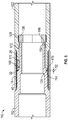
- the tubular connecting arrangement 10 includes a first tubular 12 having a first shoulder 14 and first threads 16 and a second tubular 22 having a second shoulder 24, second threads 26 and third threads 28.
- a seal 32 is sealingly engagable with both the first shoulder 14 and the second shoulder 24.
- an insert 36 is threadably engagable with the third threads 28 and configured to provide at least radial support to the second tubular 22.
- a sleeve 40 is threadably engagable with both the first threads 16 and the second threads 26 in response to being rotated in a same direction relative to both the first tubular 12 and the second tubular 22. This threadable engagement causes the first shoulder 14 and the second shoulder 24 to move toward one another and compress the seal 32 therebetween without requiring the first tubular 12 to rotate relative to the second tubular 22.
- the foregoing structure allows the second tubular 22 to have a minimum inner radial dimension 44 that is larger further from an end portion 48 than nearer to the end portion 48 while still maintaining enough wall thickness of the second tubular 22 near the end portion 48.
- the insert 36 provides structural radial and axial support to the end portion 48 of the second tubular 22 that is needed to prevent damage to the end portion 48 that could occur due to high loads transmitted thereto from the first tubular 12 and imparted thereto from pressure surrounding the second tubular 22. (Of course an alternative approach would be to just make the wall thickness of the second tubular 22 thicker throughout its full length.
- the loads from the first tubular 12 include axially compressive and axially tensive loads due to bending forces applied across the tubular connecting arrangement 10. These axial loads could result in leakage past the seal 32 due to changes in a gap dimension 52 (defined between the two shoulders 14 and 24) and subsequent changes in compression of the seal 32 outside of a desired compression range. Such changes in the compressive loading of the end portion 48 of the second tubular 22 could occur if the insert 36 were not present.
- the insert 36 may include a third shoulder 54 that contacts the first shoulder 14 thereby supporting at least some of the axial load from the first tubular 12 directly.
- the insert 36 allows the minimum inner radial dimension 44 to be as large as a minimum inner radial dimension 56 of the first tubular 12 in areas other than near where the first threads 16 are located.
- tools such as sensor probes, for example, that are generally tubular shaped can be installed into the second tubular 22 prior to engaging the insert 36 into the second tubular 22.
- the tools could have an outer radial dimension that substantially matches the minimum radial dimension 44 and inner radial dimensions that match those of the insert 36.
- the insert 36 includes an optional flange 60 that extends radially outwardly from the rest of the insert 36 and abuts the second shoulder 24 when the insert 36 is fully threadably engaged with the second tubular 22.
- the flange 60 in this embodiment acts as a stop for the threadable engagement of the insert 36 to the second tubular 22.
- the flange 60 can also help prevent a gap dimension 52 between the shoulders 14, 24 from decreasing below a desired minimum dimension.
- the insert 36 can be configured to bottom out with the second threads 26 at a location such that the third shoulder 54 is positioned at the desired location relative to the second tubular 22.
- the insert 36 in the illustrated embodiment also includes an optional noncircular inner portion 64.
- the inner portion 64 is receptive to a tool (not shown) for applying torque to the insert 36 when threadably engaging the insert 36 into the second tubular 22.
- a tool not shown
- the inner portion 64 of the embodiment shown is hexagonal, any noncircular shape including, a square, triangular, pentagonal, oval, star shaped, and octagonal, for example, would suffice.
- FIG. 3 an alternate embodiment of a tubular connecting arrangement disclosed herein is illustrated at 110.
- Components in the arrangement 110 that are similar to components of the arrangement 10 are designated with the same reference characters and are not described again hereunder.
- An insert 136 of the arrangement 110 is threadably engaged within third threads 128 to a position deeper within a second tubular 122 than that of the arrangement 10.
- a third shoulder 154 on the insert 136 is abutted by a fourth shoulder 166 of a first tubular 112 to help carry loads between the first tubular 112 and the second tubular 122.
- tools could be positioned externally to the tubulars 112, 122 to prevent their relative rotation while the sleeve 40 is being threadably engaged therewith.
- An optional fifth shoulder 176 on the either or both of the first tubular 112 or the second tubular 122 contacts a shoulder 114, 124 on the other of the first tubular 112 or the second tubular 122 to help support axially loads between the tubulars 112, 122 and to maintain the gap dimension 52 needed for the seal 32 to maintain sealing integrity.
- FIG. 4 an alternate embodiment of a tubular connecting arrangement disclosed herein is illustrated at 310.
- the arrangement 310 is similar to the arrangement 10 with the major difference being that an insert 336 of the arrangement 310 is threadably engaged within both the third threads 28 of the second tubular 22 and the fourth threads 229 of the first tubular 12.
- the insert 336 includes a flange 360 that defines and helps maintain the gap dimension 52 and sealing integrity of the seal 32 to the first shoulder 14 and the second shoulder 24.
- the seal 32 employed in the embodiments illustrated is "C" shaped and is made of metal, although other embodiment may employ seals made of polymers, elastomers and other materials. Also seals with cross sectional shapes other than "C" shaped may also be employed in embodiments.
- the seal 32 being made of metal at least one of the seal 32, the first shoulder 14 and the second shoulder 24 may be plated with a coating of gold, silver, copper or PTFE. Further at least one of the seal 32, the first shoulder 14 and the second shoulder 24 may have a surface roughness of less than about Ra 1.6. Since metals tend to have higher temperature tolerance than other materials making the seal 32 out of metal may increase temperature as well as pressures at which the arrangements 10, 110, 210, 310 may be used.
- Embodiments disclosed herein allow for maintaining tight tolerances on compressive loading of the seal 32. Additionally, embodiments disclosed herein prevent relative rotational motion between the seal 32 and the shoulders 14, 24 to which it seals to minimize potential damage to the shoulders 14, 24, the seal 32 and any surface coatings or treatments to surfaces of these.
Landscapes
- Engineering & Computer Science (AREA)
- General Engineering & Computer Science (AREA)
- Mechanical Engineering (AREA)
- Physics & Mathematics (AREA)
- Fluid Mechanics (AREA)
- Earth Drilling (AREA)
- Gasket Seals (AREA)
- Mutual Connection Of Rods And Tubes (AREA)
Claims (13)
- Rohrverbindungsanordnung (10), gekennzeichnet durch:ein erstes Rohr (12), aufweisend eine erste Schulter (14) und ein erstes Gewinde (16);ein zweites Rohr (22), aufweisend eine zweite Schulter (24) und ein zweites Gewinde (26), wobei das zweite Rohr (22) eine innere radiale Mindestabmessung (44) aufweist und so eingerichtet ist, dass ein Werkzeug aufgenommen wird, das eine äußere radiale Abmessung aufweist, die in die innere radiale Mindestabmessung (44) des zweiten Rohres (22) passt;eine Dichtung (32), die so ausgelegt ist, dass sie sowohl mit der ersten Schulter (14) als auch mit der zweiten Schulter (24) dichtend in Eingriff gebracht werden kann;einen Einsatz (36), der so ausgelegt ist, dass er mit dem zweiten Rohr (22) gewindemäßig in Eingriff gebracht werden kann und so eingerichtet ist, dass das zweite Rohr (22) radial gestützt wird, wobei die innere radiale Mindestabmessung (44) des zweiten Rohres (22) größer als eine innere radiale Mindestabmessung des Einsatzes (36) ist; undeine Hülse (40), die so ausgelegt ist, dass sie sowohl mit dem ersten Gewinde (16) als auch mit dem zweiten Gewinde (26) in Eingriff gebracht werden kann, wenn sie sowohl in Bezug auf das erste Rohr (12) als auch auf das zweite Rohr (22) in eine gleiche Richtung gedreht wird, sodass die erste Schulter (14) und die zweite Schulter (24) aufeinander zu bewegt werden, um die dazwischen befindliche Dichtung (32) ohne Drehbewegung des ersten Rohres (12) in Bezug auf das zweite Rohr (22) zu komprimieren, wobei die Anordnung (10) so eingerichtet ist, dass ein ausgewähltes Mindestabstandmaß (52) für die Dichtung (32) zwischen der ersten Schulter (14) und der zweiten Schulter (24) eingehalten wird.
- Rohrverbindungsanordnung (10) nach Anspruch 1, wobei der Einsatz (36) eine dritte Schulter (54) umfasst, die so eingerichtet ist, dass die erste Schulter (14) des ersten Rohres (12) berührt wird, um axiale Komprimierungsbeanspruchungen zwischen dem ersten Rohr (12) und dem zweiten Rohr (22) abzustützen.
- Rohrverbindungsanordnung (10) nach Anspruch 2, wobei ein Gewindeeingriff zwischen dem Einsatz (36) und dem zweiten Rohr (22) so eingerichtet ist, dass er so abgesenkt wird, dass sich die dritte Schulter (54) an einer ausgewählten Position relativ zur zweiten Schulter (24) befindet.
- Rohrverbindungsanordnung (10) nach Anspruch 1, wobei der Einsatz (36) eine nicht kreisförmige Innenfläche aufweist, die ein Werkzeug aufnehmen kann, um durch das Werkzeug ein Drehmoment an den Einsatz (36) anzulegen.
- Rohrverbindungsanordnung (10) nach Anspruch 1, wobei der Einsatz (36) einen Flansch (60) beinhaltet, der zwischen der ersten Schulter (14) und der zweiten Schulter (24) komprimiert ist, wenn die Dichtung (32) mit der ersten Schulter (14) und der zweiten Schulter (24) abdichtend in Eingriff steht.
- Rohrverbindungsanordnung (10) nach Anspruch 1, ferner umfassend eine Passfeder (168), die sowohl mit dem ersten Rohr (12) als auch mit dem zweiten Rohr (22) in Eingriff gebracht werden kann, sodass die Passfeder (168) eine relative Drehbewegung zwischen dem ersten Rohr (12) und dem zweiten Rohr (22) verhindert.
- Rohrverbindungsanordnung (10) nach Anspruch 1, wobei die Dichtung (32) aus Metall gefertigt ist.
- Rohrverbindungsanordnung (10) nach Anspruch 7, wobei mindestens entweder die Dichtung (32), die erste Schulter (14) und/oder die zweite Schulter (24) mit einer Beschichtung aus Gold, Silber, Kupfer oder PTFE versehen sind.
- Rohrverbindungsanordnung (10) nach Anspruch 7, wobei mindestens entweder die Dichtung (32), die erste Schulter (14) und/oder die zweite Schulter (24) eine Oberflächenrauigkeit von weniger als Ra 1,6 aufweisen.
- Rohrverbindungsanordnung (10) nach Anspruch 1, wobei das zweite Rohr (22) an seiner Innenseite ein drittes Gewinde (28) aufweist und der Einsatz (36) mit dem dritten Gewinde (28) in Eingriff gebracht werden kann.
- Verfahren zum dichten Verbinden von Rohren, umfassend:Drehen einer Hülse (40), die sowohl mit dem ersten Gewinde (16) eines ersten Rohres (12) als auch mit dem zweiten Gewinde (26) eines zweiten Rohres (22) gewindemäßig in Eingriff steht, wobei das erste Rohr (12) eine erste Schulter (14) und das zweite Rohr (22) eine zweite Schulter (24) aufweist, wobei das zweite Rohr (22) eine innere radiale Mindestabmessung (44) aufweist und so eingerichtet ist, dass ein Werkzeug aufgenommen wird, das eine äußere radiale Abmessung aufweist, die in die innere radiale Mindestabmessung (44) des zweiten Rohres (22) passt, wobei die Hülse (40) in die gleiche Richtung sowohl in Bezug auf das erste Rohr (12) als auch auf das zweite Rohr (22) gedreht wird, sodass die erste Schulter (14) und die zweite Schulter (24) aufeinander zubewegt werden, um eine Dichtung (32) zu komprimieren, die sowohl mit der ersten Schulter (14) als auch mit der zweiten Schulter (24) abdichtend in Eingriff steht, wobei die Anordnung (10) so eingerichtet ist, dass ein ausgewähltes Mindestabstandsmaß (52) für die Dichtung (32) zwischen der ersten Schulter (14) und der zweiten Schulter (24) eingehalten wird;gewindemäßiges Ineingriffbringen eines Einsatzes (36) innerhalb des zweiten Rohres (22), wobei der Einsatz (36) so eingerichtet ist, dass dem zweiten Rohr (22) eine radiale Abstützung bereitgestellt wird, wobei die innere radiale Mindestabmessung (44) des zweiten Rohres (22) größer als eine innere radiale Mindestabmessung des Einsatzes (36) ist;abdichtendes Komprimieren der Dichtung (32) zwischen der ersten Schulter (14) am ersten Rohr (12) und der zweiten Schulter (24) am zweiten Rohr (22) ohne relative Drehung zwischen dem ersten Rohr (12) und dem zweiten Rohr (22); undradiales Abstützen des zweiten Rohres (22) mit dem Einsatz (36).
- Verfahren zum dichten Verbinden von Rohren (12, 22) nach Anspruch 11, ferner umfassend das Absenken des Gewindeeingriffs zwischen dem Einsatz (36) und dem zweiten Rohr (22).
- Verfahren zum dichten Verbinden von Rohren (12, 22) nach Anspruch 11, ferner umfassend ein Anliegen einer dritten Schulter (54) am ersten Rohr (12) am Einsatz (36).
Priority Applications (1)
| Application Number | Priority Date | Filing Date | Title |
|---|---|---|---|
| EP19191155.1A EP3584485B1 (de) | 2014-05-07 | 2015-05-06 | Rohrverbindungsanordnung und verfahren zur dichten verbindung von rohren |
Applications Claiming Priority (2)
| Application Number | Priority Date | Filing Date | Title |
|---|---|---|---|
| US14/271,688 US10066768B2 (en) | 2014-05-07 | 2014-05-07 | Tubular connecting arrangement and method of sealingly connecting tubulars |
| PCT/US2015/029473 WO2015171768A1 (en) | 2014-05-07 | 2015-05-06 | Tubular connecting arrangement and method of sealingly connecting tubulars |
Related Child Applications (2)
| Application Number | Title | Priority Date | Filing Date |
|---|---|---|---|
| EP19191155.1A Division-Into EP3584485B1 (de) | 2014-05-07 | 2015-05-06 | Rohrverbindungsanordnung und verfahren zur dichten verbindung von rohren |
| EP19191155.1A Division EP3584485B1 (de) | 2014-05-07 | 2015-05-06 | Rohrverbindungsanordnung und verfahren zur dichten verbindung von rohren |
Publications (3)
| Publication Number | Publication Date |
|---|---|
| EP3140579A1 EP3140579A1 (de) | 2017-03-15 |
| EP3140579A4 EP3140579A4 (de) | 2017-12-20 |
| EP3140579B1 true EP3140579B1 (de) | 2020-07-01 |
Family
ID=54367477
Family Applications (2)
| Application Number | Title | Priority Date | Filing Date |
|---|---|---|---|
| EP19191155.1A Active EP3584485B1 (de) | 2014-05-07 | 2015-05-06 | Rohrverbindungsanordnung und verfahren zur dichten verbindung von rohren |
| EP15788968.4A Active EP3140579B1 (de) | 2014-05-07 | 2015-05-06 | Rohrverbindungsanordnung und verfahren zum dichten verbinden von rohren |
Family Applications Before (1)
| Application Number | Title | Priority Date | Filing Date |
|---|---|---|---|
| EP19191155.1A Active EP3584485B1 (de) | 2014-05-07 | 2015-05-06 | Rohrverbindungsanordnung und verfahren zur dichten verbindung von rohren |
Country Status (5)
| Country | Link |
|---|---|
| US (2) | US10066768B2 (de) |
| EP (2) | EP3584485B1 (de) |
| CN (1) | CN106489047B (de) |
| BR (1) | BR112016026036B1 (de) |
| WO (1) | WO2015171768A1 (de) |
Families Citing this family (12)
| Publication number | Priority date | Publication date | Assignee | Title |
|---|---|---|---|---|
| US10066768B2 (en) | 2014-05-07 | 2018-09-04 | Baker Hughes, A Ge Company, Llc | Tubular connecting arrangement and method of sealingly connecting tubulars |
| US9893600B2 (en) | 2014-05-09 | 2018-02-13 | Mitsubishi Electric Corporation | Rotating electrical machine and method of mounting element wire temperature measurement sensors on rotating electrical machine |
| CN110651147B (zh) * | 2017-05-22 | 2021-06-01 | 日本制铁株式会社 | 管用螺纹接头及管用螺纹接头的制造方法 |
| US20200190915A1 (en) * | 2018-12-18 | 2020-06-18 | Baker Hughes, A Ge Company, Llc | Guiding sleeve for aligning downhole tubulars |
| CN110617547A (zh) * | 2019-09-11 | 2019-12-27 | 山东智汇新谷科技企业孵化器有限公司 | 一种地环温户空气源热泵机组 |
| CN113389926B (zh) * | 2020-03-12 | 2026-01-02 | 上海盛唐阀门科技股份有限公司 | 一种密封性好的弹簧复位球阀 |
| NO346672B1 (en) * | 2021-02-12 | 2022-11-21 | Fladby Connector As | A pipe coupling |
| CN113700953A (zh) * | 2021-09-18 | 2021-11-26 | 五行科技股份有限公司 | 一种管道连接组件 |
| US20250164152A1 (en) * | 2022-03-15 | 2025-05-22 | Martin Hadlauer | Absorber unit, mirror unit and solar collector or solar installation |
| US20250227834A1 (en) * | 2022-04-12 | 2025-07-10 | Asml Netherlands B.V. | High pressure coupling assembly |
| CN115854138B (zh) * | 2022-12-19 | 2026-01-09 | 珠海格力智能装备有限公司 | 管路连接结构及家用电器 |
| US20250067375A1 (en) * | 2023-08-21 | 2025-02-27 | Robroy Industries - Texas, LLC | Fitting Configured to Connect and Transition into a Conduit Body |
Family Cites Families (44)
| Publication number | Priority date | Publication date | Assignee | Title |
|---|---|---|---|---|
| US236957A (en) | 1881-01-25 | Pipe-coupling | ||
| US1859311A (en) * | 1926-06-01 | 1932-05-24 | Jr Joseph H Mcevoy | Pipe joint |
| US2509363A (en) * | 1948-08-19 | 1950-05-30 | Page Oil Tools Inc | Joint for pipe sections or the like |
| CH482969A (de) | 1967-06-14 | 1969-12-15 | Benteler Werke Ag | Mit Rechts- und Linksgewinde versehene Rohrmuffenverbindung |
| US3479059A (en) * | 1968-07-19 | 1969-11-18 | William B Taylor | Lined pipe sections and joints |
| US3581834A (en) | 1969-07-17 | 1971-06-01 | Smith International | Telescopic drill string unit |
| US3672705A (en) | 1970-06-19 | 1972-06-27 | Garren Corp | Pipe jack |
| AR206593A1 (es) | 1972-03-31 | 1976-08-06 | Kainan Steel Tube Co | Estructura de juntas de acoplamiento para tubos roscados particularmente tuberias para pozos petroliferos |
| US4060264A (en) * | 1976-06-16 | 1977-11-29 | I-T-E Imperial Corporation Efcor Division | Swivel conduit coupling assembly |
| US4434863A (en) | 1979-05-14 | 1984-03-06 | Smith International, Inc. | Drill string splined resilient tubular telescopic joint for balanced load drilling of deep holes |
| DE3207237C2 (de) * | 1982-02-25 | 1984-06-07 | Mannesmann AG, 4000 Düsseldorf | Gewindeverbindung für Ölfeldrohre |
| US4706997A (en) | 1982-05-19 | 1987-11-17 | Carstensen Kenneth J | Coupling for tubing or casing and method of assembly |
| DE3419999C2 (de) | 1984-05-29 | 1987-02-12 | Karl 7298 Loßburg Hehl | Rohrverschraubung mit Berührungsdichtung |
| US4694859A (en) | 1985-11-25 | 1987-09-22 | National Coupling Company, Inc. | Undersea hydraulic coupling and metal seal |
| GB2222785B (en) * | 1988-09-17 | 1992-02-12 | Usui Kokusai Sangyo Kk | Multi-layered pipe coating |
| US6070912A (en) | 1989-08-01 | 2000-06-06 | Reflange, Inc. | Dual seal and connection |
| US5104151A (en) * | 1991-05-15 | 1992-04-14 | Adams Don L | Coupler apparatus for connecting a conduit to an equipment opening having damaged threads |
| US5415442A (en) | 1992-03-09 | 1995-05-16 | Marubeni Tubulars, Inc. | Stabilized center-shoulder-sealed tubular connection |
| JP3081094B2 (ja) | 1993-10-15 | 2000-08-28 | トヨタ自動車株式会社 | 半導体レーザ及びその製造方法 |
| US6425829B1 (en) | 1994-12-06 | 2002-07-30 | Nitinol Technologies, Inc. | Threaded load transferring attachment |
| WO1996029533A1 (en) | 1995-03-23 | 1996-09-26 | Hydril Company | Threaded pipe connection |
| US6568501B2 (en) * | 1998-03-11 | 2003-05-27 | Paulsson Geophysical Services, Inc. | Receiver array using tubing conveyed packer elements |
| FR2803363B1 (fr) * | 2000-01-05 | 2002-07-12 | Vetrotex France Sa | Dispositif de raccordement pour deux tuyaux en materiau composite a base de matiere thermoplastique |
| CN2421486Y (zh) * | 2000-03-30 | 2001-02-28 | 罗众名 | 下水管活接 |
| US6666275B2 (en) | 2001-08-02 | 2003-12-23 | Halliburton Energy Services, Inc. | Bridge plug |
| US7431351B2 (en) | 2002-04-26 | 2008-10-07 | Russell Larry R | Pressure-containing tubular connections for remote operation |
| US7347459B2 (en) * | 2004-04-30 | 2008-03-25 | Gb Tubulars, Inc. | Coupling for drilling-with-casing operations |
| WO2005108844A2 (en) | 2004-05-05 | 2005-11-17 | Huston Fred N | Threaded connection for oil field applications |
| US7438329B2 (en) | 2005-01-11 | 2008-10-21 | V&M Atlas Bradford, Lp | Methods and connections for coupled pipe |
| US7434848B2 (en) * | 2005-05-12 | 2008-10-14 | Boyd Anthony R | Threaded tubular connection having interlocking tubular end structures |
| US20060267342A1 (en) * | 2005-05-12 | 2006-11-30 | Boyd Anthony R | Tubular connection and method |
| FR2895485B1 (fr) | 2005-12-23 | 2012-04-13 | Vallourec Mannesmann Oil & Gas | Protection externe de joints filetes tubulaires aptes a etre expanses |
| WO2009003016A1 (en) | 2007-06-26 | 2008-12-31 | Swagelok Company | Conduit connection with sensing function |
| US8136604B2 (en) | 2009-03-13 | 2012-03-20 | Vetco Gray Inc. | Wireline run fracture isolation sleeve and plug and method of operating same |
| EP2243920A1 (de) | 2009-04-22 | 2010-10-27 | Tenaris Connections Aktiengesellschaft | Gewindeverbindung für Röhren, Leitungen und dergleichen |
| EP2354603A1 (de) * | 2010-02-09 | 2011-08-10 | Carl Freudenberg KG | Abdichtung zwischen einem feststehenden Maschinenteil und einem um dieses drehenden zweiten Maschinenteil |
| US8251139B2 (en) | 2010-02-25 | 2012-08-28 | Carstensen Kenneth J | System and method for sealing couplings in downhole tubing strings |
| US10215314B2 (en) * | 2010-08-23 | 2019-02-26 | Vallourec Oil And Gas France | Tubular threaded connection |
| WO2014013989A1 (ja) * | 2012-07-17 | 2014-01-23 | ダイキン工業株式会社 | 継手類用雌型部材 |
| JP5783146B2 (ja) * | 2012-08-08 | 2015-09-24 | 新日鐵住金株式会社 | 鋼管用ねじ継手 |
| CN203215127U (zh) * | 2013-04-16 | 2013-09-25 | 天津商业大学 | 用于两种不同材质管材间的可拆卸密封连接装置 |
| CN203297790U (zh) * | 2013-06-04 | 2013-11-20 | 无锡金顶石油管材配件制造有限公司 | 一种膨胀圈式管端连接件 |
| CN203348771U (zh) * | 2013-07-05 | 2013-12-18 | 合肥安诺新型建材有限公司 | 一种踢脚线散热器连接装置 |
| US10066768B2 (en) | 2014-05-07 | 2018-09-04 | Baker Hughes, A Ge Company, Llc | Tubular connecting arrangement and method of sealingly connecting tubulars |
-
2014
- 2014-05-07 US US14/271,688 patent/US10066768B2/en active Active
-
2015
- 2015-05-06 CN CN201580023970.6A patent/CN106489047B/zh active Active
- 2015-05-06 EP EP19191155.1A patent/EP3584485B1/de active Active
- 2015-05-06 WO PCT/US2015/029473 patent/WO2015171768A1/en not_active Ceased
- 2015-05-06 BR BR112016026036-8A patent/BR112016026036B1/pt active IP Right Grant
- 2015-05-06 EP EP15788968.4A patent/EP3140579B1/de active Active
-
2018
- 2018-08-01 US US16/052,296 patent/US10753517B2/en active Active
Non-Patent Citations (1)
| Title |
|---|
| None * |
Also Published As
| Publication number | Publication date |
|---|---|
| CN106489047B (zh) | 2020-02-18 |
| US20150323108A1 (en) | 2015-11-12 |
| CN106489047A (zh) | 2017-03-08 |
| US10753517B2 (en) | 2020-08-25 |
| EP3140579A1 (de) | 2017-03-15 |
| US20180340636A1 (en) | 2018-11-29 |
| US10066768B2 (en) | 2018-09-04 |
| EP3584485B1 (de) | 2021-11-10 |
| BR112016026036B1 (pt) | 2021-07-20 |
| EP3584485A1 (de) | 2019-12-25 |
| WO2015171768A1 (en) | 2015-11-12 |
| EP3140579A4 (de) | 2017-12-20 |
Similar Documents
| Publication | Publication Date | Title |
|---|---|---|
| EP3140579B1 (de) | Rohrverbindungsanordnung und verfahren zum dichten verbinden von rohren | |
| EP2372208B1 (de) | Gewindeverbindung mit elastomerischem Dichtflansch | |
| US6254147B1 (en) | Fluid-tight connecting apparatus | |
| MY140837A (en) | Liquid- and gas-tight threaded tubular connection | |
| US8727315B2 (en) | Ball valve | |
| KR20190104641A (ko) | 페룰을 갖는 푸시 접속 도관 피팅 | |
| RU2722195C2 (ru) | Трубчатый элемент с винтовым упором | |
| US12553546B2 (en) | Fluid fitting | |
| US6565093B2 (en) | Seal structure for downhole tool | |
| CN107531274B (zh) | 活塞组件 | |
| US9850732B2 (en) | Seal assembly for a downhole device | |
| US20130043657A1 (en) | S-seal | |
| EP3141789A2 (de) | Nutzlastrohrkugelgelenk | |
| NO20151379A1 (en) | Improved Seal Assembly | |
| EP2643598B1 (de) | Sicherungsring | |
| EP3096059A1 (de) | Drehkupplung | |
| US10443769B2 (en) | Pivot joint | |
| US9777874B2 (en) | Rotary coupling | |
| EP3842680B1 (de) | Schraubverbindung für stahlrohre | |
| US9377138B2 (en) | Threaded connections and methods | |
| US10006256B2 (en) | Safety joint designed with anti-lock pressure compensation seal | |
| WO2014038954A1 (en) | Seal assembly and seal ring | |
| US20120160572A1 (en) | Vibration-Resistant Seal for Downhole Tool |
Legal Events
| Date | Code | Title | Description |
|---|---|---|---|
| STAA | Information on the status of an ep patent application or granted ep patent |
Free format text: STATUS: THE INTERNATIONAL PUBLICATION HAS BEEN MADE |
|
| PUAI | Public reference made under article 153(3) epc to a published international application that has entered the european phase |
Free format text: ORIGINAL CODE: 0009012 |
|
| STAA | Information on the status of an ep patent application or granted ep patent |
Free format text: STATUS: REQUEST FOR EXAMINATION WAS MADE |
|
| 17P | Request for examination filed |
Effective date: 20161130 |
|
| AK | Designated contracting states |
Kind code of ref document: A1 Designated state(s): AL AT BE BG CH CY CZ DE DK EE ES FI FR GB GR HR HU IE IS IT LI LT LU LV MC MK MT NL NO PL PT RO RS SE SI SK SM TR |
|
| AX | Request for extension of the european patent |
Extension state: BA ME |
|
| RIN1 | Information on inventor provided before grant (corrected) |
Inventor name: HERBEL, ANDREAS Inventor name: HAUBOLD, CARSTEN Inventor name: MUELLER, STEPHAN |
|
| DAV | Request for validation of the european patent (deleted) | ||
| DAX | Request for extension of the european patent (deleted) | ||
| REG | Reference to a national code |
Ref country code: DE Ref legal event code: R079 Ref document number: 602015055139 Country of ref document: DE Free format text: PREVIOUS MAIN CLASS: F16L0015040000 Ipc: F16L0015000000 |
|
| A4 | Supplementary search report drawn up and despatched |
Effective date: 20171121 |
|
| RIC1 | Information provided on ipc code assigned before grant |
Ipc: F16L 15/04 20060101ALI20171115BHEP Ipc: F16L 15/08 20060101ALI20171115BHEP Ipc: F16L 17/08 20060101ALI20171115BHEP Ipc: F16L 15/02 20060101ALI20171115BHEP Ipc: F16L 15/00 20060101AFI20171115BHEP |
|
| STAA | Information on the status of an ep patent application or granted ep patent |
Free format text: STATUS: EXAMINATION IS IN PROGRESS |
|
| 17Q | First examination report despatched |
Effective date: 20181022 |
|
| RAP1 | Party data changed (applicant data changed or rights of an application transferred) |
Owner name: BAKER HUGHES, A GE COMPANY, LLC |
|
| GRAP | Despatch of communication of intention to grant a patent |
Free format text: ORIGINAL CODE: EPIDOSNIGR1 |
|
| STAA | Information on the status of an ep patent application or granted ep patent |
Free format text: STATUS: GRANT OF PATENT IS INTENDED |
|
| INTG | Intention to grant announced |
Effective date: 20191022 |
|
| GRAJ | Information related to disapproval of communication of intention to grant by the applicant or resumption of examination proceedings by the epo deleted |
Free format text: ORIGINAL CODE: EPIDOSDIGR1 |
|
| STAA | Information on the status of an ep patent application or granted ep patent |
Free format text: STATUS: EXAMINATION IS IN PROGRESS |
|
| GRAP | Despatch of communication of intention to grant a patent |
Free format text: ORIGINAL CODE: EPIDOSNIGR1 |
|
| STAA | Information on the status of an ep patent application or granted ep patent |
Free format text: STATUS: GRANT OF PATENT IS INTENDED |
|
| INTC | Intention to grant announced (deleted) | ||
| INTG | Intention to grant announced |
Effective date: 20191212 |
|
| GRAS | Grant fee paid |
Free format text: ORIGINAL CODE: EPIDOSNIGR3 |
|
| GRAA | (expected) grant |
Free format text: ORIGINAL CODE: 0009210 |
|
| STAA | Information on the status of an ep patent application or granted ep patent |
Free format text: STATUS: THE PATENT HAS BEEN GRANTED |
|
| AK | Designated contracting states |
Kind code of ref document: B1 Designated state(s): AL AT BE BG CH CY CZ DE DK EE ES FI FR GB GR HR HU IE IS IT LI LT LU LV MC MK MT NL NO PL PT RO RS SE SI SK SM TR |
|
| REG | Reference to a national code |
Ref country code: CH Ref legal event code: EP Ref country code: AT Ref legal event code: REF Ref document number: 1286507 Country of ref document: AT Kind code of ref document: T Effective date: 20200715 |
|
| REG | Reference to a national code |
Ref country code: IE Ref legal event code: FG4D |
|
| REG | Reference to a national code |
Ref country code: DE Ref legal event code: R096 Ref document number: 602015055139 Country of ref document: DE |
|
| REG | Reference to a national code |
Ref country code: NO Ref legal event code: T2 Effective date: 20200701 |
|
| REG | Reference to a national code |
Ref country code: LT Ref legal event code: MG4D |
|
| PG25 | Lapsed in a contracting state [announced via postgrant information from national office to epo] |
Ref country code: BG Free format text: LAPSE BECAUSE OF FAILURE TO SUBMIT A TRANSLATION OF THE DESCRIPTION OR TO PAY THE FEE WITHIN THE PRESCRIBED TIME-LIMIT Effective date: 20201001 |
|
| REG | Reference to a national code |
Ref country code: NL Ref legal event code: MP Effective date: 20200701 |
|
| REG | Reference to a national code |
Ref country code: AT Ref legal event code: MK05 Ref document number: 1286507 Country of ref document: AT Kind code of ref document: T Effective date: 20200701 |
|
| PG25 | Lapsed in a contracting state [announced via postgrant information from national office to epo] |
Ref country code: FI Free format text: LAPSE BECAUSE OF FAILURE TO SUBMIT A TRANSLATION OF THE DESCRIPTION OR TO PAY THE FEE WITHIN THE PRESCRIBED TIME-LIMIT Effective date: 20200701 Ref country code: CZ Free format text: LAPSE BECAUSE OF FAILURE TO SUBMIT A TRANSLATION OF THE DESCRIPTION OR TO PAY THE FEE WITHIN THE PRESCRIBED TIME-LIMIT Effective date: 20200701 Ref country code: LT Free format text: LAPSE BECAUSE OF FAILURE TO SUBMIT A TRANSLATION OF THE DESCRIPTION OR TO PAY THE FEE WITHIN THE PRESCRIBED TIME-LIMIT Effective date: 20200701 Ref country code: HR Free format text: LAPSE BECAUSE OF FAILURE TO SUBMIT A TRANSLATION OF THE DESCRIPTION OR TO PAY THE FEE WITHIN THE PRESCRIBED TIME-LIMIT Effective date: 20200701 Ref country code: ES Free format text: LAPSE BECAUSE OF FAILURE TO SUBMIT A TRANSLATION OF THE DESCRIPTION OR TO PAY THE FEE WITHIN THE PRESCRIBED TIME-LIMIT Effective date: 20200701 Ref country code: GR Free format text: LAPSE BECAUSE OF FAILURE TO SUBMIT A TRANSLATION OF THE DESCRIPTION OR TO PAY THE FEE WITHIN THE PRESCRIBED TIME-LIMIT Effective date: 20201002 Ref country code: SE Free format text: LAPSE BECAUSE OF FAILURE TO SUBMIT A TRANSLATION OF THE DESCRIPTION OR TO PAY THE FEE WITHIN THE PRESCRIBED TIME-LIMIT Effective date: 20200701 Ref country code: PT Free format text: LAPSE BECAUSE OF FAILURE TO SUBMIT A TRANSLATION OF THE DESCRIPTION OR TO PAY THE FEE WITHIN THE PRESCRIBED TIME-LIMIT Effective date: 20201102 Ref country code: AT Free format text: LAPSE BECAUSE OF FAILURE TO SUBMIT A TRANSLATION OF THE DESCRIPTION OR TO PAY THE FEE WITHIN THE PRESCRIBED TIME-LIMIT Effective date: 20200701 |
|
| PG25 | Lapsed in a contracting state [announced via postgrant information from national office to epo] |
Ref country code: PL Free format text: LAPSE BECAUSE OF FAILURE TO SUBMIT A TRANSLATION OF THE DESCRIPTION OR TO PAY THE FEE WITHIN THE PRESCRIBED TIME-LIMIT Effective date: 20200701 Ref country code: RS Free format text: LAPSE BECAUSE OF FAILURE TO SUBMIT A TRANSLATION OF THE DESCRIPTION OR TO PAY THE FEE WITHIN THE PRESCRIBED TIME-LIMIT Effective date: 20200701 Ref country code: LV Free format text: LAPSE BECAUSE OF FAILURE TO SUBMIT A TRANSLATION OF THE DESCRIPTION OR TO PAY THE FEE WITHIN THE PRESCRIBED TIME-LIMIT Effective date: 20200701 Ref country code: IS Free format text: LAPSE BECAUSE OF FAILURE TO SUBMIT A TRANSLATION OF THE DESCRIPTION OR TO PAY THE FEE WITHIN THE PRESCRIBED TIME-LIMIT Effective date: 20201101 |
|
| PG25 | Lapsed in a contracting state [announced via postgrant information from national office to epo] |
Ref country code: NL Free format text: LAPSE BECAUSE OF FAILURE TO SUBMIT A TRANSLATION OF THE DESCRIPTION OR TO PAY THE FEE WITHIN THE PRESCRIBED TIME-LIMIT Effective date: 20200701 |
|
| REG | Reference to a national code |
Ref country code: DE Ref legal event code: R097 Ref document number: 602015055139 Country of ref document: DE |
|
| PG25 | Lapsed in a contracting state [announced via postgrant information from national office to epo] |
Ref country code: RO Free format text: LAPSE BECAUSE OF FAILURE TO SUBMIT A TRANSLATION OF THE DESCRIPTION OR TO PAY THE FEE WITHIN THE PRESCRIBED TIME-LIMIT Effective date: 20200701 Ref country code: SM Free format text: LAPSE BECAUSE OF FAILURE TO SUBMIT A TRANSLATION OF THE DESCRIPTION OR TO PAY THE FEE WITHIN THE PRESCRIBED TIME-LIMIT Effective date: 20200701 Ref country code: EE Free format text: LAPSE BECAUSE OF FAILURE TO SUBMIT A TRANSLATION OF THE DESCRIPTION OR TO PAY THE FEE WITHIN THE PRESCRIBED TIME-LIMIT Effective date: 20200701 Ref country code: DK Free format text: LAPSE BECAUSE OF FAILURE TO SUBMIT A TRANSLATION OF THE DESCRIPTION OR TO PAY THE FEE WITHIN THE PRESCRIBED TIME-LIMIT Effective date: 20200701 Ref country code: IT Free format text: LAPSE BECAUSE OF FAILURE TO SUBMIT A TRANSLATION OF THE DESCRIPTION OR TO PAY THE FEE WITHIN THE PRESCRIBED TIME-LIMIT Effective date: 20200701 |
|
| PLBE | No opposition filed within time limit |
Free format text: ORIGINAL CODE: 0009261 |
|
| STAA | Information on the status of an ep patent application or granted ep patent |
Free format text: STATUS: NO OPPOSITION FILED WITHIN TIME LIMIT |
|
| PG25 | Lapsed in a contracting state [announced via postgrant information from national office to epo] |
Ref country code: AL Free format text: LAPSE BECAUSE OF FAILURE TO SUBMIT A TRANSLATION OF THE DESCRIPTION OR TO PAY THE FEE WITHIN THE PRESCRIBED TIME-LIMIT Effective date: 20200701 |
|
| 26N | No opposition filed |
Effective date: 20210406 |
|
| PG25 | Lapsed in a contracting state [announced via postgrant information from national office to epo] |
Ref country code: SK Free format text: LAPSE BECAUSE OF FAILURE TO SUBMIT A TRANSLATION OF THE DESCRIPTION OR TO PAY THE FEE WITHIN THE PRESCRIBED TIME-LIMIT Effective date: 20200701 |
|
| PG25 | Lapsed in a contracting state [announced via postgrant information from national office to epo] |
Ref country code: SI Free format text: LAPSE BECAUSE OF FAILURE TO SUBMIT A TRANSLATION OF THE DESCRIPTION OR TO PAY THE FEE WITHIN THE PRESCRIBED TIME-LIMIT Effective date: 20200701 |
|
| REG | Reference to a national code |
Ref country code: DE Ref legal event code: R119 Ref document number: 602015055139 Country of ref document: DE |
|
| REG | Reference to a national code |
Ref country code: CH Ref legal event code: PL |
|
| PG25 | Lapsed in a contracting state [announced via postgrant information from national office to epo] |
Ref country code: MC Free format text: LAPSE BECAUSE OF FAILURE TO SUBMIT A TRANSLATION OF THE DESCRIPTION OR TO PAY THE FEE WITHIN THE PRESCRIBED TIME-LIMIT Effective date: 20200701 Ref country code: LU Free format text: LAPSE BECAUSE OF NON-PAYMENT OF DUE FEES Effective date: 20210506 Ref country code: LI Free format text: LAPSE BECAUSE OF NON-PAYMENT OF DUE FEES Effective date: 20210531 Ref country code: CH Free format text: LAPSE BECAUSE OF NON-PAYMENT OF DUE FEES Effective date: 20210531 |
|
| REG | Reference to a national code |
Ref country code: BE Ref legal event code: MM Effective date: 20210531 |
|
| PG25 | Lapsed in a contracting state [announced via postgrant information from national office to epo] |
Ref country code: IE Free format text: LAPSE BECAUSE OF NON-PAYMENT OF DUE FEES Effective date: 20210506 Ref country code: DE Free format text: LAPSE BECAUSE OF NON-PAYMENT OF DUE FEES Effective date: 20211201 |
|
| PG25 | Lapsed in a contracting state [announced via postgrant information from national office to epo] |
Ref country code: FR Free format text: LAPSE BECAUSE OF NON-PAYMENT OF DUE FEES Effective date: 20210531 |
|
| PG25 | Lapsed in a contracting state [announced via postgrant information from national office to epo] |
Ref country code: BE Free format text: LAPSE BECAUSE OF NON-PAYMENT OF DUE FEES Effective date: 20210531 |
|
| PG25 | Lapsed in a contracting state [announced via postgrant information from national office to epo] |
Ref country code: HU Free format text: LAPSE BECAUSE OF FAILURE TO SUBMIT A TRANSLATION OF THE DESCRIPTION OR TO PAY THE FEE WITHIN THE PRESCRIBED TIME-LIMIT; INVALID AB INITIO Effective date: 20150506 |
|
| PG25 | Lapsed in a contracting state [announced via postgrant information from national office to epo] |
Ref country code: CY Free format text: LAPSE BECAUSE OF FAILURE TO SUBMIT A TRANSLATION OF THE DESCRIPTION OR TO PAY THE FEE WITHIN THE PRESCRIBED TIME-LIMIT Effective date: 20200701 |
|
| P01 | Opt-out of the competence of the unified patent court (upc) registered |
Effective date: 20230526 |
|
| PG25 | Lapsed in a contracting state [announced via postgrant information from national office to epo] |
Ref country code: MK Free format text: LAPSE BECAUSE OF FAILURE TO SUBMIT A TRANSLATION OF THE DESCRIPTION OR TO PAY THE FEE WITHIN THE PRESCRIBED TIME-LIMIT Effective date: 20200701 |
|
| PG25 | Lapsed in a contracting state [announced via postgrant information from national office to epo] |
Ref country code: TR Free format text: LAPSE BECAUSE OF FAILURE TO SUBMIT A TRANSLATION OF THE DESCRIPTION OR TO PAY THE FEE WITHIN THE PRESCRIBED TIME-LIMIT Effective date: 20200701 |
|
| PG25 | Lapsed in a contracting state [announced via postgrant information from national office to epo] |
Ref country code: MT Free format text: LAPSE BECAUSE OF FAILURE TO SUBMIT A TRANSLATION OF THE DESCRIPTION OR TO PAY THE FEE WITHIN THE PRESCRIBED TIME-LIMIT Effective date: 20200701 |
|
| PGFP | Annual fee paid to national office [announced via postgrant information from national office to epo] |
Ref country code: GB Payment date: 20250423 Year of fee payment: 11 |
|
| PGFP | Annual fee paid to national office [announced via postgrant information from national office to epo] |
Ref country code: NO Payment date: 20250424 Year of fee payment: 11 |