EP3141789A2 - Nutzlastrohrkugelgelenk - Google Patents
Nutzlastrohrkugelgelenk Download PDFInfo
- Publication number
- EP3141789A2 EP3141789A2 EP16001947.7A EP16001947A EP3141789A2 EP 3141789 A2 EP3141789 A2 EP 3141789A2 EP 16001947 A EP16001947 A EP 16001947A EP 3141789 A2 EP3141789 A2 EP 3141789A2
- Authority
- EP
- European Patent Office
- Prior art keywords
- spring
- pipe
- ball joint
- casing
- joint according
- Prior art date
- Legal status (The legal status is an assumption and is not a legal conclusion. Google has not performed a legal analysis and makes no representation as to the accuracy of the status listed.)
- Withdrawn
Links
- 238000012856 packing Methods 0.000 claims description 10
- 238000000034 method Methods 0.000 description 4
- 238000007789 sealing Methods 0.000 description 4
- 238000012423 maintenance Methods 0.000 description 2
- 239000010426 asphalt Substances 0.000 description 1
- 238000004891 communication Methods 0.000 description 1
- 230000008878 coupling Effects 0.000 description 1
- 238000010168 coupling process Methods 0.000 description 1
- 238000005859 coupling reaction Methods 0.000 description 1
- 238000013461 design Methods 0.000 description 1
- 238000005516 engineering process Methods 0.000 description 1
- 238000004519 manufacturing process Methods 0.000 description 1
- 238000012986 modification Methods 0.000 description 1
- 230000004048 modification Effects 0.000 description 1
Images
Classifications
-
- F—MECHANICAL ENGINEERING; LIGHTING; HEATING; WEAPONS; BLASTING
- F16—ENGINEERING ELEMENTS AND UNITS; GENERAL MEASURES FOR PRODUCING AND MAINTAINING EFFECTIVE FUNCTIONING OF MACHINES OR INSTALLATIONS; THERMAL INSULATION IN GENERAL
- F16L—PIPES; JOINTS OR FITTINGS FOR PIPES; SUPPORTS FOR PIPES, CABLES OR PROTECTIVE TUBING; MEANS FOR THERMAL INSULATION IN GENERAL
- F16L27/00—Adjustable joints; Joints allowing movement
- F16L27/02—Universal joints, i.e. with mechanical connection allowing angular movement or adjustment of the axes of the parts in any direction
- F16L27/04—Universal joints, i.e. with mechanical connection allowing angular movement or adjustment of the axes of the parts in any direction with partly-spherical engaging surfaces
- F16L27/06—Universal joints, i.e. with mechanical connection allowing angular movement or adjustment of the axes of the parts in any direction with partly-spherical engaging surfaces with special sealing means between the engaging surfaces
-
- F—MECHANICAL ENGINEERING; LIGHTING; HEATING; WEAPONS; BLASTING
- F16—ENGINEERING ELEMENTS AND UNITS; GENERAL MEASURES FOR PRODUCING AND MAINTAINING EFFECTIVE FUNCTIONING OF MACHINES OR INSTALLATIONS; THERMAL INSULATION IN GENERAL
- F16L—PIPES; JOINTS OR FITTINGS FOR PIPES; SUPPORTS FOR PIPES, CABLES OR PROTECTIVE TUBING; MEANS FOR THERMAL INSULATION IN GENERAL
- F16L27/00—Adjustable joints; Joints allowing movement
- F16L27/02—Universal joints, i.e. with mechanical connection allowing angular movement or adjustment of the axes of the parts in any direction
- F16L27/04—Universal joints, i.e. with mechanical connection allowing angular movement or adjustment of the axes of the parts in any direction with partly-spherical engaging surfaces
-
- F—MECHANICAL ENGINEERING; LIGHTING; HEATING; WEAPONS; BLASTING
- F16—ENGINEERING ELEMENTS AND UNITS; GENERAL MEASURES FOR PRODUCING AND MAINTAINING EFFECTIVE FUNCTIONING OF MACHINES OR INSTALLATIONS; THERMAL INSULATION IN GENERAL
- F16L—PIPES; JOINTS OR FITTINGS FOR PIPES; SUPPORTS FOR PIPES, CABLES OR PROTECTIVE TUBING; MEANS FOR THERMAL INSULATION IN GENERAL
- F16L27/00—Adjustable joints; Joints allowing movement
- F16L27/02—Universal joints, i.e. with mechanical connection allowing angular movement or adjustment of the axes of the parts in any direction
- F16L27/04—Universal joints, i.e. with mechanical connection allowing angular movement or adjustment of the axes of the parts in any direction with partly-spherical engaging surfaces
- F16L27/053—Universal joints, i.e. with mechanical connection allowing angular movement or adjustment of the axes of the parts in any direction with partly-spherical engaging surfaces held in place by bolts passing through flanges
-
- F—MECHANICAL ENGINEERING; LIGHTING; HEATING; WEAPONS; BLASTING
- F16—ENGINEERING ELEMENTS AND UNITS; GENERAL MEASURES FOR PRODUCING AND MAINTAINING EFFECTIVE FUNCTIONING OF MACHINES OR INSTALLATIONS; THERMAL INSULATION IN GENERAL
- F16L—PIPES; JOINTS OR FITTINGS FOR PIPES; SUPPORTS FOR PIPES, CABLES OR PROTECTIVE TUBING; MEANS FOR THERMAL INSULATION IN GENERAL
- F16L27/00—Adjustable joints; Joints allowing movement
- F16L27/02—Universal joints, i.e. with mechanical connection allowing angular movement or adjustment of the axes of the parts in any direction
- F16L27/04—Universal joints, i.e. with mechanical connection allowing angular movement or adjustment of the axes of the parts in any direction with partly-spherical engaging surfaces
- F16L27/06—Universal joints, i.e. with mechanical connection allowing angular movement or adjustment of the axes of the parts in any direction with partly-spherical engaging surfaces with special sealing means between the engaging surfaces
- F16L27/073—Universal joints, i.e. with mechanical connection allowing angular movement or adjustment of the axes of the parts in any direction with partly-spherical engaging surfaces with special sealing means between the engaging surfaces one of the cooperating surfaces forming the sealing means
Definitions
- the present disclosure relates to a ball joint pipe coupling for connecting misaligned pipes in fluid-tight communication.
- the present disclosure provides a live loaded ball pipe joint design which accommodates for seal decay without the need for maintenance or adjustment.
- the live load pipe ball joint includes a casing having a socket portion with a substantially spherical interior surface and a first pipe segment extending from the socket portion.
- the socket portion has an annular groove disposed adjacent the partially spherical interior surface.
- a ball pipe section includes a ball segment received in the socket portion of the casing and a second pipe segment extending from the ball segment.
- a seal is received in the annular groove of the casing and is disposed against the ball segment of the ball pipe section.
- a push ring is disposed against the seal and a spring is disposed against the push ring.
- a retainer is secured to the casing encompassing the ball pipe, and is disposed against the spring for loading the spring against the push ring.
- the loaded spring accommodates for decay of the sealing components and automatically adjusts the position of the push ring as the sealing components decay.
- Example embodiments are provided so that this disclosure will be thorough, and will fully convey the scope to those who are skilled in the art. Numerous specific details are set forth such as examples of specific components, devices, and methods, to provide a thorough understanding of embodiments of the present disclosure. It will be apparent to those skilled in the art that specific details need not be employed, that example embodiments may be embodied in many different forms and that neither should be construed to limit the scope of the disclosure. In some example embodiments, well-known processes, well-known device structures, and well-known technologies are not described in detail.
- spatially relative terms such as “inner,” “outer,” “beneath,” “below,” “lower,” “above,” “upper,” and the like, may be used herein for ease of description to describe one element or feature's relationship to another element(s) or feature(s) as illustrated in the figures.
- Spatially relative terms may be intended to encompass different orientations of the device in use or operation in addition to the orientation depicted in the figures. For example, if the device in the figures is turned over, elements described as “below” or “beneath” other elements or features would then be oriented “above” the other elements or features.
- the example term “below” can encompass both an orientation of above and below.
- the device may be otherwise oriented (rotated 90 degrees or at other orientations) and the spatially relative descriptors used herein interpreted accordingly.
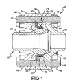
- the live load pipe ball joint 10 includes a casing 12 having a socket portion14 and a pipe segment 16 extending from the socket portion 14.
- the socket portion 14 has an interior surface portion 18 that is substantially spherical.
- the socket portion 14 also includes an annular groove 20 disposed adjacent the substantially spherical interior surface portion 18.
- a ball pipe section 22 includes a substantially spherical ball-shaped segment 24 which is received in the partially spherical interior surface portion 18 of the socket portion 14 and a pipe segment 26 extending from the ball-shape segment 24.
- a seal 28 is received in the annular groove 20 of the socket portion 14 and is disposed against the ball-shaped segment 24 of the ball pipe section 22.
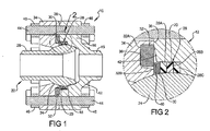
- the seal 28 can include a packing of multiple seal elements 28A-C, as best shown in Figure 2 .
- a push ring 30 is disposed against the seal 28.
- One or more springs 32 are disposed against the push ring 30 and a retainer 34 is secured to the casing 12 and disposed against the spring 32 for loading the spring 32 against the push ring 30 and retains the ball pipe section within the socket portion 14.
- the spring(s) 32 is (are) preferably a Belleville spring although other springs such as helical springs can also be utilized.
- the retainer 34 can include an annular groove 36 disposed in a face 38 that opposes the casing 12. The spring 32 can be received in the annular groove 36. In the embodiment shown, a radially outer portion 32A of the Belleville spring 32 is disposed against a bottom of the annular groove 36 of the retainer 34 and a radially inner portion 32B of the Belleville spring 32 is disposed against the push ring 30.
- the retainer 34 can also include a rest surface 40 radially inward of the annular groove 36. The rest surface 40 can oppose the push ring 30.
- the casing 12 can also include a relief surface 42 disposed radially outward of the annular groove 20 of the casing 12 and opposing the spring 32.
- the relief surface 42 can be tapered to accommodate the unloading of the flattened out Belleville spring 32 as it expands to accommodate for decay of the seal 28 over time.
- the live load pipe ball joint 10 is assembled by placing the seal 28 within the casing 12.
- the ball pipe section 22 is then inserted into the casing 12 and the push ring 30 is placed on top of the seal packing 28.
- the retainer 34 and Belleville spring 32 are then installed on top and the entire assembly is pressed together in a hydraulic press.
- Retainer 34 is secured to the casing 12 and a plurality of studs 44 and nuts 46 are installed and torqued to specified values.
- the press provides enough force to form the packing 28 around the ball-shape segment 24. As the seal packing 28 is formed, it becomes more dense. The seal 28 compresses to a point until it is dense enough to be stronger than the Belleville spring 32.
- the seal 28 no longer compresses and it is instead the Belleville spring 32 that begins loading.
- the Belleville spring 32 should be designed for the specific packing and to provide a load which creates a stored energy that is later used when the packing wears or consolidates. Accordingly, the unloading of the Belleville spring 32 accommodates for the wear of the packing over time so that no additional maintenance or adjustment is necessary.
Landscapes
- Engineering & Computer Science (AREA)
- General Engineering & Computer Science (AREA)
- Mechanical Engineering (AREA)
- Joints Allowing Movement (AREA)
- Quick-Acting Or Multi-Walled Pipe Joints (AREA)
Applications Claiming Priority (1)
| Application Number | Priority Date | Filing Date | Title |
|---|---|---|---|
| US14/850,169 US20170074439A1 (en) | 2015-09-10 | 2015-09-10 | Live load pipe ball joint |
Publications (2)
| Publication Number | Publication Date |
|---|---|
| EP3141789A2 true EP3141789A2 (de) | 2017-03-15 |
| EP3141789A3 EP3141789A3 (de) | 2017-04-26 |
Family
ID=56888892
Family Applications (1)
| Application Number | Title | Priority Date | Filing Date |
|---|---|---|---|
| EP16001947.7A Withdrawn EP3141789A3 (de) | 2015-09-10 | 2016-09-07 | Nutzlastrohrkugelgelenk |
Country Status (3)
| Country | Link |
|---|---|
| US (1) | US20170074439A1 (de) |
| EP (1) | EP3141789A3 (de) |
| CA (1) | CA2929406C (de) |
Cited By (1)
| Publication number | Priority date | Publication date | Assignee | Title |
|---|---|---|---|---|
| WO2021194625A1 (en) * | 2020-03-23 | 2021-09-30 | Freudenberg Oil & Gas, Llc | Ball joint seal |
Families Citing this family (3)
| Publication number | Priority date | Publication date | Assignee | Title |
|---|---|---|---|---|
| GB2578326B (en) * | 2018-10-24 | 2020-12-16 | John Guest International Ltd | A coaxial connector comprising a ball joint |
| CA3170916A1 (en) * | 2019-11-12 | 2020-02-12 | Gary Arthur Stroud | Offset-alignment pivotable coupler fittings for sealably interconnecting high-pressure lines |
| US11619104B2 (en) * | 2020-10-08 | 2023-04-04 | Halliburton Energy Services, Inc. | Shape memory alloy shaft alignment coupler for downhole tools |
Family Cites Families (7)
| Publication number | Priority date | Publication date | Assignee | Title |
|---|---|---|---|---|
| US978876A (en) * | 1910-03-19 | 1910-12-20 | Greenlaw Mfg Company | Flexible pipe-joint. |
| US1015435A (en) * | 1911-01-25 | 1912-01-23 | Greenlaw Mfg Co | Train-pipe connection. |
| GB218449A (en) * | 1923-05-25 | 1924-07-10 | Evered & Co Ltd | Improvements relating to ball and socket joints for pipe connections |
| US2550536A (en) * | 1947-06-19 | 1951-04-24 | Franklin Railway Supply Co | High-pressure ball and socket pipe joint |
| GB1031133A (en) * | 1964-05-27 | 1966-05-25 | J R H Products & Company Ltd | Pipe couplings |
| GB1072466A (en) * | 1965-06-14 | 1967-06-14 | J R H Products & Company Ltd | Pipe couplings |
| US3951418A (en) * | 1974-01-21 | 1976-04-20 | W. S. Shamban & Co. | Moving captive seal construction usable under high temperature and cryogenic conditions |
-
2015
- 2015-09-10 US US14/850,169 patent/US20170074439A1/en not_active Abandoned
-
2016
- 2016-05-09 CA CA2929406A patent/CA2929406C/en not_active Expired - Fee Related
- 2016-09-07 EP EP16001947.7A patent/EP3141789A3/de not_active Withdrawn
Non-Patent Citations (1)
| Title |
|---|
| None |
Cited By (2)
| Publication number | Priority date | Publication date | Assignee | Title |
|---|---|---|---|---|
| WO2021194625A1 (en) * | 2020-03-23 | 2021-09-30 | Freudenberg Oil & Gas, Llc | Ball joint seal |
| US11549623B2 (en) | 2020-03-23 | 2023-01-10 | Freudenberg Oil & Gas, Llc | Ball joint seal |
Also Published As
| Publication number | Publication date |
|---|---|
| US20170074439A1 (en) | 2017-03-16 |
| CA2929406A1 (en) | 2017-03-10 |
| CA2929406C (en) | 2018-07-31 |
| EP3141789A3 (de) | 2017-04-26 |
Similar Documents
| Publication | Publication Date | Title |
|---|---|---|
| US11549623B2 (en) | Ball joint seal | |
| CA2929406C (en) | Live load pipe ball joint | |
| US6923476B2 (en) | Floating seal for undersea hydraulic coupling | |
| EP3584485B1 (de) | Rohrverbindungsanordnung und verfahren zur dichten verbindung von rohren | |
| US8702056B2 (en) | Plug valve and stem sealing assembly | |
| USRE47010E1 (en) | Valve and stem sealing assembly | |
| MXPA05002247A (es) | Junta roscada tubular impermeable con respecto al medio exterior. | |
| US9239114B2 (en) | Compressable sealing ring assembly | |
| US4153281A (en) | Misalignment connector with retained internal spherical seal | |
| US20180363645A1 (en) | Valve Adapter Connection Assembly | |
| EP2584229A1 (de) | O-Ringabschirmungssystem und Verfahren | |
| US7604056B2 (en) | Downhole valve and method of making | |
| US20130106093A1 (en) | Misalignment Connector Utilizing Interleaved Bearings | |
| EP3491275B1 (de) | Absperrdichtung für hochtemperatur- druckausgleichsventil und zugehörige verfahren | |
| US11408544B2 (en) | Fluid coupling | |
| US9377138B2 (en) | Threaded connections and methods | |
| EP1947376A2 (de) | Hermetisches Kühlmittelteil | |
| EP3338017B1 (de) | Flexible rohrverbindung | |
| EP2971448B1 (de) | Fluidleitungsverbindungssystem | |
| CN117628265A (zh) | 阀填料设备和相关方法 |
Legal Events
| Date | Code | Title | Description |
|---|---|---|---|
| PUAI | Public reference made under article 153(3) epc to a published international application that has entered the european phase |
Free format text: ORIGINAL CODE: 0009012 |
|
| AK | Designated contracting states |
Kind code of ref document: A2 Designated state(s): AL AT BE BG CH CY CZ DE DK EE ES FI FR GB GR HR HU IE IS IT LI LT LU LV MC MK MT NL NO PL PT RO RS SE SI SK SM TR |
|
| AX | Request for extension of the european patent |
Extension state: BA ME |
|
| PUAL | Search report despatched |
Free format text: ORIGINAL CODE: 0009013 |
|
| AK | Designated contracting states |
Kind code of ref document: A3 Designated state(s): AL AT BE BG CH CY CZ DE DK EE ES FI FR GB GR HR HU IE IS IT LI LT LU LV MC MK MT NL NO PL PT RO RS SE SI SK SM TR |
|
| AX | Request for extension of the european patent |
Extension state: BA ME |
|
| RIC1 | Information provided on ipc code assigned before grant |
Ipc: F16L 27/04 20060101AFI20170322BHEP Ipc: F16L 27/073 20060101ALI20170322BHEP Ipc: F16L 27/053 20060101ALI20170322BHEP Ipc: F16L 27/06 20060101ALI20170322BHEP |
|
| 17P | Request for examination filed |
Effective date: 20170804 |
|
| RBV | Designated contracting states (corrected) |
Designated state(s): AL AT BE BG CH CY CZ DE DK EE ES FI FR GB GR HR HU IE IS IT LI LT LU LV MC MK MT NL NO PL PT RO RS SE SI SK SM TR |
|
| GRAP | Despatch of communication of intention to grant a patent |
Free format text: ORIGINAL CODE: EPIDOSNIGR1 |
|
| INTG | Intention to grant announced |
Effective date: 20171116 |
|
| GRAS | Grant fee paid |
Free format text: ORIGINAL CODE: EPIDOSNIGR3 |
|
| GRAL | Information related to payment of fee for publishing/printing deleted |
Free format text: ORIGINAL CODE: EPIDOSDIGR3 |
|
| GRAS | Grant fee paid |
Free format text: ORIGINAL CODE: EPIDOSNIGR3 |
|
| STAA | Information on the status of an ep patent application or granted ep patent |
Free format text: STATUS: THE APPLICATION IS DEEMED TO BE WITHDRAWN |
|
| GRAL | Information related to payment of fee for publishing/printing deleted |
Free format text: ORIGINAL CODE: EPIDOSDIGR3 |
|
| 18D | Application deemed to be withdrawn |
Effective date: 20180327 |