EP3140596B1 - Vertical grill with external drip tray module - Google Patents
Vertical grill with external drip tray module Download PDFInfo
- Publication number
- EP3140596B1 EP3140596B1 EP14885295.7A EP14885295A EP3140596B1 EP 3140596 B1 EP3140596 B1 EP 3140596B1 EP 14885295 A EP14885295 A EP 14885295A EP 3140596 B1 EP3140596 B1 EP 3140596B1
- Authority
- EP
- European Patent Office
- Prior art keywords
- tray
- slide
- module
- grill
- drip tray
- Prior art date
- Legal status (The legal status is an assumption and is not a legal conclusion. Google has not performed a legal analysis and makes no representation as to the accuracy of the status listed.)
- Active
Links
Images


Classifications
-
- A—HUMAN NECESSITIES
- A47—FURNITURE; DOMESTIC ARTICLES OR APPLIANCES; COFFEE MILLS; SPICE MILLS; SUCTION CLEANERS IN GENERAL
- A47J—KITCHEN EQUIPMENT; COFFEE MILLS; SPICE MILLS; APPARATUS FOR MAKING BEVERAGES
- A47J37/00—Baking; Roasting; Grilling; Frying
- A47J37/06—Roasters; Grills; Sandwich grills
- A47J37/07—Roasting devices for outdoor use; Barbecues
- A47J37/0718—Roasting devices for outdoor use; Barbecues with vertical fire box
-
- A—HUMAN NECESSITIES
- A47—FURNITURE; DOMESTIC ARTICLES OR APPLIANCES; COFFEE MILLS; SPICE MILLS; SUCTION CLEANERS IN GENERAL
- A47J—KITCHEN EQUIPMENT; COFFEE MILLS; SPICE MILLS; APPARATUS FOR MAKING BEVERAGES
- A47J37/00—Baking; Roasting; Grilling; Frying
- A47J37/06—Roasters; Grills; Sandwich grills
- A47J37/0623—Small-size cooking ovens, i.e. defining an at least partially closed cooking cavity
- A47J37/0664—Accessories
-
- A—HUMAN NECESSITIES
- A47—FURNITURE; DOMESTIC ARTICLES OR APPLIANCES; COFFEE MILLS; SPICE MILLS; SUCTION CLEANERS IN GENERAL
- A47J—KITCHEN EQUIPMENT; COFFEE MILLS; SPICE MILLS; APPARATUS FOR MAKING BEVERAGES
- A47J37/00—Baking; Roasting; Grilling; Frying
- A47J37/06—Roasters; Grills; Sandwich grills
- A47J37/067—Horizontally disposed broiling griddles
- A47J37/0676—Horizontally disposed broiling griddles electrically heated
-
- A—HUMAN NECESSITIES
- A47—FURNITURE; DOMESTIC ARTICLES OR APPLIANCES; COFFEE MILLS; SPICE MILLS; SUCTION CLEANERS IN GENERAL
- A47J—KITCHEN EQUIPMENT; COFFEE MILLS; SPICE MILLS; APPARATUS FOR MAKING BEVERAGES
- A47J37/00—Baking; Roasting; Grilling; Frying
- A47J37/06—Roasters; Grills; Sandwich grills
- A47J37/0688—Broilers with vertically disposed heat sources and food supports
-
- A—HUMAN NECESSITIES
- A47—FURNITURE; DOMESTIC ARTICLES OR APPLIANCES; COFFEE MILLS; SPICE MILLS; SUCTION CLEANERS IN GENERAL
- A47J—KITCHEN EQUIPMENT; COFFEE MILLS; SPICE MILLS; APPARATUS FOR MAKING BEVERAGES
- A47J37/00—Baking; Roasting; Grilling; Frying
- A47J37/06—Roasters; Grills; Sandwich grills
- A47J37/07—Roasting devices for outdoor use; Barbecues
- A47J37/0754—Roasting devices for outdoor use; Barbecues with blowers providing forced air circulation
-
- A—HUMAN NECESSITIES
- A47—FURNITURE; DOMESTIC ARTICLES OR APPLIANCES; COFFEE MILLS; SPICE MILLS; SUCTION CLEANERS IN GENERAL
- A47J—KITCHEN EQUIPMENT; COFFEE MILLS; SPICE MILLS; APPARATUS FOR MAKING BEVERAGES
- A47J37/00—Baking; Roasting; Grilling; Frying
- A47J37/06—Roasters; Grills; Sandwich grills
- A47J37/07—Roasting devices for outdoor use; Barbecues
- A47J37/0786—Accessories
-
- A—HUMAN NECESSITIES
- A47—FURNITURE; DOMESTIC ARTICLES OR APPLIANCES; COFFEE MILLS; SPICE MILLS; SUCTION CLEANERS IN GENERAL
- A47J—KITCHEN EQUIPMENT; COFFEE MILLS; SPICE MILLS; APPARATUS FOR MAKING BEVERAGES
- A47J37/00—Baking; Roasting; Grilling; Frying
- A47J37/06—Roasters; Grills; Sandwich grills
- A47J37/08—Bread-toasters
- A47J37/0807—Bread-toasters with radiating heaters and reflectors
-
- A—HUMAN NECESSITIES
- A47—FURNITURE; DOMESTIC ARTICLES OR APPLIANCES; COFFEE MILLS; SPICE MILLS; SUCTION CLEANERS IN GENERAL
- A47J—KITCHEN EQUIPMENT; COFFEE MILLS; SPICE MILLS; APPARATUS FOR MAKING BEVERAGES
- A47J37/00—Baking; Roasting; Grilling; Frying
- A47J37/06—Roasters; Grills; Sandwich grills
- A47J37/08—Bread-toasters
- A47J37/0871—Accessories
-
- F—MECHANICAL ENGINEERING; LIGHTING; HEATING; WEAPONS; BLASTING
- F24—HEATING; RANGES; VENTILATING
- F24C—DOMESTIC STOVES OR RANGES ; DETAILS OF DOMESTIC STOVES OR RANGES, OF GENERAL APPLICATION
- F24C15/00—Details
- F24C15/006—Arrangements for circulation of cooling air
Definitions
- This invention relates to cooking appliances for use in domestic and commercial kitchens.
- the invention relates particularly to electric grills that can be used to cook food in a way that removes fat from the food that is cooked.
- the invention relates to a vertical electric grill and a removable slide and tray module for directing fats and breakaway solids from the inside of the grill to the tray's exterior receptacle for safe storage and cooling during the cooking process.
- AHA American Heart Association
- Grills in which the radiant cooking elements and grilling space have been arranged vertically are particularly well adapted to cook the food on both sides simultaneously and to remove fats from meat that is being cooked. As the food is suspended between the cooking elements gravity and pressure of a holding clasp act to separate liquefied fats and oils from the food such that the liquefied fats and oils drip out of and away from the food being cooked.
- Vertical grills have been recommended by heart physicians as a suitable device to help patients and the public reduce their intake of saturated fats that would otherwise be ingested with conventionally cooked meats.
- prior art vertical grills used an internal drip tray to collect and retain combustible fats, oils, and waste solids that fall from the food being grilled between two radiant cooking elements.
- internal drip tray to collect and retain combustible fats, oils, and waste solids that fall from the food being grilled between two radiant cooking elements.
- the prior art vertical grills with an internal drip tray are prone to fire flare-ups and smoke
- US 3 742 838 A discloses a vertical grill with a fat slide and a fat slide.
- US 7 339 137 B1 discloses a horizontal grill with a slide and a drip tray.
- WO 2011/103621 A1 discloses another vertical grill with a slide and a drip receptacle at the end of the slide.
- An aspect of some embodiments of the present invention relates to a removable slide and drip tray module with external receptacle for use in a grill.
- the drip tray of the present invention includes a slide which guides the separated hot, liquified fats and breakaway solids (all of which form a group which will be herein called "discarded waste") generated by the grilling of the food to the external collection receptacle positioned at the lowest point of the module for cooling and disposal outside the body of the grill.
- the drip tray includes one or more channels configured for enabling passage of air therethrough and enabling the airflow to contact the slide. In this manner, the discarded waste of the grilled food is cooled while they are located inside the grill and as they slide toward the external receptacle.
- a drip tray module for a grill is configured to catch fats and break away solids generated during the cooking process.
- the tray comprises a front side, back side, bottom side, and left and right sides.
- a slide is positioned at an incline between the front and back sides, configured to direct fats and break away solids away from back side to the front side of the tray. At least one channel for air flow covered by the slide.
- An external receptacle is positioned at the front side of the tray, wherein the slide leads into the receptacle so that fats and break away solids may be channeled into the external receptacle after traveling downwards along the incline of the slide.
- the module comprises floor members in the channels; and the sides of the tray form an air space underneath the tray that allows for air flow from below the tray and into channels formed below the slide via apertures in the floor members of the channels.
- the slide comprises two surfaces leading to a middle surface and disposed on either side of the middle surface and are angled higher than the middle the surface.
- the tray module further comprises a step in the left and right sides to receive a recessed bottom panel of the grill, and hang over the edge of the bottom panel of the grill, when the tray is inserted into the grill.
- the drip tray module further comprises a plurality of ribs defining a plurality of channels, supporting the slide and maintaining a gap between the floor of the channels and the slide to provide air channels under the slide which enable air to flow through openings in a front end and of the channels out of openings in the back end of the channels.
- the back end of the channels are on the back side of the drip tray module.
- the module is formed from a bottom tray and the slide, the slide being removable from the bottom tray.
- the module is formed from a bottom tray and the slide.
- the tray module further comprises a gap formed near the front of the tray module between the slide and the bottom tray, wherein lateral side panels of the slide are of sufficient length to create the gap between the slide and the bottom tray to allow air to flow into the gap.
- the drip tray module comprises at least one opening in either the left or right side of the tray.
- the drip tray module of claim 1 wherein the slide is formed from a heat conductive material to enable heat exchange between the air flowing below the plate and the discarded waste sliding on the plate.
- the plate is made of metal and the drip tray module includes magnets configured to attach the metal plate to the tray module.
- An aspect of some embodiments of the present invention is directed toward an external drip tray for a vertical grill.
- Fig 1 is an isometric view of a grease tray assembly generally designated as numeral 1.
- Fig. 7 is a right side view of the tray assembly and
- Fig. 8 is a sectional view of the tray assembly.
- the tray assembly is configured to catch the discarded waste dripping from food inside the vertical grill during cooking and to channel the discarded waste (fats, grease and break away solids) from inside the grill to an external receptacle component 7.
- Fig. 2 is a top view of a slide 2 which is part of the tray of the present invention
- Fig. 3 is a front view of the slide 2.
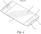
- Fig. 4 is an isometric drawing of slide 2.
- Fig. 8 is a sectional view of the grease tray assembly.
- the grease tray assembly 1 includes a top plate/slide 2 and a bottom tray 3.
- the slide 2 covers the bottom tray 3.
- the bottom tray 3 may be a one piece molded plastic base.
- the bottom tray 3 is made of a fireproof material.
- the slide 2 is inclined downward toward the external receptacle component 7, so as to lead the discarded waste to the external receptacle component. In a non-limiting example, the inclination of the slide 2 is approximately 15 degrees.
- the inclination angle in the present invention can be low since the cooling effect of the panel 2 enables to discarded waste to slowly travel along the panel without reaching flashpoint temperatures (the flash point temperature being the temperature above which the discarded waste catches fire or smokes). Having a low inclination is particularly advantageous for keeping the profile of the vertical grill low. A higher temperature within the vertical grill would require the inclination angle to be increased to accelerate the draining of the discarded waste to the outside tray receptacle before flash point temperature is reached.
- the slide 2 includes lateral side surfaces 4, 5, and a middle surface 6 located between the side surfaces.
- the side surface 4 and 5 are slanted toward the middle of slide 2 to drain grease from the sides to the middle surface 6.
- an external receptacle component 7 At the front of bottom molded tray 3 is an external receptacle component 7.
- the external receptacle component 7 may be removably attached to the tray.
- a tray handle 8 is located on the front of the external receptacle component 7, to ease the tray's insertion to and removal from the grill.
- the slide 2 includes at least one slot (optionally two slots 10, 11) on at least one lateral side of the slide 2.
- the slot(s) is (are) configured for mating with corresponding holding button(s) 13.
- an identical slot/button arrangement is provided for each of the two lateral sides of the tray assembly. The slot/button arrangement enables the slide 2 to be removably joined to bottom molded tray 3, so that the slide 2 can be easily removed for cleaning.
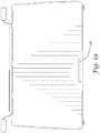
- FIG. 5 , 8 , and 20 there is provided an isometric drawing illustrating a bottom tray 3 with the top metal slide 2 removed. Lateral ends 14 along with ribs 16 support the slide 2 and maintain a gap between the floor of the bottom tray and slide 2.
- floor members 25, in conjunction with the slide 2 provide air tunnels 18 (as shown in Fig. 8 ) under slide 2. Cool air comes in through end opening 9 then flows up through apertures 12 in the floor members and on in direction of air flow arrow 29, through the tunnels to the back of the tray. The cool air cools the slide 2 and thus keeps the discarded waste below flash point temperature.
- the slide 2 is made of a heat conductive material to enable heat exchange between the air flowing below the slide and the discarded waste sliding on the slide 2, thus facilitating the cooling of the discarded waste.
- the slide 2 is made of metal
- the tray assembly 1 comprises magnets at least one magnet 105 attached at least one lateral end 14 for securing the metal slide to the tray assembly 1.
- Fig. 9 is a front cross section
- Fig. 10 is a lateral cross section
- Fig. 14 is a top view of the vertical grill.
- the vertical grill assembly includes a back chimney 39 bounded by a back frame 38 and a back cover 40.
- the vertical grill includes a front chimney 60 bounded by a front frame member 57 and a front cover. In either chimney, a chimney effect causes air be drawn into the chimney's bottom, rise up through the chimney, and exit the vertical grill assembly via an exit vent located at the top of the vertical grill assembly.
- the back frame member 38 includes a plurality of openings (33-37). These openings enable passage of air from the tray to be back chimney 39.
- a front opening is provided between the lowermost point of the grill's front cover and the uppermost point of the grease tray, to enable passage of air 41 from outside. A first portion of the air 41 rises through the front chimney 60. A second portion of the air travels along the top surface of the slide 2 and enters the back chimney 39.
- Fig. 8 it can be seen that the tray 1 rests against the back frame member 38.
- the slide 2 divides the opening 35 in half.
- the air traveling through the tunnel 18 enters the back chimney 39 via the lower half of opening 35.
- a chimney effect drafts this air to the top of the grill and ejects the air outward.
- the air flows in direction of arrow 41 into the top half of the opening 35 and upward through the back chimney 39.
- the discarded waste are cooled by the air entering though the bottom opening 9 (by heat exchange with via the slide 2) and by air entering though the vertical grill's front opening (by direct contact between the air and the discarded waste).
- the air entering though the tray's bottom opening 9 flows into the grill via a side opening, and/or a bottom opening, and/or or a front opening on the grill, which is (are) at least partially aligned with the bottom opening 9. This cooling effect lowers the risk of fire.
- the vertical grill includes a cooking basket 50 for cooking food in the middle of the grill, surrounded by four Cal Rods 51, 52, 53 & 54 which generate heat.
- Removable heat shields 55 & 56 are installed behind the Cal Rods, so that the Cal Rods are located between a corresponding removable shield and the cooking basket 50.
- the removable heat shields are concave, in order to reflect heat back to the food basket.
- the vertical grill assembly includes an inner metal frame comprising a back frame member 38, front metal frame member 57, left end frame 58 and right end frame member (not shown).
- Figs. 11-13 illustrate removable side heat shields located inside the vertical grill.
- a removable heat shield optionally includes surfaces 31 and 32, which are inclined downward to catch the discarded waste dripping and/or dropping from the cooking basket 50 and drains the discarded waste to the tray assembly 1. This allows the cooking basket to be wider than the grease tray.
- openings 33, 34, 35, 36 and 37 are openings 33, 34, 35, 36 and 37. These openings permit air flow from inside the grill assembly to the space 39 between the outside back cover 40 and the back inner frame wall 38.
- the vertical grill with external drip tray module 1 has an opening 115 in the back of the tray and corresponding similarly shaped vent holes 110 for aligning with the opening 115 of the tray in the inner and outer walls of the grill.
- the opening 110 together with the vent holes 115 provide additional cooling airflow through the vertical grill with external drip tray module 1.
- the region between the vent holes 110 and is separated from the back chimney by a wall 120. This separation prevents air entering the vertical grill via the vent holes 110 from traveling within the back chimney. In this manner, air entering via the vent holes 110 continues through the vent hole 115, external drip tray module 1 and follows the path in the air tunnels 18 to cool the top slide 2.
- Fig. 21 is an isometric view of a top plate/slide with elongated side panels, according to some embodiments of the present invention.
- Fig. 22 is a right side view of the grease tray assembly illustrating air flow via a gap between the floor members of the bottom tray and the plate or slide which has elongated side panels.
- each side panel 130 of top plate 2 includes one or more slots (e.g., the slots 10 and 11) configured for mating with corresponding holding buttons 13 located on the side of the bottom tray. Because the side panels are elongated, a gap 125 is formed on the front of the tray assembly 1, between the top plate 2 and the bottom tray when the top plate is joined to the bottom tray. In this manner, air may enter tray assembly via the gap 125, travel in the region between the top plate and the bottom tray to cool the top plate 2, and enter the back chimney, before being expelled via the air exits.
- FIG. 22 In the example of Fig. 22 , four air intakes are shown, for drawing outside air to cool the top plate 2: (i) the front opening above the plate 2, (ii) the bottom opening 9 of the bottom tray, (iii) the intake formed by the openings 110 and 115, and (iv) the gap 125.
- the present invention extends to all embodiments in which any one of these intakes is present, to embodiments in which any subset of these intakes is present, and to the embodiments in which all four intakes are present.
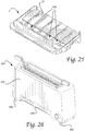
- Figs. 23-25 are perspective drawings illustrating a tray assembly of the present invention, in which an air intake opening is present on its bottom side.
- the module 1 of the embodiments of Figs. 23-25 includes a tray 3 and a plate 2.
- the plate is similar to the plate described in above.
- the tray 3 includes two lateral panels 150, at least one of which includes an extension 152 extending downward.
- the tray 3 also includes one or more legs 154 configured for elevating the external receptacle component 7 above a surface upon which the tray is placed.
- the legs may be, for example joined to the bottom panel of the external receptacle component 7.
- the legs 154 may also be in the form of extensions from the lateral panels 150.
- the in the tray 3, the floor members 25 include openings 156. In this manner, air may flow from outside through the gap between the external receptacle component 7 and the surface on which the tray is located, and through the openings 156, to cool off the tray, as will be explained further in this document.
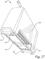
- Figs. 26 and 27 are perspective drawings illustrating a grill of the present invention, in which the base is receded with respect to the front panel.
- the grill 200 includes a plurality of legs 202 joined to the bottom of the grill and keeping the grill elevated with respect to a surface upon which the grill is located.
- the four legs are present.
- the grill 200 includes a bottom panel 204 which is receded with respect to the front panel 206.
- the receded bottom panel 204 is configured for coming into contact with the extension 152 of the tray module 1 and for stopping the tray module 1.
- the grill 200 when the tray module 1 of Figs. 23-25 is inserted into the grill 200, air may flow from under the external receptacle component 7 to the apertures 156, and along the path between the floor members 25 and the tray, to cool down the tray.
- Figs. 28 and 29 are drawings illustrating the drip tray module of Figs. 23-25 inserted into the grill of Figs. 26-27 .
- the extension 152 of the tray module 1 engages the bottom panel 204 of the grill 200 and prevents the tray module from being further inserted into the grill.
- the legs 202 keep the grill elevated, while the legs 154 keep the tray module elevated. In this manner, an air flow 210 is created, which passes under the tray module's external receptacle component 7, through the openings 156, and into the space between the floor members 25 and slide/plate 2.
- a group of items linked with the conjunction "and” should not be read as requiring that each and every one of those items be present in the grouping, but rather should be read as “and/or” unless expressly stated otherwise.
- a group of items linked with the conjunction "or” should not be read as requiring mutual exclusivity among that group, but rather should also be read as “and/or” unless expressly stated otherwise.
- items, elements or components of the invention may be described or claimed in the singular, the plural is contemplated to be within the scope thereof unless limitation to the singular is explicitly stated.
- module does not imply that the components or functionality described or claimed as part of the module are all configured in a common package. Indeed, any or all of the various components of a module, whether control logic or other components, can be combined in a single package or separately maintained and can further be distributed across multiple locations.
Landscapes
- Engineering & Computer Science (AREA)
- Food Science & Technology (AREA)
- Mechanical Engineering (AREA)
- Chemical & Material Sciences (AREA)
- Combustion & Propulsion (AREA)
- General Engineering & Computer Science (AREA)
- Baking, Grill, Roasting (AREA)
- Ceramic Engineering (AREA)
Priority Applications (1)
| Application Number | Priority Date | Filing Date | Title |
|---|---|---|---|
| PL14885295T PL3140596T3 (pl) | 2014-03-11 | 2014-10-09 | Grill pionowy z modułem zewnętrznej tacy ociekowej |
Applications Claiming Priority (3)
| Application Number | Priority Date | Filing Date | Title |
|---|---|---|---|
| US201461951516P | 2014-03-11 | 2014-03-11 | |
| US14/493,348 US9883770B2 (en) | 2014-03-11 | 2014-09-23 | Vertical grill with external drip tray module |
| PCT/US2014/059942 WO2015138007A1 (en) | 2014-03-11 | 2014-10-09 | Vertical grill with external drip tray module |
Publications (3)
| Publication Number | Publication Date |
|---|---|
| EP3140596A1 EP3140596A1 (en) | 2017-03-15 |
| EP3140596A4 EP3140596A4 (en) | 2018-06-13 |
| EP3140596B1 true EP3140596B1 (en) | 2019-09-18 |
Family
ID=54067575
Family Applications (1)
| Application Number | Title | Priority Date | Filing Date |
|---|---|---|---|
| EP14885295.7A Active EP3140596B1 (en) | 2014-03-11 | 2014-10-09 | Vertical grill with external drip tray module |
Country Status (14)
| Country | Link |
|---|---|
| US (3) | US9883770B2 (da) |
| EP (1) | EP3140596B1 (da) |
| JP (1) | JP6688532B2 (da) |
| KR (1) | KR102306328B1 (da) |
| CN (1) | CN106662335B (da) |
| AU (6) | AU2014386260A1 (da) |
| BR (1) | BR112016020945B1 (da) |
| CA (1) | CA2942333A1 (da) |
| DK (1) | DK3140596T3 (da) |
| ES (1) | ES2773286T3 (da) |
| MX (1) | MX2016011710A (da) |
| PL (1) | PL3140596T3 (da) |
| PT (1) | PT3140596T (da) |
| WO (1) | WO2015138007A1 (da) |
Cited By (1)
| Publication number | Priority date | Publication date | Assignee | Title |
|---|---|---|---|---|
| US11882961B1 (en) | 2023-01-18 | 2024-01-30 | Sharkninja Operating Llc | Cover plate for cooking devices |
Families Citing this family (27)
| Publication number | Priority date | Publication date | Assignee | Title |
|---|---|---|---|---|
| WO2017044619A1 (en) * | 2015-09-09 | 2017-03-16 | Traeger Pellet Grills, Llc | Internal chimney system for grills and smokers |
| KR200487062Y1 (ko) * | 2016-08-12 | 2018-07-31 | 주식회사 파세코 | 수직그릴 조리기 |
| IT201800004549A1 (it) * | 2018-04-16 | 2019-10-16 | Dispositivo di cottura e metodo, particolarmente per la cottura di un pezzo di carne | |
| CN212346260U (zh) | 2019-02-26 | 2021-01-15 | 沙克忍者运营有限责任公司 | 能够在支承表面上定位的烹饪系统和能够安装的烹饪系统 |
| USD935272S1 (en) | 2019-03-14 | 2021-11-09 | Edwin Peterson | Rack for a smoker |
| KR102235630B1 (ko) * | 2020-04-06 | 2021-04-05 | 주식회사 이씨엠 | 공냉식 숯불구이기 |
| US12593937B2 (en) * | 2020-07-10 | 2026-04-07 | Hamilton Beach Brands, Inc. | Multi-functional oven with air fryer capability |
| US11812895B2 (en) | 2020-08-04 | 2023-11-14 | The Grease Box Llc | Grease containment systems |
| FI131051B1 (fi) * | 2020-11-13 | 2024-08-19 | Kesko Oyj | Rasvapelti |
| US12318038B2 (en) | 2020-12-02 | 2025-06-03 | Weber-Stephen Products Llc | Slidable waste management systems for cookboxes of grills |
| KR102423909B1 (ko) * | 2021-11-09 | 2022-07-21 | 드라이스팀 주식회사 | 수직형 조리 시스템 |
| US12502033B2 (en) | 2021-11-12 | 2025-12-23 | Sharkninja Operating Llc | Cooking systems with improved heating consistency |
| USD1032279S1 (en) | 2022-03-29 | 2024-06-25 | Sharkninja Operating Llc | Outdoor grill |
| US12478213B2 (en) | 2022-03-29 | 2025-11-25 | Sharkninja Operating Llc | Grill system with smoke assembly |
| US12446730B2 (en) | 2022-03-29 | 2025-10-21 | Sharkninja Operating Llc | Grill system with smoke assembly |
| US11732895B1 (en) | 2022-05-16 | 2023-08-22 | Sharkninja Operating Llc | Methods and systems for open-loop ignition of a smoke generator fuel source |
| USD974837S1 (en) * | 2022-06-08 | 2023-01-10 | Xiaoying CUI | Barbeque oil drop collector |
| CN217659391U (zh) * | 2022-06-27 | 2022-10-28 | 宁波吉盛电器有限公司 | 一种烤炉用炉壳结构 |
| CN218921514U (zh) * | 2022-10-13 | 2023-04-28 | 宁波吉盛电器有限公司 | 一种电烟熏炉 |
| US12035725B2 (en) | 2022-12-12 | 2024-07-16 | Sharkninja Operating, Llc | Grill systems |
| US12070042B2 (en) | 2022-12-12 | 2024-08-27 | Sharkninja Operating Llc | Grill systems |
| USD988075S1 (en) * | 2023-02-01 | 2023-06-06 | Shenzhen Yuanchi Zhichuang Technology Co., Ltd. | Grill grease tray |
| US11849884B1 (en) | 2023-06-01 | 2023-12-26 | Sharkninja Operating Llc | Methods and systems for ignition of a smoke unit fuel source |
| US11792895B1 (en) | 2023-06-01 | 2023-10-17 | Sharkninja Operating Llc | Methods and systems for TRIAC set point based control of power delivery |
| USD1063487S1 (en) | 2023-06-07 | 2025-02-25 | Sharkninja Operating Llc | Countertop grill |
| USD1063483S1 (en) | 2023-06-15 | 2025-02-25 | Sharkninja Operating Llc | Cooking device |
| KR102562856B1 (ko) * | 2023-06-21 | 2023-08-02 | 주식회사 에스티 | 소형 세로형 오븐 |
Family Cites Families (21)
| Publication number | Priority date | Publication date | Assignee | Title |
|---|---|---|---|---|
| US917195A (en) * | 1906-05-28 | 1909-04-06 | Gen Electric | Electric oven. |
| US3324788A (en) * | 1964-12-28 | 1967-06-13 | France Hazel M La | Barbecue construction |
| US3742838A (en) * | 1971-11-01 | 1973-07-03 | R Piccony | Vertical grill device |
| US4034663A (en) * | 1974-08-19 | 1977-07-12 | Jenn Air Corporation | Ventilated portable electric grill |
| US3971308A (en) * | 1975-07-21 | 1976-07-27 | Parker Darrell G | Portable smokehouse |
| US4119021A (en) * | 1977-04-25 | 1978-10-10 | Viola M. Heyward | Gas stove attachment |
| FR2495425A1 (fr) * | 1980-12-01 | 1982-06-04 | Moulinex Sa | Gril electrique pour aliments |
| US4574770A (en) * | 1984-08-14 | 1986-03-11 | Roger Wells | Cooking grill grease catcher |
| US4862795A (en) * | 1988-06-06 | 1989-09-05 | General Electric Company | Cooktop grill with improved reflector pan |
| US4979436A (en) * | 1989-01-23 | 1990-12-25 | Mcgowan Michael J | Smoking and baking apparatus |
| JPH04180719A (ja) * | 1990-11-14 | 1992-06-26 | Matsushita Electric Ind Co Ltd | グリラー |
| US5603256A (en) * | 1993-08-13 | 1997-02-18 | The Thermos Company | Barbecue grill |
| ES2125614T3 (es) * | 1994-05-05 | 1999-03-01 | Ernst Gschwind | Dispositivo para cocinar alimentos. |
| US5890422A (en) * | 1996-06-24 | 1999-04-06 | Grill-N-Roast, Inc. | Convertible drip pan and method of using the same |
| JPH1078227A (ja) * | 1996-09-03 | 1998-03-24 | Paloma Ind Ltd | ガスグリル |
| WO2000011995A1 (de) * | 1998-08-28 | 2000-03-09 | Ernst Gschwind | Vorrichtung zur zubereitung von speisen |
| US6237472B1 (en) * | 1999-12-13 | 2001-05-29 | Richard L. Gates | Drip collector |
| JP2001190423A (ja) * | 2000-01-07 | 2001-07-17 | Rinnai Corp | グリル |
| US7339137B1 (en) * | 2004-10-07 | 2008-03-04 | Sorenson Wally B | Electric grilling appliance |
| US8347874B2 (en) * | 2006-03-27 | 2013-01-08 | Weber-Stephen Products Co. | Grease drip pan and gas tank blocker for a barbecue grill |
| UA108095C2 (uk) * | 2010-02-25 | 2015-03-25 | Електричний гриль для теплової обробки харчових продуктів |
-
2014
- 2014-09-23 US US14/493,348 patent/US9883770B2/en active Active - Reinstated
- 2014-10-09 EP EP14885295.7A patent/EP3140596B1/en active Active
- 2014-10-09 AU AU2014386260A patent/AU2014386260A1/en not_active Abandoned
- 2014-10-09 PT PT148852957T patent/PT3140596T/pt unknown
- 2014-10-09 BR BR112016020945-1A patent/BR112016020945B1/pt active IP Right Grant
- 2014-10-09 CN CN201480079142.XA patent/CN106662335B/zh active Active
- 2014-10-09 MX MX2016011710A patent/MX2016011710A/es unknown
- 2014-10-09 ES ES14885295T patent/ES2773286T3/es active Active
- 2014-10-09 WO PCT/US2014/059942 patent/WO2015138007A1/en not_active Ceased
- 2014-10-09 KR KR1020167028267A patent/KR102306328B1/ko active Active
- 2014-10-09 PL PL14885295T patent/PL3140596T3/pl unknown
- 2014-10-09 CA CA2942333A patent/CA2942333A1/en active Pending
- 2014-10-09 DK DK14885295.7T patent/DK3140596T3/da active
- 2014-10-09 JP JP2016557033A patent/JP6688532B2/ja active Active
-
2018
- 2018-02-05 US US15/889,114 patent/US20180228317A1/en not_active Abandoned
-
2020
- 2020-01-17 AU AU2020200366A patent/AU2020200366B2/en active Active
- 2020-12-16 AU AU2020104128A patent/AU2020104128A4/en not_active Revoked
-
2021
- 2021-04-24 AU AU2021202536A patent/AU2021202536A1/en not_active Abandoned
-
2023
- 2023-06-22 AU AU2023203935A patent/AU2023203935A1/en not_active Abandoned
-
2024
- 2024-02-27 US US18/589,346 patent/US20240277184A1/en active Pending
-
2025
- 2025-10-21 AU AU2025256080A patent/AU2025256080A1/en active Pending
Non-Patent Citations (1)
| Title |
|---|
| None * |
Cited By (1)
| Publication number | Priority date | Publication date | Assignee | Title |
|---|---|---|---|---|
| US11882961B1 (en) | 2023-01-18 | 2024-01-30 | Sharkninja Operating Llc | Cover plate for cooking devices |
Also Published As
| Publication number | Publication date |
|---|---|
| KR20160145006A (ko) | 2016-12-19 |
| DK3140596T3 (da) | 2020-01-02 |
| CA2942333A1 (en) | 2015-09-17 |
| AU2025256080A1 (en) | 2025-11-13 |
| AU2021202536A1 (en) | 2021-06-10 |
| EP3140596A1 (en) | 2017-03-15 |
| US20150257593A1 (en) | 2015-09-17 |
| US20240277184A1 (en) | 2024-08-22 |
| EP3140596A4 (en) | 2018-06-13 |
| AU2014386260A1 (en) | 2016-10-27 |
| ES2773286T3 (es) | 2020-07-10 |
| KR102306328B1 (ko) | 2021-09-29 |
| JP2017512105A (ja) | 2017-05-18 |
| MX2016011710A (es) | 2017-02-08 |
| PT3140596T (pt) | 2020-01-28 |
| US9883770B2 (en) | 2018-02-06 |
| WO2015138007A1 (en) | 2015-09-17 |
| AU2020200366A1 (en) | 2020-02-20 |
| PL3140596T3 (pl) | 2020-03-31 |
| AU2020104128A4 (en) | 2021-03-04 |
| CN106662335A (zh) | 2017-05-10 |
| AU2020200366B2 (en) | 2021-04-29 |
| AU2023203935A1 (en) | 2023-07-20 |
| CN106662335B (zh) | 2020-04-07 |
| BR112016020945B1 (pt) | 2021-03-30 |
| US20180228317A1 (en) | 2018-08-16 |
| JP6688532B2 (ja) | 2020-04-28 |
Similar Documents
| Publication | Publication Date | Title |
|---|---|---|
| AU2020104128A4 (en) | Vertical Grill With External Drip Tray Module | |
| US20240197113A1 (en) | Vertical Grill With External Drip Tray Module | |
| KR20180067457A (ko) | 다단 그릴 랙 시스템 및 그릴 마운트들 | |
| JP2013520247A5 (da) | ||
| KR101042079B1 (ko) | 숯불 고기구이기 | |
| HK1235453B (en) | Vertical grill with external drip tray module | |
| HK1235453A1 (en) | Vertical grill with external drip tray module |
Legal Events
| Date | Code | Title | Description |
|---|---|---|---|
| STAA | Information on the status of an ep patent application or granted ep patent |
Free format text: STATUS: THE INTERNATIONAL PUBLICATION HAS BEEN MADE |
|
| PUAI | Public reference made under article 153(3) epc to a published international application that has entered the european phase |
Free format text: ORIGINAL CODE: 0009012 |
|
| STAA | Information on the status of an ep patent application or granted ep patent |
Free format text: STATUS: REQUEST FOR EXAMINATION WAS MADE |
|
| 17P | Request for examination filed |
Effective date: 20161010 |
|
| AK | Designated contracting states |
Kind code of ref document: A1 Designated state(s): AL AT BE BG CH CY CZ DE DK EE ES FI FR GB GR HR HU IE IS IT LI LT LU LV MC MK MT NL NO PL PT RO RS SE SI SK SM TR |
|
| AX | Request for extension of the european patent |
Extension state: BA ME |
|
| DAX | Request for extension of the european patent (deleted) | ||
| REG | Reference to a national code |
Ref country code: HK Ref legal event code: DE Ref document number: 1235453 Country of ref document: HK |
|
| RIC1 | Information provided on ipc code assigned before grant |
Ipc: F24C 15/18 20060101ALI20180205BHEP Ipc: A47J 37/00 20060101ALI20180205BHEP Ipc: F25D 21/14 20060101ALI20180205BHEP Ipc: A47J 37/06 20060101ALI20180205BHEP Ipc: F24C 15/00 20060101AFI20180205BHEP |
|
| A4 | Supplementary search report drawn up and despatched |
Effective date: 20180516 |
|
| RIC1 | Information provided on ipc code assigned before grant |
Ipc: A47J 37/06 20060101ALI20180509BHEP Ipc: F24C 15/18 20060101ALI20180509BHEP Ipc: F24C 15/00 20060101AFI20180509BHEP Ipc: A47J 37/00 20060101ALI20180509BHEP Ipc: F25D 21/14 20060101ALI20180509BHEP |
|
| GRAP | Despatch of communication of intention to grant a patent |
Free format text: ORIGINAL CODE: EPIDOSNIGR1 |
|
| STAA | Information on the status of an ep patent application or granted ep patent |
Free format text: STATUS: GRANT OF PATENT IS INTENDED |
|
| INTG | Intention to grant announced |
Effective date: 20190402 |
|
| GRAS | Grant fee paid |
Free format text: ORIGINAL CODE: EPIDOSNIGR3 |
|
| GRAA | (expected) grant |
Free format text: ORIGINAL CODE: 0009210 |
|
| STAA | Information on the status of an ep patent application or granted ep patent |
Free format text: STATUS: THE PATENT HAS BEEN GRANTED |
|
| RIN1 | Information on inventor provided before grant (corrected) |
Inventor name: BUZICK, BONNIE LEE Inventor name: BAIR, ROBERT JAMES Inventor name: HUNT, RONALD EUGENE |
|
| AK | Designated contracting states |
Kind code of ref document: B1 Designated state(s): AL AT BE BG CH CY CZ DE DK EE ES FI FR GB GR HR HU IE IS IT LI LT LU LV MC MK MT NL NO PL PT RO RS SE SI SK SM TR |
|
| REG | Reference to a national code |
Ref country code: GB Ref legal event code: FG4D |
|
| REG | Reference to a national code |
Ref country code: CH Ref legal event code: EP |
|
| REG | Reference to a national code |
Ref country code: DE Ref legal event code: R096 Ref document number: 602014054063 Country of ref document: DE |
|
| REG | Reference to a national code |
Ref country code: AT Ref legal event code: REF Ref document number: 1181793 Country of ref document: AT Kind code of ref document: T Effective date: 20191015 |
|
| REG | Reference to a national code |
Ref country code: IE Ref legal event code: FG4D |
|
| REG | Reference to a national code |
Ref country code: NO Ref legal event code: T2 Effective date: 20190918 |
|
| REG | Reference to a national code |
Ref country code: DK Ref legal event code: T3 Effective date: 20191217 |
|
| REG | Reference to a national code |
Ref country code: PT Ref legal event code: SC4A Ref document number: 3140596 Country of ref document: PT Date of ref document: 20200128 Kind code of ref document: T Free format text: AVAILABILITY OF NATIONAL TRANSLATION Effective date: 20200116 |
|
| REG | Reference to a national code |
Ref country code: NL Ref legal event code: FP |
|
| PG25 | Lapsed in a contracting state [announced via postgrant information from national office to epo] |
Ref country code: SE Free format text: LAPSE BECAUSE OF FAILURE TO SUBMIT A TRANSLATION OF THE DESCRIPTION OR TO PAY THE FEE WITHIN THE PRESCRIBED TIME-LIMIT Effective date: 20190918 Ref country code: HR Free format text: LAPSE BECAUSE OF FAILURE TO SUBMIT A TRANSLATION OF THE DESCRIPTION OR TO PAY THE FEE WITHIN THE PRESCRIBED TIME-LIMIT Effective date: 20190918 Ref country code: BG Free format text: LAPSE BECAUSE OF FAILURE TO SUBMIT A TRANSLATION OF THE DESCRIPTION OR TO PAY THE FEE WITHIN THE PRESCRIBED TIME-LIMIT Effective date: 20191218 |
|
| REG | Reference to a national code |
Ref country code: SE Ref legal event code: TRGR |
|
| REG | Reference to a national code |
Ref country code: LT Ref legal event code: MG4D |
|
| PG25 | Lapsed in a contracting state [announced via postgrant information from national office to epo] |
Ref country code: AL Free format text: LAPSE BECAUSE OF FAILURE TO SUBMIT A TRANSLATION OF THE DESCRIPTION OR TO PAY THE FEE WITHIN THE PRESCRIBED TIME-LIMIT Effective date: 20190918 Ref country code: LV Free format text: LAPSE BECAUSE OF FAILURE TO SUBMIT A TRANSLATION OF THE DESCRIPTION OR TO PAY THE FEE WITHIN THE PRESCRIBED TIME-LIMIT Effective date: 20190918 Ref country code: RS Free format text: LAPSE BECAUSE OF FAILURE TO SUBMIT A TRANSLATION OF THE DESCRIPTION OR TO PAY THE FEE WITHIN THE PRESCRIBED TIME-LIMIT Effective date: 20190918 |
|
| REG | Reference to a national code |
Ref country code: GR Ref legal event code: EP Ref document number: 20190403865 Country of ref document: GR Effective date: 20200318 |
|
| PG25 | Lapsed in a contracting state [announced via postgrant information from national office to epo] |
Ref country code: RO Free format text: LAPSE BECAUSE OF FAILURE TO SUBMIT A TRANSLATION OF THE DESCRIPTION OR TO PAY THE FEE WITHIN THE PRESCRIBED TIME-LIMIT Effective date: 20190918 Ref country code: EE Free format text: LAPSE BECAUSE OF FAILURE TO SUBMIT A TRANSLATION OF THE DESCRIPTION OR TO PAY THE FEE WITHIN THE PRESCRIBED TIME-LIMIT Effective date: 20190918 |
|
| PG25 | Lapsed in a contracting state [announced via postgrant information from national office to epo] |
Ref country code: IS Free format text: LAPSE BECAUSE OF FAILURE TO SUBMIT A TRANSLATION OF THE DESCRIPTION OR TO PAY THE FEE WITHIN THE PRESCRIBED TIME-LIMIT Effective date: 20200224 Ref country code: CZ Free format text: LAPSE BECAUSE OF FAILURE TO SUBMIT A TRANSLATION OF THE DESCRIPTION OR TO PAY THE FEE WITHIN THE PRESCRIBED TIME-LIMIT Effective date: 20190918 Ref country code: SM Free format text: LAPSE BECAUSE OF FAILURE TO SUBMIT A TRANSLATION OF THE DESCRIPTION OR TO PAY THE FEE WITHIN THE PRESCRIBED TIME-LIMIT Effective date: 20190918 Ref country code: SK Free format text: LAPSE BECAUSE OF FAILURE TO SUBMIT A TRANSLATION OF THE DESCRIPTION OR TO PAY THE FEE WITHIN THE PRESCRIBED TIME-LIMIT Effective date: 20190918 |
|
| REG | Reference to a national code |
Ref country code: DE Ref legal event code: R097 Ref document number: 602014054063 Country of ref document: DE |
|
| REG | Reference to a national code |
Ref country code: ES Ref legal event code: FG2A Ref document number: 2773286 Country of ref document: ES Kind code of ref document: T3 Effective date: 20200710 |
|
| PLBE | No opposition filed within time limit |
Free format text: ORIGINAL CODE: 0009261 |
|
| STAA | Information on the status of an ep patent application or granted ep patent |
Free format text: STATUS: NO OPPOSITION FILED WITHIN TIME LIMIT |
|
| PG2D | Information on lapse in contracting state deleted |
Ref country code: IS |
|
| PG25 | Lapsed in a contracting state [announced via postgrant information from national office to epo] |
Ref country code: LU Free format text: LAPSE BECAUSE OF NON-PAYMENT OF DUE FEES Effective date: 20191009 Ref country code: IS Free format text: LAPSE BECAUSE OF FAILURE TO SUBMIT A TRANSLATION OF THE DESCRIPTION OR TO PAY THE FEE WITHIN THE PRESCRIBED TIME-LIMIT Effective date: 20200119 |
|
| 26N | No opposition filed |
Effective date: 20200619 |
|
| PG25 | Lapsed in a contracting state [announced via postgrant information from national office to epo] |
Ref country code: MC Free format text: LAPSE BECAUSE OF FAILURE TO SUBMIT A TRANSLATION OF THE DESCRIPTION OR TO PAY THE FEE WITHIN THE PRESCRIBED TIME-LIMIT Effective date: 20190918 Ref country code: SI Free format text: LAPSE BECAUSE OF FAILURE TO SUBMIT A TRANSLATION OF THE DESCRIPTION OR TO PAY THE FEE WITHIN THE PRESCRIBED TIME-LIMIT Effective date: 20190918 |
|
| PG25 | Lapsed in a contracting state [announced via postgrant information from national office to epo] |
Ref country code: IE Free format text: LAPSE BECAUSE OF NON-PAYMENT OF DUE FEES Effective date: 20191009 |
|
| REG | Reference to a national code |
Ref country code: AT Ref legal event code: UEP Ref document number: 1181793 Country of ref document: AT Kind code of ref document: T Effective date: 20190918 |
|
| PG25 | Lapsed in a contracting state [announced via postgrant information from national office to epo] |
Ref country code: CY Free format text: LAPSE BECAUSE OF FAILURE TO SUBMIT A TRANSLATION OF THE DESCRIPTION OR TO PAY THE FEE WITHIN THE PRESCRIBED TIME-LIMIT Effective date: 20190918 |
|
| PG25 | Lapsed in a contracting state [announced via postgrant information from national office to epo] |
Ref country code: HU Free format text: LAPSE BECAUSE OF FAILURE TO SUBMIT A TRANSLATION OF THE DESCRIPTION OR TO PAY THE FEE WITHIN THE PRESCRIBED TIME-LIMIT; INVALID AB INITIO Effective date: 20141009 Ref country code: MT Free format text: LAPSE BECAUSE OF FAILURE TO SUBMIT A TRANSLATION OF THE DESCRIPTION OR TO PAY THE FEE WITHIN THE PRESCRIBED TIME-LIMIT Effective date: 20190918 |
|
| PG25 | Lapsed in a contracting state [announced via postgrant information from national office to epo] |
Ref country code: MK Free format text: LAPSE BECAUSE OF FAILURE TO SUBMIT A TRANSLATION OF THE DESCRIPTION OR TO PAY THE FEE WITHIN THE PRESCRIBED TIME-LIMIT Effective date: 20190918 |
|
| PGFP | Annual fee paid to national office [announced via postgrant information from national office to epo] |
Ref country code: PT Payment date: 20250919 Year of fee payment: 12 |
|
| PGFP | Annual fee paid to national office [announced via postgrant information from national office to epo] |
Ref country code: TR Payment date: 20250925 Year of fee payment: 12 Ref country code: PL Payment date: 20250918 Year of fee payment: 12 |
|
| REG | Reference to a national code |
Ref country code: CH Ref legal event code: U11 Free format text: ST27 STATUS EVENT CODE: U-0-0-U10-U11 (AS PROVIDED BY THE NATIONAL OFFICE) Effective date: 20251101 |
|
| PGFP | Annual fee paid to national office [announced via postgrant information from national office to epo] |
Ref country code: NL Payment date: 20251026 Year of fee payment: 12 |
|
| PGFP | Annual fee paid to national office [announced via postgrant information from national office to epo] |
Ref country code: DE Payment date: 20251029 Year of fee payment: 12 |
|
| PGFP | Annual fee paid to national office [announced via postgrant information from national office to epo] |
Ref country code: GB Payment date: 20251027 Year of fee payment: 12 |
|
| PGFP | Annual fee paid to national office [announced via postgrant information from national office to epo] |
Ref country code: NO Payment date: 20251029 Year of fee payment: 12 |
|
| PGFP | Annual fee paid to national office [announced via postgrant information from national office to epo] |
Ref country code: AT Payment date: 20251029 Year of fee payment: 12 |
|
| PGFP | Annual fee paid to national office [announced via postgrant information from national office to epo] |
Ref country code: FI Payment date: 20251027 Year of fee payment: 12 Ref country code: DK Payment date: 20251027 Year of fee payment: 12 Ref country code: IT Payment date: 20251021 Year of fee payment: 12 |
|
| PGFP | Annual fee paid to national office [announced via postgrant information from national office to epo] |
Ref country code: FR Payment date: 20251027 Year of fee payment: 12 |
|
| PGFP | Annual fee paid to national office [announced via postgrant information from national office to epo] |
Ref country code: BE Payment date: 20251027 Year of fee payment: 12 Ref country code: GR Payment date: 20251029 Year of fee payment: 12 |
|
| PGFP | Annual fee paid to national office [announced via postgrant information from national office to epo] |
Ref country code: CH Payment date: 20251101 Year of fee payment: 12 Ref country code: SE Payment date: 20251027 Year of fee payment: 12 |
|
| PGFP | Annual fee paid to national office [announced via postgrant information from national office to epo] |
Ref country code: ES Payment date: 20251103 Year of fee payment: 12 |