EP3141134B1 - Tambour coulissant de l'industrie de transformation du tabac - Google Patents
Tambour coulissant de l'industrie de transformation du tabac Download PDFInfo
- Publication number
- EP3141134B1 EP3141134B1 EP16182141.8A EP16182141A EP3141134B1 EP 3141134 B1 EP3141134 B1 EP 3141134B1 EP 16182141 A EP16182141 A EP 16182141A EP 3141134 B1 EP3141134 B1 EP 3141134B1
- Authority
- EP
- European Patent Office
- Prior art keywords
- drum
- receiving troughs
- row
- rod
- shaped articles
- Prior art date
- Legal status (The legal status is an assumption and is not a legal conclusion. Google has not performed a legal analysis and makes no representation as to the accuracy of the status listed.)
- Active
Links
Images


Classifications
-
- A—HUMAN NECESSITIES
- A24—TOBACCO; CIGARS; CIGARETTES; SIMULATED SMOKING DEVICES; SMOKERS' REQUISITES
- A24C—MACHINES FOR MAKING CIGARS OR CIGARETTES
- A24C5/00—Making cigarettes; Making tipping materials for, or attaching filters or mouthpieces to, cigars or cigarettes
- A24C5/47—Attaching filters or mouthpieces to cigars or cigarettes, e.g. inserting filters into cigarettes or their mouthpieces
- A24C5/478—Transport means for filter- or cigarette-rods in view of their assembling
-
- A—HUMAN NECESSITIES
- A24—TOBACCO; CIGARS; CIGARETTES; SIMULATED SMOKING DEVICES; SMOKERS' REQUISITES
- A24C—MACHINES FOR MAKING CIGARS OR CIGARETTES
- A24C5/00—Making cigarettes; Making tipping materials for, or attaching filters or mouthpieces to, cigars or cigarettes
- A24C5/32—Separating, ordering, counting or examining cigarettes; Regulating the feeding of tobacco according to rod or cigarette condition
- A24C5/322—Transporting cigarettes during manufacturing
- A24C5/327—Construction details of the cigarette transport drum
-
- A—HUMAN NECESSITIES
- A24—TOBACCO; CIGARS; CIGARETTES; SIMULATED SMOKING DEVICES; SMOKERS' REQUISITES
- A24C—MACHINES FOR MAKING CIGARS OR CIGARETTES
- A24C5/00—Making cigarettes; Making tipping materials for, or attaching filters or mouthpieces to, cigars or cigarettes
- A24C5/47—Attaching filters or mouthpieces to cigars or cigarettes, e.g. inserting filters into cigarettes or their mouthpieces
- A24C5/471—Attaching filters or mouthpieces to cigars or cigarettes, e.g. inserting filters into cigarettes or their mouthpieces by means of a connecting band
-
- A—HUMAN NECESSITIES
- A24—TOBACCO; CIGARS; CIGARETTES; SIMULATED SMOKING DEVICES; SMOKERS' REQUISITES
- A24D—CIGARS; CIGARETTES; TOBACCO SMOKE FILTERS; MOUTHPIECES OF CIGARS OR CIGARETTES; MANUFACTURE OF TOBACCO SMOKE FILTERS OR MOUTHPIECES
- A24D3/00—Tobacco smoke filters, e.g. filter tips or filtering inserts; Filters specially adapted for simulated smoking devices; Mouthpieces of cigars or cigarettes
- A24D3/02—Manufacture of tobacco smoke filters
Definitions
- the invention relates to a drum arrangement for the transverse axial conveying of rod-shaped articles of the tobacco processing industry, in particular filter rods and / or filter pieces and / or segmented products, as well as a machine of the tobacco processing industry, in particular a filter attachment machine or filter manufacturing machine.
- the invention also relates to a method for the transverse axial conveying of rod-shaped articles of the tobacco processing industry, in particular filter rods and / or filter pieces and / or segmented products.
- conveyor drums are used to transport cigarettes, filter pieces or their components.
- components of the cigarettes and filter rods are also understood in the context of the invention to mean sections of paper and the like made of flat and / or web-shaped material, for example sections and / or webs of cigarette paper, filter paper or tipping paper for bonding of tobacco sticks with filter stoppers.
- the conveying of the aforementioned objects during the production of cigarettes, filters and filter cigarettes is generally carried out in modern production machines in the tobacco processing industry by means of conveyor drums, the outer surface of which is used for the transverse axial conveyance of rod-shaped objects (cigarettes, filter rods or filter stoppers, filter cigarettes) Grooves or receiving depressions is provided for receiving the rod-shaped objects.
- the receiving troughs here have a trough bottom.
- these rod-shaped articles of the tobacco processing industry are arranged in receiving troughs, generally in rows one behind the other, transversely axially.
- sliding drums are also known as conveyor drums, e.g. in filter feed devices on filter attachment machines, on which filter plugs are moved axially in the form of rod-shaped articles.
- multiple-length filter rods are removed from a filter rod magazine on a filter feed device having a plurality of transport drums and cut into double-length filter plugs on a cutting drum. After cutting, the filter plugs are staggered on a staggered drum, i.e. each cut filter plug is arranged separately in a trough of the staggered drum, offset from the next filter plug.
- the staggered filter plugs are shifted longitudinally axially in a process step on a sliding drum in the receiving troughs, so that the filter plugs are or are then aligned in a row in a transverse axial direction, whereby the filter plugs arranged and aligned one behind the other in the row are removed from the sliding drum be transferred to a subsequent conveyor drum.
- These drums are usually used in the course of assembling filter rods and filter cigarettes, with filter rod components multiple useful lengths in a so-called transverse process, ie transversely to their longitudinal axes, prepared by single or multiple subdivisions, staggering and sequencing for their subsequent connection with further filter components or smoking article components.
- EP-A-1 013 181 a sliding / cutting drum is disclosed, wherein the smoking article components or filter pieces in the receiving troughs are displaced in a pneumatic manner by applying suction air to suction bores of the receptacles against longitudinally displaceable stops.
- GB-A-2 267 021 describes a filter attachment machine in which filter rods are removed from two magazines. After a first filter rod has been removed, this filter rod is cut in the middle and pushed apart transversely axially. Then a second filter rod from the other magazine is inserted centrally between the sections of the first filter rod. This filter rod arrangement is then cut, staggered and pushed onto drums. This process of "cutting, staggering and moving the filter pieces” is repeated and therefore carried out twice in total. The resulting combination filter from the two different filter rods is then transferred to a collating drum with cigarette rods.
- a drum arrangement of a filter feed device is disclosed, a first pushing / cutting drum and subsequently a second pushing / cutting drum in the conveying direction are arranged.
- Corresponding cutting devices are provided for cutting rod-shaped articles on the first push / cutting drum and the second push / cutting drum.
- T2 discloses a centering drum for machines for assembling filters, wherein receiving troughs are arranged one behind the other on an outer drum body in the circumferential direction.
- the receiving troughs are not designed to be continuous, with end surfaces being provided in the receiving troughs as longitudinally axial lateral stops.
- a differently oriented receiving trough is arranged between two identically aligned receiving troughs.
- the object of the invention is to increase the process reliability when conveying rod-shaped articles, for example at a filter feed device, during the transverse axial conveyance of filter pieces, whereby the design effort should be kept as low as possible.
- a drum arrangement for the transverse axial conveying of rod-shaped articles of the tobacco processing industry, in particular filter rods and / or filter pieces and / or segmented products which is further developed in that the drum arrangement has two sliding drums for longitudinally axial displacement of the rod-shaped articles in receiving troughs
- the first pusher drum of the tobacco processing industry is designed with receiving troughs for rod-shaped articles of the tobacco processing industry, in particular filter rods and / or filter pieces and / or segmented products of the tobacco processing industry, the first pusher drum being set up so that during or when conveying the Rod-shaped articles in the transverse axial direction, the rod-shaped articles can be displaced or displaced longitudinally axially in the receiving troughs, the first push drum having two rows of transversely axially arranged rows one behind the other take-offs in the circumferential direction having, wherein the receiving troughs of the first row of receiving troughs are arranged or aligned out of alignment with the receiving trough
- the two push drums are arranged directly one behind the other in the conveying direction, with the rod-shaped articles in the two rows of receiving troughs being spaced apart from one another longitudinally and axially, in particular on the first pushing drum, and the rod-shaped articles subsequently being brought closer together on the second pushing drum.
- This means that the rod-shaped articles are displaced outwards on the first push drum and in the opposite direction from outside to inside on the second push drum.
- the second push drum is also designed with receiving troughs in the circumferential direction, in particular after the transfer of the rod-shaped articles from the first pushing drum to the second pushing drum, two axially spaced rod-shaped articles are arranged in a continuous receiving trough of the rod-shaped articles.
- a rod-shaped article is transferred to a common receiving trough of the second pushing drum.
- the drum assembly For example, used in a filter feed device, wherein in the filter feed device after the removal of filter rods from a magazine, the filter rods are conveyed longitudinally and axially and are cut into filter pieces by means of a cutting device.
- the filter pieces are staggered and transferred in a staggered manner to a first push drum, as described below, so that the rod-shaped articles on the first push drum are shifted axially outwards and then after the transfer to the immediately following one second pusher drum are moved towards each other, in which case two filter pieces are preferably arranged in a receiving trough of the second pusher drum and are shifted longitudinally axially during the transverse axial conveyance of the rod-shaped articles on the second pusher drum.
- drum arrangement is part of a machine in the tobacco processing industry, in particular a filter attachment machine.
- the receiving troughs is due to the misaligned or crossed arrangement the first and the second row and thereby formed a mechanical barrier due to the offset arrangement of the receiving troughs. This ensures that the filter pieces or rod-shaped articles are displaced in the correct direction, preferably outward, longitudinally and axially in the respective receiving troughs.
- the receiving troughs of the first row are offset from the receiving troughs of the second row by a predetermined angle, whereby the facing each other
- the ends of the receiving troughs of the two rows arranged next to one another serve as a mechanical stop for the respective other row of receiving troughs. Due to the mechanical barrier between the two rows of receiving troughs arranged next to one another, it is achieved that the rod-shaped articles are each guided securely to the side, in particular to the outside, in the respective receiving troughs against a position stop.
- the barrier between the two rows of receiving troughs prevents the rod-shaped article from being pushed in the wrong direction.
- it is possible that even filter pieces that are difficult to push can be shifted and positioned axially longitudinally in the deep recesses of the push drum in a process-reliable manner.
- the rod-shaped articles are displaced in the longitudinal axial direction in the receiving troughs using air currents or suction air is applied to the rod-shaped articles.
- the lengths of the receiving troughs of the first row and the second row are the same, so that the mechanical barrier for the rod-shaped articles is formed in the central plane of the two rows.
- the receiving troughs have trough webs and the inner ends of the trough webs of the receiving troughs of the first row opposite the inner ends of the trough webs of the second row and at a predetermined distance, e.g. at a distance of at least 1.0 mm and larger.
- the facing lateral ends of the trough webs of the receiving troughs of the first row and the second row are arranged at a predetermined distance of at least 1.0 mm and larger, so that when moving axially rod-shaped Articles receiving troughs by means of suction air through the free space or gap between the two rows, pressure compensation is possible.
- the gap is formed circumferentially in the circumferential direction of the sliding drum between the receiving troughs of the first and the second row.
- the width of the gap between the opposite ends of the trough webs of the receiving troughs in the first and second rows is between 1.0 mm and 10.0 mm, preferably between 1.0 mm and 7.0 mm.
- the height of the gap preferably corresponds to the height of the trough webs.
- a cover is arranged on the outside of the two rows of receiving troughs for the first and second row, so that the cover interacts and the deep receiving troughs and a laterally applied negative pressure as suction air displacement air flow in the troughs, the rod-shaped articles are each displaced outwards against a stop.
- the two covers for the two rows of receiving troughs arranged next to one another in the transfer area are arranged at a distance from one another, so that a gap is also formed by the covers above the gap between the receiving troughs of the first and second row.
- the gap width between the two covers is between 1.0 mm and 10.0 mm, preferably between 1.0 mm and 7.0 mm.
- one embodiment of the sliding drum is characterized in that trough webs are provided between the receiving troughs of the first row and trough webs are provided between the receiving troughs of the second row, with the receiving troughs of the first row between two trough webs of a receiving trough of the first Row laterally a trough web of a receiving trough of the second row is arranged.
- the second row of recesses in relation to the base of the recess Between two trough webs of a receiving trough of the second row laterally a trough web of a receiving trough of the first row is arranged as a barrier.
- the trough webs of the first row are each designed as lateral delimitations for the receiving troughs of the second row and the trough webs of the second row are each designed as lateral delimitations for the receiving troughs of the first row.
- the receiving troughs of the first row and the receiving troughs of the second row are twisted by an angle of twist, whereby the non-aligned arrangement of the receiving troughs of the first row to the receiving troughs of the second row is achieved.
- the receiving troughs of the first row and the receiving troughs of the second row are each formed on a drum body.
- first drum body with the receiving troughs of the first row and the drum body with the receiving troughs of the second row are connected to one another for the formation of the sliding drum.
- stops for the rod-shaped articles are provided on the receiving troughs of the first row and on the receiving troughs of the second row at the ends of the receiving troughs facing away from one another.
- the rod-shaped articles in the receiving troughs are shifted outwards to the outer end stops on the push drum.
- the stops for the two rows can be designed as an annular body.
- the first sliding drum is characterized in a further development that between a receiving area for receiving rod-shaped articles in the receiving troughs of the first row and in the receiving troughs of the second row of a conveyor drum provided upstream in the conveying direction, in particular a staggered drum, and a transfer area for At least one covering device is provided for the transfer of the rod-shaped articles, which are longitudinally axially displaced and positioned on the sliding drum, from the receiving troughs to the subsequent second pushing drum, the covering device in particular having a cover for the receiving troughs of the first row and a cover for the receiving troughs of the second row.
- Two cover devices are preferably provided, one cover device each being provided for the receiving troughs of the first row or for the receiving troughs of the second row.
- the cover device is arranged along the transfer area between the receiving area and the transfer area on the push drum, whereby the rod-shaped articles are safely guided in the receiving troughs during the longitudinal axial displacement.
- the cover device is formed in a first cover for the receiving troughs of the first row and a second cover for the receiving troughs of the second row, whereby the spaced-apart covers have a gap and pressure compensation takes place during the longitudinal axial displacement processes by means of pressurized air.
- one embodiment of the sliding drum is characterized in that the trough contour of the receiving troughs of the first row differs from the trough contour of the receiving troughs of the second row, in particular the trough contour of the receiving troughs of a row having a bevel, in particular, based on the conveying direction of the sliding drum Mulden ground leading bevel.
- a combing device for the rod-shaped articles in particular, in the case of a sliding drum, provision is also made for a combing device for the rod-shaped articles to be provided in the receiving area of rod-shaped articles in the receiving troughs of the two rows, the combing device in particular having a combing device for each row of the receiving troughs and wherein the combing devices are arranged in such a way that the transfer point of the rod-shaped articles to the receiving troughs of the first row differs from the transfer point of the bar-shaped articles into the receiving troughs of the second row in relation to the conveying direction.
- a separate combing device is preferably provided for each row so that the rod-shaped articles transferred from an upstream staggered drum are safely guided out of the receiving troughs of the staggered drum and are received in the respective receiving troughs of the first row or the receiving troughs of the second row.
- the trough webs of the receiving troughs of the first row and / or the trough webs of the receiving troughs of the second row have at least one opening for a combing device provided in the transfer area on the sliding drum in the outer edge area.
- the combing device in the outer edge area achieves a transfer of the rod-shaped articles, which have been displaced longitudinally axially, from the pusher drum to the second pusher drum.
- the first push drum is distinguished in one embodiment in that in the transfer area of the push drum for transferring rod-shaped articles in receiving troughs of the second push drum an article transfer guide device is arranged on the first push drum, so that, in particular when the holding vacuum is switched off at the suction holes of the receiving troughs, the longitudinally axially displaced rod-shaped articles can be guided or are guided along the transfer guide device when the first push drum rotates, with the article transfer guide device in particular for the receiving troughs each has a guide body for the first row and for the receiving troughs in the second row, wherein the guide bodies in particular also differ in their geometry.
- the fact that the two rows of receiving troughs are mutually angled or offset from one another enables the rod-shaped articles displaced in the longitudinal axis to be transferred to the following second push drum by means of the two guide bodies as the article transfer guide device.
- the receiving troughs of the first sliding drum preferably have at least one or more suction bores to apply a holding vacuum to the rod-shaped articles in the receiving troughs, an article transfer guide device in a transfer area of the sliding drum in which no holding vacuum is applied or can be applied to the conveyed rod-shaped articles the push drum is arranged or can be arranged, so that if the holding vacuum is not effective in the transfer area, the rod-shaped articles can be or are guided along the article transfer guide device when the push drum rotates.
- the rod-shaped articles are guided radially over the circumference of the push drum along the article transfer guide device and then transferred from the article transfer guide device to the second push drum.
- the rod-shaped articles roll on the, preferably curved, surface of the article transfer guide device, the rod-shaped articles being spaced apart from one another by trough webs of the receiving troughs when the sliding drum rotates are.
- a trough web of the push drum is formed between the trough base of a receiving trough and the trough base of a leading or trailing receiving trough in the transverse axial direction of the rod-shaped articles or in the conveying direction of the rod-shaped articles, so that in the transfer area the rod-shaped articles are separated and in a transverse axial direction to one another be spaced along the surface of the article transfer guide slide or guided along, wherein the rod-shaped articles have no contact with the trough bottom.
- the receiving troughs of the first sliding drum are designed as deep troughs, i.e. the lateral trough webs when receiving rod-shaped articles protrude beyond the rod-shaped articles in the radial direction of the sliding drum.
- the rod-shaped articles move radially out of the after switching off the holding vacuum Receiving troughs and are then subsequently transferred from the article transfer guide device to the second push drum without any further guide device or using an axial guide device.
- the rod-shaped articles that are conveyed or roll on the surface of the article transfer guide device are no longer held in the receiving trough and are conveyed by gravity and / or centrifugal forces on or along the inner path of the article transfer guide device facing the push drum.
- the article transfer guide device is designed with a shell-shaped surface which is arranged at a small distance from the trough webs of the receiving troughs on the push drum.
- combing devices can also be provided at the outgoing end of the article transfer guide device for transferring the rod-shaped articles to the following second push drum, which ensures that the rod-shaped Articles can be kept safely.
- the trough webs can each be designed with a slot so that, for example, the tip of a combing body can engage or is positioned in the slot of the trough webs.
- the article transfer guide device is or can be arranged, preferably on the underside half of the first push drum in a transfer area to the second push drum.
- the article transfer guide device is arranged in one or both quadrants on the underside of the first push drum. A quadrant results from a section of a vertical and a horizontal plane through the axis of rotation of a conveyor drum.
- the article transfer guide device is designed with a taper, preferably tapering to a point, at its terminating end.
- the outgoing end of the article transfer guide device is the end section of the article transfer guide device at which the rod-shaped articles are transferred to the second push drum.
- the article transfer guide device has a curved surface or inner track facing the first sliding drum, in particular the radius of curvature of the surface or the inner track at the outgoing end of the article transfer guide device being smaller than the radius of curvature of the surface or the inner track in the, preferably incoming and / or central area of the Article transfer device is.
- the article transfer guide device has a one-piece surface or inner track facing the first push drum.
- the inner track or surface has no offset or crack, so that the inner track or surface facing the sliding drum does not have any discontinuity.
- the inner track or surface is designed as a continuous surface.
- the article transfer guide device has an offset surface or inner track facing the first push drum, so that two partial surfaces are formed, with each partial surface or partial inner track of the article transfer guide device being assigned to a row of receiving depressions of the first push drum is.
- the radii of curvature of the partial surfaces differ at the end of the article transfer guide device.
- the radii of curvature of the partial surfaces in the incoming and / or central region of the article transfer guide device are the same.
- the partial surfaces are designed as continuous surfaces in relation to the conveying direction of the rod-shaped articles or the pusher drum, with an offset, preferably in the radial direction, being formed between the partial surfaces with regard to the axis of rotation of the pusher drum or with reference to the longitudinal axial alignment of the rod-shaped articles.
- the offset is formed at the outgoing end or at the outgoing ends of the partial surfaces which adjoin the transfer area.
- the tapering ends of the partial surfaces or partial inner surfaces of the article transfer guide device have different distances from the respective trough bottom of the receiving troughs facing in the partial surfaces or partial inner tracks.
- the article transfer guide device prefferably be designed as a transfer tray.
- the article transfer guide device prefferably have a body or guide body, which in particular differ in geometry or in the arrangement on the push drum, in order to form two partial surfaces or partial inner tracks for a row of article troughs.
- the second push drum has continuous receiving troughs for the rod-shaped articles, with at least one stop, preferably two stops, being provided for the bar-shaped articles in particular between the outer edge regions of the receiving troughs of the second pushing drum.
- the receiving troughs of the second push drum is open at the outer ends, with a cover device for the receiving troughs being provided in the transfer area of the sliding drum, whereby, for example, from a suction hole in the middle of the receiving troughs by the application of suction air, the rod-shaped Articles are moved inward in the direction of the suction hole of the receiving troughs until they are positioned at a stop.
- the rod-shaped articles arranged in pairs in a receiving trough are arranged at a distance from one another, so that the rod-shaped articles are subsequently transferred in pairs to a further conveyor drum.
- the object is achieved by a machine of the tobacco processing industry, in particular a filter attachment machine or filter manufacturing machine, which is preferably designed with a drum arrangement, as described above, for a filter feed device on the machine.
- a machine of the tobacco processing industry in particular a filter attachment machine or filter manufacturing machine, which is preferably designed with a drum arrangement, as described above, for a filter feed device on the machine.
- the object is achieved by a method for the transverse axial conveying of rod-shaped articles of the tobacco processing industry, in particular filter rods and / or filter pieces cut from filter rods, using a drum arrangement described above. To avoid repetition, express reference is made to the above statements.
- Embodiments according to the invention can fulfill individual features or a combination of several features.
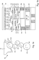
- Fig. 1a shows schematically a view of a filter feed device 10, the filter feed device 10 being integrated, for example, in a multifilter machine M schematically designated.
- Filter rods 100 are removed from a magazine 12 with filter rods 100 by means of a removal drum 14 and transported to cutting knives 16.1, 16.2, 16.3 arranged on the removal drum 14, on which the filter rods 100 are cut into several double-length filter plugs 111 to 118.
- the in Figure 1b The flowchart shown here is where the filter rods 100 are cut into filter plugs 111 to 118 on the removal drum.
- the filter plugs are also known as filter pieces.
- the cut filter plugs 111 to 118 are then transferred from the removal drum 14 to a staggered drum 18 on which the filter plugs 111 to 118 are staggered.
- the individual filter plugs 111 to 118 are arranged on the staggering drum 18 longitudinally axially and transversely axially offset to one another.
- the staggered filter plugs 111 to 118 are then transferred from the staggered drum 18 to a first push drum 20 so that the filter plugs 111 to 118 are displaced longitudinally axially outward on the push drum 20, with the push drum 20 or corresponding position stops on the receiving troughs 21, 22 of the sliding drum 20 (cf. Figure 4a ) are arranged, so that after displacement of the filter plugs 111 to 118, the filter plugs 111 to 118 are arranged in the receiving troughs 21, 22 at the position stops.
- the pusher drum 20 has two rows R1, R2 with receiving troughs 21, 22 arranged next to one another.
- the row R1 with the receiving troughs 21 receives the filter plugs 111 to 114, while the second row R2 with the receiving troughs 22 receives the filter plugs 115 to 118.
- the filter plugs 111 to 114 are moved axially outward by the application of suction air, and the filter plugs 115 to 118 accommodated in the receiving troughs 22 of the second row R2 are also moved outward in the opposite direction postponed.
- the receiving troughs 21 of the first row R1 and the receiving troughs 22 of the second row R2 are not arranged in alignment with one another in the longitudinal axial direction, so that the receiving troughs 21 and 22 are arranged offset from one another in the circumferential direction (cf. Figure 4a ).
- the filter plugs 111 to 118 are spaced apart from one another in the longitudinal axial direction at the outer ends of the receiving troughs 21, 22. Then the filter plugs 111 to 118 are transferred from the push drum 20 to a further, second push drum 24 in the receiving troughs 21, 22 of the second push drum 24, with the filter plugs 111 to 114 and the filter plugs 115 to 118 on the push drum 24 in the longitudinal axial direction in the continuous grooves of the second pusher drum 24 are moved inward against stops 26 and 28. Thereafter, the filter plugs 111 to 118 displaced on the second push drum 24 are transferred in pairs to a further conveyor drum 30.
- a combing device 31 is arranged on the sliding drum 20. As a result, the filter rods 111 to 114 are safely released into the receiving troughs 21.
- a combing device 32 is also provided for a reliable transfer of the filter plugs 115 to 118 into the receiving troughs 22 of the row R2 of the sliding drum 20.
- the combing device 31 and the combing device 32 arranged next to it differ in their geometrical dimensions, since the transfer points of the filter plugs 111 to 118 into the receiving troughs 21 and 22 arranged offset from one another are also different.
- a combing device 41 is located between the pushing drums 20, 24 for the filter plugs 111 to 114 which are arranged in the receiving troughs 21 and are axially displaced arranged.
- a combing device 42 is provided for the other filter plugs 115 to 118, which are positioned in the receiving troughs 22 of the row R1 on the outside.
- Fig. 2a is schematically shown a flow chart for a further shift drum 20 according to another embodiment.
- the receiving troughs 21 of the first row R1 and the receiving troughs 22 of the second row R2 are aligned with one another, with a gap 50 being formed between the two receiving trough rows R1, R2 so that the opposite ends of the trough webs of the receiving troughs 21 and the receiving troughs 22 are spaced apart.
- covers 61, 62 are arranged in the transfer area of the pusher drum 20, which are also spaced from one another, whereby a gap 50 also exists between the cover 61 and the cover 62. Due to the gap 50 between the covers 61 and 62 and the gap 50 between the receiving troughs 21 and 22, when the filter plugs 111 to 118 are moved axially to the outer sides of the sliding drum 20, pressure compensation is enabled by means of suction air, whereby the filter plugs 111 to 118 are reliably attached to the positioned on both outer sides.
- suction air bores are provided in the receiving troughs 21, 22 in the area of the outer sides, which are subjected to negative pressure, whereby the filter plugs 111 to 118 due to the negative pressure each pulled outwards.
- the receiving troughs 21 of the row R1 are arranged offset to the receiving troughs 22 of the row R2, so that the trough contours of the receiving troughs 21 and 22 are not aligned with one another.
- one end of a trough web of the respective other row of receiving troughs is arranged in the alignment of the receiving troughs 21 and 22, as a result of which a lateral mechanical barrier is formed between the two rows R1, R2.
- a gap 50 is formed between the two rows R1, R2.
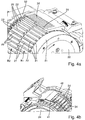
- FIG. 3 shows a schematic, perspective view of a drum arrangement with the first push drum 20 and the second push drum 24.
- Figure 4a shows a detailed view of the sliding drum 20, while in FIG Figure 4b schematically in detail a view of the second Push drum 24 is shown.
- a combing device 31 for the filter plugs 111 to 114, which are inserted into the deep receiving troughs 21 of the row R1 is arranged on the first sliding drum 20, the combing device 31 extending from the neighboring combing device 32 for the filter plugs 115 to 118 to Introducing into the receiving troughs 22 of the second row R2 differs in length.
- trough webs 27 and 29 respectively extending radially outward are formed.
- the receiving troughs 21 of the row R1 are arranged out of alignment with the receiving troughs 22 of the row R2, so that the receiving troughs 21 of the row R1 are arranged at an angle to the receiving troughs 22 of the row R2.
- the trough webs 29 each have a bevel or bevel 25 between the trough bottom of the receiving troughs 22.
- the bevel 25 for the respective trough bottom of the receiving troughs 22 is formed on the leading trough web 29 in the conveying direction.
- Outer rings 51, 52 are arranged laterally on the receiving troughs 21, 22 as position stops for the filter plugs, so that the filter plugs received in the receiving troughs 21, 22 are displaced outward in the direction of the rings 51, 52 and on the rings 51, 52 be positioned.
- FIG 4b A perspective view of the second push drum 24 is shown schematically, with the combing devices for transferring the filter plugs 111 to 118 positioned by longitudinally axial displacement on the first push drum 20 into the receiving troughs 34 of the push drum 24 41, 42 are arranged, which engage in corresponding grooves of the trough webs 27, 29 of the receiving troughs 21, 22.
- the receiving troughs 34 are designed to be continuous, so that two filter plugs 111 to 118 spaced apart from one another in the longitudinal axis are arranged on the outside of each receiving trough.
- the receiving troughs 34 are open at the outer ends, so that when negative pressure is applied to suction bores arranged in the middle of the receiving troughs 34, the filter plugs 111 to 118 arranged on the outer edge are displaced inward to the center of the receiving troughs 34.
- Fig. 5 is shown schematically a perspective view of a first sliding drum 20 according to a further embodiment.
- a combing device 31 and a combing device 32 for the filter plugs are shown on the first sliding drum 20, which are received in the deep receiving troughs of the two rows of receiving troughs of the sliding drums 20.
- the filter plugs After the filter plugs have been received in the two rows of the receiving troughs, the filter plugs are subjected to negative pressure in the deep troughs, for which the receiving troughs are designed with corresponding suction holes (cf. Fig. 3 , Fig. 4 ).
- a transfer bowl or delivery bowl 55 provided as an article transfer guide device is arranged on the sliding drum 20, so that the filter plugs conveyed in the receiving troughs are safely delivered to the following sliding drum.
- the dispensing tray 55 which is also referred to as the transfer tray, is shown in FIG a transfer area T of the pusher drum 20, in which the holding vacuum is switched off at the suction holes in the trough bottom or at the filter plugs, so that the filter plugs in the receiving troughs no longer rest with negative pressure in the receiving troughs and thus no longer contact the trough base of the respective Have receptacles.
- the dispensing tray 55 is arranged, which is tapered at the outgoing end, i.e. in the area to the next or following push drum.
- the filter plugs are conveyed along the inside or surface of the dispensing tray 55.
- this is also designed to taper to a point.
- a drum arrangement with the first push drum 20 and the second push drum 24 is shown schematically.
- the transfer of a number of filter plugs is shown schematically.
- the dispensing tray 55 is arranged on the sliding drum 20 in a transfer area T in which the holding vacuum at the suction holes of the receiving troughs is switched off, so that when the sliding drum 20 rotates, the filter plugs 111 to 114 roll off on the inside or surface facing the sliding drum 20. Because the filter plugs 111 to 114 are arranged in deep receiving troughs, they are spaced apart from one another in the transverse axial direction or in the conveying direction of the sliding drum 20, the filter plugs 111 to 114 rolling on the surface of the dispensing tray 55.
- the inner surface or surface of the dispensing bowl 55 is curved in order to ensure that the filter plugs 111 to 114 are guided reliably.
- the filter plugs 111, 114 roll on the inner surface and are attached to the receiving troughs at the end of the dispensing tray 55 subsequent push drum 24 passed. Before the transfer, the filter plugs 111 to 114 are no longer held in the receiving troughs and are guided on the inner path of the dispensing tray 55 by means of gravity and / or the centrifugal forces.
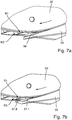
- FIGs 7a, 7b two different embodiments of a dispensing tray 55 or article transfer guide device for the filter plugs 111 to 118 or for the rod-shaped articles are shown.
- the in Figure 7a In the illustrated embodiment, the inner surface 56 facing the sliding drum 20 is the same over the entire width and has no cracks or the like. The inner surface 56 is thus uniform over the entire width for both rows R1, R2 of the receiving troughs of the sliding drum 20. At the incoming end and the outgoing end of the dispensing tray 55, the smooth inner surface 56 is each delimited with a straight end edge.
- the in Figure 7b The exemplary embodiment shown schematically shows the dispensing tray 55, the dispensing tray 55 having two end-side partial inner surfaces 57.1, 57.2 for the two rows R1, R2.
- an offset is provided between the partial inner surfaces 57.1, 57.2 in order to securely transfer the filter plugs to the receiving troughs of the subsequent push drum.
- the partial inner surfaces 57.1, 57.2 at the terminating end of the dispensing bowl are offset in height from one another by a step or the like.
- an inner surface can be provided over the entire width of the dispensing bowl 55, which is divided into the illustrated partial inner surfaces 57.1, 57.2 in relation to the conveying direction of the filter plugs at the outgoing end.
- Each of the partial inner surfaces 57.1, 57.2 offset from one another at the terminating end is each delimited by a straight end edge.
- the dispensing tray 55 is designed with a straight end edge at the inlet end.
- the partial inner surfaces 57.1, 57.2 are offset in height relative to the conveying direction continuously from the incoming end to the outgoing end of the dispensing tray 55, e.g. by a step or the like.
- FIG 8a a detailed view is shown in the transfer area of the pusher drum 20 to the downstream pusher drum (not shown here).
- the holding vacuum in the receiving troughs is switched off so that the filter plugs touch the inner surface 56 of the dispensing bowl 55 and are guided along the inner surface 56.
- FIG. 8b The schematic transfer process shown in the diagram from the push drum 20 to the following push drum shows that a tapering combing body 58 engages in a slot in the trough webs and guides the filter plugs into the receiving troughs of the following push drum during the transfer.
Landscapes
- Cigarettes, Filters, And Manufacturing Of Filters (AREA)
- Manufacturing Of Cigar And Cigarette Tobacco (AREA)
Claims (14)
- Agencement de tambours pour le transport selon un axe transversal d'articles en forme de tige de l'industrie de transformation du tabac, en particulier de tiges de filtre et/ou de pièces de filtre et/ou de produits segmentés, l'agencement de tambours comprenant deux tambours coulissants (20, 24) pour le déplacement selon un axe longitudinal des articles en forme de tige dans des cavités de réception (21, 22, 34), le premier tambour coulissant (20) étant conçu avec des cavités de réception (21, 22) pour des articles en forme de tige, le premier tambour coulissant (20) étant configuré de telle sorte que, pendant ou lors du transport des articles en forme de tige dans la direction d'axe transversal, les articles en forme de tige sont déplacés ou aptes à être déplacés selon l'axe longitudinal dans les cavités de réception (21, 22), les articles en forme de tige, après avoir été déplacés selon l'axe longitudinal sur le premier tambour coulissant (20), sont ensuite transférés ou sont aptes à être transférés du premier tambour coulissant (20) au deuxième tambour coulissant (24), et les articles en forme de tige transférés sont déplacés ou sont aptes à être déplacés selon l'axe longitudinal sur le deuxième tambour coulissant (24) dans les cavités de réception (34) du deuxième tambour coulissant (24), caractérisé en ce que le premier tambour coulissant (20) présente deux séries (R1, R2) de cavités de réception (21, 22) agencées l'une à côté de l'autre dans la direction d'axe transversal, les cavités étant les unes à la suite des autres dans la direction périphérique, les cavités de réception (21) de la première série de cavités de réception étant agencées ou orientées de manière non alignée par rapport aux cavités de réception (22) de la deuxième série (R2) de cavités de réception.
- Agencement de tambours selon la revendication 1, caractérisé en ce que les cavités de réception (21, 22) du premier tambour coulissant (20) comprennent des nervures de cavités (27, 29) et les extrémités intérieures des nervures de cavités (27) des cavités de réception (21) de la première série (R1) sont placées en face des extrémités intérieures des nervures de cavités (29) de la deuxième série (R2) et à une distance prédéterminée,et/ou en ce que des nervures de cavités (27) sont prévues entre les cavités de réception (21) de la première série (R1) et des nervures de cavités (29) sont prévues entre les cavités de réception (22) de la deuxième série (R2), une nervure de cavité (29) d'une cavité de réception (22) de la deuxième série (R2) étant agencée latéralement entre deux nervures de cavités (27) d'une cavité de réception (21) de la première série (R1) par rapport au fond de cavité des cavités de réception (21) de la première série (R1),et/ou en ce que les nervures de cavités (27) de la première série (R1) sont chacune agencées sous forme de délimitations latérales pour les cavités de réception (22) de la deuxième série (R2) et les nervures de cavités (29) de la deuxième série (R2) sont chacune agencées sous forme de délimitations latérales pour les cavités de réception (21) de la première série (R1).
- Agencement de tambours selon la revendication 1 ou la revendication 2, caractérisé en ce que les cavités de réception (21) de la première série (R1) et les cavités de réception (22) de la deuxième série (R2) sont formées chacune sur un corps de tambour, en particulier le premier corps de tambour étant relié aux cavités de réception (21) de la première série (R1) et le deuxième corps de tambour étant relié aux cavités de réception (22) de la deuxième série (R2).
- Agencement de tambours selon l'une quelconque des revendications 1 à 3, caractérisé en ce que des butées sont prévues sur les cavités de réception (21) de la première série (R1) et sur les cavités de réception (22) de la deuxième série (R2) aux extrémités des cavités de réception opposées les unes aux autres,
et/ou en ce que des butées sont prévues entre une zone de réception pour recevoir des articles en forme de tige dans les cavités de réception (21) de la première série (R1) et dans les cavités de réception (22) de la deuxième série (R2) à partir d'un tambour de transport prévu en amont dans la direction de transport, en particulier un tambour décalé, et au moins un dispositif de recouvrement étant prévu dans une zone de transfert pour transférer les articles en forme de tige, déplacés dans la direction d'axe longitudinal sur le premier tambour coulissant (20), depuis les cavités de réception, sur le deuxième tambour coulissant (24), le dispositif de recouvrement présentant en particulier un organe de recouvrement pour les cavités de réception (21) de la première série (R1) et un organe de recouvrement pour les cavités de réception (22) de la deuxième série (R2). - Agencement de tambours selon l'une des revendications 1 à 4, caractérisé en ce que le contour des cavités de réception (21) de la première série (R1) diffère du contour des cavités de réception (22) de la deuxième série (R2), le contour des cavités de réception d'une série présentant notamment un chanfrein, en particulier un chanfrein situé en avant du fond de la cavité par rapport à la direction de transport du tambour coulissant (20),
et/ou en ce que, dans la zone de réception d'articles en forme de tige, les cavités de réception des deux séries (R1, R2) présentent un dispositif de peignage pour les articles en forme de tige, le dispositif de peignage (31, 32) présentant en particulier un dispositif de peignage pour chaque série de cavités de réception (21, 22), et les dispositifs de peignage étant agencés de telle sorte que le point de transfert des articles en forme de tige vers les cavités de réception (21) de la première série (R1) diffère du point de transfert des articles en forme de tige dans les cavités de réception (22) de la deuxième série (R2) par rapport à la direction de transport. - Agencement de tambours selon l'une quelconque des revendications 1 à 5, caractérisé en ce que, en ce que les nervures de cavités (27) des cavités de réception (21) de la première série (R1) et/ou les nervures de cavités (29) des cavités de réception (22) de la deuxième série (R2) présentent au moins une ouverture dans la zone de bordure extérieure pour un dispositif de peignage prévu dans la zone de transfert sur le premier tambour coulissant (20) et/ou en ce que, dans la zone de transfert du premier tambour coulissant (20), pour transférer les articles en forme de tige dans des cavités de réception du deuxième tambour coulissant (24) qui suit dans la direction de transport, un dispositif de guidage de transfert d'articles est agencé sur le premier tambour coulissant (20) de sorte que, en particulier lorsque le vide de maintien est coupé au niveau des alésages d'aspiration des cavités de réception, les articles en forme de tige déplacés axialement dans la direction d'axe longitudinal sont guidés ou sont aptes à être guidés le long du dispositif de guidage de transfert pendant la rotation du premier tambour coulissant (20), le dispositif de guidage de transfert d'articles présentant en particulier un corps de guidage respectif pour les cavités de réception (21) de la première série (R1) et pour les cavités de réception (22) de la deuxième série (R2), les corps de guidage étant en outre différents notamment par leur géométrie.
- Agencement de tambours selon la revendication 1, caractérisé en ce que les cavités de réception du premier tambour coulissant (20) présentent au moins un ou plusieurs alésages d'aspiration afin d'appliquer un vide de maintien aux articles en forme de tige dans les cavités de réception ; dans une zone de transfert (T) du premier tambour coulissant (20), dans laquelle aucun vide de maintien n'est appliqué ou n'est apte à être appliqué aux articles en forme de tige transportés, un dispositif (55) de guidage de transfert d'articles est agencé ou est apte à être agencé sur le premier tambour coulissant (20), de sorte que, lorsque le vide de maintien n'est pas efficace dans la zone de transfert, les articles en forme de tige sont guidés ou aptes à être guidés le long du dispositif (55) de guidage de transfert d'articles pendant la rotation du premier tambour coulissant (20).
- Agencement de tambours selon la revendication 7, caractérisé en ce que le dispositif (55) de guidage de transfert d'articles est agencé ou est apte à être agencé, de préférence sur la moitié inférieure du premier tambour coulissant (20), dans une zone de transfert vers le deuxième tambour coulissant (24)
et/ou en ce que le dispositif (55) de guidage de transfert d'articles est conçu de façon effilée, de préférence se terminant en pointe, à son extrémité terminale. - Agencement de tambours selon la revendication 7 ou la revendication 8, caractérisé en ce que le dispositif (55) de guidage de transfert d'articles présente une surface courbe (56, 57.1, 57.2) tournée vers le premier tambour coulissant (20), le rayon de courbure de la surface (56, 57.1, 57.2) étant en particulier, à l'extrémité terminale du dispositif (55) de guidage de transfert d'articles, plus petit que le rayon de courbure de la surface (56, 57.1, 57.2) dans la zone, de préférence d'entrée et/ou médiane, du dispositif (55) de guidage de transfert d'articles.
- Agencement de tambours selon l'une quelconque des revendications 7 à 9, caractérisé en ce que le dispositif (55) de guidage de transfert d'articles présente une surface monobloc (56) tournée vers le premier tambour coulissant (20).
- Agencement de tambours selon l'une quelconque des revendications 7 à 9, caractérisé en ce que le dispositif (55) de guidage de transfert d'articles présente une surface formée avec un décalage et tournée vers le premier tambour coulissant (20), de sorte que deux parties de surfaces (57.1, 57.2) sont formées, chaque partie de surface (57.1, 57.2) du dispositif (55) de guidage de transfert d'articles étant associée à une série de cavités de réception du premier tambour coulissant (20), les extrémités terminales des parties de surfaces (57.1, 57.2) du dispositif (55) de guidage de transfert d'articles étant en particulier situées à des distances différentes par rapport aux fonds de cavité respectifs des cavités de réception tournées vers les parties de surfaces (57.1, 57.2).
- Agencement de tambours selon l'une des revendications 1 à 11, caractérisé en ce que le deuxième tambour coulissant (24) présente des cavités de réception (34) continues pour les articles en forme de tige, au moins une butée (26, 28), de préférence deux butées, pour les articles en forme de tige étant prévues en particulier entre les zones de bordure extérieures des cavités de réception (34) du deuxième tambour coulissant (24).
- Machine (M) de l'industrie de transformation du tabac, en particulier machine (M) de fixation de filtres ou machine de fabrication de filtres, ayant un agencement de tambours selon l'une des revendications 1 à 12, de préférence pour un dispositif (10) d'alimentation en filtres.
- Procédé de transport transversal d'articles en forme de tige de l'industrie de transformation du tabac, notamment de tiges de filtre et/ou de morceaux de filtre découpés dans des tiges de filtre, utilisant un agencement de tambours selon l'une quelconque des revendications 1 à 12.
Priority Applications (2)
| Application Number | Priority Date | Filing Date | Title |
|---|---|---|---|
| PL16182141T PL3141134T3 (pl) | 2015-08-20 | 2016-08-01 | Bęben przesuwający przemysłu przetwórstwa tytoniu |
| CN201610689757.5A CN106617282B (zh) | 2015-08-20 | 2016-08-19 | 烟草加工业的推移卷筒 |
Applications Claiming Priority (1)
| Application Number | Priority Date | Filing Date | Title |
|---|---|---|---|
| DE102015113820.4A DE102015113820A1 (de) | 2015-08-20 | 2015-08-20 | Schiebetrommel der Tabak verarbeitenden Industrie |
Publications (3)
| Publication Number | Publication Date |
|---|---|
| EP3141134A2 EP3141134A2 (fr) | 2017-03-15 |
| EP3141134A3 EP3141134A3 (fr) | 2017-06-21 |
| EP3141134B1 true EP3141134B1 (fr) | 2021-09-29 |
Family
ID=56557613
Family Applications (1)
| Application Number | Title | Priority Date | Filing Date |
|---|---|---|---|
| EP16182141.8A Active EP3141134B1 (fr) | 2015-08-20 | 2016-08-01 | Tambour coulissant de l'industrie de transformation du tabac |
Country Status (4)
| Country | Link |
|---|---|
| EP (1) | EP3141134B1 (fr) |
| CN (1) | CN106617282B (fr) |
| DE (1) | DE102015113820A1 (fr) |
| PL (1) | PL3141134T3 (fr) |
Families Citing this family (14)
| Publication number | Priority date | Publication date | Assignee | Title |
|---|---|---|---|---|
| DE102016114641A1 (de) * | 2016-08-08 | 2018-02-08 | Hauni Maschinenbau Gmbh | Fördertrommel der Tabak verarbeitenden Industrie |
| CN108002003B (zh) * | 2017-12-13 | 2020-03-03 | 红塔烟草(集团)有限责任公司 | 一种适于短烟支生产的分离导向传送机构 |
| DE102018104957A1 (de) | 2018-03-05 | 2019-09-05 | Hauni Maschinenbau Gmbh | Schiebetrommel der Tabak verarbeitenden Industrie |
| DE102018104956A1 (de) * | 2018-03-05 | 2019-09-05 | Hauni Maschinenbau Gmbh | Fördertrommel der Tabak verarbeitenden Industrie |
| CN109043656B (zh) * | 2018-09-27 | 2023-11-28 | 杨成云 | 一种三元复合卷烟滤嘴棒生产装置 |
| DE102019100210B4 (de) * | 2019-01-07 | 2023-01-26 | Körber Technologies Gmbh | Fördern von stabförmigen Artikeln der Tabak verarbeitenden Industrie |
| DE102020120519A1 (de) | 2020-08-04 | 2022-02-10 | Hauni Maschinenbau Gmbh | Schiebetrommel der Tabak verarbeitenden Industrie |
| DE102021101485A1 (de) | 2021-01-25 | 2022-07-28 | Hauni Maschinenbau Gmbh | Trommelanordnung zum queraxialen Fördern von stabförmigen Artikeln der Tabak verarbeitenden Industrie |
| IT202100010337A1 (it) * | 2021-04-23 | 2022-10-23 | Gd Spa | Unità multitamburo e metodo per processare articoli a forma di barretta dell’industria del tabacco |
| CN114523435B (zh) * | 2022-03-10 | 2024-01-09 | 郑州郑源实业有限公司 | 复合机用合一轮 |
| GB202219491D0 (en) * | 2022-12-22 | 2023-02-08 | Nicoventures Trading Ltd | Apparatus, components thereof and method for handling rods of aerosol-generating material |
| GB202219486D0 (en) * | 2022-12-22 | 2023-02-08 | Nicoventures Trading Ltd | Apparatus, components thereof and method for handling rods of aerosol-generating material |
| PL443569A1 (pl) * | 2023-01-25 | 2024-07-29 | International Tobacco Machinery Poland Spółka Z Ograniczoną Odpowiedzialnością | Urządzenie do wytwarzania artykułów wielosegmentowych |
| IT202300009354A1 (it) * | 2023-05-10 | 2024-11-10 | Gd Spa | Unita' per l'alimentazione di spezzoni per una macchina assemblatrice per la produzione di articoli multicomponente, macchina assemblatrice per la produzione di articoli multicomponente e metodo per l'alimentazione di spezzoni per la produzione di articoli multicomponente |
Family Cites Families (16)
| Publication number | Priority date | Publication date | Assignee | Title |
|---|---|---|---|---|
| US3715056A (en) * | 1969-12-31 | 1973-02-06 | Molins Machine Co Ltd | Handling apparatus for rod-like articles |
| DE3512445A1 (de) * | 1984-04-19 | 1985-10-31 | Hauni-Werke Körber & Co KG, 2050 Hamburg | Verfahren und vorrichtung zum bilden mehrlagiger bloecke aus stabfoermigen artikeln der tabakverarbeitenden industrie |
| GB9210681D0 (en) | 1992-05-19 | 1992-07-01 | Molins Plc | Filter cigarette manufacture |
| JP3368038B2 (ja) | 1994-03-31 | 2003-01-20 | 日本たばこ産業株式会社 | フィルタプラグ供給装置のグレーディング装置 |
| DE19858600A1 (de) | 1998-12-18 | 2000-06-21 | Hauni Maschinenbau Ag | Vorrichtung zum längsaxialen Positionieren von zu durchtrennenden stabförmigen Artikeln der tabakverarbeitenden Industrie |
| DE10156296A1 (de) * | 2001-11-19 | 2003-05-28 | Focke & Co | Vorrichtung zum Herstellen von Filterzigaretten |
| DE50205930D1 (de) * | 2002-12-05 | 2006-04-27 | Hauni Maschinenbau Ag | Multifunktionsfördertrommel |
| ITBO20030683A1 (it) * | 2003-11-17 | 2005-05-18 | Gd Spa | Tamburo centratore per macchine mettifiltro |
| DE102010002492A1 (de) * | 2010-03-02 | 2011-09-08 | Hauni Maschinenbau Ag | Fördertrommel der Tabak verarbeitenden Industrie |
| CN103220922A (zh) * | 2010-11-30 | 2013-07-24 | 豪尼机械制造股份公司 | 用于转运烟草加工业的棒状物品的设备和方法 |
| DE102011006025B3 (de) * | 2011-03-24 | 2012-07-19 | Hauni Maschinenbau Ag | Herstellung von Filterstopfen bzw. von Filterzigaretten |
| ITBO20110158A1 (it) * | 2011-03-28 | 2012-09-29 | Gd Spa | Tamburo di trasferimento o di accompagnamento per spezzoni di filtro o di sigaretta con teste operative portate da bracci radiali. |
| DE102011115713A1 (de) * | 2011-10-12 | 2013-04-18 | Hauni Maschinenbau Ag | Übernahmetrommel für eine Maschine zur Herstellung von Produkten der Tabak verarbeitenden Industrie |
| CN202552097U (zh) * | 2012-04-12 | 2012-11-28 | 绍兴市明宇机械制造有限公司 | 滤棒传输装置 |
| DE102012209032A1 (de) * | 2012-05-30 | 2013-12-05 | Hauni Maschinenbau Ag | Fördertrommel der Tabak verarbeitenden Industrie |
| DE102013201854A1 (de) * | 2013-02-05 | 2014-08-07 | Hauni Maschinenbau Ag | Förderung von stabförmigen Artikeln der Tabak verarbeitenden Industrie mit druckempfindlichen Objekten |
-
2015
- 2015-08-20 DE DE102015113820.4A patent/DE102015113820A1/de not_active Ceased
-
2016
- 2016-08-01 PL PL16182141T patent/PL3141134T3/pl unknown
- 2016-08-01 EP EP16182141.8A patent/EP3141134B1/fr active Active
- 2016-08-19 CN CN201610689757.5A patent/CN106617282B/zh active Active
Also Published As
| Publication number | Publication date |
|---|---|
| CN106617282B (zh) | 2021-08-03 |
| EP3141134A3 (fr) | 2017-06-21 |
| PL3141134T3 (pl) | 2022-01-31 |
| DE102015113820A1 (de) | 2017-02-23 |
| CN106617282A (zh) | 2017-05-10 |
| EP3141134A2 (fr) | 2017-03-15 |
Similar Documents
| Publication | Publication Date | Title |
|---|---|---|
| EP3141134B1 (fr) | Tambour coulissant de l'industrie de transformation du tabac | |
| EP3536173B1 (fr) | Tambour de transport de l'industrie de traitement du tabac | |
| EP2668857B1 (fr) | Tambour de transport de l'industrie de traitement du tabac | |
| EP3536172B1 (fr) | Tambour coulissant de l'industrie de traitement du tabac | |
| EP2328429A1 (fr) | Tambour de transport pour l'industrie de transformation du tabac | |
| EP1700528A1 (fr) | Tambour de coupe à coulisse | |
| EP3281537A2 (fr) | Tambour de transport de l'industrie de traitement du tabac | |
| DE102017127593A1 (de) | Schiebetrommel der Tabak verarbeitenden Industrie | |
| EP2862455B1 (fr) | Coupe d'articles en forme de tige de l'industrie de traitement du tabac | |
| EP2353408A2 (fr) | Tambour de transport de l'industrie de traitement du tabac | |
| EP2517582A2 (fr) | Bague d'aspiration pour un tambour de transport dans l'industrie de traitement du tabac | |
| DE102013210634A1 (de) | Schiebetrommel für eine Maschine der Tabak verarbeitenden Industrie | |
| EP3677128B1 (fr) | Transport d'articles en forme de tige de l'industrie de traitement du tabac | |
| EP1527703B1 (fr) | Tambour à gradins | |
| EP4369955B1 (fr) | Tambour de transport pour l'industrie de transformation du tabac | |
| EP4266913B1 (fr) | Agencement de tambour pour transporter des articles en forme de tige de l'industrie de transformation du tabac dans une direction axialement transversale | |
| EP4069001B1 (fr) | Tambour de transport pour l'industrie de transformation du tabac | |
| EP1897454A1 (fr) | Agencement en forme de V d'ouvertures d'aspiration | |
| DE102004057091B3 (de) | Einstoßtrommel | |
| DE102004028639A1 (de) | Fördertrommel der Tabak verarbeitenden Industrie | |
| EP3262959B1 (fr) | Positionnement de produits en forme de tiges de l'industrie de traitement du tabac dans une machine d'insertion | |
| EP3791731B1 (fr) | Tambour de transport de l'industrie de traitement du tabac | |
| EP4156980A1 (fr) | Tambour de poussée pour l'industrie de transformation du tabac | |
| EP1607008A1 (fr) | Tambour de transport de l'industrie du tabac | |
| DE102024116975A1 (de) | Trommelanordnung zum queraxialen Fördern von stabförmigen Artikeln der Tabak verarbeitenden Industrie |
Legal Events
| Date | Code | Title | Description |
|---|---|---|---|
| PUAI | Public reference made under article 153(3) epc to a published international application that has entered the european phase |
Free format text: ORIGINAL CODE: 0009012 |
|
| STAA | Information on the status of an ep patent application or granted ep patent |
Free format text: STATUS: THE APPLICATION HAS BEEN PUBLISHED |
|
| AK | Designated contracting states |
Kind code of ref document: A2 Designated state(s): AL AT BE BG CH CY CZ DE DK EE ES FI FR GB GR HR HU IE IS IT LI LT LU LV MC MK MT NL NO PL PT RO RS SE SI SK SM TR |
|
| AX | Request for extension of the european patent |
Extension state: BA ME |
|
| PUAL | Search report despatched |
Free format text: ORIGINAL CODE: 0009013 |
|
| AK | Designated contracting states |
Kind code of ref document: A3 Designated state(s): AL AT BE BG CH CY CZ DE DK EE ES FI FR GB GR HR HU IE IS IT LI LT LU LV MC MK MT NL NO PL PT RO RS SE SI SK SM TR |
|
| AX | Request for extension of the european patent |
Extension state: BA ME |
|
| RIC1 | Information provided on ipc code assigned before grant |
Ipc: A24C 5/47 20060101AFI20170518BHEP Ipc: A24C 5/32 20060101ALI20170518BHEP |
|
| STAA | Information on the status of an ep patent application or granted ep patent |
Free format text: STATUS: REQUEST FOR EXAMINATION WAS MADE |
|
| 17P | Request for examination filed |
Effective date: 20171215 |
|
| RBV | Designated contracting states (corrected) |
Designated state(s): AL AT BE BG CH CY CZ DE DK EE ES FI FR GB GR HR HU IE IS IT LI LT LU LV MC MK MT NL NO PL PT RO RS SE SI SK SM TR |
|
| GRAP | Despatch of communication of intention to grant a patent |
Free format text: ORIGINAL CODE: EPIDOSNIGR1 |
|
| STAA | Information on the status of an ep patent application or granted ep patent |
Free format text: STATUS: GRANT OF PATENT IS INTENDED |
|
| INTG | Intention to grant announced |
Effective date: 20210514 |
|
| GRAS | Grant fee paid |
Free format text: ORIGINAL CODE: EPIDOSNIGR3 |
|
| GRAA | (expected) grant |
Free format text: ORIGINAL CODE: 0009210 |
|
| STAA | Information on the status of an ep patent application or granted ep patent |
Free format text: STATUS: THE PATENT HAS BEEN GRANTED |
|
| RIN1 | Information on inventor provided before grant (corrected) |
Inventor name: JONAT, ILMAR Inventor name: HOFMANN, NILS Inventor name: VON BABKA-GOSTOMSKI, PHILIPP Inventor name: BOETTCHER, MAIK |
|
| AK | Designated contracting states |
Kind code of ref document: B1 Designated state(s): AL AT BE BG CH CY CZ DE DK EE ES FI FR GB GR HR HU IE IS IT LI LT LU LV MC MK MT NL NO PL PT RO RS SE SI SK SM TR |
|
| REG | Reference to a national code |
Ref country code: GB Ref legal event code: FG4D Free format text: NOT ENGLISH |
|
| REG | Reference to a national code |
Ref country code: DE Ref legal event code: R096 Ref document number: 502016013902 Country of ref document: DE |
|
| REG | Reference to a national code |
Ref country code: CH Ref legal event code: EP Ref country code: AT Ref legal event code: REF Ref document number: 1433452 Country of ref document: AT Kind code of ref document: T Effective date: 20211015 |
|
| REG | Reference to a national code |
Ref country code: IE Ref legal event code: FG4D Free format text: LANGUAGE OF EP DOCUMENT: GERMAN |
|
| REG | Reference to a national code |
Ref country code: LT Ref legal event code: MG9D |
|
| REG | Reference to a national code |
Ref country code: NL Ref legal event code: FP |
|
| PG25 | Lapsed in a contracting state [announced via postgrant information from national office to epo] |
Ref country code: HR Free format text: LAPSE BECAUSE OF FAILURE TO SUBMIT A TRANSLATION OF THE DESCRIPTION OR TO PAY THE FEE WITHIN THE PRESCRIBED TIME-LIMIT Effective date: 20210929 Ref country code: RS Free format text: LAPSE BECAUSE OF FAILURE TO SUBMIT A TRANSLATION OF THE DESCRIPTION OR TO PAY THE FEE WITHIN THE PRESCRIBED TIME-LIMIT Effective date: 20210929 Ref country code: SE Free format text: LAPSE BECAUSE OF FAILURE TO SUBMIT A TRANSLATION OF THE DESCRIPTION OR TO PAY THE FEE WITHIN THE PRESCRIBED TIME-LIMIT Effective date: 20210929 Ref country code: NO Free format text: LAPSE BECAUSE OF FAILURE TO SUBMIT A TRANSLATION OF THE DESCRIPTION OR TO PAY THE FEE WITHIN THE PRESCRIBED TIME-LIMIT Effective date: 20211229 Ref country code: FI Free format text: LAPSE BECAUSE OF FAILURE TO SUBMIT A TRANSLATION OF THE DESCRIPTION OR TO PAY THE FEE WITHIN THE PRESCRIBED TIME-LIMIT Effective date: 20210929 Ref country code: BG Free format text: LAPSE BECAUSE OF FAILURE TO SUBMIT A TRANSLATION OF THE DESCRIPTION OR TO PAY THE FEE WITHIN THE PRESCRIBED TIME-LIMIT Effective date: 20211229 Ref country code: LT Free format text: LAPSE BECAUSE OF FAILURE TO SUBMIT A TRANSLATION OF THE DESCRIPTION OR TO PAY THE FEE WITHIN THE PRESCRIBED TIME-LIMIT Effective date: 20210929 |
|
| PG25 | Lapsed in a contracting state [announced via postgrant information from national office to epo] |
Ref country code: LV Free format text: LAPSE BECAUSE OF FAILURE TO SUBMIT A TRANSLATION OF THE DESCRIPTION OR TO PAY THE FEE WITHIN THE PRESCRIBED TIME-LIMIT Effective date: 20210929 Ref country code: GR Free format text: LAPSE BECAUSE OF FAILURE TO SUBMIT A TRANSLATION OF THE DESCRIPTION OR TO PAY THE FEE WITHIN THE PRESCRIBED TIME-LIMIT Effective date: 20211230 |
|
| PG25 | Lapsed in a contracting state [announced via postgrant information from national office to epo] |
Ref country code: IS Free format text: LAPSE BECAUSE OF FAILURE TO SUBMIT A TRANSLATION OF THE DESCRIPTION OR TO PAY THE FEE WITHIN THE PRESCRIBED TIME-LIMIT Effective date: 20220129 Ref country code: SK Free format text: LAPSE BECAUSE OF FAILURE TO SUBMIT A TRANSLATION OF THE DESCRIPTION OR TO PAY THE FEE WITHIN THE PRESCRIBED TIME-LIMIT Effective date: 20210929 Ref country code: RO Free format text: LAPSE BECAUSE OF FAILURE TO SUBMIT A TRANSLATION OF THE DESCRIPTION OR TO PAY THE FEE WITHIN THE PRESCRIBED TIME-LIMIT Effective date: 20210929 Ref country code: PT Free format text: LAPSE BECAUSE OF FAILURE TO SUBMIT A TRANSLATION OF THE DESCRIPTION OR TO PAY THE FEE WITHIN THE PRESCRIBED TIME-LIMIT Effective date: 20220131 Ref country code: ES Free format text: LAPSE BECAUSE OF FAILURE TO SUBMIT A TRANSLATION OF THE DESCRIPTION OR TO PAY THE FEE WITHIN THE PRESCRIBED TIME-LIMIT Effective date: 20210929 Ref country code: EE Free format text: LAPSE BECAUSE OF FAILURE TO SUBMIT A TRANSLATION OF THE DESCRIPTION OR TO PAY THE FEE WITHIN THE PRESCRIBED TIME-LIMIT Effective date: 20210929 Ref country code: CZ Free format text: LAPSE BECAUSE OF FAILURE TO SUBMIT A TRANSLATION OF THE DESCRIPTION OR TO PAY THE FEE WITHIN THE PRESCRIBED TIME-LIMIT Effective date: 20210929 Ref country code: AL Free format text: LAPSE BECAUSE OF FAILURE TO SUBMIT A TRANSLATION OF THE DESCRIPTION OR TO PAY THE FEE WITHIN THE PRESCRIBED TIME-LIMIT Effective date: 20210929 |
|
| REG | Reference to a national code |
Ref country code: DE Ref legal event code: R097 Ref document number: 502016013902 Country of ref document: DE |
|
| PG25 | Lapsed in a contracting state [announced via postgrant information from national office to epo] |
Ref country code: DK Free format text: LAPSE BECAUSE OF FAILURE TO SUBMIT A TRANSLATION OF THE DESCRIPTION OR TO PAY THE FEE WITHIN THE PRESCRIBED TIME-LIMIT Effective date: 20210929 |
|
| PLBE | No opposition filed within time limit |
Free format text: ORIGINAL CODE: 0009261 |
|
| STAA | Information on the status of an ep patent application or granted ep patent |
Free format text: STATUS: NO OPPOSITION FILED WITHIN TIME LIMIT |
|
| 26N | No opposition filed |
Effective date: 20220630 |
|
| REG | Reference to a national code |
Ref country code: DE Ref legal event code: R081 Ref document number: 502016013902 Country of ref document: DE Owner name: KOERBER TECHNOLOGIES GMBH, DE Free format text: FORMER OWNER: HAUNI MASCHINENBAU GMBH, 21033 HAMBURG, DE |
|
| REG | Reference to a national code |
Ref country code: NL Ref legal event code: HC Owner name: KOERBER TECHNOLOGIES GMBH; DE Free format text: DETAILS ASSIGNMENT: CHANGE OF OWNER(S), CHANGE OF OWNER(S) NAME; FORMER OWNER NAME: HAUNI MASCHINENBAU GMBH Effective date: 20221025 |
|
| PG25 | Lapsed in a contracting state [announced via postgrant information from national office to epo] |
Ref country code: SI Free format text: LAPSE BECAUSE OF FAILURE TO SUBMIT A TRANSLATION OF THE DESCRIPTION OR TO PAY THE FEE WITHIN THE PRESCRIBED TIME-LIMIT Effective date: 20210929 |
|
| PG25 | Lapsed in a contracting state [announced via postgrant information from national office to epo] |
Ref country code: MC Free format text: LAPSE BECAUSE OF FAILURE TO SUBMIT A TRANSLATION OF THE DESCRIPTION OR TO PAY THE FEE WITHIN THE PRESCRIBED TIME-LIMIT Effective date: 20210929 |
|
| REG | Reference to a national code |
Ref country code: CH Ref legal event code: PL |
|
| GBPC | Gb: european patent ceased through non-payment of renewal fee |
Effective date: 20220801 |
|
| PG25 | Lapsed in a contracting state [announced via postgrant information from national office to epo] |
Ref country code: LU Free format text: LAPSE BECAUSE OF NON-PAYMENT OF DUE FEES Effective date: 20220801 Ref country code: LI Free format text: LAPSE BECAUSE OF NON-PAYMENT OF DUE FEES Effective date: 20220831 Ref country code: CH Free format text: LAPSE BECAUSE OF NON-PAYMENT OF DUE FEES Effective date: 20220831 |
|
| REG | Reference to a national code |
Ref country code: BE Ref legal event code: MM Effective date: 20220831 |
|
| P01 | Opt-out of the competence of the unified patent court (upc) registered |
Effective date: 20230621 |
|
| PG25 | Lapsed in a contracting state [announced via postgrant information from national office to epo] |
Ref country code: IE Free format text: LAPSE BECAUSE OF NON-PAYMENT OF DUE FEES Effective date: 20220801 Ref country code: FR Free format text: LAPSE BECAUSE OF NON-PAYMENT OF DUE FEES Effective date: 20220831 |
|
| PG25 | Lapsed in a contracting state [announced via postgrant information from national office to epo] |
Ref country code: BE Free format text: LAPSE BECAUSE OF NON-PAYMENT OF DUE FEES Effective date: 20220831 |
|
| REG | Reference to a national code |
Ref country code: AT Ref legal event code: MM01 Ref document number: 1433452 Country of ref document: AT Kind code of ref document: T Effective date: 20220801 |
|
| PG25 | Lapsed in a contracting state [announced via postgrant information from national office to epo] |
Ref country code: GB Free format text: LAPSE BECAUSE OF NON-PAYMENT OF DUE FEES Effective date: 20220801 Ref country code: AT Free format text: LAPSE BECAUSE OF NON-PAYMENT OF DUE FEES Effective date: 20220801 |
|
| PG25 | Lapsed in a contracting state [announced via postgrant information from national office to epo] |
Ref country code: HU Free format text: LAPSE BECAUSE OF FAILURE TO SUBMIT A TRANSLATION OF THE DESCRIPTION OR TO PAY THE FEE WITHIN THE PRESCRIBED TIME-LIMIT; INVALID AB INITIO Effective date: 20160801 |
|
| PG25 | Lapsed in a contracting state [announced via postgrant information from national office to epo] |
Ref country code: SM Free format text: LAPSE BECAUSE OF FAILURE TO SUBMIT A TRANSLATION OF THE DESCRIPTION OR TO PAY THE FEE WITHIN THE PRESCRIBED TIME-LIMIT Effective date: 20210929 Ref country code: MK Free format text: LAPSE BECAUSE OF FAILURE TO SUBMIT A TRANSLATION OF THE DESCRIPTION OR TO PAY THE FEE WITHIN THE PRESCRIBED TIME-LIMIT Effective date: 20210929 Ref country code: CY Free format text: LAPSE BECAUSE OF FAILURE TO SUBMIT A TRANSLATION OF THE DESCRIPTION OR TO PAY THE FEE WITHIN THE PRESCRIBED TIME-LIMIT Effective date: 20210929 |
|
| PG25 | Lapsed in a contracting state [announced via postgrant information from national office to epo] |
Ref country code: TR Free format text: LAPSE BECAUSE OF FAILURE TO SUBMIT A TRANSLATION OF THE DESCRIPTION OR TO PAY THE FEE WITHIN THE PRESCRIBED TIME-LIMIT Effective date: 20210929 |
|
| PG25 | Lapsed in a contracting state [announced via postgrant information from national office to epo] |
Ref country code: MT Free format text: LAPSE BECAUSE OF FAILURE TO SUBMIT A TRANSLATION OF THE DESCRIPTION OR TO PAY THE FEE WITHIN THE PRESCRIBED TIME-LIMIT Effective date: 20210929 |
|
| PGFP | Annual fee paid to national office [announced via postgrant information from national office to epo] |
Ref country code: NL Payment date: 20250826 Year of fee payment: 10 |
|
| PGFP | Annual fee paid to national office [announced via postgrant information from national office to epo] |
Ref country code: DE Payment date: 20250821 Year of fee payment: 10 |
|
| PGFP | Annual fee paid to national office [announced via postgrant information from national office to epo] |
Ref country code: PL Payment date: 20250721 Year of fee payment: 10 Ref country code: IT Payment date: 20250827 Year of fee payment: 10 |