EP3141204A1 - Systeme d'ablation destine a la coagulation extensive de tissus biologiques - Google Patents
Systeme d'ablation destine a la coagulation extensive de tissus biologiques Download PDFInfo
- Publication number
- EP3141204A1 EP3141204A1 EP15184689.6A EP15184689A EP3141204A1 EP 3141204 A1 EP3141204 A1 EP 3141204A1 EP 15184689 A EP15184689 A EP 15184689A EP 3141204 A1 EP3141204 A1 EP 3141204A1
- Authority
- EP
- European Patent Office
- Prior art keywords
- ablation
- ablation system
- endoscope
- ablation probe
- spark plasma
- Prior art date
- Legal status (The legal status is an assumption and is not a legal conclusion. Google has not performed a legal analysis and makes no representation as to the accuracy of the status listed.)
- Granted
Links
Images


Classifications
-
- A—HUMAN NECESSITIES
- A61—MEDICAL OR VETERINARY SCIENCE; HYGIENE
- A61B—DIAGNOSIS; SURGERY; IDENTIFICATION
- A61B18/00—Surgical instruments, devices or methods for transferring non-mechanical forms of energy to or from the body
- A61B18/04—Surgical instruments, devices or methods for transferring non-mechanical forms of energy to or from the body by heating
- A61B18/042—Surgical instruments, devices or methods for transferring non-mechanical forms of energy to or from the body by heating using additional gas becoming plasma
-
- A—HUMAN NECESSITIES
- A61—MEDICAL OR VETERINARY SCIENCE; HYGIENE
- A61B—DIAGNOSIS; SURGERY; IDENTIFICATION
- A61B18/00—Surgical instruments, devices or methods for transferring non-mechanical forms of energy to or from the body
- A61B18/04—Surgical instruments, devices or methods for transferring non-mechanical forms of energy to or from the body by heating
- A61B18/12—Surgical instruments, devices or methods for transferring non-mechanical forms of energy to or from the body by heating by passing a current through the tissue to be heated, e.g. high-frequency current
- A61B18/14—Probes or electrodes therefor
-
- A—HUMAN NECESSITIES
- A61—MEDICAL OR VETERINARY SCIENCE; HYGIENE
- A61B—DIAGNOSIS; SURGERY; IDENTIFICATION
- A61B1/00—Instruments for performing medical examinations of the interior of cavities or tubes of the body by visual or photographical inspection, e.g. endoscopes; Illuminating arrangements therefor
- A61B1/005—Flexible endoscopes
-
- A—HUMAN NECESSITIES
- A61—MEDICAL OR VETERINARY SCIENCE; HYGIENE
- A61N—ELECTROTHERAPY; MAGNETOTHERAPY; RADIATION THERAPY; ULTRASOUND THERAPY
- A61N1/00—Electrotherapy; Circuits therefor
-
- A—HUMAN NECESSITIES
- A61—MEDICAL OR VETERINARY SCIENCE; HYGIENE
- A61B—DIAGNOSIS; SURGERY; IDENTIFICATION
- A61B18/00—Surgical instruments, devices or methods for transferring non-mechanical forms of energy to or from the body
- A61B2018/00315—Surgical instruments, devices or methods for transferring non-mechanical forms of energy to or from the body for treatment of particular body parts
- A61B2018/00482—Digestive system
- A61B2018/00494—Stomach, intestines or bowel
-
- A—HUMAN NECESSITIES
- A61—MEDICAL OR VETERINARY SCIENCE; HYGIENE
- A61B—DIAGNOSIS; SURGERY; IDENTIFICATION
- A61B18/00—Surgical instruments, devices or methods for transferring non-mechanical forms of energy to or from the body
- A61B2018/00571—Surgical instruments, devices or methods for transferring non-mechanical forms of energy to or from the body for achieving a particular surgical effect
- A61B2018/00577—Ablation
-
- A—HUMAN NECESSITIES
- A61—MEDICAL OR VETERINARY SCIENCE; HYGIENE
- A61B—DIAGNOSIS; SURGERY; IDENTIFICATION
- A61B18/00—Surgical instruments, devices or methods for transferring non-mechanical forms of energy to or from the body
- A61B2018/00571—Surgical instruments, devices or methods for transferring non-mechanical forms of energy to or from the body for achieving a particular surgical effect
- A61B2018/00577—Ablation
- A61B2018/00583—Coblation, i.e. ablation using a cold plasma
-
- A—HUMAN NECESSITIES
- A61—MEDICAL OR VETERINARY SCIENCE; HYGIENE
- A61B—DIAGNOSIS; SURGERY; IDENTIFICATION
- A61B18/00—Surgical instruments, devices or methods for transferring non-mechanical forms of energy to or from the body
- A61B2018/00571—Surgical instruments, devices or methods for transferring non-mechanical forms of energy to or from the body for achieving a particular surgical effect
- A61B2018/00589—Coagulation
-
- A—HUMAN NECESSITIES
- A61—MEDICAL OR VETERINARY SCIENCE; HYGIENE
- A61B—DIAGNOSIS; SURGERY; IDENTIFICATION
- A61B18/00—Surgical instruments, devices or methods for transferring non-mechanical forms of energy to or from the body
- A61B2018/00571—Surgical instruments, devices or methods for transferring non-mechanical forms of energy to or from the body for achieving a particular surgical effect
- A61B2018/00607—Coagulation and cutting with the same instrument
-
- A—HUMAN NECESSITIES
- A61—MEDICAL OR VETERINARY SCIENCE; HYGIENE
- A61B—DIAGNOSIS; SURGERY; IDENTIFICATION
- A61B18/00—Surgical instruments, devices or methods for transferring non-mechanical forms of energy to or from the body
- A61B2018/00636—Sensing and controlling the application of energy
- A61B2018/00696—Controlled or regulated parameters
- A61B2018/00702—Power or energy
-
- A—HUMAN NECESSITIES
- A61—MEDICAL OR VETERINARY SCIENCE; HYGIENE
- A61B—DIAGNOSIS; SURGERY; IDENTIFICATION
- A61B18/00—Surgical instruments, devices or methods for transferring non-mechanical forms of energy to or from the body
- A61B2018/00636—Sensing and controlling the application of energy
- A61B2018/00696—Controlled or regulated parameters
- A61B2018/00732—Frequency
-
- A—HUMAN NECESSITIES
- A61—MEDICAL OR VETERINARY SCIENCE; HYGIENE
- A61B—DIAGNOSIS; SURGERY; IDENTIFICATION
- A61B18/00—Surgical instruments, devices or methods for transferring non-mechanical forms of energy to or from the body
- A61B2018/00636—Sensing and controlling the application of energy
- A61B2018/00696—Controlled or regulated parameters
- A61B2018/00767—Voltage
-
- A—HUMAN NECESSITIES
- A61—MEDICAL OR VETERINARY SCIENCE; HYGIENE
- A61B—DIAGNOSIS; SURGERY; IDENTIFICATION
- A61B18/00—Surgical instruments, devices or methods for transferring non-mechanical forms of energy to or from the body
- A61B2018/00982—Surgical instruments, devices or methods for transferring non-mechanical forms of energy to or from the body combined with or comprising means for visual or photographic inspections inside the body, e.g. endoscopes
-
- A—HUMAN NECESSITIES
- A61—MEDICAL OR VETERINARY SCIENCE; HYGIENE
- A61B—DIAGNOSIS; SURGERY; IDENTIFICATION
- A61B18/00—Surgical instruments, devices or methods for transferring non-mechanical forms of energy to or from the body
- A61B18/04—Surgical instruments, devices or methods for transferring non-mechanical forms of energy to or from the body by heating
- A61B18/12—Surgical instruments, devices or methods for transferring non-mechanical forms of energy to or from the body by heating by passing a current through the tissue to be heated, e.g. high-frequency current
- A61B18/14—Probes or electrodes therefor
- A61B2018/1467—Probes or electrodes therefor using more than two electrodes on a single probe
-
- A—HUMAN NECESSITIES
- A61—MEDICAL OR VETERINARY SCIENCE; HYGIENE
- A61B—DIAGNOSIS; SURGERY; IDENTIFICATION
- A61B2218/00—Details of surgical instruments, devices or methods for transferring non-mechanical forms of energy to or from the body
- A61B2218/001—Details of surgical instruments, devices or methods for transferring non-mechanical forms of energy to or from the body having means for irrigation and/or aspiration of substances to and/or from the surgical site
- A61B2218/002—Irrigation
- A61B2218/005—Irrigation using gas or vapor, e.g. for protection or purging
Definitions
- the invention relates to an ablation system, in particular for large-area mucosa ablation.
- the gastric mucosa for example for tumor resection or also for changing the eating and weighting behavior of the patient, it may be necessary to remove and / or coagulate sharply defined areas of the mucosa and the submucosa over a large area, the coagulation depth in the treated area should be as uniform as possible, so that the muscularis is not destroyed.
- Therapeutic mucosa ablation is typically performed by endoscope, whereby special probes may be used for ablation.
- an endoscope with an end cap which is to be placed on the mucosa and within which an argon-plasma coagulation is performed.
- the cap is intended to limit the area of action of argon plasma coagulation.
- the US 8 641 711 B2 describes an instrument for ablating tissue layers of hollow organs, the instrument having an electrically active head with electrodes.
- An expandable member is provided on the head to position the head defined with respect to the opposing tissue wall.
- the US 2004/0215180 A1 discloses an ablation probe having a plurality of wire-like individual electrodes projecting from the distal end of the probe, which are connected together to an electrical conductor and are supplied via this by a current generator with an ablation-causing current.
- FIG. 12 illustrates a probe for contact coagulation with a plurality of electrodes which, in use, are connected to the tissue adjacent one after another in a timely manner according to a particular circuit diagram with an RF generator.
- At least two plasma jets emanate from the ablation probe, which impinge directly adjacent to one another on the tissue to be treated.
- the plasma jets are alternately energized (excited), i. the two spark plasma electrodes ignite alternately.
- the two plasma jets can combine to form a beam with a flattened oval cross section, strip cross section or the like. When the plasma jet crosses the tissue across the length of its cross-section, a broad band of tissue is coagulated.
- the average power can be limited so that the Ablationstiefe is limited to a desired level and damage deep tissue or even Perforation of the treated hollow organ can be avoided.
- the mentioned effects are particularly noticeable when the spark plasma electrodes are arranged facing away from one another in an acute angle which opens in the distal direction.
- the treatment width is maximized, with the outer dimensions of the plasma ablation probe as low as possible, and in any case lower, than parallel plasma spark electrodes which would produce a comparable treatment width.
- the ablation probe has two adjacent gas outlet nozzles, wherein in each gas outlet nozzle in each case one of the spark plasma electrodes is arranged.
- the gas discharge nozzles are preferably arranged facing away from each other in an acute angle which opens in the distal direction, so that the generated plasma jets diverge slightly.
- the two spark plasma electrodes in a single gas outlet nozzle, which may for example be out of round, for example elongated as a slot nozzle, to produce a fan-shaped plasma jet.
- the ablation probe may be provided with a single fluid conduit for gas supply or also with two separate fluid conduits serving for its gas supply.
- the two spark plasma electrodes are supplied by two electrical lines with voltage, which are preferably arranged electrically coupled to each other.
- the coupling may be a capacitive coupling, which is provided by the two electrical lines being guided in parallel with each other at a small distance, so that a capacitance of at least some between both lines (ie the respective live line and the floating line) Picofarad is advantageous to measure 45 picofarads (pF).
- the switch arrangement can, for example, with a frequency between 1 and 20 Hz, preferably with a frequency of 5 Hz continuously, so that the two spark plasma electrodes are alternately connected to the RF voltage source.
- a line is connected to the RF voltage source and the other line is de-energized (potential-free).
- the switch arrangement is preferably arranged on the generator. Due to the (capacitive) coupling of both lines, a small capacitive current flows through the deactivated spark plasma electrode in the respective switch-off phase, which prevents complete recombination of the plasma during this short operating phase.
- both spark plasma electrodes can be connected to the RF source for a short time.
- the pre-ionization of the plasma at the hitherto inactive electrode facilitates during this short phase the resumption of operation of the previously momentarily inactive spark plasma electrode despite the relatively low voltage as a result of the operation of the other electrode.
- the switching is slightly leaky, i. In a brief moment when none of the electrodes is connected to the RF electrode, the previously inactive electrode ignites easily and without the RF voltage source forming too large a voltage spike. This will avoid sparking, which could lead to unwanted tissue damage.
- the ablation probe is typically used endoscopically. For this purpose, it is preferably attached to an endoscope outside the lumen thereof and held by means of an adapter at its distal end.
- the endoscope and the ablation probe can be arranged in different lumens of a plastic film tube.
- the endoscope remains available for other functions, ie for other instruments, for the supply or discharge of fluids, for the optical inspection and / or for the illumination of the operating area.
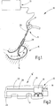
- FIG. 1 Figure 11 illustrates an ablation system 10 that includes an endoscope 11 with an ablation probe 12 and a device 13 for providing media and operating power to the ablation probe 12 and optionally other instruments.
- the ablation probe 12 is used for the treatment, in particular coagulation and / or ablation, of the inner skin of a hollow organ, in particular the mucosa 14 of a stomach 15.
- the distal end 16 of the endoscope 11 is guided and curved by means of operating elements 17 such that the ablation probe 12, in particular a head 18 provided at its distal end is advantageously perpendicular to the mucosa 14 at the desired distance and is moved along the same.
- the distal end 16 of the endoscope 11 and the ablation probe 12 are in FIG FIG. 2 shown separately.
- the endoscope 11 is formed as a single or multi-lumen by means of the controls 17 selectively bendable tube.
- an adapter 19 is held, which belongs to the ablation probe 12.
- the ablation probe 12 includes the head 18 which, as in FIG. 2 indicated by a double arrow, is movable in the longitudinal direction of the end 16 of the endoscope 11, and a tension and pressure stiffer hose 20, for example a fluid line 20 which is fixedly connected to the head 18 and extends parallel to the endoscope 11.
- the tube 20 leads, as FIG.
- the endoscope 11 and the tube 20 may be received by a tubular sheath 21, the ablation probe 12 extending through a first lumen 22, the tubular sheath 21 and the endoscope 11 through a second lumen 23 of the tubular sheath 21 ,
- the overall assembly consisting of endoscope 11, ablation probe 12 and tubular sheath 21, can be inserted through a gullet 24 into the stomach 15 of a patient as a conventional endoscope and controlled therein for movement.
- FIG. 3 illustrates the thus far described end 16 of the endoscope 11 again in perspective.
- the endoscope 11 may include one or more lumens 25 as well as image transfer means, illumination means, and the like.
- the adapter 19 may be secured by suitable clamping means or other fastening members at the end of the endoscope 11.
- FIG. 4 indicates that the head 18 may have a non-circular cross-section, with these two gas outlet nozzles 26, 27 may be provided. These may be formed, for example, as ceramic inserts.
- the gas outlet nozzles 26, 27 At least at the distal end 28 of the head 18, the gas outlet nozzles 26, 27 on opening axes 29, 30, which ⁇ preferably enclose an acute angle. This is preferably between 10 ° and 60 ° and is more preferably 10 ° to 30 °, in particular substantially 25 °.
- spark plasma electrodes 31, 32 Concentric with the exit axes 29, 30 spark plasma electrodes 31, 32 are provided, which are formed for example by needle or pin-shaped tungsten body or by other electrically conductive, thermally stable elements.
- the central spark plasma electrodes 31, 32 arranged in the gas outlet nozzles are preferably likewise arranged at an acute angle of preferably 10 ° to 60 °, preferably 10 ° to 30 °, in particular 25 °.
- the distance of the spark plasma electrodes 31, 32 from each other is preferably 5 mm to 10 mm, preferably 7.5 mm.
- the spark plasma electrodes 31, 32 may be disposed entirely within the gas discharge nozzles 26, 27 or may be partially protruded therefrom as shown in FIG FIG. 5 is shown.
- the spark plasma electrodes 31, 32 are each connected to an electrical line 33, 34, whose conductor is provided with an electrical insulation, ie a dielectric.
- the conduits 33, 34 both extend side by side through the lumen of the tube 20, which terminates at the proximal end 35 of the head 18 for gas supply to the gas outlet nozzles 26, 27 is connected.
- the lines can be twisted together, be designed as a bridge line or lie in the tube 20 loosely next to each other.
- a fluid line 36 can be provided in the tube 20, which serves to supply liquid, for example water (NaCl solution), to a liquid ejection nozzle 37 provided at the distal end of the head 28.
- the fluid line 36 may alternatively be guided outside the tube 20 along the outside thereof.
- the liquid ejection nozzle 37 can be used to inject the mucosa 14 with a liquid, in particular NaCl solution, in order to lift it from underlying tissue, in particular the submucosa 51.
- one or more bubble-like fluid depots can be created under the mucosa 14. This can e.g. before the application of HF current.
- liquid Prior to thermal ablation of the mucosa 42 by way of example, liquid can be introduced into the stomach wall through the outlet opening 37 in such a way that a fluid cushion advantageously forms below the desired ablation site.
- FIG. 2 illustrates a modified embodiment of the ablation probe as ablation probe 12a.
- This has a head 18a, the gas outlet nozzles 26, 27 are supplied by separate tension and pressure resistant tubes 20a, 20b with gas.
- the spark plasma electrodes 31, 32 can in turn be arranged out of the gas outlet nozzles 26, 27, or sunk into them, as shown.
- the electrical leads 33, 34 connected to the spark plasma electrodes 31, 32 may be insulated or led, as shown, as naked conductors through the tubes 20a, 20b, which run parallel to each other along the endoscope 11 and extend through the lumen 22 ( corresponding FIG. 3 ). Otherwise, the to describe the ablation probe 12 in connection with the FIGS. 1 to 5 given explanations accordingly.
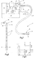
- Device 13 To supply the ablation probe 12 is used in FIG. 7 Device 13 illustrated in more detail.
- Device 13 includes an electrical source 38, such as an RF generator 38, which typically oscillates at a frequency between 100 kHz and one MHz, preferably at a frequency of, for example, 300 kHz to 400 kHz, especially 350 kHz , He receives his energy supply from a network and control part 39.
- an electrical source 38 such as an RF generator 38, which typically oscillates at a frequency between 100 kHz and one MHz, preferably at a frequency of, for example, 300 kHz to 400 kHz, especially 350 kHz , He receives his energy supply from a network and control part 39.
- High-frequency alternating voltage coupled out from the HF generator 38 is alternately applied via a switch arrangement 40 to the lines 33, 34 and thus alternately to the spark plasma electrodes 31, 32.
- the switch assembly 40 may be part of the device 13 or housed in a separate intermediate module which is connected to the device 13 and to which the lines 33, 34 are connected.
- the RF voltage applied alternately to the lines 33, 34 has a peak value of preferably several thousand volts (for example 5000 V), so that it is able to ignite sparks at the spark plasma electrodes 31, 32, which are incident on the spark plasma electrodes 31, 32 opposite biological tissues, for example the mucosa 14 (FIG. FIG. 6 ), skip.
- a neutral electrode 41 is provided, which is connected to the device 13 and to be attached over a large area to the patient.
- the switch assembly 40 includes a first switch 42 that can connect the line 33 to the RF generator 38, and a second switch 43 that can connect the line 34 to the RF generator 38.
- the switches or closing contacts 42, 43 are, for example, part of a relay or two separate relays, which switch in opposite directions.
- a clock signal T from the network and control part.
- the signal T is used by an amplifier and inverter block 44 for the opposite control of the switches 42, 43 moving drives.
- the first switch 42 and the second switch 43 operate alternately, so that the switch 42 is open when the switch 43 is closed and vice versa.
- the two switches 42, 43 may be closed for a short time both briefly or both be open in lückendem operation.
- the time of overlapping closure (both closed) or switching gap (none closed) is short compared to the total closing time of each pulse.
- the switching occurs at 1 Hz to 20 Hz, preferably 5 Hz.
- the electrical leads 33, 34 extend in close proximity through the lumen of the tube 20 (or alternatively through two tubes 20a, 20b in FIG FIG. 6 ) from the device 13 to the head 18.
- the electrical conditions are in FIG. 8 illustrated.
- the parallel lines 33, 34 are typically significantly longer than 1 m (for example, 2 m to 5 m) long.
- the two lines 33, 34 couple with a capacity greater than 1 pF to each other as in FIG. 8 is illustrated by dashed capacitors.
- These are not discrete components, but are intended to symbolize the coupling capacitance between the two lines 33, 34. This is typically in the range between 1 and 200 pF and has an influence on the operation of the ablation probe 12.
- the existing coupling capacitance 45 does not exclude that further coupling elements, for example ohmic resistors, capacitors and / or the like, are arranged between the two lines 33, 34.
- the head 18 via the tube 20 gas such as argon, is supplied from a gas source 53, which may be part of the device 13 or separately provided.
- the switch assembly 40 alternating at a frequency of, for example, 5 Hz establishes a connection between the RF generator 38 and the line 34 in the considered phase.
- the RF voltage is thus applied to the spark plasma electrode 32.
- a plasma jet 47 is created in front of the spark plasma electrode 32, which widens somewhat in front of the gas outlet nozzle 27 and strikes the mucosa 14. In FIG. 9 this is symbolized by the voltage U32 and the current I32. Both are different from zero and give a considerable power of well over 100 W.
- the switch arrangement 40 switches over.
- the voltage of the generator 38 is now applied to the line 33 and thus to the spark plasma electrode 31.
- a plasma jet 48 now forms in front of the gas outlet nozzle 26 which, in turn, encounters biological tissue, for example the mucosa 14.
- the voltage U31 is present at the spark plasma electrode 31 and the current I31 flows. Due to the capacitive coupling, however, the current I32 does not drop to exactly zero. On the contrary, a small part of the coagulation current flowing in the line 33 flows via the coupling capacitor 45 onto the line 32, so that a residual ionization can be maintained in the vicinity of the spark plasma electrode 32.
- each plasma jet 47, 48 is relatively uniform, so that both beams leave a broad coagulation track 52 of 10 to 18 mm in width when the head 18, 18a is transverse to a line connecting the spark plasma electrodes 31, 32 (in FIG FIG. 6 perpendicular to the plane of the drawing) is guided along the mucosa 14.
- the ablation system 10 operates with an ablation probe 12, 12a which has two alternating spark plasma electrodes 31, 32.
- a plasma jet 47, 48 with a non-circular cross-section is produced by these, which is to be guided transversely to the large longitudinal axis of its preferably oval cross-section over tissue to be ablated, in particular via the mucosa 14. This allows large-area tissue areas to be processed reliably and with good control.
- ⁇ U> reference numerals ⁇ / u> 10 ablation 11 endoscope 12, 12a ablation probe 13 device 14 Biological tissue, mucosa 15 stomach 16 distal end of the endoscope 11 17
Landscapes
- Health & Medical Sciences (AREA)
- Life Sciences & Earth Sciences (AREA)
- Engineering & Computer Science (AREA)
- Surgery (AREA)
- Animal Behavior & Ethology (AREA)
- Veterinary Medicine (AREA)
- Nuclear Medicine, Radiotherapy & Molecular Imaging (AREA)
- Public Health (AREA)
- Biomedical Technology (AREA)
- General Health & Medical Sciences (AREA)
- Medical Informatics (AREA)
- Molecular Biology (AREA)
- Physics & Mathematics (AREA)
- Heart & Thoracic Surgery (AREA)
- Otolaryngology (AREA)
- Plasma & Fusion (AREA)
- Radiology & Medical Imaging (AREA)
- Biophysics (AREA)
- Optics & Photonics (AREA)
- Pathology (AREA)
- Surgical Instruments (AREA)
- Plasma Technology (AREA)
- Endoscopes (AREA)
Priority Applications (8)
| Application Number | Priority Date | Filing Date | Title |
|---|---|---|---|
| EP15184689.6A EP3141204B1 (fr) | 2015-09-10 | 2015-09-10 | Systeme d'ablation destine a la coagulation extensive de tissus biologiques |
| PL15184689T PL3141204T3 (pl) | 2015-09-10 | 2015-09-10 | Układ do ablacji do obejmującej dużą powierzchnię koagulacji tkanek biologicznych |
| BR102016016596-2A BR102016016596B1 (pt) | 2015-09-10 | 2016-07-18 | Sistema de ablação para coagulação de superfície de área grande de tecido biológico |
| JP2016164899A JP6775355B2 (ja) | 2015-09-10 | 2016-08-25 | 生物組織の広範囲表面凝固のための切除システム |
| KR1020160111374A KR102265485B1 (ko) | 2015-09-10 | 2016-08-31 | 생물학적 조직의 대면적 표면 응고를 위한 절제 시스템 |
| CN201610805251.6A CN106510842B (zh) | 2015-09-10 | 2016-09-05 | 用于生物组织的大面积表面凝固的消融系统 |
| US15/259,965 US10575891B2 (en) | 2015-09-10 | 2016-09-08 | Ablation system for large-area surface coagulation of biological tissue |
| RU2016136235A RU2715445C1 (ru) | 2015-09-10 | 2016-09-09 | Система для абляции для коагуляции поверхности биологической ткани большой площади |
Applications Claiming Priority (1)
| Application Number | Priority Date | Filing Date | Title |
|---|---|---|---|
| EP15184689.6A EP3141204B1 (fr) | 2015-09-10 | 2015-09-10 | Systeme d'ablation destine a la coagulation extensive de tissus biologiques |
Publications (2)
| Publication Number | Publication Date |
|---|---|
| EP3141204A1 true EP3141204A1 (fr) | 2017-03-15 |
| EP3141204B1 EP3141204B1 (fr) | 2021-07-28 |
Family
ID=54106227
Family Applications (1)
| Application Number | Title | Priority Date | Filing Date |
|---|---|---|---|
| EP15184689.6A Active EP3141204B1 (fr) | 2015-09-10 | 2015-09-10 | Systeme d'ablation destine a la coagulation extensive de tissus biologiques |
Country Status (8)
| Country | Link |
|---|---|
| US (1) | US10575891B2 (fr) |
| EP (1) | EP3141204B1 (fr) |
| JP (1) | JP6775355B2 (fr) |
| KR (1) | KR102265485B1 (fr) |
| CN (1) | CN106510842B (fr) |
| BR (1) | BR102016016596B1 (fr) |
| PL (1) | PL3141204T3 (fr) |
| RU (1) | RU2715445C1 (fr) |
Cited By (1)
| Publication number | Priority date | Publication date | Assignee | Title |
|---|---|---|---|---|
| CN109862841A (zh) * | 2016-07-15 | 2019-06-07 | I.C.医疗股份有限公司 | 具有氩束能力的超极电外科刀片组件和超极电外科笔 |
Families Citing this family (7)
| Publication number | Priority date | Publication date | Assignee | Title |
|---|---|---|---|---|
| CN110719759B (zh) * | 2017-05-30 | 2023-06-30 | 阿皮克斯医疗股份有限公司 | 具有机器人尖端的电外科手术装置 |
| US11197708B2 (en) * | 2018-02-28 | 2021-12-14 | Gyrus Acmi, Inc. | Plasma generator configured for use with an auxiliary device |
| EP3685781B8 (fr) | 2019-01-24 | 2022-06-29 | Erbe Elektromedizin GmbH | Dispositif de coagulation de tissu |
| EP3824836B1 (fr) * | 2019-11-22 | 2025-02-12 | Erbe Elektromedizin GmbH | Sonde |
| CN112741962B (zh) * | 2020-12-23 | 2025-08-26 | 中国科学技术大学 | 一种低温等离子体关节腔穿刺射流装置 |
| CN113952027A (zh) * | 2021-11-09 | 2022-01-21 | 山东大学齐鲁医院(青岛) | 一种便捷卡扣工具及可视化的骨科病变消融器械 |
| EP4606333A1 (fr) | 2024-02-23 | 2025-08-27 | Erbe Elektromedizin GmbH | Instrument électrochirurgical avec électrode en fibre de carbone |
Citations (11)
| Publication number | Priority date | Publication date | Assignee | Title |
|---|---|---|---|---|
| US20010049509A1 (en) * | 2000-02-29 | 2001-12-06 | Olympus Optical Co., Ltd. | Endoscopic treatment system |
| US20030181900A1 (en) | 2002-03-25 | 2003-09-25 | Long Gary L. | Endoscopic ablation system with a plurality of electrodes |
| US20040215180A1 (en) | 2003-04-25 | 2004-10-28 | Medtronic, Inc. | Ablation of stomach lining to treat obesity |
| US20050015086A1 (en) * | 1999-10-05 | 2005-01-20 | Platt Robert C. | Multi-port side-fire coagulator |
| US20050118350A1 (en) * | 2002-03-28 | 2005-06-02 | Pavel Koulik | Atmospheric plasma surface treatment method and device for same |
| DE102005007769A1 (de) | 2005-02-19 | 2006-08-24 | Bowa-Electronic Gmbh | Hochfrequenzchirurgie-Vorrichtung und Betriebsverfahren dafür |
| WO2008090004A1 (fr) * | 2007-01-25 | 2008-07-31 | Erbe Elektromedizin Gmbh | Instrument bipolaire et procédé de traitement électro-chirurgical de tissus |
| US20100125164A1 (en) * | 2008-11-18 | 2010-05-20 | Labombard Denis | Adapter for attaching devices to endoscopes |
| WO2011022069A2 (fr) | 2009-08-20 | 2011-02-24 | H. Lee Moffitt Cancer Center & Research Institute | Capuchons endoscopiques pour confinement, mise en forme et contrôle de plasma ionisé à des fins thérapeutiques |
| US20110184408A1 (en) * | 2010-01-28 | 2011-07-28 | Bovie Medical Corporation | Electrosurgical apparatus to generate a dual plasma stream and method thereof |
| US8641711B2 (en) | 2007-05-04 | 2014-02-04 | Covidien Lp | Method and apparatus for gastrointestinal tract ablation for treatment of obesity |
Family Cites Families (25)
| Publication number | Priority date | Publication date | Assignee | Title |
|---|---|---|---|---|
| US5730127A (en) | 1993-12-03 | 1998-03-24 | Avitall; Boaz | Mapping and ablation catheter system |
| US6149620A (en) | 1995-11-22 | 2000-11-21 | Arthrocare Corporation | System and methods for electrosurgical tissue treatment in the presence of electrically conductive fluid |
| US6063078A (en) * | 1997-03-12 | 2000-05-16 | Medtronic, Inc. | Method and apparatus for tissue ablation |
| GB9900964D0 (en) | 1999-01-15 | 1999-03-10 | Gyrus Medical Ltd | An electrosurgical system |
| US6047700A (en) | 1998-03-30 | 2000-04-11 | Arthrocare Corporation | Systems and methods for electrosurgical removal of calcified deposits |
| US6579270B2 (en) | 1998-06-04 | 2003-06-17 | Alcon Manufacturing, Ltd. | Liquefracture handpiece tip |
| US7435247B2 (en) | 1998-08-11 | 2008-10-14 | Arthrocare Corporation | Systems and methods for electrosurgical tissue treatment |
| US6338790B1 (en) * | 1998-10-08 | 2002-01-15 | Therasense, Inc. | Small volume in vitro analyte sensor with diffusible or non-leachable redox mediator |
| DE10000091A1 (de) | 2000-01-04 | 2001-07-05 | Ingo F Herrmann | Endoskop |
| US6966907B2 (en) * | 2001-08-27 | 2005-11-22 | Gyrus Medical Limited | Electrosurgical generator and system |
| AU2004216886B9 (en) * | 2003-03-05 | 2010-02-25 | Gyrus Medical Limited | Electrosurgical generator and system |
| JP4197469B2 (ja) * | 2003-07-01 | 2008-12-17 | 三菱電機株式会社 | 回転電機の回転子 |
| DE10351370B4 (de) | 2003-11-04 | 2011-08-11 | Erbe Elektromedizin GmbH, 72072 | Instrument für die Plasma-Koagulation |
| US7658738B2 (en) | 2004-05-14 | 2010-02-09 | Ethicon Endo-Surgery, Inc. | Medical devices for use with endoscope |
| DE102005038694A1 (de) | 2005-04-11 | 2006-10-26 | Erbe Elektromedizin Gmbh | Endoskopisches Chirurgiegerät |
| US7625368B2 (en) | 2005-10-17 | 2009-12-01 | Galil Medical Ltd. | Endometrial ablation device and method |
| ES2342790T3 (es) | 2006-01-03 | 2010-07-14 | Alcon, Inc. | Sistema para la disociacion y retirada de tejido proteinico. |
| EP2076199A4 (fr) * | 2006-10-05 | 2011-10-19 | Spinnaker Medical Llc | Dispositif électrochirurgical |
| JP4965416B2 (ja) * | 2007-12-03 | 2012-07-04 | 富士フイルム株式会社 | 高周波処置具 |
| DE102009041167B4 (de) | 2009-09-11 | 2021-08-12 | Erbe Elektromedizin Gmbh | Multifunktionsinstrument und Verfahren zur Verhinderung der Karbonisierung von Gewebe mittels eines Multifunktionsinstrument |
| US20110313280A1 (en) * | 2010-06-16 | 2011-12-22 | Assaf Govari | Optical contact sensing in medical probes |
| GB201117274D0 (en) * | 2011-10-06 | 2011-11-16 | Gyrus Medical Ltd | Electrosurgical apparatus and system |
| CN202397597U (zh) | 2011-12-23 | 2012-08-29 | 王广众 | 一种可弯曲双极电极 |
| WO2013160772A2 (fr) * | 2012-04-22 | 2013-10-31 | Omry Ben-Ezra | Modification du tissu de la vessie en cas de troubles associés à une vessie hyperactive |
| US9693818B2 (en) * | 2013-03-07 | 2017-07-04 | Arthrocare Corporation | Methods and systems related to electrosurgical wands |
-
2015
- 2015-09-10 PL PL15184689T patent/PL3141204T3/pl unknown
- 2015-09-10 EP EP15184689.6A patent/EP3141204B1/fr active Active
-
2016
- 2016-07-18 BR BR102016016596-2A patent/BR102016016596B1/pt active IP Right Grant
- 2016-08-25 JP JP2016164899A patent/JP6775355B2/ja active Active
- 2016-08-31 KR KR1020160111374A patent/KR102265485B1/ko active Active
- 2016-09-05 CN CN201610805251.6A patent/CN106510842B/zh active Active
- 2016-09-08 US US15/259,965 patent/US10575891B2/en active Active
- 2016-09-09 RU RU2016136235A patent/RU2715445C1/ru active
Patent Citations (11)
| Publication number | Priority date | Publication date | Assignee | Title |
|---|---|---|---|---|
| US20050015086A1 (en) * | 1999-10-05 | 2005-01-20 | Platt Robert C. | Multi-port side-fire coagulator |
| US20010049509A1 (en) * | 2000-02-29 | 2001-12-06 | Olympus Optical Co., Ltd. | Endoscopic treatment system |
| US20030181900A1 (en) | 2002-03-25 | 2003-09-25 | Long Gary L. | Endoscopic ablation system with a plurality of electrodes |
| US20050118350A1 (en) * | 2002-03-28 | 2005-06-02 | Pavel Koulik | Atmospheric plasma surface treatment method and device for same |
| US20040215180A1 (en) | 2003-04-25 | 2004-10-28 | Medtronic, Inc. | Ablation of stomach lining to treat obesity |
| DE102005007769A1 (de) | 2005-02-19 | 2006-08-24 | Bowa-Electronic Gmbh | Hochfrequenzchirurgie-Vorrichtung und Betriebsverfahren dafür |
| WO2008090004A1 (fr) * | 2007-01-25 | 2008-07-31 | Erbe Elektromedizin Gmbh | Instrument bipolaire et procédé de traitement électro-chirurgical de tissus |
| US8641711B2 (en) | 2007-05-04 | 2014-02-04 | Covidien Lp | Method and apparatus for gastrointestinal tract ablation for treatment of obesity |
| US20100125164A1 (en) * | 2008-11-18 | 2010-05-20 | Labombard Denis | Adapter for attaching devices to endoscopes |
| WO2011022069A2 (fr) | 2009-08-20 | 2011-02-24 | H. Lee Moffitt Cancer Center & Research Institute | Capuchons endoscopiques pour confinement, mise en forme et contrôle de plasma ionisé à des fins thérapeutiques |
| US20110184408A1 (en) * | 2010-01-28 | 2011-07-28 | Bovie Medical Corporation | Electrosurgical apparatus to generate a dual plasma stream and method thereof |
Cited By (2)
| Publication number | Priority date | Publication date | Assignee | Title |
|---|---|---|---|---|
| CN109862841A (zh) * | 2016-07-15 | 2019-06-07 | I.C.医疗股份有限公司 | 具有氩束能力的超极电外科刀片组件和超极电外科笔 |
| CN109862841B (zh) * | 2016-07-15 | 2022-02-08 | I.C.医疗股份有限公司 | 具有氩束能力的超极电外科刀片组件和超极电外科笔 |
Also Published As
| Publication number | Publication date |
|---|---|
| CN106510842A (zh) | 2017-03-22 |
| CN106510842B (zh) | 2019-07-12 |
| KR102265485B1 (ko) | 2021-06-17 |
| PL3141204T3 (pl) | 2021-12-06 |
| BR102016016596A2 (pt) | 2017-03-14 |
| RU2715445C1 (ru) | 2020-02-28 |
| JP2017051612A (ja) | 2017-03-16 |
| JP6775355B2 (ja) | 2020-10-28 |
| KR20170031032A (ko) | 2017-03-20 |
| US20170071652A1 (en) | 2017-03-16 |
| EP3141204B1 (fr) | 2021-07-28 |
| BR102016016596B1 (pt) | 2022-06-21 |
| US10575891B2 (en) | 2020-03-03 |
Similar Documents
| Publication | Publication Date | Title |
|---|---|---|
| EP3141204B1 (fr) | Systeme d'ablation destine a la coagulation extensive de tissus biologiques | |
| EP2231046B1 (fr) | Applicateurs de plasma pour procédé de chirurgie au plasma | |
| DE60121544T2 (de) | Ein elektrochirurgisches instrument und ein elektrochirurgisches system mit einem solchen instrument | |
| EP0954246B1 (fr) | Dispositif pour la coagulation de tissus biologiques | |
| EP3141203B1 (fr) | Dispositif d'ablation de muqueuse de grande etendue | |
| DE69636026T2 (de) | Plasmaunterstütztes bipolares elektrochirurgisches System | |
| DE3050386C2 (de) | Multipolare elektrochirurgische Vorrichtung | |
| DE102011102369B4 (de) | Symmetrisches Elektroden-Umschaltverfahren und zugehöriges System | |
| EP2451374B1 (fr) | Instrument électro-chirurgical, et procédé de production d'un instrument électro-chirurgical | |
| DE102009041167B4 (de) | Multifunktionsinstrument und Verfahren zur Verhinderung der Karbonisierung von Gewebe mittels eines Multifunktionsinstrument | |
| EP1399080A2 (fr) | Ensemble sonde | |
| DE202008000276U1 (de) | Elektrochirurgisches System mit Absaugsteuerung Instrument und System | |
| DE102014003288A1 (de) | Verfahren und systeme im zusammenhang mit elektrochirurgischen stiften | |
| DE10030111A1 (de) | Sondenelektrode | |
| DE19825284A1 (de) | Elektrischer Kauter für ein Endoskop | |
| DE10258730A1 (de) | Bipolares medizinisches Instrument sowie elektrochirurgisches System mit einem solchen Instrument | |
| EP3372183B1 (fr) | Instrument d'ablation | |
| DE102008004843B4 (de) | Plasma-Applikatoren für plasmachirurgische Verfahren | |
| DE112013004156T5 (de) | Elektrochirurgisches System | |
| DE19653214C2 (de) | Koagulationsvorrichtung zur Koagulation biologischer Gewebe | |
| DE202014002143U1 (de) | Systeme im Zusammenhang mit elektrochirurgischen Stiften | |
| DE102014223397A1 (de) | Chirurgisches Instrument für Hochfrequenzchirurgie | |
| WO2015118083A1 (fr) | Applicateur de plasma pour interventions chirurgicales au plasma |
Legal Events
| Date | Code | Title | Description |
|---|---|---|---|
| PUAI | Public reference made under article 153(3) epc to a published international application that has entered the european phase |
Free format text: ORIGINAL CODE: 0009012 |
|
| STAA | Information on the status of an ep patent application or granted ep patent |
Free format text: STATUS: REQUEST FOR EXAMINATION WAS MADE |
|
| 17P | Request for examination filed |
Effective date: 20150910 |
|
| AK | Designated contracting states |
Kind code of ref document: A1 Designated state(s): AL AT BE BG CH CY CZ DE DK EE ES FI FR GB GR HR HU IE IS IT LI LT LU LV MC MK MT NL NO PL PT RO RS SE SI SK SM TR |
|
| AX | Request for extension of the european patent |
Extension state: BA ME |
|
| STAA | Information on the status of an ep patent application or granted ep patent |
Free format text: STATUS: EXAMINATION IS IN PROGRESS |
|
| 17Q | First examination report despatched |
Effective date: 20190228 |
|
| GRAP | Despatch of communication of intention to grant a patent |
Free format text: ORIGINAL CODE: EPIDOSNIGR1 |
|
| STAA | Information on the status of an ep patent application or granted ep patent |
Free format text: STATUS: GRANT OF PATENT IS INTENDED |
|
| GRAJ | Information related to disapproval of communication of intention to grant by the applicant or resumption of examination proceedings by the epo deleted |
Free format text: ORIGINAL CODE: EPIDOSDIGR1 |
|
| GRAJ | Information related to disapproval of communication of intention to grant by the applicant or resumption of examination proceedings by the epo deleted |
Free format text: ORIGINAL CODE: EPIDOSDIGR1 |
|
| GRAP | Despatch of communication of intention to grant a patent |
Free format text: ORIGINAL CODE: EPIDOSNIGR1 |
|
| STAA | Information on the status of an ep patent application or granted ep patent |
Free format text: STATUS: EXAMINATION IS IN PROGRESS |
|
| INTG | Intention to grant announced |
Effective date: 20201104 |
|
| INTC | Intention to grant announced (deleted) | ||
| GRAP | Despatch of communication of intention to grant a patent |
Free format text: ORIGINAL CODE: EPIDOSNIGR1 |
|
| STAA | Information on the status of an ep patent application or granted ep patent |
Free format text: STATUS: GRANT OF PATENT IS INTENDED |
|
| INTG | Intention to grant announced |
Effective date: 20210128 |
|
| GRAS | Grant fee paid |
Free format text: ORIGINAL CODE: EPIDOSNIGR3 |
|
| GRAJ | Information related to disapproval of communication of intention to grant by the applicant or resumption of examination proceedings by the epo deleted |
Free format text: ORIGINAL CODE: EPIDOSDIGR1 |
|
| GRAL | Information related to payment of fee for publishing/printing deleted |
Free format text: ORIGINAL CODE: EPIDOSDIGR3 |
|
| STAA | Information on the status of an ep patent application or granted ep patent |
Free format text: STATUS: EXAMINATION IS IN PROGRESS |
|
| GRAJ | Information related to disapproval of communication of intention to grant by the applicant or resumption of examination proceedings by the epo deleted |
Free format text: ORIGINAL CODE: EPIDOSDIGR1 |
|
| STAA | Information on the status of an ep patent application or granted ep patent |
Free format text: STATUS: GRANT OF PATENT IS INTENDED |
|
| GRAP | Despatch of communication of intention to grant a patent |
Free format text: ORIGINAL CODE: EPIDOSNIGR1 |
|
| GRAA | (expected) grant |
Free format text: ORIGINAL CODE: 0009210 |
|
| STAA | Information on the status of an ep patent application or granted ep patent |
Free format text: STATUS: THE PATENT HAS BEEN GRANTED |
|
| INTC | Intention to grant announced (deleted) | ||
| INTG | Intention to grant announced |
Effective date: 20210609 |
|
| AK | Designated contracting states |
Kind code of ref document: B1 Designated state(s): AL AT BE BG CH CY CZ DE DK EE ES FI FR GB GR HR HU IE IS IT LI LT LU LV MC MK MT NL NO PL PT RO RS SE SI SK SM TR |
|
| REG | Reference to a national code |
Ref country code: GB Ref legal event code: FG4D Free format text: NOT ENGLISH |
|
| REG | Reference to a national code |
Ref country code: CH Ref legal event code: EP |
|
| REG | Reference to a national code |
Ref country code: DE Ref legal event code: R096 Ref document number: 502015014984 Country of ref document: DE |
|
| REG | Reference to a national code |
Ref country code: AT Ref legal event code: REF Ref document number: 1414000 Country of ref document: AT Kind code of ref document: T Effective date: 20210815 |
|
| REG | Reference to a national code |
Ref country code: IE Ref legal event code: FG4D Free format text: LANGUAGE OF EP DOCUMENT: GERMAN |
|
| REG | Reference to a national code |
Ref country code: LT Ref legal event code: MG9D |
|
| REG | Reference to a national code |
Ref country code: NL Ref legal event code: MP Effective date: 20210728 |
|
| PG25 | Lapsed in a contracting state [announced via postgrant information from national office to epo] |
Ref country code: HR Free format text: LAPSE BECAUSE OF FAILURE TO SUBMIT A TRANSLATION OF THE DESCRIPTION OR TO PAY THE FEE WITHIN THE PRESCRIBED TIME-LIMIT Effective date: 20210728 Ref country code: RS Free format text: LAPSE BECAUSE OF FAILURE TO SUBMIT A TRANSLATION OF THE DESCRIPTION OR TO PAY THE FEE WITHIN THE PRESCRIBED TIME-LIMIT Effective date: 20210728 Ref country code: SE Free format text: LAPSE BECAUSE OF FAILURE TO SUBMIT A TRANSLATION OF THE DESCRIPTION OR TO PAY THE FEE WITHIN THE PRESCRIBED TIME-LIMIT Effective date: 20210728 Ref country code: LT Free format text: LAPSE BECAUSE OF FAILURE TO SUBMIT A TRANSLATION OF THE DESCRIPTION OR TO PAY THE FEE WITHIN THE PRESCRIBED TIME-LIMIT Effective date: 20210728 Ref country code: BG Free format text: LAPSE BECAUSE OF FAILURE TO SUBMIT A TRANSLATION OF THE DESCRIPTION OR TO PAY THE FEE WITHIN THE PRESCRIBED TIME-LIMIT Effective date: 20211028 Ref country code: FI Free format text: LAPSE BECAUSE OF FAILURE TO SUBMIT A TRANSLATION OF THE DESCRIPTION OR TO PAY THE FEE WITHIN THE PRESCRIBED TIME-LIMIT Effective date: 20210728 Ref country code: ES Free format text: LAPSE BECAUSE OF FAILURE TO SUBMIT A TRANSLATION OF THE DESCRIPTION OR TO PAY THE FEE WITHIN THE PRESCRIBED TIME-LIMIT Effective date: 20210728 Ref country code: NL Free format text: LAPSE BECAUSE OF FAILURE TO SUBMIT A TRANSLATION OF THE DESCRIPTION OR TO PAY THE FEE WITHIN THE PRESCRIBED TIME-LIMIT Effective date: 20210728 Ref country code: PT Free format text: LAPSE BECAUSE OF FAILURE TO SUBMIT A TRANSLATION OF THE DESCRIPTION OR TO PAY THE FEE WITHIN THE PRESCRIBED TIME-LIMIT Effective date: 20211129 Ref country code: NO Free format text: LAPSE BECAUSE OF FAILURE TO SUBMIT A TRANSLATION OF THE DESCRIPTION OR TO PAY THE FEE WITHIN THE PRESCRIBED TIME-LIMIT Effective date: 20211028 |
|
| PG25 | Lapsed in a contracting state [announced via postgrant information from national office to epo] |
Ref country code: LV Free format text: LAPSE BECAUSE OF FAILURE TO SUBMIT A TRANSLATION OF THE DESCRIPTION OR TO PAY THE FEE WITHIN THE PRESCRIBED TIME-LIMIT Effective date: 20210728 Ref country code: GR Free format text: LAPSE BECAUSE OF FAILURE TO SUBMIT A TRANSLATION OF THE DESCRIPTION OR TO PAY THE FEE WITHIN THE PRESCRIBED TIME-LIMIT Effective date: 20211029 |
|
| PG25 | Lapsed in a contracting state [announced via postgrant information from national office to epo] |
Ref country code: DK Free format text: LAPSE BECAUSE OF FAILURE TO SUBMIT A TRANSLATION OF THE DESCRIPTION OR TO PAY THE FEE WITHIN THE PRESCRIBED TIME-LIMIT Effective date: 20210728 |
|
| REG | Reference to a national code |
Ref country code: DE Ref legal event code: R097 Ref document number: 502015014984 Country of ref document: DE |
|
| REG | Reference to a national code |
Ref country code: CH Ref legal event code: PL |
|
| REG | Reference to a national code |
Ref country code: BE Ref legal event code: MM Effective date: 20210930 |
|
| PG25 | Lapsed in a contracting state [announced via postgrant information from national office to epo] |
Ref country code: SM Free format text: LAPSE BECAUSE OF FAILURE TO SUBMIT A TRANSLATION OF THE DESCRIPTION OR TO PAY THE FEE WITHIN THE PRESCRIBED TIME-LIMIT Effective date: 20210728 Ref country code: SK Free format text: LAPSE BECAUSE OF FAILURE TO SUBMIT A TRANSLATION OF THE DESCRIPTION OR TO PAY THE FEE WITHIN THE PRESCRIBED TIME-LIMIT Effective date: 20210728 Ref country code: RO Free format text: LAPSE BECAUSE OF FAILURE TO SUBMIT A TRANSLATION OF THE DESCRIPTION OR TO PAY THE FEE WITHIN THE PRESCRIBED TIME-LIMIT Effective date: 20210728 Ref country code: MC Free format text: LAPSE BECAUSE OF FAILURE TO SUBMIT A TRANSLATION OF THE DESCRIPTION OR TO PAY THE FEE WITHIN THE PRESCRIBED TIME-LIMIT Effective date: 20210728 Ref country code: EE Free format text: LAPSE BECAUSE OF FAILURE TO SUBMIT A TRANSLATION OF THE DESCRIPTION OR TO PAY THE FEE WITHIN THE PRESCRIBED TIME-LIMIT Effective date: 20210728 Ref country code: CZ Free format text: LAPSE BECAUSE OF FAILURE TO SUBMIT A TRANSLATION OF THE DESCRIPTION OR TO PAY THE FEE WITHIN THE PRESCRIBED TIME-LIMIT Effective date: 20210728 Ref country code: AL Free format text: LAPSE BECAUSE OF FAILURE TO SUBMIT A TRANSLATION OF THE DESCRIPTION OR TO PAY THE FEE WITHIN THE PRESCRIBED TIME-LIMIT Effective date: 20210728 |
|
| PLBE | No opposition filed within time limit |
Free format text: ORIGINAL CODE: 0009261 |
|
| STAA | Information on the status of an ep patent application or granted ep patent |
Free format text: STATUS: NO OPPOSITION FILED WITHIN TIME LIMIT |
|
| 26N | No opposition filed |
Effective date: 20220429 |
|
| PG25 | Lapsed in a contracting state [announced via postgrant information from national office to epo] |
Ref country code: LU Free format text: LAPSE BECAUSE OF NON-PAYMENT OF DUE FEES Effective date: 20210910 Ref country code: IE Free format text: LAPSE BECAUSE OF NON-PAYMENT OF DUE FEES Effective date: 20210910 Ref country code: BE Free format text: LAPSE BECAUSE OF NON-PAYMENT OF DUE FEES Effective date: 20210930 |
|
| PG25 | Lapsed in a contracting state [announced via postgrant information from national office to epo] |
Ref country code: LI Free format text: LAPSE BECAUSE OF NON-PAYMENT OF DUE FEES Effective date: 20210930 Ref country code: CH Free format text: LAPSE BECAUSE OF NON-PAYMENT OF DUE FEES Effective date: 20210930 |
|
| REG | Reference to a national code |
Ref country code: AT Ref legal event code: MM01 Ref document number: 1414000 Country of ref document: AT Kind code of ref document: T Effective date: 20210910 |
|
| PG25 | Lapsed in a contracting state [announced via postgrant information from national office to epo] |
Ref country code: AT Free format text: LAPSE BECAUSE OF NON-PAYMENT OF DUE FEES Effective date: 20210910 |
|
| PG25 | Lapsed in a contracting state [announced via postgrant information from national office to epo] |
Ref country code: HU Free format text: LAPSE BECAUSE OF FAILURE TO SUBMIT A TRANSLATION OF THE DESCRIPTION OR TO PAY THE FEE WITHIN THE PRESCRIBED TIME-LIMIT; INVALID AB INITIO Effective date: 20150910 |
|
| PG25 | Lapsed in a contracting state [announced via postgrant information from national office to epo] |
Ref country code: CY Free format text: LAPSE BECAUSE OF FAILURE TO SUBMIT A TRANSLATION OF THE DESCRIPTION OR TO PAY THE FEE WITHIN THE PRESCRIBED TIME-LIMIT Effective date: 20210728 |
|
| PG25 | Lapsed in a contracting state [announced via postgrant information from national office to epo] |
Ref country code: MK Free format text: LAPSE BECAUSE OF FAILURE TO SUBMIT A TRANSLATION OF THE DESCRIPTION OR TO PAY THE FEE WITHIN THE PRESCRIBED TIME-LIMIT Effective date: 20210728 |
|
| PG25 | Lapsed in a contracting state [announced via postgrant information from national office to epo] |
Ref country code: TR Free format text: LAPSE BECAUSE OF FAILURE TO SUBMIT A TRANSLATION OF THE DESCRIPTION OR TO PAY THE FEE WITHIN THE PRESCRIBED TIME-LIMIT Effective date: 20210728 |
|
| PG25 | Lapsed in a contracting state [announced via postgrant information from national office to epo] |
Ref country code: MT Free format text: LAPSE BECAUSE OF FAILURE TO SUBMIT A TRANSLATION OF THE DESCRIPTION OR TO PAY THE FEE WITHIN THE PRESCRIBED TIME-LIMIT Effective date: 20210728 |
|
| PGFP | Annual fee paid to national office [announced via postgrant information from national office to epo] |
Ref country code: DE Payment date: 20250926 Year of fee payment: 11 |
|
| PGFP | Annual fee paid to national office [announced via postgrant information from national office to epo] |
Ref country code: PL Payment date: 20250818 Year of fee payment: 11 Ref country code: IT Payment date: 20250922 Year of fee payment: 11 |
|
| PGFP | Annual fee paid to national office [announced via postgrant information from national office to epo] |
Ref country code: GB Payment date: 20250923 Year of fee payment: 11 |
|
| PGFP | Annual fee paid to national office [announced via postgrant information from national office to epo] |
Ref country code: FR Payment date: 20250925 Year of fee payment: 11 |