EP3141277B1 - Medizinische verbindung und rückschlagventilmodul dafür - Google Patents
Medizinische verbindung und rückschlagventilmodul dafür Download PDFInfo
- Publication number
- EP3141277B1 EP3141277B1 EP15184923.9A EP15184923A EP3141277B1 EP 3141277 B1 EP3141277 B1 EP 3141277B1 EP 15184923 A EP15184923 A EP 15184923A EP 3141277 B1 EP3141277 B1 EP 3141277B1
- Authority
- EP
- European Patent Office
- Prior art keywords
- tube
- plate
- slit
- rotatable
- membrane
- Prior art date
- Legal status (The legal status is an assumption and is not a legal conclusion. Google has not performed a legal analysis and makes no representation as to the accuracy of the status listed.)
- Not-in-force
Links
- 239000012528 membrane Substances 0.000 claims description 46
- 238000007789 sealing Methods 0.000 description 8
- 230000029058 respiratory gaseous exchange Effects 0.000 description 6
- 206010036790 Productive cough Diseases 0.000 description 3
- 230000000844 anti-bacterial effect Effects 0.000 description 3
- 230000002708 enhancing effect Effects 0.000 description 3
- 230000037431 insertion Effects 0.000 description 3
- 238000003780 insertion Methods 0.000 description 3
- 239000000463 material Substances 0.000 description 3
- 210000003802 sputum Anatomy 0.000 description 3
- 208000024794 sputum Diseases 0.000 description 3
- 206010002091 Anaesthesia Diseases 0.000 description 2
- 230000037005 anaesthesia Effects 0.000 description 2
- 230000007423 decrease Effects 0.000 description 2
- 230000000694 effects Effects 0.000 description 2
- 239000013013 elastic material Substances 0.000 description 2
- 238000002674 endoscopic surgery Methods 0.000 description 1
- OVMJVEMNBCGDGM-UHFFFAOYSA-N iron silver Chemical compound [Fe].[Ag] OVMJVEMNBCGDGM-UHFFFAOYSA-N 0.000 description 1
- 210000004072 lung Anatomy 0.000 description 1
- 230000001151 other effect Effects 0.000 description 1
- 238000009423 ventilation Methods 0.000 description 1
Images




Classifications
-
- A—HUMAN NECESSITIES
- A61—MEDICAL OR VETERINARY SCIENCE; HYGIENE
- A61M—DEVICES FOR INTRODUCING MEDIA INTO, OR ONTO, THE BODY; DEVICES FOR TRANSDUCING BODY MEDIA OR FOR TAKING MEDIA FROM THE BODY; DEVICES FOR PRODUCING OR ENDING SLEEP OR STUPOR
- A61M16/00—Devices for influencing the respiratory system of patients by gas treatment, e.g. ventilators; Tracheal tubes
- A61M16/04—Tracheal tubes
- A61M16/0463—Tracheal tubes combined with suction tubes, catheters or the like; Outside connections
-
- A—HUMAN NECESSITIES
- A61—MEDICAL OR VETERINARY SCIENCE; HYGIENE
- A61M—DEVICES FOR INTRODUCING MEDIA INTO, OR ONTO, THE BODY; DEVICES FOR TRANSDUCING BODY MEDIA OR FOR TAKING MEDIA FROM THE BODY; DEVICES FOR PRODUCING OR ENDING SLEEP OR STUPOR
- A61M16/00—Devices for influencing the respiratory system of patients by gas treatment, e.g. ventilators; Tracheal tubes
- A61M16/08—Bellows; Connecting tubes ; Water traps; Patient circuits
- A61M16/0816—Joints or connectors
- A61M16/0833—T- or Y-type connectors, e.g. Y-piece
-
- A—HUMAN NECESSITIES
- A61—MEDICAL OR VETERINARY SCIENCE; HYGIENE
- A61M—DEVICES FOR INTRODUCING MEDIA INTO, OR ONTO, THE BODY; DEVICES FOR TRANSDUCING BODY MEDIA OR FOR TAKING MEDIA FROM THE BODY; DEVICES FOR PRODUCING OR ENDING SLEEP OR STUPOR
- A61M16/00—Devices for influencing the respiratory system of patients by gas treatment, e.g. ventilators; Tracheal tubes
- A61M16/20—Valves specially adapted to medical respiratory devices
- A61M16/208—Non-controlled one-way valves, e.g. exhalation, check, pop-off non-rebreathing valves
-
- A—HUMAN NECESSITIES
- A61—MEDICAL OR VETERINARY SCIENCE; HYGIENE
- A61M—DEVICES FOR INTRODUCING MEDIA INTO, OR ONTO, THE BODY; DEVICES FOR TRANSDUCING BODY MEDIA OR FOR TAKING MEDIA FROM THE BODY; DEVICES FOR PRODUCING OR ENDING SLEEP OR STUPOR
- A61M39/00—Tubes, tube connectors, tube couplings, valves, access sites or the like, specially adapted for medical use
- A61M39/02—Access sites
- A61M39/06—Haemostasis valves, i.e. gaskets sealing around a needle, catheter or the like, closing on removal thereof
- A61M2039/0633—Haemostasis valves, i.e. gaskets sealing around a needle, catheter or the like, closing on removal thereof the seal being a passive seal made of a resilient material with or without an opening
- A61M2039/064—Slit-valve
-
- A—HUMAN NECESSITIES
- A61—MEDICAL OR VETERINARY SCIENCE; HYGIENE
- A61M—DEVICES FOR INTRODUCING MEDIA INTO, OR ONTO, THE BODY; DEVICES FOR TRANSDUCING BODY MEDIA OR FOR TAKING MEDIA FROM THE BODY; DEVICES FOR PRODUCING OR ENDING SLEEP OR STUPOR
- A61M39/00—Tubes, tube connectors, tube couplings, valves, access sites or the like, specially adapted for medical use
- A61M39/02—Access sites
- A61M39/06—Haemostasis valves, i.e. gaskets sealing around a needle, catheter or the like, closing on removal thereof
- A61M2039/0686—Haemostasis valves, i.e. gaskets sealing around a needle, catheter or the like, closing on removal thereof comprising more than one seal
-
- A—HUMAN NECESSITIES
- A61—MEDICAL OR VETERINARY SCIENCE; HYGIENE
- A61M—DEVICES FOR INTRODUCING MEDIA INTO, OR ONTO, THE BODY; DEVICES FOR TRANSDUCING BODY MEDIA OR FOR TAKING MEDIA FROM THE BODY; DEVICES FOR PRODUCING OR ENDING SLEEP OR STUPOR
- A61M39/00—Tubes, tube connectors, tube couplings, valves, access sites or the like, specially adapted for medical use
- A61M39/22—Valves or arrangement of valves
- A61M39/24—Check- or non-return valves
- A61M2039/2426—Slit valve
-
- A—HUMAN NECESSITIES
- A61—MEDICAL OR VETERINARY SCIENCE; HYGIENE
- A61M—DEVICES FOR INTRODUCING MEDIA INTO, OR ONTO, THE BODY; DEVICES FOR TRANSDUCING BODY MEDIA OR FOR TAKING MEDIA FROM THE BODY; DEVICES FOR PRODUCING OR ENDING SLEEP OR STUPOR
- A61M2205/00—General characteristics of the apparatus
- A61M2205/02—General characteristics of the apparatus characterised by a particular materials
- A61M2205/0205—Materials having antiseptic or antimicrobial properties, e.g. silver compounds, rubber with sterilising agent
-
- A—HUMAN NECESSITIES
- A61—MEDICAL OR VETERINARY SCIENCE; HYGIENE
- A61M—DEVICES FOR INTRODUCING MEDIA INTO, OR ONTO, THE BODY; DEVICES FOR TRANSDUCING BODY MEDIA OR FOR TAKING MEDIA FROM THE BODY; DEVICES FOR PRODUCING OR ENDING SLEEP OR STUPOR
- A61M2205/00—General characteristics of the apparatus
- A61M2205/02—General characteristics of the apparatus characterised by a particular materials
- A61M2205/0238—General characteristics of the apparatus characterised by a particular materials the material being a coating or protective layer
Definitions
- the present invention relates to a medical joint according to the preamble of claim 1.
- a medical joint is extensively used in medical institutions and medical treatment. For example, if a patient does not breathe spontaneously, a mechanical ventilator is often used to assist in breath.
- the mechanical ventilator includes a breathing tube, and the medical joint is assembled between the breathing tube and a breathing mask on the patient's face.
- the medical joint communicates with the breathing tube and the breathing mask for delivering a gas generated by the mechanical ventilator to the breathing mask.
- the present medical joint is often integrally formed with an extension tube extending therefrom.
- the extension tube is configured for insertion of a detector for detecting gas pressure, MDI, gas, and temperature, for insertion of a suction tube for removing sputum, or for other effects.
- US 2005/0161048 A1 teaches a multiple seal port anesthesia adapter that is suitable for the simultaneous insertion of multiple devices or instruments into the lungs during ventilation of the patient.
- the anesthesia adapter comprises a first port sized to receive a first elongate instrument; a second port sized to receive a second elongate instrument; an endotrachial tube fitting configured to be coupled to an endotrachial tube, the endotrachial tube fitting fluidly coupled to the first and second ports; and a hose fitting configured to be coupled to a ventilator hose, the hose fitting fluidly coupled to the first and second ports.
- the first port seals around the first elongated instrument and the second port seals around the second elongate instrument.
- EP 1269925 A1 teaches an access cannula for endoscopic surgery, including a cannula tube and a valve body.
- the valve body has a main body with a neck for releasably connecting one end of the cannula tube and has a valve which insures a tight closure of the cannula tube at the end, but allows instruments to be passed through the cannula tube.
- the main body is releasable from the cannula tube together with the valve body.
- EP 2604203 A1 teaches a sealing device for sealing a feedthrough for a medical instrument.
- the sealing device has a first sealing membrane made of elastic material and having a first slit, and a second sealing membrane made of elastic material and having a second slit.
- the two sealing membranes are set laminarily abutting on each other such that the respective slits are not parallel with each other and are unbranched.
- the thickness of first sealing membrane continuously or discontinuously decreases towards the first slit and the thickness of second sealing membrane continuously or discontinuously decreases towards the second slit.
- the medical joint tends to have a problem of leaking an internal gas out from the extension tube of the medical joint, thereby affecting the gas pressure or concentration, or even worse, compromising the medical treatment to patient.
- the medical joint comprises: a connection tube, the connection tube including a first tube and a second tube extending from and communicating with the first tube, two ends of the first tube including a communicating opening and a first junction respectively, a distal end of the second tube including a second junction; and a check valve module, the check valve module being assembled to the communicating opening to seal the same, the check valve module including a first membrane and a second membrane disposed overlappingly, the first membrane including a first slit, the second membrane including a second slit, the first slit and the second slit intersecting each other.
- Particular embodiments of the invention have the following effects:
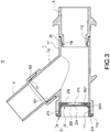
- the medical joint 10 includes a connection tube 1 and a check valve module 2.
- the check valve module 2 includes a first membrane 21 and a second membrane 22.
- connection tube 1 can be linear, Y-shaped, T-shaped, or of other suitable shape.
- connection tube 1 is a Y-shaped tube as an example; however, the present invention is not limited thereto.
- the connection tube 1 includes a first tube 11 and a second tube 12 extending from and communicating with the first tube 11.
- Two ends of the first tube 11 include a communicating opening 111 and a first junction 112 respectively.
- a distal end of the second tube 12 includes a second junction 121.
- An included angle ⁇ is formed between the first slit 211 and the second slit 221, and the included angle ⁇ ranges from 30 to 150 degrees. In the best embodiment, the included angle ⁇ is 90 degrees.
- the first tube 11 forms a rim 113 at the communicating opening 111.
- a wall of the first tube 11 is disposed with two vents 114 opposite to each other.
- a first engagement ring 115 extends from an inner wall surface of the first tube 11.
- the check valve module 2 is assembled to the communicating opening 111 to seal the same.
- the check valve module 2 includes a first membrane 21 and a second membrane 22 disposed overlappingly.
- the first membrane 21 includes a first slit 211
- the second membrane 22 includes a second slit 221
- the first slit 211 and the second slit 221 intersect each other.
- the first membrane 21 includes a first plate 212 and an annular wall 213 extending from a periphery of the first plate 212.
- the annular wall 213 forms a stop ring 214 extending outwardly from one end of the annular wall 213 disposed away from the first plate 212.
- the annular wall 213 is disposed with two through holes 215 opposite to each other.
- the first slit 211 is formed on the first plate 212.
- the annular wall 213 is inserted in the first tube 11 and contacts the same.
- the stop ring 214 and the rim 113 abut each other for securement therebetween.
- the second membrane 22 has a second plate 222 and two wings 223 extending from two sides of the second plate 222, a protrusion 224 extends from a distal end of each of the wings 223, the second slit 221 is formed on the second plate 222, the second plate 222 and the first plate 212 overlap and contact each other, the wings 223 pass through the respective through holes 215 and the respective vents 114 for securement, and the protrusion 224 and the first tube 11 engage each other.
- the first plate 212 includes a plurality of protruding points 2121 extending therefrom, the second plate 222 is disposed with a plurality of trenches 2221, the protruding points 2121 are engaged with the trenches 2221 respectively, thereby preventing the first plate 212 from moving or rotating with respect to the second plate 222, so as to secure the first plate 212 in position.
- the medical joint 10 further comprises a first rotatable tube 3 and a second rotatable tube 4, the first rotatable tube 3 is connected to the first junction 112 and rotatable with respect to the first tube 11, and the second rotatable tube 4 is connected to the second junction 121 and rotatable with respect to the second tube 12.
- a first annular recess 31 is formed on the exterior of the first rotatable tube 3, the first rotatable tube 3 is inserted in the first tube 11 via the first junction 112, the first engagement ring 115 is engaged with the first annular recess 31, and thereby the first rotatable tube 3 is rotatable with respect to the first tube 11.
- a second annular recess 122 is formed on the exterior of the second tube 12, a first engagement ring 41 extends from the interior of the second rotatable tube 4, one end of the second rotatable tube 4 encloses the second junction 121 of the second tube 12, and the first engagement ring 41 is engaged with the second annular recess 122, and thereby the second rotatable tube 4 is rotatable with respect to the second tube 12.
- first membrane 21 and the second membrane 22 consist of plastic, rubber, or other suitable materials.
- the first tube 11, the second tube 12, the first membrane 21, the second membrane 22, the first rotatable tube, or the second rotatable tube 4 can consist of or can be coated by an antibacterial material such as a silver-iron antibacterial material, so that the first tube 11, the second tube 12, the first membrane 21, the second membrane 22, the first rotatable tube 3, or the second rotatable tube 4 have an antibacterial property.
- the medical joint 10 of the present invention includes a connection tube 1 and the check valve module 2.
- the connection tube 1 includes a first tube 11 and a second tube 12 extending from and communicating with the first tube 11, two ends of the first tube 11 includes a communicating opening 111 and a first junction 112 respectively, and a distal end of the second tube 12 includes a second junction 121.
- the check valve module 2 is assembled to the communicating opening 111 to seal the same, the check valve module 2 includes a first membrane 21 and a second membrane 22 disposed overlappingly, the first membrane 21 includes a first slit 211, the second membrane 22 includes a second slit 221, and the first slit 211 and the second slit 221 intersect each other.
- the first membrane 21 and the second membrane 22 are disposed overlappingly, the second membrane 22 includes a second slit 221, and the first slit 211 and the second slit 221 intersect each other.
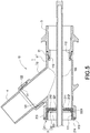
- Fig. 5 which illustrates a use state of the medical joint 10 and the check valve module 2
- the first membrane 21 is opened or closed via the first slit 211
- the second membrane 22 is opened or closed via the second slit 221, thereby facilitating inserting a detector into the connection tube 1 via an intersection of the first slit 211 and the second slit 221 so as to detect gas pressure, MDI, gas, temperature, or inserting a suction tube 100 to remove sputum.
- the first slit 211 and the second slit 221 intersect each other, so interference occurs between the open first membrane 21 and the open second membrane 22, thereby preventing the first membrane 21 and the second membrane 22 from opening too widely, thus avoiding a gas inside the connection tube 1 from leaking out from the intersection of the first slit 211 and the second slit 221, consequently achieving convenience and a gas-leak-proof property in using the medical joint 10 and the check valve module 2.
- the annular wall 213 is inserted in the first tube 11 and contacts the same, the stop ring 214 and the rim 113 abut each other for securement therebetween, the second plate 222 and the first plate 212 overlap and contact each other, the wings 223 pass through the respective through holes 215 and the respective vents 114 for securement, and the protrusion 224 and the first tube 11 engage each other, so that the first membrane 21 and the second membrane 22 are assembled securely to seal the communicating opening 111. Furthermore, the protruding points 2121 are engaged with the trenches 2221 respectively, thereby preventing the first plate 212 from moving or rotating with respect to the second plate 222, thus enhancing securement between the first membrane 21 and the second membrane 22.
- the medical joint 10 further includes a first rotatable tube 3 and a second rotatable tube 4, the first rotatable tube 3 is connected to the first junction 112 and rotatable with respect to the first tube 11, and the second rotatable tube 4 is connected to the second junction 121 and rotatable with respect to the second tube 12. Therefore, when the first rotatable tube 3 or the second rotatable tube 4 is connected to other external tubing, the position of the connection tube 1 is maintained even if inadvertently touching, moving or rotating the external tubing, thereby enhancing the safety in using the medical joint 10.
- Fig. 6 illustrates the medical joint according to another embodiment of the present invention.
- the embodiment in Fig. 6 is similar to the embodiment in Figs. 1 to 5 .
- the embodiment shown in Fig. 6 is different from the embodiment shown in Figs. 1 to 5 in that the first plate 212 and the second plate 222 are each a convex plate 23 protruding in a direction away from the communicating opening 111.
- the first plate 212 and the second plate 222 are each a convex plate 23 protruding in a direction away from the communicating opening 111, so when the detector or the suction tube is inserted into the connection tube 1 via the communicating opening 111, the first slit 211 and the second slit 221 are opened toward the same direction as the inserting direction of the detector or the suction tube, thereby guiding the detector or the suction tube to be readily inserted into the communicating opening, so as to promote convenience in using the medical joint 10 and the check valve module 2.
- Each convex plate 23 can be a plano-convex plate or a concavo-convex plate. In the present embodiment, each convex plate 23 is a concavo-convex plate; however, the present invention is not limited thereto.
Landscapes
- Health & Medical Sciences (AREA)
- Pulmonology (AREA)
- Emergency Medicine (AREA)
- Engineering & Computer Science (AREA)
- Anesthesiology (AREA)
- Biomedical Technology (AREA)
- Heart & Thoracic Surgery (AREA)
- Hematology (AREA)
- Life Sciences & Earth Sciences (AREA)
- Animal Behavior & Ethology (AREA)
- General Health & Medical Sciences (AREA)
- Public Health (AREA)
- Veterinary Medicine (AREA)
- Infusion, Injection, And Reservoir Apparatuses (AREA)
- External Artificial Organs (AREA)
Claims (7)
- Medizinische Verbindung, umfassend:ein Verbindungsrohr (1), das ein erstes Rohr (11) und ein zweites Rohr (12) aufweist, das sich ausgehend von dem ersten Rohr (11) erstreckt und mit diesem kommuniziert, wobei zwei Enden des ersten Rohres (11) eine kommunizierende Öffnung (111) bzw. einen ersten Anschluss (112) aufweisen, wobei ein distales Ende des zweiten Rohres (12) einen zweiten Anschluss (121) aufweist; undein Rückschlagventilmodul (2), das an die kommunizierende Öffnung (111) angebaut ist, um diese abzudichten, wobei das Rückschlagventilmodul (2) eine erste Membran (21) und eine zweite Membran (22) aufweist, die überlappend angeordnet sind, wobei die erste Membran (21) einen ersten Schlitz (211) aufweist und die zweite Membran (22) einen zweiten Schlitz (221) aufweist;wobei der erste Schlitz (211) und der zweite Schlitz (221) einander kreuzen,dadurch gekennzeichnet, dass das erste Rohr (11) einen Kranz (113) an der kommunizierenden Öffnung (111) bildet, die erste Membran (21) eine erste Platte (212) und eine ringförmige Wand (213) aufweist, die sich ausgehend von einem Umfang der ersten Platte (212) erstreckt, die ringförmige Wand (213) einen Stoppring (214) bildet, der sich, von der ersten Platte (212) weggewandt angeordnet, von einem Ende der ringförmigen Wand (213) nach außen erstreckt, der erste Schlitz (211) in der ersten Platte (212) gebildet ist, die ringförmige Wand (213) in das erste Rohr (11) eingefügt ist und dieses berührt, der Stoppring (214) und der Kranz (113) für eine feste Verbindung zwischen ihnen aneinander anliegen, das erste Rohr (11) zwei Lüftungsöffnungen (114) aufweist, die einander gegenüberliegen, die ringförmige Wand (213) zwei Durchgangslöcher (215) aufweist, die einander gegenüberliegen, die zweite Membran (22) eine zweite Platte (222) und zwei Flügel (223) aufweist, die sich ausgehend von zwei Seiten der zweiten Platte (222) erstrecken, ein Vorsprung (224) sich ausgehend von einem distalen Ende von jedem der Flügel (223) erstreckt, der zweite Schlitz (221) in der zweiten Platte (222) gebildet ist, die zweite Platte (222) und die erste Platte (212) einander überlappen und berühren, die Flügel (223) zur Befestigung durch die jeweiligen Durchgangslöcher (215) und die jeweiligen Lüftungsöffnungen (114) hindurchgehen und der Vorsprung (224) und das erste Rohr (11) miteinander in Eingriff sind.
- Medizinische Verbindung nach Anspruch 1, wobei ein eingeschlossener Winkel (θ) zwischen dem ersten Schlitz (211) und dem zweiten Schlitz (221) gebildet ist und der eingeschlossene Winkel (θ) 30 Grad bis 150 Grad beträgt.
- Medizinische Verbindung nach Anspruch 1, wobei ein eingeschlossener Winkel (θ) zwischen dem ersten Schlitz (211) und dem zweiten Schlitz (221) gebildet ist und der eingeschlossene Winkel (θ) 90 Grad beträgt.
- Medizinische Verbindung nach Anspruch 1, wobei das Verbindungsrohr (1) ein Y-förmiges Rohr oder ein T-förmiges Rohr ist.
- Medizinische Verbindung nach Anspruch 1, wobei die erste Platte (212) eine Vielzahl von vorragenden Punkten (2121) aufweist, die sich ausgehend von ihr erstrecken, die zweite Platte (222) mit einer Vielzahl von Kerben (2221) versehen ist, die vorragenden Punkte (2121) jeweils in Eingriff mit den Kerben (2221) sind und die erste Platte (212) und die zweite Platte (222) jeweils eine konvexe Platte (23) sind, die in einer Richtung weg von der kommunizierenden Öffnung (111) vorragt.
- Medizinische Verbindung nach Anspruch 1, ferner umfassend ein erstes drehbares Rohr (3) und ein zweites drehbares Rohr (4), wobei das erste drehbare Rohr (3) mit dem ersten Anschluss (112) verbunden ist und in Bezug auf das erste Rohr (11) drehbar ist, und wobei das zweite drehbare Rohr (4) mit dem zweiten Anschluss (121) verbunden ist und in Bezug auf das zweite Rohr (12) drehbar ist.
- Medizinische Verbindung nach Anspruch 6, wobei ein erster Eingriffring (115) sich ausgehend von der Innenseite des ersten Rohres (11) erstreckt, eine erste ringförmige Vertiefung (31) an der Außenseite des ersten drehbaren Rohres (3) gebildet ist, das erste drehbare Rohr (3) durch den ersten Anschluss (112) in das erste Rohr (11) eingefügt ist, der erste Eingriffring (115) mit der ersten ringförmigen Vertiefung (31) in Eingriff ist, eine zweite ringförmige Vertiefung (122) an der Außenseite des zweiten Rohres (12) gebildet ist, ein erster Eingriffring (41) sich ausgehend von der Innenseite des zweiten drehbaren Rohres (4) erstreckt, ein Ende des zweiten drehbaren Rohres (4) den zweiten Anschluss (121) des zweiten Rohres (12) umschließt und der erste Eingriffring (41) mit der zweiten ringförmigen Vertiefung (122) in Eingriff ist.
Priority Applications (1)
| Application Number | Priority Date | Filing Date | Title |
|---|---|---|---|
| EP15184923.9A EP3141277B1 (de) | 2015-09-11 | 2015-09-11 | Medizinische verbindung und rückschlagventilmodul dafür |
Applications Claiming Priority (1)
| Application Number | Priority Date | Filing Date | Title |
|---|---|---|---|
| EP15184923.9A EP3141277B1 (de) | 2015-09-11 | 2015-09-11 | Medizinische verbindung und rückschlagventilmodul dafür |
Publications (2)
| Publication Number | Publication Date |
|---|---|
| EP3141277A1 EP3141277A1 (de) | 2017-03-15 |
| EP3141277B1 true EP3141277B1 (de) | 2017-08-02 |
Family
ID=54106274
Family Applications (1)
| Application Number | Title | Priority Date | Filing Date |
|---|---|---|---|
| EP15184923.9A Not-in-force EP3141277B1 (de) | 2015-09-11 | 2015-09-11 | Medizinische verbindung und rückschlagventilmodul dafür |
Country Status (1)
| Country | Link |
|---|---|
| EP (1) | EP3141277B1 (de) |
Cited By (1)
| Publication number | Priority date | Publication date | Assignee | Title |
|---|---|---|---|---|
| TWI773578B (zh) * | 2021-11-05 | 2022-08-01 | 佛教慈濟醫療財團法人 | 呼吸器面罩多功能結構 |
Families Citing this family (2)
| Publication number | Priority date | Publication date | Assignee | Title |
|---|---|---|---|---|
| DE102018113154A1 (de) * | 2018-06-01 | 2019-12-05 | Ventinova Technologies B.V. | Endotrachealtubusadapter |
| CN108721744B (zh) * | 2018-06-14 | 2021-05-18 | 深圳市华医安全医疗科技有限公司 | 一种静音式呼吸机 |
Family Cites Families (4)
| Publication number | Priority date | Publication date | Assignee | Title |
|---|---|---|---|---|
| DE50101193D1 (de) * | 2001-06-19 | 2004-01-29 | Storz Karl Gmbh & Co Kg | Zugangskanüle für endoskopische Operationen, insbesondere für die Arthroskopie |
| US7036509B2 (en) * | 2003-12-04 | 2006-05-02 | Emphasys Medical, Inc. | Multiple seal port anesthesia adapter |
| AU2009276568B2 (en) * | 2008-07-29 | 2015-04-23 | Carefusion 207, Inc. | Valve assembly for respiratory systems |
| DE102011088337A1 (de) * | 2011-12-13 | 2013-06-13 | Karl Storz Gmbh & Co. Kg | Dichteinrichtung zur Abdichtung einer Durchführung für ein medizinisches Instrument |
-
2015
- 2015-09-11 EP EP15184923.9A patent/EP3141277B1/de not_active Not-in-force
Non-Patent Citations (1)
| Title |
|---|
| None * |
Cited By (1)
| Publication number | Priority date | Publication date | Assignee | Title |
|---|---|---|---|---|
| TWI773578B (zh) * | 2021-11-05 | 2022-08-01 | 佛教慈濟醫療財團法人 | 呼吸器面罩多功能結構 |
Also Published As
| Publication number | Publication date |
|---|---|
| EP3141277A1 (de) | 2017-03-15 |
Similar Documents
| Publication | Publication Date | Title |
|---|---|---|
| US10086164B2 (en) | Medical joint and check valve module thereof | |
| US8002750B2 (en) | Access apparatus with shallow zero closure valve | |
| JP5919588B2 (ja) | 呼吸器具のための迅速継手 | |
| US11540821B2 (en) | Surgical access device including gimbal mount cooperating with bellows | |
| EP3383478B1 (de) | Flexible kappe für konische verbinder | |
| BRPI0609131A2 (pt) | conjunto compreendendo cateter e peça de conexão, e válvula para a passagem de um cateter | |
| MX2011005648A (es) | Ensamble de puerto de acceso respiratorio con un cierre de boton de presion. | |
| EP3141277B1 (de) | Medizinische verbindung und rückschlagventilmodul dafür | |
| US11911010B2 (en) | Medical instrument port for use with protective face coverings | |
| JP2012511376A (ja) | 医用換気・吸引器具のためのポート密閉カートリッジ | |
| US8544463B2 (en) | Overmolded manifold O-ring | |
| US11504493B2 (en) | Curved connection unit for connecting a patient to a medical device | |
| US20240198077A1 (en) | Barbed Stopcock and Securement Clips for Medical Tubing | |
| MX2014007298A (es) | Ensamble de freno de acoplamiento para un orificio de acceso respiratorio. | |
| US20240081937A1 (en) | Adjustable seal for fluid management system | |
| CN203861722U (zh) | 多功能气管导管衔接管 | |
| ITRM20110170A1 (it) | Dispositivo di tenuta a labbro per trocar e relativo trocar. |
Legal Events
| Date | Code | Title | Description |
|---|---|---|---|
| PUAI | Public reference made under article 153(3) epc to a published international application that has entered the european phase |
Free format text: ORIGINAL CODE: 0009012 |
|
| 17P | Request for examination filed |
Effective date: 20160519 |
|
| AK | Designated contracting states |
Kind code of ref document: A1 Designated state(s): AL AT BE BG CH CY CZ DE DK EE ES FI FR GB GR HR HU IE IS IT LI LT LU LV MC MK MT NL NO PL PT RO RS SE SI SK SM TR |
|
| AX | Request for extension of the european patent |
Extension state: BA ME |
|
| GRAP | Despatch of communication of intention to grant a patent |
Free format text: ORIGINAL CODE: EPIDOSNIGR1 |
|
| RIC1 | Information provided on ipc code assigned before grant |
Ipc: A61M 16/04 20060101ALI20170313BHEP Ipc: A61M 16/20 20060101ALI20170313BHEP Ipc: A61M 16/08 20060101AFI20170313BHEP Ipc: A61M 39/24 20060101ALN20170313BHEP Ipc: A61M 39/06 20060101ALN20170313BHEP |
|
| INTG | Intention to grant announced |
Effective date: 20170404 |
|
| RAP1 | Party data changed (applicant data changed or rights of an application transferred) |
Owner name: CHEN, JIUNN-RONG Owner name: CHOU, JENG-YU |
|
| GRAS | Grant fee paid |
Free format text: ORIGINAL CODE: EPIDOSNIGR3 |
|
| GRAA | (expected) grant |
Free format text: ORIGINAL CODE: 0009210 |
|
| AK | Designated contracting states |
Kind code of ref document: B1 Designated state(s): AL AT BE BG CH CY CZ DE DK EE ES FI FR GB GR HR HU IE IS IT LI LT LU LV MC MK MT NL NO PL PT RO RS SE SI SK SM TR |
|
| REG | Reference to a national code |
Ref country code: CH Ref legal event code: EP Ref country code: AT Ref legal event code: REF Ref document number: 913794 Country of ref document: AT Kind code of ref document: T Effective date: 20170815 |
|
| REG | Reference to a national code |
Ref country code: IE Ref legal event code: FG4D |
|
| REG | Reference to a national code |
Ref country code: NL Ref legal event code: FP |
|
| REG | Reference to a national code |
Ref country code: DE Ref legal event code: R096 Ref document number: 602015003849 Country of ref document: DE |
|
| REG | Reference to a national code |
Ref country code: AT Ref legal event code: MK05 Ref document number: 913794 Country of ref document: AT Kind code of ref document: T Effective date: 20170802 |
|
| REG | Reference to a national code |
Ref country code: LT Ref legal event code: MG4D |
|
| PG25 | Lapsed in a contracting state [announced via postgrant information from national office to epo] |
Ref country code: SE Free format text: LAPSE BECAUSE OF FAILURE TO SUBMIT A TRANSLATION OF THE DESCRIPTION OR TO PAY THE FEE WITHIN THE PRESCRIBED TIME-LIMIT Effective date: 20170802 Ref country code: LT Free format text: LAPSE BECAUSE OF FAILURE TO SUBMIT A TRANSLATION OF THE DESCRIPTION OR TO PAY THE FEE WITHIN THE PRESCRIBED TIME-LIMIT Effective date: 20170802 Ref country code: AT Free format text: LAPSE BECAUSE OF FAILURE TO SUBMIT A TRANSLATION OF THE DESCRIPTION OR TO PAY THE FEE WITHIN THE PRESCRIBED TIME-LIMIT Effective date: 20170802 Ref country code: HR Free format text: LAPSE BECAUSE OF FAILURE TO SUBMIT A TRANSLATION OF THE DESCRIPTION OR TO PAY THE FEE WITHIN THE PRESCRIBED TIME-LIMIT Effective date: 20170802 Ref country code: NO Free format text: LAPSE BECAUSE OF FAILURE TO SUBMIT A TRANSLATION OF THE DESCRIPTION OR TO PAY THE FEE WITHIN THE PRESCRIBED TIME-LIMIT Effective date: 20171102 Ref country code: FI Free format text: LAPSE BECAUSE OF FAILURE TO SUBMIT A TRANSLATION OF THE DESCRIPTION OR TO PAY THE FEE WITHIN THE PRESCRIBED TIME-LIMIT Effective date: 20170802 |
|
| PG25 | Lapsed in a contracting state [announced via postgrant information from national office to epo] |
Ref country code: IS Free format text: LAPSE BECAUSE OF FAILURE TO SUBMIT A TRANSLATION OF THE DESCRIPTION OR TO PAY THE FEE WITHIN THE PRESCRIBED TIME-LIMIT Effective date: 20171202 Ref country code: RS Free format text: LAPSE BECAUSE OF FAILURE TO SUBMIT A TRANSLATION OF THE DESCRIPTION OR TO PAY THE FEE WITHIN THE PRESCRIBED TIME-LIMIT Effective date: 20170802 Ref country code: PL Free format text: LAPSE BECAUSE OF FAILURE TO SUBMIT A TRANSLATION OF THE DESCRIPTION OR TO PAY THE FEE WITHIN THE PRESCRIBED TIME-LIMIT Effective date: 20170802 Ref country code: ES Free format text: LAPSE BECAUSE OF FAILURE TO SUBMIT A TRANSLATION OF THE DESCRIPTION OR TO PAY THE FEE WITHIN THE PRESCRIBED TIME-LIMIT Effective date: 20170802 Ref country code: LV Free format text: LAPSE BECAUSE OF FAILURE TO SUBMIT A TRANSLATION OF THE DESCRIPTION OR TO PAY THE FEE WITHIN THE PRESCRIBED TIME-LIMIT Effective date: 20170802 Ref country code: BG Free format text: LAPSE BECAUSE OF FAILURE TO SUBMIT A TRANSLATION OF THE DESCRIPTION OR TO PAY THE FEE WITHIN THE PRESCRIBED TIME-LIMIT Effective date: 20171102 Ref country code: GR Free format text: LAPSE BECAUSE OF FAILURE TO SUBMIT A TRANSLATION OF THE DESCRIPTION OR TO PAY THE FEE WITHIN THE PRESCRIBED TIME-LIMIT Effective date: 20171103 |
|
| PG25 | Lapsed in a contracting state [announced via postgrant information from national office to epo] |
Ref country code: CZ Free format text: LAPSE BECAUSE OF FAILURE TO SUBMIT A TRANSLATION OF THE DESCRIPTION OR TO PAY THE FEE WITHIN THE PRESCRIBED TIME-LIMIT Effective date: 20170802 Ref country code: DK Free format text: LAPSE BECAUSE OF FAILURE TO SUBMIT A TRANSLATION OF THE DESCRIPTION OR TO PAY THE FEE WITHIN THE PRESCRIBED TIME-LIMIT Effective date: 20170802 |
|
| REG | Reference to a national code |
Ref country code: DE Ref legal event code: R097 Ref document number: 602015003849 Country of ref document: DE |
|
| PG25 | Lapsed in a contracting state [announced via postgrant information from national office to epo] |
Ref country code: SK Free format text: LAPSE BECAUSE OF FAILURE TO SUBMIT A TRANSLATION OF THE DESCRIPTION OR TO PAY THE FEE WITHIN THE PRESCRIBED TIME-LIMIT Effective date: 20170802 Ref country code: SM Free format text: LAPSE BECAUSE OF FAILURE TO SUBMIT A TRANSLATION OF THE DESCRIPTION OR TO PAY THE FEE WITHIN THE PRESCRIBED TIME-LIMIT Effective date: 20170802 Ref country code: EE Free format text: LAPSE BECAUSE OF FAILURE TO SUBMIT A TRANSLATION OF THE DESCRIPTION OR TO PAY THE FEE WITHIN THE PRESCRIBED TIME-LIMIT Effective date: 20170802 Ref country code: IT Free format text: LAPSE BECAUSE OF FAILURE TO SUBMIT A TRANSLATION OF THE DESCRIPTION OR TO PAY THE FEE WITHIN THE PRESCRIBED TIME-LIMIT Effective date: 20170802 Ref country code: MC Free format text: LAPSE BECAUSE OF FAILURE TO SUBMIT A TRANSLATION OF THE DESCRIPTION OR TO PAY THE FEE WITHIN THE PRESCRIBED TIME-LIMIT Effective date: 20170802 |
|
| PLBE | No opposition filed within time limit |
Free format text: ORIGINAL CODE: 0009261 |
|
| STAA | Information on the status of an ep patent application or granted ep patent |
Free format text: STATUS: NO OPPOSITION FILED WITHIN TIME LIMIT |
|
| REG | Reference to a national code |
Ref country code: IE Ref legal event code: MM4A |
|
| REG | Reference to a national code |
Ref country code: BE Ref legal event code: MM Effective date: 20170930 |
|
| PG25 | Lapsed in a contracting state [announced via postgrant information from national office to epo] |
Ref country code: LU Free format text: LAPSE BECAUSE OF NON-PAYMENT OF DUE FEES Effective date: 20170911 |
|
| REG | Reference to a national code |
Ref country code: FR Ref legal event code: ST Effective date: 20180531 |
|
| 26N | No opposition filed |
Effective date: 20180503 |
|
| PG25 | Lapsed in a contracting state [announced via postgrant information from national office to epo] |
Ref country code: IE Free format text: LAPSE BECAUSE OF NON-PAYMENT OF DUE FEES Effective date: 20170911 |
|
| PG25 | Lapsed in a contracting state [announced via postgrant information from national office to epo] |
Ref country code: FR Free format text: LAPSE BECAUSE OF NON-PAYMENT OF DUE FEES Effective date: 20171002 Ref country code: SI Free format text: LAPSE BECAUSE OF FAILURE TO SUBMIT A TRANSLATION OF THE DESCRIPTION OR TO PAY THE FEE WITHIN THE PRESCRIBED TIME-LIMIT Effective date: 20170802 Ref country code: BE Free format text: LAPSE BECAUSE OF NON-PAYMENT OF DUE FEES Effective date: 20170930 |
|
| PG25 | Lapsed in a contracting state [announced via postgrant information from national office to epo] |
Ref country code: MT Free format text: LAPSE BECAUSE OF NON-PAYMENT OF DUE FEES Effective date: 20170911 |
|
| PGFP | Annual fee paid to national office [announced via postgrant information from national office to epo] |
Ref country code: DE Payment date: 20180827 Year of fee payment: 4 |
|
| PGFP | Annual fee paid to national office [announced via postgrant information from national office to epo] |
Ref country code: NL Payment date: 20180919 Year of fee payment: 4 |
|
| REG | Reference to a national code |
Ref country code: CH Ref legal event code: PL |
|
| PG25 | Lapsed in a contracting state [announced via postgrant information from national office to epo] |
Ref country code: HU Free format text: LAPSE BECAUSE OF FAILURE TO SUBMIT A TRANSLATION OF THE DESCRIPTION OR TO PAY THE FEE WITHIN THE PRESCRIBED TIME-LIMIT; INVALID AB INITIO Effective date: 20150911 |
|
| PG25 | Lapsed in a contracting state [announced via postgrant information from national office to epo] |
Ref country code: CH Free format text: LAPSE BECAUSE OF NON-PAYMENT OF DUE FEES Effective date: 20180930 Ref country code: RO Free format text: LAPSE BECAUSE OF FAILURE TO SUBMIT A TRANSLATION OF THE DESCRIPTION OR TO PAY THE FEE WITHIN THE PRESCRIBED TIME-LIMIT Effective date: 20170802 Ref country code: LI Free format text: LAPSE BECAUSE OF NON-PAYMENT OF DUE FEES Effective date: 20180930 |
|
| PG25 | Lapsed in a contracting state [announced via postgrant information from national office to epo] |
Ref country code: CY Free format text: LAPSE BECAUSE OF FAILURE TO SUBMIT A TRANSLATION OF THE DESCRIPTION OR TO PAY THE FEE WITHIN THE PRESCRIBED TIME-LIMIT Effective date: 20170802 |
|
| PG25 | Lapsed in a contracting state [announced via postgrant information from national office to epo] |
Ref country code: MK Free format text: LAPSE BECAUSE OF FAILURE TO SUBMIT A TRANSLATION OF THE DESCRIPTION OR TO PAY THE FEE WITHIN THE PRESCRIBED TIME-LIMIT Effective date: 20170802 |
|
| PG25 | Lapsed in a contracting state [announced via postgrant information from national office to epo] |
Ref country code: TR Free format text: LAPSE BECAUSE OF FAILURE TO SUBMIT A TRANSLATION OF THE DESCRIPTION OR TO PAY THE FEE WITHIN THE PRESCRIBED TIME-LIMIT Effective date: 20170802 |
|
| REG | Reference to a national code |
Ref country code: DE Ref legal event code: R119 Ref document number: 602015003849 Country of ref document: DE |
|
| REG | Reference to a national code |
Ref country code: NL Ref legal event code: MM Effective date: 20191001 |
|
| PG25 | Lapsed in a contracting state [announced via postgrant information from national office to epo] |
Ref country code: PT Free format text: LAPSE BECAUSE OF FAILURE TO SUBMIT A TRANSLATION OF THE DESCRIPTION OR TO PAY THE FEE WITHIN THE PRESCRIBED TIME-LIMIT Effective date: 20170802 |
|
| PG25 | Lapsed in a contracting state [announced via postgrant information from national office to epo] |
Ref country code: DE Free format text: LAPSE BECAUSE OF NON-PAYMENT OF DUE FEES Effective date: 20200401 Ref country code: NL Free format text: LAPSE BECAUSE OF NON-PAYMENT OF DUE FEES Effective date: 20191001 Ref country code: AL Free format text: LAPSE BECAUSE OF FAILURE TO SUBMIT A TRANSLATION OF THE DESCRIPTION OR TO PAY THE FEE WITHIN THE PRESCRIBED TIME-LIMIT Effective date: 20170802 |
|
| GBPC | Gb: european patent ceased through non-payment of renewal fee |
Effective date: 20190911 |
|
| PG25 | Lapsed in a contracting state [announced via postgrant information from national office to epo] |
Ref country code: GB Free format text: LAPSE BECAUSE OF NON-PAYMENT OF DUE FEES Effective date: 20190911 |