EP3141306B1 - Extracteur avec système segmenté d'écoulement d'air sous pression positif - Google Patents
Extracteur avec système segmenté d'écoulement d'air sous pression positif Download PDFInfo
- Publication number
- EP3141306B1 EP3141306B1 EP16169433.6A EP16169433A EP3141306B1 EP 3141306 B1 EP3141306 B1 EP 3141306B1 EP 16169433 A EP16169433 A EP 16169433A EP 3141306 B1 EP3141306 B1 EP 3141306B1
- Authority
- EP
- European Patent Office
- Prior art keywords
- positive pressure
- gas stream
- pressure gas
- negative pressure
- manifold
- Prior art date
- Legal status (The legal status is an assumption and is not a legal conclusion. Google has not performed a legal analysis and makes no representation as to the accuracy of the status listed.)
- Active
Links
Images







Classifications
-
- F—MECHANICAL ENGINEERING; LIGHTING; HEATING; WEAPONS; BLASTING
- F24—HEATING; RANGES; VENTILATING
- F24F—AIR-CONDITIONING; AIR-HUMIDIFICATION; VENTILATION; USE OF AIR CURRENTS FOR SCREENING
- F24F7/00—Ventilation
- F24F7/02—Roof ventilation
- F24F7/025—Roof ventilation with forced air circulation by means of a built-in ventilator
-
- B—PERFORMING OPERATIONS; TRANSPORTING
- B08—CLEANING
- B08B—CLEANING IN GENERAL; PREVENTION OF FOULING IN GENERAL
- B08B15/00—Preventing escape of dirt or fumes from the area where they are produced; Collecting or removing dirt or fumes from that area
- B08B15/002—Preventing escape of dirt or fumes from the area where they are produced; Collecting or removing dirt or fumes from that area using a central suction system, e.g. for collecting exhaust gases in workshops
-
- B—PERFORMING OPERATIONS; TRANSPORTING
- B08—CLEANING
- B08B—CLEANING IN GENERAL; PREVENTION OF FOULING IN GENERAL
- B08B15/00—Preventing escape of dirt or fumes from the area where they are produced; Collecting or removing dirt or fumes from that area
-
- B—PERFORMING OPERATIONS; TRANSPORTING
- B08—CLEANING
- B08B—CLEANING IN GENERAL; PREVENTION OF FOULING IN GENERAL
- B08B15/00—Preventing escape of dirt or fumes from the area where they are produced; Collecting or removing dirt or fumes from that area
- B08B15/02—Preventing escape of dirt or fumes from the area where they are produced; Collecting or removing dirt or fumes from that area using chambers or hoods covering the area
-
- B—PERFORMING OPERATIONS; TRANSPORTING
- B23—MACHINE TOOLS; METAL-WORKING NOT OTHERWISE PROVIDED FOR
- B23K—SOLDERING OR UNSOLDERING; WELDING; CLADDING OR PLATING BY SOLDERING OR WELDING; CUTTING BY APPLYING HEAT LOCALLY, e.g. FLAME CUTTING; WORKING BY LASER BEAM
- B23K9/00—Arc welding or cutting
- B23K9/32—Accessories
- B23K9/325—Devices for supplying or evacuating shielding gas
Definitions
- the present disclosure relates generally to systems for extracting fumes or airborne components from air streams, such as in welding, cutting, metal working, wood working, and other applications.
- the extractor hood comprises an extraction conduit and a delivery conduit, the first one housing an air treatment unit that extracts air through the lower mouth of the same conduit, and the second one housing an air treatment unit that produces a forced air flow with inside-outside direction, which is suitably conveyed by a deflector with downward inclination to generate a pneumatic screen above the cook top that conveys fumes rising from the cook top towards the lower mouth of the extraction conduit.
- US 2013/244 448 A1 shows a further extraction system designed for metal working and other applications.
- the system may comprise a cart-type base or may be incorporated into a fixed or semi-fixed installation.
- a blower delivers a positive pressure airflow to a hood that creates an air region by directing the air through an annular space between inner and outer shrouds, impacting the air against a single generally perpendicular flange.
- Return air from the operation may be mixed with fresh air, both of which may be filtered, to supply the positive pressure air. Both air streams to and from the hood may be adjusted to optimize operation. Adjustments may be made at the base unit or remotely.
- JP 2008 070049 A describes a range hood arranged above a heating cooking apparatus, and it has a suction opening arranged facing the heating cooking apparatus and sucking in air, and a discharge opening discharging air forming the air curtain circumferentially extending around at least one portion of the suction opening, and heading toward a heating cooking apparatus side.
- a discharge state control means is provided for controlling air forming the air curtain into a state such that the air curtain is extended until a heating cooking apparatus neighborhood so as to carry out blocking, and it is not influenced by a suction air flow in response to an air capacity sucked in from the suction opening.
- a wide range of industrial, commercial, hobby and other applications result in airborne components that can be removed with proper extraction and filtering.
- Metal working operations for example, including cutting, welding, soldering, assembly, and other processes may generate smoke, particulate, and fumes.
- cart-type fume extractors are used.
- more complex fixed systems may be employed for extracting fumes from specific works cells, metal working locations, and so forth.
- dust, fumes, particulate and other types of airborne components may be generated that it may be desirable to collect and extract from work areas and controlled spaces.
- a number of systems have been developed for fume extraction, and a certain number of these are currently in use. Some of these systems use negative pressure air to draw fumes and smoke from the immediate vicinity of the metal working operation, and to filter the fumes and smoke before returning the air to the room or blowing the air to an outside space. Other systems may use a combination of negative pressure zones (e.g., suction air) and positive pressure zones. Further improvements are needed, however, in fume extraction systems. For example, it would be useful to increase the flexibility and the effective ability of the systems to draw the fumes and smoke from a wide range of workspaces or locations within the workspace.
- the present invention refers to an extractor system as defined in claim 1 and to a method as defined in claim 8. Further features of the present invention are included in the subclaims.
- FIG. 1 illustrates one embodiment of a fume extraction system 10 being used during a welding operation.
- welding is merely an example and that a wide range of industrial, commercial, hobby and other applications may result in fumes, smoke, or other airborne components that can be removed by the extraction system 10.
- Metal working operations for example, cutting, welding, soldering, assembly, and other processes may generate smoke, particulate, and fumes.
- dust, fumes, particulate and other types of airborne components may be generated that it may be desirable to collect and extract from work areas and controlled spaces.
- the extraction system 10 is placed in the work area 12 (e.g., work cell), in the vicinity of (e.g., above) the work surface 14.
- a user 16 e.g., a welder
- a work operation e.g., a welding operation
- a tool 20 e.g., welding torch
- the extraction system 10 may draw fumes and smoke from the work area 12.
- the user may utilize a helmet 22 (e.g., welding helmet) or other protective headwear, which may include one or more sensors 24.
- the one or more sensors 24 may be configured to sense one or more parameters indicative of the working environment or other parameters related to the work operation (e.g., fumes, temperature, humidity, light, motion, etc.).
- airborne components may include any substance that is borne by, suspended in or otherwise carried by the air, or more generally the fluid present in the area considered.
- the airborne components may be in an aerosol form, such as solid, liquid or gaseous phase particles that are suspended in air.
- Such airborne components may form smoke, fumes (including chemical fumes), or clouds present or given off by an operation ongoing in the area, whether or not visible to the human operators.
- a number of systems have been developed for fume extraction, some of which are currently in use. Some of these systems use negative pressure air to draw fumes and smoke from the immediate vicinity of the metal working operation, and to filter the fumes and smoke before returning the air to the work area 12 or blowing the air to an outside space. Other systems may use a combination of negative pressure zones (e.g., suction air) and positive pressure zones. Improvements to the ability to control the positive pressure gas stream (e.g., the direction of the gas stream, the flow rate of the air, etc.) may improve the effectiveness of the extraction system and the versatility of the extraction system to be used in a variety of different workspaces and configurations. Furthermore, the disclosed techniques may be used to retrofit existing extraction systems that only use a negative pressure zone (e.g., suction air).
- a negative pressure zone e.g., suction air
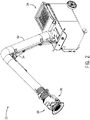
- FIG. 2 is a perspective view of an embodiment of the extraction system 10 in a mobile cart-type configuration.
- the extraction system 10 may include a suction cart 28, an arm 30, support bracketry 34, and a positive pressure head 36.
- the extraction system 10 may be provided as a complete system, as a replacement arm 30 and pressure head 36, the positive pressure head 36 by itself, or some combination thereof separately as an add-on or retrofit kit.
- the system may or may not include support bracketry 34 which may help the arm 30 to support the weight of the pressure head 36.
- the suction cart 28 provides negative pressure to draw the smoke, fumes, or airborne components away from the work area 12.
- the suction cart 28 may expel the air it draws in to an exhaust duct, out a window, an open door, or some other place outside of the work cell 12.
- the suction cart 28 may include a filtration system.
- the filtration system may be configured to filter the air drawn into the suction cart 28 before expelling the air to a location outside the work cell 12, or the filtration system may release the filtered air back into the work cell 12.
- the arm 30, which is a hollow tube, may be connected to the suction cart.
- the arm 30 may be a typical extraction arm, typically 8 or 10 inches in diameter, but may be of another size.
- the suction cart 28 draws air into the end 32 of the arm and through the arm 30, creating a negative pressure zone at the end 32 of the arm 30 opposite the suction cart 28, allowing the user 16 the ability to apply negative pressure to specific areas within the work cell 12.
- the support bracketry 34 may be attached to the arm 30 and assist in positioning and/or support the load of the arm 30.
- the positive pressure head 36 is attached to the end 32 of the arm 30 and may be configured to blow air radially outward, creating a positive pressure zone at the end of the arm 30.
- a positive pressure zone may improve the ability of the extraction system 10 to draw smoke, fumes, and airborne components into the arm 30.
- the specifics of the positive pressure head 36 and the positive pressure zone will be discuss in more detail with regard to FIGS. 11 and 12 .
- FIG. 3 is a perspective view of an embodiment of the extraction system 10 in a stationary floor-mounted or wall-mounted configuration.
- the extraction system 10 shown in FIG. 3 is similar to that shown in FIG. 2 , except that the negative pressure is provided by a stationary negative pressure system 38 rather than a suction cart 28.
- the extraction system 10 includes an extraction arm 30 coupled to the stationary negative pressure system 38.
- the extraction system 10 may be provided as a complete system, as a replacement arm 30 and pressure head 36, the positive pressure head 36 by itself, or some combination thereof separately as an add-on or retrofit kit.
- the system may or may not include support bracketry 34 which may help the arm 30 to support the weight of the pressure head 36.
- the user may move the arm 30 to position the end 32 of the arm 30 in the work area 12.
- a positive pressure head 36 is disposed on the end of the arm 30 and is configured to blow air in order to create a positive pressure zone and improve the performance of the extraction system 10 relative to a system that only uses negative pressure.
- the arm 30 may be outfitted with support bracketry 34 in order to support the cantilevered load of the positive pressure head 36 and the arm 30, and to help the user 16 position the arm.
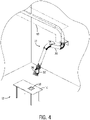
- FIG. 4 is a perspective view of an embodiment of the extraction system 10 in a ducted configuration.
- the extraction system 10 shown in FIG. 4 is similar to that shown in FIGS. 2 and 3 , except that the negative pressure is provided by a ducted negative pressure system 40 rather than a suction cart 28 or a stationary negative pressure system 38.
- the extraction system 10 may be provided as a complete system, as a replacement arm 30 and pressure head 36, the positive pressure head 36 by itself, or some combination thereof separately as an add-on or retrofit kit.
- the system may or may not include support bracketry 34 which may help the arm 30 to support the weight of the pressure head 36.
- the ducted negative pressure system 40 may be configured to draw air out of the various work cells 12 and expel the air outside or recirculate the air throughout the work cells. The air may be filtered before being recirculated or expelled.
- the extraction system 10 includes an arm 30 coupled to the stationary negative pressure system 38. The user may move the arm 30 to position the end 32 of the arm 30 in the vicinity of the work surface 14.
- a positive pressure head 36 is disposed on the end of the arm and is configured to blow air in order to create a positive pressure zone and improve the performance of the extraction system 10 relative to a system that only uses negative pressure.
- the arm 30 may be outfitted with support bracketry 34 in order to support the cantilevered load of the positive pressure head 36 and the arm 30, and to help the user 16 position the arm.
- FIG. 5 is a schematic of the extraction system 10 illustrating the negative pressure system 60 for extracting workspace air as indicated by reference numeral 62 from a work area 12. It should be understood, however, that this is merely an example and that the positive pressure head may also me mounted to a "push-pull" system that uses both positive pressure and negative pressure to extract air from a workspace. In such an embodiment, the positive pressure head 36 may be used to add additional positive pressure.
- a base unit 64 including a negative pressure gas stream source, coupled to one or more conduits 66 that channel air from a hood 68.
- the hood 68 is designed to be placed at or near the work area 12 and, when the base unit is activated, serves to create negative pressure zone of air around the work area 12 and to extract the workspace air 62, directing extracted air to the base unit 64 for processing.
- the base unit 64 comprises a blower 70, or other negative pressure gas stream source, such as a squirrel-cage blower, driven by a drive motor 72.
- the drive motor 72 is controlled by control circuitry 74 which may provide drive signals to the motor for fixed-speed or variable-speed operation.
- the base unit 64 may be designed to draw power from any source, such as the power grid, battery sources, engine-generator sets, and so forth.
- the control circuitry 74 typically includes a processor 76 and memory 78 for carrying out drive operations as desired by the operator or in response to system inputs as described below. Accordingly, the control circuitry 74 may communicate with an operator interface 80 for receiving operator settings, speed settings, on-off commands, and so forth.
- control circuitry 74 may communicate with a remote interface 82 designed to receive signals from remote inputs, remote systems, and so forth.
- the remote interface may also provide data to such remote systems such as for monitoring and/or controlling operation of the negative pressure system 60, and in some cases the entire extraction system 10.
- the conduit 66 extending between the base unit 64 and the hood 68 is a negative pressure air conduit.
- the negative pressure air conduit 66 is under a negative or slight suction pressure to draw air containing the airborne components from the workspace 12.
- the air flowing from the conduit 66 may be directed through a suction filter 84 before being introduced into the blower 70.
- the air may then be reintroduced to the workspace, recirculated in the factory, or expelled from the factory.
- the system may also include components designed to allow for adjustment of the flow rate of the negative pressure air stream.
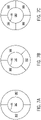
- the extraction system of FIG. 5 also includes a positive pressure head 36, which will described in more detail with regard to FIGS. 6-9 .
- a negative pressure air adjustment 88 may be provided before the suction filter 84.
- This adjustment may comprise, for example, a bypass valve, a louver, or other mechanical device which may be adjusted to limit the flow of air from the suction filter and, consequently, the intake of air into the blower 70 from the ambient surroundings.
- this adjustment may allow some air to exit to the environment, as illustrated in FIG. 5 .
- Such adjustment may advantageously allow for relative mass or volumetric flow rates of the negative pressure airstream to enhance creation of the air region and extraction of workspace air.
- manual adjustment of the negative pressure air stream may be replaced by electronic control via inputs, designated by reference numeral 90. These may be provided on the base unit, such as through adjustment dials, membrane switches, operator touch controls, and so forth. Still further, manual and/or electronic adjustment of one or both airstreams may be provided at the hood 68. In the embodiment illustrated in FIG. 5 , for example, electronic inputs 92 are provided for both adjustments. These are communicated to the remote interface 82 of the base unit which, in turn, communicates them to the control circuitry 74.
- the control circuitry may be coupled to any suitable device, such as the negative pressure adjustment 88 to regulate their operation (e.g., via small adjustment motors and actuator assemblies). It should also be noted that adjustments to flow rates for the negative pressure airstream may be made by altering the speed of one or more motors and/or blowers, fans or compressors.
- a system may be adapted to exchange data with other system components, such as a welding/plasma cutting or other system 94.
- the system 94 may include, for example, welding or plasma cutting power supplies, wire feeders, shielding gas supplies, and so forth.
- the system may include various other manual and machine tools.
- the system may include various robots, production lines, power tools (e.g., saws, workstations, etc.). These will typically be coupled to the operation to accomplish the desired task on a workpiece 18.
- Certain of these systems may be capable of providing control signals to the extraction system to allow for turning the extraction system on and off, regulating speeds and air flows, and so forth.
- Such communications may be provided via suitable cabling 98 or by other means by wireless communications.
- the fan 156 may be a lightweight high speed fan blade configured to rotate in excess of 12,000 rpm.
- the DC motor 154 is disposed downstream of the fan 156 such that the air passing by the DC motor 154 cools the DC motor 154 by convection.
- the DC motor 154 may be located upstream of the fan 156.
- the positive pressure assembly 210 may or may not include a cooling system.
- the rotating fan 156 draws air through an end cap 216, which may be equipped with one or more screens 218 or some other kind of filter in order to prevent debris from being drawn into the positive pressure assembly.
- the end cap 216 supports the one or more screens 218 and provides unrestricted gas stream into the fan 156.
- FIG. 9 merely depicts one embodiment of the positive pressure head 36 and that other embodiments may be possible.
- multiple positive pressure gas stream manifolds 182 may share a single DC motor 154 and/or fan 156.
- the positive pressure system 140, the DC motor 154 and fan 156, or other source of positive pressure gas stream for providing a positive pressure air flow may be located away from the positive pressure head 36, and the positive pressure air flow may be ducted to the positive pressure head.
- each positive pressure assembly may only include a positive pressure gas stream manifold.
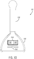
- FIG. 10 shows one embodiment of the handle assembly 214.
- the handle assembly 214 may include a handle 212 and an operator interface 152.
- the handle 212 may be used by the user 16 to position the positive pressure head 36 in the desired location (e.g., near the work surface 14).
- the handle assembly 214 may also include an operator interface 152.
- the operator interface 152 may include a display (e.g., one or more LEDs, a screen, etc.) and/or user inputs (e.g., buttons, knobs, sliders, etc.) or something that acts as both a display and a user input (e.g., a touchscreen).
- a display e.g., one or more LEDs, a screen, etc.
- user inputs e.g., buttons, knobs, sliders, etc.
- the operator interface 152 includes buttons 250, which may include an "on” button and an “off” button, an SPDT switch, or some other combination of buttons (e.g., a button for each motor or fan).
- the operator interface 152 shown in FIG. 10 also includes a slider 252 (e.g. potentiometer), which could be used to control the fan 156 speed of the positive pressure assembly, to operate louvers which act to restrict the gas stream through the positive pressure gas stream manifold, or some other action appropriate for a slider.
- the operator interface 80 may not be mounted on the positive pressure head 36, but on the helmet 22, on the tool 20, or elsewhere within the reach of the user.
- the operator interface 152 may not be mounted on the positive pressure head, but out of reach of the user 16.
- the system may include a remote control on a fob, on the helmet 22, or on the tool 20.
- the extractor system 10 may be started automatically, triggered by an arc sensor to sense with the user 16 begins working.
- the positive pressure system 140 may be shut off based on a timer.
- the helmet 22 may be outfitted with a sensor 24 (e.g., a light sensor or a motion sensor).
- a sensor 24 e.g., a light sensor or a motion sensor.
- a timer may be triggered.
- the positive pressure system 140 may shut off.
- Each positive pressure assembly may be outfitted with a sensor (e.g., proximity sensor) to sense the proximity of a nearby surface (e.g., work surface 14 or wall), at which point the control circuitry 146 may turn off the positive pressure assembly 210 pointed in the direction of the surface.
- a sensor e.g., proximity sensor
- the various positive pressure assemblies of the positive pressure head work in conjunction to create a positive pressure zone and attach to the negative pressure manifold (e.g., conduit 66) of a negative pressure system 60, which creates a negative pressure zone.
- the combination of the positive pressure zone and the negative pressure zone may improve the overall performance of the extraction system 10.
- the creation of a positive pressure zone around the negative pressure zone may enlarge the capture zone from 12-18 inches to approximately 60 inches.
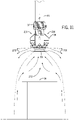
- FIG. 11 shows a positive pressure head 36 mounted to the conduit 66 of a negative pressure system 60, creating a positive pressure zone 270 around a negative pressure zone 272 (as indicated by the different arrow directions).
- FIG. 11 shows a positive pressure head 36 mounted to the conduit 66 of a negative pressure system 60, creating a positive pressure zone 270 around a negative pressure zone 272 (as indicated by the different arrow directions).
- FIG. 11 shows a positive pressure head 36 mounted to the conduit 66 of a negative pressure system 60, creating a positive pressure zone 270 around a
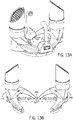
- FIG. 12 shows on embodiment of the extraction system 10 in which the conduit 66 extends horizontally, substantially parallel to the work surface 14, and in which the gas stream through the positive pressure gas stream manifold 182 closest to the work surface 14 is limited.
- the configuration shown in FIG. 12 i.e., one of the positive pressure assemblies 210 facing a nearby surface
- the air would deflect off of the work surface 14 and may inhibit the formation of a positive pressure zone 270 and the negative pressure zone 272.
Landscapes
- Engineering & Computer Science (AREA)
- Mechanical Engineering (AREA)
- Physics & Mathematics (AREA)
- Plasma & Fusion (AREA)
- Chemical & Material Sciences (AREA)
- Combustion & Propulsion (AREA)
- General Engineering & Computer Science (AREA)
- Jet Pumps And Other Pumps (AREA)
- Ventilation (AREA)
Claims (11)
- Système d'extraction (10) comprenant :- une source de flux de gaz à pression négative (70) ;- un conduit à pression négative (66) configuré pour transporter le flux de gaz à pression négative à partir d'une zone de travail (12), dans lequel une première extrémité du conduit à pression négative (66) est couplée à la source de flux de gaz à pression négative (70), de sorte que le flux de gaz à pression négative est transporté à partir de la zone de travail (12) à travers une deuxième extrémité (32) du conduit à pression négative (66) et vers la première extrémité du conduit à pression négative (66) ;- un système à pression positive (140) disposé autour du conduit à pression négative (66) à la deuxième extrémité (32) ; et- une interface opérateur (80, 152) qui permet à un utilisateur de commander un flux de gaz à pression positive,dans lequel le système à pression positive (140) comprend une pluralité d'ensembles à pression positive (210), chaque ensemble à pression positive (210) comprenant un collecteur de flux de gaz à pression positive (182), un moteur (154) disposé à l'intérieur du collecteur de flux de gaz à pression positive (182) ; et un ventilateur (156) couplé au moteur (154), configuré pour générer un flux de gaz à pression positive à travers le collecteur à pression positive (182) ;
caractérisé en ce quel'interface opérateur (80, 152) est configurée pour permettre à un utilisateur de commander la pluralité de moteurs (154),en ce que les ensembles à pression positive (210) sont disposés autour du conduit à pression négative (66) reliés par un ensemble de poignée (214), qui comprend une poignée (212) et l'interface opérateur (152), et en ce que chaque ensemble à pression positive (210) comprend en outre un capuchon d'extrémité (216) et un écran (218), dans lequel le moteur (154) est un moteur à courant continu. - Système d'extraction (10) selon la revendication 1,
dans lequel chacun parmi la pluralité de collecteurs de flux de gaz à pression positive (182) est configuré pour diriger le flux de gaz à pression positive radialement vers l'extérieur. - Système d'extraction (10) selon l'une quelconque des revendications précédentes,
comprenant un ensemble d'évent à lames disposé à l'intérieur de chacun parmi la pluralité de collecteurs de flux de gaz à pression positive (182), dans lequel l'ensemble d'évent à lames limite le flux de gaz à pression positive à travers le collecteur de flux de gaz à pression positive (182) lorsque l'ensemble d'évent à lames est fermé, et dans lequel l'ensemble d'évent à lames permet le flux de gaz à pression positive à travers le collecteur de flux de gaz à pression positive (182) lorsque l'ensemble d'évent à lames est ouvert. - Système d'extraction (10) selon l'une quelconque des revendications précédentes,
dans lequel l'interface opérateur (80, 152) comprend des entrées utilisateur pour l'ouverture et la fermeture de l'ensemble d'évent à lames. - Système d'extraction (10) selon l'une quelconque des revendications précédentes,
dans lequel le système à pression positive (140) est configuré pour être adapté à un conduit à pression négative existant (66). - Système d'extraction (10) selon l'une quelconque
des revendications précédentes, dans lequel chaque ventilateur (156) est disposé en amont du moteur (154) . - Système d'extraction (10) selon l'une quelconque des revendications précédentes,
dans lequel chacun parmi la pluralité d'ensembles à pression positive (210) est couplé l'un à l'autre par des ensembles de charnière (300). - Procédé pour l'extraction de fumées ou de composants en suspension dans des flux d'air au moyen d'un système d'extraction (10) tel que défini dans l'une quelconque des revendications précédentes, comprenant :- la direction d'un flux de gaz à pression négative à travers un conduit à pression négative (66) ;- la direction d'un flux de gaz à pression positive à travers un système à pression positive (140) disposé autour du conduit à pression négative (66) comprenant une pluralité d'ensembles à pression positive (210), chaque ensemble à pression positive comprenant un collecteur de flux de gaz à pression positive (182), un moteur (154) disposé à l'intérieur du collecteur de flux de gaz à pression positive (182) ; et un ventilateur (156) couplé au moteur (154), configuré pour générer un flux de gaz à pression positive à travers le collecteur à pression positive (182) ; et- la limitation du flux de gaz à pression positive à travers un parmi la pluralité de collecteurs de flux de gaz à pression positive (182).
- Procédé selon la revendication 8,
dans lequel le flux de gaz à pression positive est dirigé radialement vers l'extérieur. - Procédé selon la revendication 8 ou 9,
dans lequel le ou les parmi la pluralité de collecteurs de flux de gaz à pression positive (182) à travers lesquels le flux de gaz à pression positive est limité font face à une surface proche, dans lequel la surface proche est une surface de travail (14) ou une paroi. - Procédé selon l'une quelconque des revendications 8 à 10,
dans lequel la limitation du flux de gaz à pression positive à travers le ou les parmi les collecteurs de flux de gaz à pression positive (182) comprend la limitation d'une ou plusieurs sources du flux de gaz à pression positive, ou la limitation substantielle du flux de gaz à pression positive à travers le ou les parmi les collecteurs de flux de gaz à pression positive (182).
Applications Claiming Priority (1)
| Application Number | Priority Date | Filing Date | Title |
|---|---|---|---|
| US14/801,591 US11530826B2 (en) | 2015-07-16 | 2015-07-16 | Extractor with segmented positive pressure airflow system |
Publications (2)
| Publication Number | Publication Date |
|---|---|
| EP3141306A1 EP3141306A1 (fr) | 2017-03-15 |
| EP3141306B1 true EP3141306B1 (fr) | 2022-09-21 |
Family
ID=55970872
Family Applications (1)
| Application Number | Title | Priority Date | Filing Date |
|---|---|---|---|
| EP16169433.6A Active EP3141306B1 (fr) | 2015-07-16 | 2016-05-12 | Extracteur avec système segmenté d'écoulement d'air sous pression positif |
Country Status (5)
| Country | Link |
|---|---|
| US (2) | US11530826B2 (fr) |
| EP (1) | EP3141306B1 (fr) |
| CN (1) | CN106345783B (fr) |
| CA (1) | CA2929363C (fr) |
| MX (1) | MX393672B (fr) |
Families Citing this family (12)
| Publication number | Priority date | Publication date | Assignee | Title |
|---|---|---|---|---|
| US11530826B2 (en) * | 2015-07-16 | 2022-12-20 | Illinois Tool Works Inc. | Extractor with segmented positive pressure airflow system |
| CA2976081C (fr) * | 2016-08-10 | 2025-01-14 | Pat Technology Systems Inc. | Appareil d'extraction d'emanations a ouverture d'extraction deplacable |
| US20180339358A1 (en) * | 2017-05-26 | 2018-11-29 | Robovent Products Group, Inc. | Fume extraction assembly for gas shielded welding |
| US11318509B2 (en) * | 2017-11-06 | 2022-05-03 | Air Systems Design, Inc. | Dust hood |
| US11479373B2 (en) * | 2018-08-14 | 2022-10-25 | Honeybee Robotics, Llc | Sample collection system for interplanetary vehicle |
| RU2700230C1 (ru) * | 2019-01-15 | 2019-09-13 | Акционерное общество "Научно-производственное объединение "СПЛАВ" | Способ изготовления осесимметричного сварного корпуса сосуда высокого давления |
| US11938571B2 (en) * | 2019-11-18 | 2024-03-26 | Illinois Tool Works Inc. | Methods and apparatuses for a ventilation nozzle for welding applications |
| WO2021113437A1 (fr) | 2019-12-05 | 2021-06-10 | Donaldson Company, Inc. | Extracteur de fumées |
| CN111396335B (zh) * | 2020-03-25 | 2022-01-21 | 上海能源建设集团有限公司 | 针对隧道内管道焊接的气体排污系统 |
| US20220097108A1 (en) * | 2020-09-28 | 2022-03-31 | Lincoln Global, Inc. | Methods and systems for controlling welding fume extraction |
| CN112317931A (zh) * | 2020-11-11 | 2021-02-05 | 江苏鑫州耐磨科技有限公司 | 一种配套于平板堆焊机的除烟装置 |
| CN114473304B (zh) * | 2022-02-28 | 2024-08-02 | 台州竞添机电有限公司 | 一种电焊机电子元件降温装置 |
Citations (2)
| Publication number | Priority date | Publication date | Assignee | Title |
|---|---|---|---|---|
| WO2008148712A2 (fr) * | 2007-06-06 | 2008-12-11 | Veljko Martic | Hotte d'extraction pour cuisine avec agencement innovant |
| US20130244558A1 (en) * | 2012-03-16 | 2013-09-19 | Illinois Tool Works Inc. | Airborne component extractor with adjustable flow rates |
Family Cites Families (137)
| Publication number | Priority date | Publication date | Assignee | Title |
|---|---|---|---|---|
| USRE24637E (en) | 1959-04-21 | Foraminous ceiling ventilating apparatus | ||
| US2210458A (en) | 1936-11-16 | 1940-08-06 | Lester S Keilholtz | Method of and apparatus for air conditioning |
| US2289474A (en) | 1937-05-18 | 1942-07-14 | American Blower Corp | Apparatus for dust collection |
| US2185919A (en) | 1938-01-15 | 1940-01-02 | Franz J Kurth | Ventilating device |
| GB546878A (en) | 1941-12-11 | 1942-08-04 | Thomas Ash & Company Ltd | Improvements in or relating to dust-extracting or filtering apparatus |
| US2367104A (en) | 1943-02-06 | 1945-01-09 | Demuth Charles | Variable volume air distributor |
| US2370748A (en) * | 1943-04-12 | 1945-03-06 | Econo Safety Devices Inc | Hinged clamp |
| US2910558A (en) | 1957-09-30 | 1959-10-27 | Martin Co | Electrical phase sequence switch |
| US3364664A (en) | 1964-07-20 | 1968-01-23 | Cockle Ventilator Company Inc | Grease extractor for ventilating systems |
| NL123386C (fr) | 1965-01-14 | 1967-07-17 | ||
| US3318227A (en) | 1965-03-10 | 1967-05-09 | Kewaunee Mfg Company | Fume hood |
| FR1513243A (fr) | 1966-05-09 | 1968-02-16 | Micro-capteur mobile pour fumées et vapeurs | |
| DE1604293C3 (de) | 1966-12-21 | 1973-10-18 | Siemens Electrogeraete Gmbh, 1000 Berlin Und 8000 Muenchen | Dunstabzugshaube |
| NO119851B (fr) * | 1967-01-30 | 1970-07-13 | Nordisk Ventilator | |
| US3484890A (en) | 1968-03-12 | 1969-12-23 | William H Case | Pressure-vacuum cleaning and treating device |
| BE792270A (fr) | 1971-12-07 | 1973-03-30 | Cometal | Ensemble de hotte aspirante pour capter et evacuer des gaz ou autres |
| FR2208317A6 (fr) | 1972-11-23 | 1974-06-21 | Cometal | |
| US4016398A (en) | 1974-11-02 | 1977-04-05 | Caterpillar Tractor Co. | Fume extraction control for welding gun |
| DK630174A (da) | 1974-12-04 | 1976-06-05 | C P N Aaberg | Apparat til punktafsugning ved svejsning og andre luftforurenende processer |
| SE424409B (sv) | 1975-12-04 | 1982-07-19 | Coral Sas | Anordning for lokaliserad utsugning av gaser, rokstoft och liknande |
| US4160407A (en) | 1977-11-18 | 1979-07-10 | Bell Telephone Laboratories, Incorporated | Ventilating system |
| JPS54147647A (en) | 1978-05-12 | 1979-11-19 | Hitachi Plant Eng & Constr Co Ltd | Exhaust hood |
| US4163650A (en) | 1978-07-24 | 1979-08-07 | Tepco, Incorporated | Portable electronic precipitator |
| DE2837543C2 (de) | 1978-08-28 | 1984-03-15 | Miguel 8131 Berg Kling | Dunstabzugsvorrichtung |
| GB2030825B (en) | 1978-09-27 | 1982-11-17 | Plessey Co Ltd | Message broadcast system receiver arrangement |
| GB2032825A (en) | 1978-10-21 | 1980-05-14 | Ho Wai Chau | Welding apparatus with automatically operated fume extractor |
| US4905716A (en) | 1979-08-24 | 1990-03-06 | Tom Hubbard | Hood for permanent wave rod or curler |
| US4358300A (en) | 1981-06-05 | 1982-11-09 | J. I. Case Company | Welding fume and spark trap |
| US4493970A (en) | 1983-01-17 | 1985-01-15 | Arcair Company | Slag and fume collector for air carbon-arc cutting and gouging torches |
| JPS6034713A (ja) | 1983-08-04 | 1985-02-22 | Kurako:Kk | オイルエリミネ−タ−及び油脂分離回収装置 |
| US4502375A (en) | 1983-08-18 | 1985-03-05 | Tri City Laboratory Specialists, Inc. | Fume hood sash operator |
| DE3412204A1 (de) | 1984-04-02 | 1985-10-10 | Bals Elektrotechnik Gmbh & Co Kg, 5942 Kirchhundem | Netzanschlussgeraet |
| US4552059A (en) | 1984-09-18 | 1985-11-12 | Cambridge Engineering, Inc. | Flow measurement for exhaust-type canopy and ventilating hood |
| JPS62137182A (ja) | 1985-12-10 | 1987-06-20 | Miyachi Denshi Kk | 抵抗溶接制御装置 |
| FR2613551B1 (fr) | 1987-04-01 | 1992-12-24 | Lebihan Lemouel Sa Ets | Dispositif automatique de correction de l'ordre de succession des phases de l'alimentation triphasee d'une installation electrique |
| DE3716257A1 (de) | 1987-05-15 | 1988-11-24 | Takeo Imai | Verfahren und vorrichtung zum auffangen verschmutzter substanzen |
| JPH0833227B2 (ja) | 1988-01-05 | 1996-03-29 | 三菱重工業株式会社 | 流体処理装置 |
| CN2043140U (zh) | 1989-01-28 | 1989-08-23 | 辽宁省节能环保设备厂 | 一种集气排气的气幕机 |
| US4969923A (en) | 1989-06-01 | 1990-11-13 | Aeroquip Corporation | Safety latch |
| DE3928621C2 (de) | 1989-08-30 | 1995-03-30 | Krantz Tkt Gmbh | Bodenquellauslaß |
| CH682512A5 (de) | 1990-03-02 | 1993-09-30 | Zurecon Ag | Dampfabzugeinrichtung. |
| JP2836925B2 (ja) | 1990-06-29 | 1998-12-14 | 三菱重工業株式会社 | 流体吸引ノズル及び流体処理装置 |
| US5069197A (en) | 1990-09-26 | 1991-12-03 | Wisting Walter L | Fume hood |
| JPH04327736A (ja) | 1991-04-30 | 1992-11-17 | Mitsubishi Heavy Ind Ltd | 流体吸引ノズル及び流体処理装置 |
| JPH0659742U (ja) | 1991-10-09 | 1994-08-19 | 日本メタル工業株式会社 | 集塵装置 |
| CN2121638U (zh) | 1992-01-25 | 1992-11-11 | 江照政 | 一种防止油烟外散的排油烟机 |
| CN2146665Y (zh) | 1992-03-17 | 1993-11-17 | 吕瑞莲 | 家用电气化多功能高效煤灶 |
| SE506838C2 (sv) | 1992-04-21 | 1998-02-16 | Plymex Fabriksfoersaeljning Ab | Inställbar punktutsugningsanordning med filter |
| CN2129656Y (zh) | 1992-08-10 | 1993-04-14 | 北京供电局 | 除尘机 |
| US5223005A (en) | 1992-08-14 | 1993-06-29 | Aercology, Inc. | Dust and fume collector |
| US5281246A (en) | 1992-12-23 | 1994-01-25 | Metal-Fab, Inc. | Air cleaner assembly |
| US5336130A (en) * | 1993-03-04 | 1994-08-09 | Metal-Fab, Inc. | Adjustable exhauster arm assembly |
| JP3111125B2 (ja) | 1993-04-12 | 2000-11-20 | 日鐵溶接工業株式会社 | 溶接ヒューム湿式捕集処理方法及びその装置 |
| US5410120A (en) | 1993-06-29 | 1995-04-25 | Apex Engineering Company | Welding enclosure assembly |
| US5713346A (en) | 1993-08-11 | 1998-02-03 | D.E.R. Investments Ltd. | Apparatus and method for removing fumes from the space above a cooking appliance |
| US5395410A (en) | 1993-12-21 | 1995-03-07 | Jang; Sun-Sing | Fume exhauster |
| DE4413600A1 (de) | 1994-04-20 | 1995-11-16 | Wolfgang Von Laufenberg | Entsorgung von Luftschadstoffen |
| JP3303532B2 (ja) | 1994-07-13 | 2002-07-22 | 国産電機株式会社 | 内燃機関用電源装置 |
| JP2609208B2 (ja) | 1995-03-08 | 1997-05-14 | 善洋 山田 | 調理場用の排気装置 |
| CN2225253Y (zh) | 1995-03-18 | 1996-04-24 | 重庆医科大学临床学院 | 输液配药仪 |
| US5540214A (en) | 1995-05-18 | 1996-07-30 | Boudreault; Jean-Pierre | Exhaust hood |
| US5718219A (en) | 1997-01-10 | 1998-02-17 | Boudreault; Jean-Pierre | Kitchen exhaust hood assembly |
| US6607573B1 (en) | 1997-02-06 | 2003-08-19 | Northrop Grumman Corporation | Portable air pollution control apparatus |
| US5716268A (en) | 1997-02-18 | 1998-02-10 | Plymovent Ab | Device for removal of deleterious impurities from room atmosphere |
| IT1291164B1 (it) | 1997-03-04 | 1998-12-29 | Coral Spa | Condotto universale di convogliamento di fumi o gas nocivi da un posto di lavorazione. |
| NO971697L (no) | 1997-04-14 | 1998-10-15 | Vidar Wiik | Anordning til fjerning av gass og partikler i forbindelse med sveising/skjµrebrenning |
| JPH10288371A (ja) | 1997-04-16 | 1998-10-27 | Shinpo Kk | 排気装置 |
| US6037725A (en) | 1998-01-28 | 2000-03-14 | Bristol Compressors, Inc. | Two step power output motor |
| US6099607A (en) | 1998-07-22 | 2000-08-08 | Haslebacher; William J. | Rollably positioned, adjustably directable clean air delivery supply assembly, for use in weather protected environments to provide localized clean air, where activities require clean air quality per strict specifications |
| FI990302A7 (fi) | 1999-02-15 | 2000-08-16 | Juha Tapio Koskinen | Menetelmä ja sovitelma hitsaamotilojen ilmanvaihdon säätöä varten |
| JP2001174037A (ja) | 1999-07-01 | 2001-06-29 | Daikin Ind Ltd | トルネード型吸気・送風装置 |
| JP3395736B2 (ja) | 1999-10-26 | 2003-04-14 | ダイキン工業株式会社 | 給排気装置 |
| CN2413708Y (zh) | 2000-03-31 | 2001-01-10 | 吴金岭 | 一次性胸腹腔治疗器 |
| US6358137B1 (en) | 2000-04-17 | 2002-03-19 | Siemens Building Technologies, Inc. | Laboratory fume hood control apparatus having rotary sash door position sensor |
| DE10020736A1 (de) | 2000-04-27 | 2001-10-31 | Bsh Bosch Siemens Hausgeraete | Dunstabzugshaube |
| US7000634B2 (en) | 2000-10-26 | 2006-02-21 | Lindinvent Ab | Adjustable valve for variable flows and a method for reducing flow through a valve |
| US6616720B1 (en) | 2001-02-16 | 2003-09-09 | William C. Smith | Portable airborne contamination control system including a main and remote unit |
| US20030181158A1 (en) | 2002-01-31 | 2003-09-25 | Edwards Systems Technology, Inc. | Economizer control |
| KR100463484B1 (ko) | 2002-02-08 | 2004-12-29 | 조 원 장 | 개인 대응형 공기청정장치 |
| CN2593015Y (zh) | 2002-04-05 | 2003-12-17 | 张亚丹 | 多弹簧外装可调式球面密封旋转接头 |
| DE20221100U1 (de) | 2002-04-11 | 2005-01-27 | Maier, Max | Dunstabsaugvorrichtung für ein Kochfeld o.dgl. und insbesondere dafür geeigneter Fettfilter |
| WO2004088812A1 (fr) | 2003-04-04 | 2004-10-14 | Theodore Strauss | Dispositif de protection pour equipement electrique triphase |
| WO2005022046A1 (fr) | 2003-08-27 | 2005-03-10 | Axima Ag | Systeme servant a aspirer en particulier de l'air charge de substances polluantes |
| FI20035203A0 (fi) | 2003-11-11 | 2003-11-11 | Antero Heinonen | Järjestely keittiölaitteen ilmanpoistossa |
| CA2493651C (fr) | 2004-01-20 | 2014-05-20 | Greenheck Fan Corporation | Ventilateur-extracteur equipe d'une bande de mixage d'air |
| US7682231B2 (en) | 2004-01-20 | 2010-03-23 | Greenheck Fan Corporation | Exhaust fan assembly |
| JP2005279200A (ja) | 2004-03-29 | 2005-10-13 | Showarasenkan Seisakusho Co Ltd | スプリンクラー巻き出し管の接続構造、及び、スプリンクラー巻き出し管 |
| GR1004782B (el) | 2004-04-30 | 2005-01-25 | Αντωνιος Αρχοντουλης | Συστημα αποφυγης δημιουργιας υποπιεσης στο χωρο του σπιτιου απο οικιακους απορροφητηρες κουζινας |
| US20060157048A1 (en) | 2004-12-17 | 2006-07-20 | Heilman Nikolaus J | Grease extraction system, particulate extractor, and method |
| US7783383B2 (en) | 2004-12-22 | 2010-08-24 | Intelligent Hospital Systems Ltd. | Automated pharmacy admixture system (APAS) |
| DE102005016721A1 (de) | 2005-04-11 | 2006-10-12 | Siemens Ag | Netz-Überwachungsrelais mit Schaltausgang zur automatischen Phasenkorrektur |
| DE102005033224A1 (de) | 2005-07-15 | 2007-01-18 | BSH Bosch und Siemens Hausgeräte GmbH | Dunstabzugshaube und Dunstabzugsvorrichtung |
| US8312873B2 (en) | 2005-08-01 | 2012-11-20 | Western Industries, Inc. | Low depth telescoping downdraft ventilator |
| CN100528335C (zh) | 2005-08-17 | 2009-08-19 | 张才腾 | 产生漩涡液态流或漩涡燃烧流的挡板组合结构 |
| TWI291002B (en) | 2006-02-24 | 2007-12-11 | Acxing Ind Co Ltd | The structure and the method of the auxiliary gas exhaust |
| CN2897469Y (zh) | 2006-05-11 | 2007-05-09 | 润鸣新素材(通辽)有限公司 | 碳化硼冶炼烟气处理器 |
| JP2008070049A (ja) | 2006-09-14 | 2008-03-27 | Toto Ltd | レンジフード |
| CN200984583Y (zh) | 2006-11-06 | 2007-12-05 | 张应贤 | 电焊烟尘气体处理净化机 |
| DE102006055001A1 (de) | 2006-11-17 | 2008-05-21 | Bohner Produktions Gmbh | Dunstabsaugeinrichtung |
| US7559962B2 (en) | 2006-12-22 | 2009-07-14 | Miller Richard L | Apparatus for on-site cleaning of landscape rock |
| FR2911520B1 (fr) | 2007-01-19 | 2009-08-28 | Roblin Sas Soc Par Actions Sim | Hotte aspirante pour cuisine |
| EP1967796A1 (fr) | 2007-03-08 | 2008-09-10 | Itho B.V. | Hotte de cuisson avec rideau d'air |
| US20080278040A1 (en) | 2007-05-10 | 2008-11-13 | Mccarthy Larry A | Air bypass system for biosafety cabinets |
| US20080305731A1 (en) | 2007-06-08 | 2008-12-11 | Reid James K | Positionable back draft assembly |
| CN101327109B (zh) | 2007-06-18 | 2011-12-07 | 苏州宝时得电动工具有限公司 | 吹吸机 |
| US8083574B2 (en) | 2007-09-27 | 2011-12-27 | John G. Arnold, Jr. | Exhaust flue cap and filter device for a gas fired appliance |
| US7581539B2 (en) | 2008-01-31 | 2009-09-01 | Franklin Machine Products | Baffle-type grease filters for kitchen ventilators |
| US8176766B1 (en) | 2008-03-27 | 2012-05-15 | Alcotek, Inc. | Liquid and solid trapping mouthpiece |
| US9180547B2 (en) | 2008-06-30 | 2015-11-10 | Caterpillar Inc. | Robotic welder having fume extraction |
| CN101332392B (zh) | 2008-08-01 | 2010-10-20 | 上海台安工程实业有限公司 | 改性沥青生产车间综合环保处理装置 |
| JP5155091B2 (ja) | 2008-10-10 | 2013-02-27 | 株式会社Trinc | 除塵機 |
| US8460417B2 (en) | 2008-11-11 | 2013-06-11 | Great Lakes Air Systems, Inc. | Portable air filtration system |
| US20100206799A1 (en) | 2009-02-17 | 2010-08-19 | Fluid Treatments Systems, Inc. | Liquid Filter |
| CN101526239B (zh) | 2009-04-14 | 2012-07-11 | 杭州六易科技有限公司 | 集烟罩可升降的油烟机 |
| US20100282728A1 (en) | 2009-05-11 | 2010-11-11 | Lincoln Global, Inc. | Power source with fume extractor for welding |
| DE102009030220A1 (de) | 2009-06-23 | 2010-12-30 | Udo Berling | Dunstabzugshaube |
| WO2011006245A1 (fr) | 2009-07-17 | 2011-01-20 | Diversitech Equipment And Sales (1984) Ltd. | Système dextraction de fumée à positionnement automatique de hotte |
| CN201578942U (zh) | 2010-01-05 | 2010-09-15 | 上海辰礼投资发展有限公司 | 重力失速式集尘器 |
| CN201609707U (zh) | 2010-01-14 | 2010-10-20 | 宝山钢铁股份有限公司 | 物料除尘系统 |
| CN201644480U (zh) | 2010-03-17 | 2010-11-24 | 中船第九设计研究院工程有限公司 | 一种多工位焊接烟尘的净化系统 |
| JP5162612B2 (ja) | 2010-03-26 | 2013-03-13 | 三星ダイヤモンド工業株式会社 | エア集塵装置 |
| DE202010009611U1 (de) | 2010-06-28 | 2010-10-28 | Esta Apparatebau Gmbh & Co. Kg | Schweißrauchabsauganlage |
| US9228767B2 (en) | 2010-09-15 | 2016-01-05 | Carrier Corporation | Method for determining proper wiring of multiple 3 phase motors in a single system |
| US9623506B2 (en) | 2011-02-01 | 2017-04-18 | Illinois Tool Works Inc. | Fume extractor for welding applications |
| CN202087569U (zh) | 2011-05-09 | 2011-12-28 | 河南中烟工业有限责任公司 | 负压吸尘罩 |
| US9821351B2 (en) | 2011-11-11 | 2017-11-21 | Illinois Tool Works Inc. | Welding fume extractor |
| KR101335662B1 (ko) | 2012-04-03 | 2013-12-03 | 주식회사트라이애드 | 회전체 내장형 후드 시스템 |
| CN102699002B (zh) | 2012-05-11 | 2015-04-29 | 奇瑞汽车股份有限公司 | 一种单工位焊装排尘设备 |
| CN203008443U (zh) | 2012-12-21 | 2013-06-19 | 广西力源宝农林科技发展有限责任公司 | 一种除臭环保厂房 |
| US20140214213A1 (en) | 2013-01-29 | 2014-07-31 | Rocky Research | Utility control of hvac with integral electrical storage unit |
| US9839948B2 (en) | 2013-01-29 | 2017-12-12 | Illinois Tool Works Inc. | Fume evacuation system |
| GB2511564B (en) | 2013-03-08 | 2020-05-27 | Nidec Control Techniques Ltd | Fail Safe Circuit |
| US10808953B2 (en) | 2013-06-28 | 2020-10-20 | Illinois Tool Works Inc. | Airborne component extractor with baffled debris collection |
| US9272237B2 (en) | 2013-06-28 | 2016-03-01 | Illinois Tool Works Inc. | Three-phase portable airborne component extractor with rotational direction control |
| US20160131391A1 (en) * | 2014-11-03 | 2016-05-12 | The Regents Of The University Of California | Electroactive smart hvac vent register |
| US11530826B2 (en) | 2015-07-16 | 2022-12-20 | Illinois Tool Works Inc. | Extractor with segmented positive pressure airflow system |
| US11014132B2 (en) | 2015-07-16 | 2021-05-25 | Illinois Tool Works Inc. | Extractor with end-mounted positive pressure system |
-
2015
- 2015-07-16 US US14/801,591 patent/US11530826B2/en active Active
-
2016
- 2016-05-09 CA CA2929363A patent/CA2929363C/fr active Active
- 2016-05-12 EP EP16169433.6A patent/EP3141306B1/fr active Active
- 2016-07-04 CN CN201610518055.0A patent/CN106345783B/zh not_active Expired - Fee Related
- 2016-07-14 MX MX2016009237A patent/MX393672B/es unknown
-
2022
- 2022-12-14 US US18/081,001 patent/US12398895B2/en active Active
Patent Citations (2)
| Publication number | Priority date | Publication date | Assignee | Title |
|---|---|---|---|---|
| WO2008148712A2 (fr) * | 2007-06-06 | 2008-12-11 | Veljko Martic | Hotte d'extraction pour cuisine avec agencement innovant |
| US20130244558A1 (en) * | 2012-03-16 | 2013-09-19 | Illinois Tool Works Inc. | Airborne component extractor with adjustable flow rates |
Also Published As
| Publication number | Publication date |
|---|---|
| MX2016009237A (es) | 2017-04-27 |
| CA2929363C (fr) | 2020-08-18 |
| US20170016640A1 (en) | 2017-01-19 |
| MX393672B (es) | 2025-03-24 |
| CN106345783A (zh) | 2017-01-25 |
| CA2929363A1 (fr) | 2017-01-16 |
| US11530826B2 (en) | 2022-12-20 |
| US12398895B2 (en) | 2025-08-26 |
| CN106345783B (zh) | 2021-06-04 |
| EP3141306A1 (fr) | 2017-03-15 |
| US20230111903A1 (en) | 2023-04-13 |
Similar Documents
| Publication | Publication Date | Title |
|---|---|---|
| US12398895B2 (en) | Extractor with segmented positive pressure airflow system | |
| EP3117911B1 (fr) | Extracteur avec système de pression positive monté à une extrémité | |
| CA2866967C (fr) | Extracteur de composant en suspension dans l'air avec debits reglables | |
| EP4487985A1 (fr) | Systèmes de collecte de fumées de soudage |
Legal Events
| Date | Code | Title | Description |
|---|---|---|---|
| PUAI | Public reference made under article 153(3) epc to a published international application that has entered the european phase |
Free format text: ORIGINAL CODE: 0009012 |
|
| STAA | Information on the status of an ep patent application or granted ep patent |
Free format text: STATUS: REQUEST FOR EXAMINATION WAS MADE |
|
| 17P | Request for examination filed |
Effective date: 20160512 |
|
| AK | Designated contracting states |
Kind code of ref document: A1 Designated state(s): AL AT BE BG CH CY CZ DE DK EE ES FI FR GB GR HR HU IE IS IT LI LT LU LV MC MK MT NL NO PL PT RO RS SE SI SK SM TR |
|
| AX | Request for extension of the european patent |
Extension state: BA ME |
|
| STAA | Information on the status of an ep patent application or granted ep patent |
Free format text: STATUS: EXAMINATION IS IN PROGRESS |
|
| 17Q | First examination report despatched |
Effective date: 20200318 |
|
| GRAP | Despatch of communication of intention to grant a patent |
Free format text: ORIGINAL CODE: EPIDOSNIGR1 |
|
| STAA | Information on the status of an ep patent application or granted ep patent |
Free format text: STATUS: GRANT OF PATENT IS INTENDED |
|
| INTG | Intention to grant announced |
Effective date: 20220413 |
|
| GRAS | Grant fee paid |
Free format text: ORIGINAL CODE: EPIDOSNIGR3 |
|
| GRAA | (expected) grant |
Free format text: ORIGINAL CODE: 0009210 |
|
| STAA | Information on the status of an ep patent application or granted ep patent |
Free format text: STATUS: THE PATENT HAS BEEN GRANTED |
|
| AK | Designated contracting states |
Kind code of ref document: B1 Designated state(s): AL AT BE BG CH CY CZ DE DK EE ES FI FR GB GR HR HU IE IS IT LI LT LU LV MC MK MT NL NO PL PT RO RS SE SI SK SM TR |
|
| REG | Reference to a national code |
Ref country code: GB Ref legal event code: FG4D |
|
| REG | Reference to a national code |
Ref country code: CH Ref legal event code: EP |
|
| REG | Reference to a national code |
Ref country code: IE Ref legal event code: FG4D |
|
| REG | Reference to a national code |
Ref country code: DE Ref legal event code: R096 Ref document number: 602016075113 Country of ref document: DE |
|
| REG | Reference to a national code |
Ref country code: AT Ref legal event code: REF Ref document number: 1519710 Country of ref document: AT Kind code of ref document: T Effective date: 20221015 |
|
| REG | Reference to a national code |
Ref country code: LT Ref legal event code: MG9D |
|
| REG | Reference to a national code |
Ref country code: NL Ref legal event code: MP Effective date: 20220921 |
|
| PG25 | Lapsed in a contracting state [announced via postgrant information from national office to epo] |
Ref country code: SE Free format text: LAPSE BECAUSE OF FAILURE TO SUBMIT A TRANSLATION OF THE DESCRIPTION OR TO PAY THE FEE WITHIN THE PRESCRIBED TIME-LIMIT Effective date: 20220921 Ref country code: RS Free format text: LAPSE BECAUSE OF FAILURE TO SUBMIT A TRANSLATION OF THE DESCRIPTION OR TO PAY THE FEE WITHIN THE PRESCRIBED TIME-LIMIT Effective date: 20220921 Ref country code: NO Free format text: LAPSE BECAUSE OF FAILURE TO SUBMIT A TRANSLATION OF THE DESCRIPTION OR TO PAY THE FEE WITHIN THE PRESCRIBED TIME-LIMIT Effective date: 20221221 Ref country code: LV Free format text: LAPSE BECAUSE OF FAILURE TO SUBMIT A TRANSLATION OF THE DESCRIPTION OR TO PAY THE FEE WITHIN THE PRESCRIBED TIME-LIMIT Effective date: 20220921 Ref country code: LT Free format text: LAPSE BECAUSE OF FAILURE TO SUBMIT A TRANSLATION OF THE DESCRIPTION OR TO PAY THE FEE WITHIN THE PRESCRIBED TIME-LIMIT Effective date: 20220921 Ref country code: FI Free format text: LAPSE BECAUSE OF FAILURE TO SUBMIT A TRANSLATION OF THE DESCRIPTION OR TO PAY THE FEE WITHIN THE PRESCRIBED TIME-LIMIT Effective date: 20220921 |
|
| REG | Reference to a national code |
Ref country code: AT Ref legal event code: MK05 Ref document number: 1519710 Country of ref document: AT Kind code of ref document: T Effective date: 20220921 |
|
| PG25 | Lapsed in a contracting state [announced via postgrant information from national office to epo] |
Ref country code: HR Free format text: LAPSE BECAUSE OF FAILURE TO SUBMIT A TRANSLATION OF THE DESCRIPTION OR TO PAY THE FEE WITHIN THE PRESCRIBED TIME-LIMIT Effective date: 20220921 Ref country code: GR Free format text: LAPSE BECAUSE OF FAILURE TO SUBMIT A TRANSLATION OF THE DESCRIPTION OR TO PAY THE FEE WITHIN THE PRESCRIBED TIME-LIMIT Effective date: 20221222 |
|
| PG25 | Lapsed in a contracting state [announced via postgrant information from national office to epo] |
Ref country code: SM Free format text: LAPSE BECAUSE OF FAILURE TO SUBMIT A TRANSLATION OF THE DESCRIPTION OR TO PAY THE FEE WITHIN THE PRESCRIBED TIME-LIMIT Effective date: 20220921 Ref country code: RO Free format text: LAPSE BECAUSE OF FAILURE TO SUBMIT A TRANSLATION OF THE DESCRIPTION OR TO PAY THE FEE WITHIN THE PRESCRIBED TIME-LIMIT Effective date: 20220921 Ref country code: PT Free format text: LAPSE BECAUSE OF FAILURE TO SUBMIT A TRANSLATION OF THE DESCRIPTION OR TO PAY THE FEE WITHIN THE PRESCRIBED TIME-LIMIT Effective date: 20230123 Ref country code: ES Free format text: LAPSE BECAUSE OF FAILURE TO SUBMIT A TRANSLATION OF THE DESCRIPTION OR TO PAY THE FEE WITHIN THE PRESCRIBED TIME-LIMIT Effective date: 20220921 Ref country code: CZ Free format text: LAPSE BECAUSE OF FAILURE TO SUBMIT A TRANSLATION OF THE DESCRIPTION OR TO PAY THE FEE WITHIN THE PRESCRIBED TIME-LIMIT Effective date: 20220921 Ref country code: AT Free format text: LAPSE BECAUSE OF FAILURE TO SUBMIT A TRANSLATION OF THE DESCRIPTION OR TO PAY THE FEE WITHIN THE PRESCRIBED TIME-LIMIT Effective date: 20220921 |
|
| PG25 | Lapsed in a contracting state [announced via postgrant information from national office to epo] |
Ref country code: SK Free format text: LAPSE BECAUSE OF FAILURE TO SUBMIT A TRANSLATION OF THE DESCRIPTION OR TO PAY THE FEE WITHIN THE PRESCRIBED TIME-LIMIT Effective date: 20220921 Ref country code: PL Free format text: LAPSE BECAUSE OF FAILURE TO SUBMIT A TRANSLATION OF THE DESCRIPTION OR TO PAY THE FEE WITHIN THE PRESCRIBED TIME-LIMIT Effective date: 20220921 Ref country code: IS Free format text: LAPSE BECAUSE OF FAILURE TO SUBMIT A TRANSLATION OF THE DESCRIPTION OR TO PAY THE FEE WITHIN THE PRESCRIBED TIME-LIMIT Effective date: 20230121 Ref country code: EE Free format text: LAPSE BECAUSE OF FAILURE TO SUBMIT A TRANSLATION OF THE DESCRIPTION OR TO PAY THE FEE WITHIN THE PRESCRIBED TIME-LIMIT Effective date: 20220921 |
|
| REG | Reference to a national code |
Ref country code: DE Ref legal event code: R097 Ref document number: 602016075113 Country of ref document: DE |
|
| PG25 | Lapsed in a contracting state [announced via postgrant information from national office to epo] |
Ref country code: NL Free format text: LAPSE BECAUSE OF FAILURE TO SUBMIT A TRANSLATION OF THE DESCRIPTION OR TO PAY THE FEE WITHIN THE PRESCRIBED TIME-LIMIT Effective date: 20220921 Ref country code: AL Free format text: LAPSE BECAUSE OF FAILURE TO SUBMIT A TRANSLATION OF THE DESCRIPTION OR TO PAY THE FEE WITHIN THE PRESCRIBED TIME-LIMIT Effective date: 20220921 |
|
| P01 | Opt-out of the competence of the unified patent court (upc) registered |
Effective date: 20230606 |
|
| PLBE | No opposition filed within time limit |
Free format text: ORIGINAL CODE: 0009261 |
|
| STAA | Information on the status of an ep patent application or granted ep patent |
Free format text: STATUS: NO OPPOSITION FILED WITHIN TIME LIMIT |
|
| PG25 | Lapsed in a contracting state [announced via postgrant information from national office to epo] |
Ref country code: DK Free format text: LAPSE BECAUSE OF FAILURE TO SUBMIT A TRANSLATION OF THE DESCRIPTION OR TO PAY THE FEE WITHIN THE PRESCRIBED TIME-LIMIT Effective date: 20220921 |
|
| 26N | No opposition filed |
Effective date: 20230622 |
|
| PG25 | Lapsed in a contracting state [announced via postgrant information from national office to epo] |
Ref country code: SI Free format text: LAPSE BECAUSE OF FAILURE TO SUBMIT A TRANSLATION OF THE DESCRIPTION OR TO PAY THE FEE WITHIN THE PRESCRIBED TIME-LIMIT Effective date: 20220921 |
|
| REG | Reference to a national code |
Ref country code: CH Ref legal event code: PL |
|
| PG25 | Lapsed in a contracting state [announced via postgrant information from national office to epo] |
Ref country code: MC Free format text: LAPSE BECAUSE OF FAILURE TO SUBMIT A TRANSLATION OF THE DESCRIPTION OR TO PAY THE FEE WITHIN THE PRESCRIBED TIME-LIMIT Effective date: 20220921 |
|
| GBPC | Gb: european patent ceased through non-payment of renewal fee |
Effective date: 20230512 |
|
| REG | Reference to a national code |
Ref country code: BE Ref legal event code: MM Effective date: 20230531 |
|
| PG25 | Lapsed in a contracting state [announced via postgrant information from national office to epo] |
Ref country code: MC Free format text: LAPSE BECAUSE OF FAILURE TO SUBMIT A TRANSLATION OF THE DESCRIPTION OR TO PAY THE FEE WITHIN THE PRESCRIBED TIME-LIMIT Effective date: 20220921 Ref country code: LU Free format text: LAPSE BECAUSE OF NON-PAYMENT OF DUE FEES Effective date: 20230512 Ref country code: LI Free format text: LAPSE BECAUSE OF NON-PAYMENT OF DUE FEES Effective date: 20230531 Ref country code: CH Free format text: LAPSE BECAUSE OF NON-PAYMENT OF DUE FEES Effective date: 20230531 |
|
| REG | Reference to a national code |
Ref country code: IE Ref legal event code: MM4A |
|
| PG25 | Lapsed in a contracting state [announced via postgrant information from national office to epo] |
Ref country code: IE Free format text: LAPSE BECAUSE OF NON-PAYMENT OF DUE FEES Effective date: 20230512 |
|
| PG25 | Lapsed in a contracting state [announced via postgrant information from national office to epo] |
Ref country code: IE Free format text: LAPSE BECAUSE OF NON-PAYMENT OF DUE FEES Effective date: 20230512 Ref country code: GB Free format text: LAPSE BECAUSE OF NON-PAYMENT OF DUE FEES Effective date: 20230512 |
|
| PG25 | Lapsed in a contracting state [announced via postgrant information from national office to epo] |
Ref country code: FR Free format text: LAPSE BECAUSE OF NON-PAYMENT OF DUE FEES Effective date: 20230531 Ref country code: BE Free format text: LAPSE BECAUSE OF NON-PAYMENT OF DUE FEES Effective date: 20230531 |
|
| PG25 | Lapsed in a contracting state [announced via postgrant information from national office to epo] |
Ref country code: BG Free format text: LAPSE BECAUSE OF FAILURE TO SUBMIT A TRANSLATION OF THE DESCRIPTION OR TO PAY THE FEE WITHIN THE PRESCRIBED TIME-LIMIT Effective date: 20220921 |
|
| PG25 | Lapsed in a contracting state [announced via postgrant information from national office to epo] |
Ref country code: BG Free format text: LAPSE BECAUSE OF FAILURE TO SUBMIT A TRANSLATION OF THE DESCRIPTION OR TO PAY THE FEE WITHIN THE PRESCRIBED TIME-LIMIT Effective date: 20220921 |
|
| PGFP | Annual fee paid to national office [announced via postgrant information from national office to epo] |
Ref country code: DE Payment date: 20250529 Year of fee payment: 10 |
|
| PGFP | Annual fee paid to national office [announced via postgrant information from national office to epo] |
Ref country code: IT Payment date: 20250521 Year of fee payment: 10 |
|
| PG25 | Lapsed in a contracting state [announced via postgrant information from national office to epo] |
Ref country code: CY Free format text: LAPSE BECAUSE OF FAILURE TO SUBMIT A TRANSLATION OF THE DESCRIPTION OR TO PAY THE FEE WITHIN THE PRESCRIBED TIME-LIMIT; INVALID AB INITIO Effective date: 20160512 |
|
| PG25 | Lapsed in a contracting state [announced via postgrant information from national office to epo] |
Ref country code: HU Free format text: LAPSE BECAUSE OF FAILURE TO SUBMIT A TRANSLATION OF THE DESCRIPTION OR TO PAY THE FEE WITHIN THE PRESCRIBED TIME-LIMIT; INVALID AB INITIO Effective date: 20160512 |
|
| PG25 | Lapsed in a contracting state [announced via postgrant information from national office to epo] |
Ref country code: TR Free format text: LAPSE BECAUSE OF FAILURE TO SUBMIT A TRANSLATION OF THE DESCRIPTION OR TO PAY THE FEE WITHIN THE PRESCRIBED TIME-LIMIT Effective date: 20220921 |