EP3141448B1 - Weiche, die eine zunge und eine backenschiene umfasst - Google Patents
Weiche, die eine zunge und eine backenschiene umfasst Download PDFInfo
- Publication number
- EP3141448B1 EP3141448B1 EP16187591.9A EP16187591A EP3141448B1 EP 3141448 B1 EP3141448 B1 EP 3141448B1 EP 16187591 A EP16187591 A EP 16187591A EP 3141448 B1 EP3141448 B1 EP 3141448B1
- Authority
- EP
- European Patent Office
- Prior art keywords
- needle
- rail
- switch point
- stock rail
- switch
- Prior art date
- Legal status (The legal status is an assumption and is not a legal conclusion. Google has not performed a legal analysis and makes no representation as to the accuracy of the status listed.)
- Active
Links
Images



Classifications
-
- B—PERFORMING OPERATIONS; TRANSPORTING
- B61—RAILWAYS
- B61L—GUIDING RAILWAY TRAFFIC; ENSURING THE SAFETY OF RAILWAY TRAFFIC
- B61L5/00—Local operating mechanisms for points or track-mounted scotch-blocks; Visible or audible signals; Local operating mechanisms for visible or audible signals
- B61L5/02—Mechanical devices for operating points or scotch-blocks, e.g. local manual control
-
- E—FIXED CONSTRUCTIONS
- E01—CONSTRUCTION OF ROADS, RAILWAYS, OR BRIDGES
- E01B—PERMANENT WAY; PERMANENT-WAY TOOLS; MACHINES FOR MAKING RAILWAYS OF ALL KINDS
- E01B7/00—Switches; Crossings
- E01B7/02—Tongues; Associated constructions
Definitions
- the invention relates to the railway sector, and more specifically the special rails used in switches and crossings such as switches. It relates in particular, but not exclusively, to rails and switches and crossings used on the railway networks of the former countries of the Soviet Union and of Mongolia, in particular the needles, needle rails and counter needles.
- needle rail applies to the forged raw rail, from which will be obtained, in particular by machining certain parts of the needle rail, the needle the switchgear.
- This needle is generally associated with a "counter-needle” which is a track rail of current configuration, the head of which is machined at least in the area called to be in contact with the needle when the switch is used.
- the needle is used to guide the rail vehicle, either in alignment or in deviation from its nominal route. This is achieved by the possibility of moving the needle on its sliding table between two positions: respectively one in which the needle is applied against the adjacent counter-needle, and the other in which the needle is moved away from the counter needle.
- proximal end or "proximal portion” of the needle and the counter-needle
- proximal portion we will speak of the end of the needle / of the needle against which is connected to the current channel or of the portion of the needle / against the needle which includes this proximal end.
- the “distal” end of the needle or counter-needle will designate the end at which contact between needle and counter-needle can take place, due to the mobility of the needle.
- distal portion of the needle / counter-needle will be the portion including this distal end.
- an inclination of 1/20 means that the tangent of the angle formed by the straight line perpendicular to the running surface and the vertical axis of the rail is 1/20, i.e. 0, 05.
- the rolling surface of the current needle should be machined in the needle rail so that the rolling surface is inclined by 1/20.
- This value of 1/20 is imposed by the Russian standard for high-speed switches, while for the rest of the network, the tilt is generally zero in switches.
- the inclination of the rolling surface is generally obtained by placing the counter-needle on a surface having this inclination relative to the horizontal support, so that a machining of the upper surface of the counter-fungus - needle is not necessary to obtain it.
- the 60D20 needles have such an inclination of 1/20, while the Zu1-60 needles have a zero inclination. These needles are not compatible with the rail profiles used in Russia.
- the main needle rail profile used in Russia is the OR65 profile with non-tilted head, originally designed for switches and crossways with a needle rail placed vertically with respect to the surface of the sleeper. If you want to make the switchgear needles compatible with an inclined counter-needle, you must machine the head of the needle rail in order to obtain a rolling surface also inclined by 1/20. One might think of using an OR65 profile needle rail which would then be machined adequately. But it turns out that the moment of inertia of the needle thus produced would be insufficient to allow its use on a line at very high speed. This would cause premature wear and damage.
- the needle rail has a lower height than that of the counter-needle.
- the needle profile is therefore first forged by giving it the head of a common track rail, but with a shoe of 130 mm in width and which is offset from the 'axis of the core of the needle rail, then welded a common track rail on which the shoe has been machined from 150 to 130 mm over a length of about 400 mm.
- the needle rail shoe In order for the needle to press against the needle, the needle rail shoe must be machined. Obtaining the inclined rolling surface of 1/20 on an OR65 rail is entirely achieved by machining. But even by doing so, only a commercial speed of 200 km / h is possible, high speeds of 250 km / h and more are not accessible.
- the object of the invention is to be able to provide track apparatus which can be used on the rail network to Russian standards with properties compatible with their use on very high speed tracks (more than 250 km / h), and under satisfactory economic conditions. .
- the solutions adopted could be easily adaptable to very high speed networks in other countries.
- the subject of the invention is a track apparatus comprising a counter-needle and a needle produced from a needle rail, each comprising a mushroom, a core and a shoe constituted by wings extending on either side of the lower end of the core, the needle shoe resting on a horizontal sliding table, said counter-needle and said needle each having a distal part and a proximal part, the latter being located on the side of the needle shoe which is connected to a rail of the current track, the mushrooms of the needle and needle each having an inclined rolling surface of at least 1/60, preferably 1 / 20, relative to the horizontal and a wear profile identical to that of the current track, where the clearance (E) between the end (22) of the shoe (12) of the needle (9) and the counter needle (1) is at least 2 mm, preferably 4 to 5 mm, when the needle (9) is t pressed against the counter-needle (1), and where when the needle (9) is pressed against the counter-needle (1), the contact length between them represents at least
- the needle rail head from which the needle is made may have an asymmetrical profile.
- the side of the mushroom of the needle turned towards the counter-needle may have an inclined contact face which, when the needle is pressed against the counter-needle, cooperates with a corresponding inclined contact face formed on the counter-needle.
- the inclination of the rolling surface of the counter-needle can be obtained, at least partially, by an inclination of the upper surface of a support placed horizontally, and on which the counter-needle is placed.
- the horizontal distance between the end of the needle shoe facing the counter-needle and the straight face of the core of the needle facing the counter-needle can be defined so that in the machined movable distal part of the needle, at the junction between the core and the mushroom, the needle has a minimum thickness greater than or equal to 70% of the thickness of the core of the rail of the current track and of the thickness of the core against the needle.
- the total width of the shoe of the needle rail, and therefore of the needle, can be equal to that of the shoe of the counter-needle to within ⁇ 10 mm.
- the difference on each wing between the widths of the corresponding wings of the shoes of the needle rail, and therefore of the needle before forging d on the one hand and against the needle and the current track rail on the other hand may be less than or equal to 50 mm, preferably less than or equal to 40 mm, better still less than or equal to 25 mm.
- the core of the counter needle is preferably included, without overflow, in the core of the rail. 'needle.
- the lateral inertia of the needle at its tapered distal end where its thickness is minimal is preferably less than 25% less, better at most 17%, than the lateral inertia of the needle at its proximal end connected to the current track.
- the invention is firstly based on obtaining high vertical and lateral moments of inertia over the entire length of the needle, with a vertical moment of inertia Ix of the needle rail from which the needle is obtained equal to at least 60% of that of the current track (which is the standard in Europe) and a maximum moment of lateral inertia Iy which is equal to at least 1 time that of the counter-needle and the current track rail .
- Iy is preferably at least 1.3 times, better at least 1.4 times, equal to that of the needle and the rail. running track, and Iy is at least 1 times that of the counter-needle and running track rail in the case of a set to European standards.
- the counter-needle being preferably placed on a support on the surface upper inclined relative to the horizontal to obtain in a simple manner, in particular without machining of the upper part of the mushroom, the inclination possibly required of its rolling surface.
- these characteristics are obtained by playing on various dimensions of the needle rail which are found on the needle, some of which are defined relatively with respect to the dimensions of the counter-needle which is associated with it.
- Forging the proximal end of the needle rail preferably has the effect of bringing the height of the needle to the value of that of the current track rail.
- the switching device comprises a needle against 1 whose profile is, at its proximal end (see figure 1 ), identical to that of a current track rail (current track rail) in which the track device is intended to be integrated.
- the counter-needle 1 therefore comprises a mushroom 2, a core 3 and a shoe 4. It is symmetrical with respect to an axis XX 'which would be vertical if the shoe 4 was simply placed directly on a horizontal support 5.
- the counter-needle 1 is of the type corresponding to the Russian rail R65.
- the counter-needle 1 rests on a support 6 placed on said horizontal support 5, and whose upper surface 7 has an inclination relative to the horizontal support 5 (therefore an inclination relative to the horizontal) oriented towards the interior space of the switchgear.
- the shoe 4 rests on this inclined surface 7, and the inclination is therefore transmitted to the upper surface 8 of the mushroom 2 of the counter-needle.
- This inclination is, in the example shown, 1/20 to be suitable for the use of the switchgear on a high-speed rail track according to, for example, Russian standards. In general, this inclination is at least 1/60 and depends on the standards applicable to the rail network for which the switchgear is intended. Inclinations of 1/40 or 1/30 can also be encountered.
- the needle rail profile according to the invention allows the manufacture and integration of the needle in a track apparatus whose counter-needle can be inclined or not, and this without the side of the shoe facing counter. - needle is not machined, which has a very significant economic advantage.
- the needle may or may not be of the recessed type.
- the wear profile of the mushroom of the needle rail, and therefore of the needle 9, must be identical to the wear profile of the counter-needle 1, and therefore to that of the current track.
- the "wear profile” is the part of the lateral face of the mushrooms 2, 10 of the counter-needle 1 and of the needle 9 which is intended to be in contact with the wheels of the rail vehicle.
- the fungus 10 like the assembly of the needle, does not have an overall symmetrical shape.
- the dimension T represents, on the counter-needle 1, the horizontal distance between the axis XX 'of the counter-needle 1 and the lateral edge 26 of the mushroom 2 of the counter-needle 1 facing the needle 9, in other words, if the mushroom 10 is symmetrical, T represents the half thickness of the head 2 on the bearing side.
- T represents the axis YY 'of the needle rail the vertical axis so that T is equal for the counter-needle 1 and the needle rail on the bearing side, so also for needle 9 in its proximal portion.
- the vertical axis XX ′ of the rail is defined. needle and the vertical axis YY 'of the needle rail and needle 9 (see figures 1 and 4-7 ) as being, precisely, the vertical axis (when the counter-needle 1 or the needle 9 is placed on the horizontal support 5 or on the horizontal upper surface of the sliding table 13) which is located at a distance equal to T on the rolling side of the lateral part 26, 17 of the head 2, 10.
- the vertical axis YY ' is not supposed to be an axis of symmetry for the needle rail and the needle 9.
- the needle rail head can be asymmetrical, as in the example shown, and the associated running surface can be symmetrical or asymmetrical.
- the vertical axis XX ′ in the example shown and in the most general case, is itself an axis of symmetry for the counter-needle 1.
- the total width of the shoe 12 of the needle rail, therefore of the needle 9, can be identical, to within ⁇ 10 mm, to that of the shoe of the running track and the shoe 4 of the counter-needle 1, that is to say l '' order of 150 mm in the case of Russian standard tracks using the rails described.
- this shoe is not necessarily, and in any case not in the example shown, symmetrical with respect to the core 11 of the needle 9 and with respect to its vertical axis YY 'as defined above. It has two wings 18, 19.
- the wing 18 located on the bearing side (therefore opposite the counter-needle 1) is extended in length, its end being at a distance of 100 mm from the vertical axis Y-Y '.
- the wing 19 situated on the side of the needle 9 facing the counter needle 1 is shorter, its end 22 is located, in the example shown, at 50 mm (lower values, for example 40 mm or 25 mm , are also preferably possible) of the vertical axis Y-Y '.
- 50 mm lower values, for example 40 mm or 25 mm , are also preferably possible
- a connection and a contact of the needle 9 and the counter-needle 1 are possible at the level of their mushrooms 2, 10, as can be seen. especially on the figure 2 and the Figures 5 to 7 .
- the height H of the needle 9 at its proximal end before forging, and therefore of the needle rail that is to say the vertical distance between the top of the needle 9, which is called to be located at the same level that the top of the counter-needle 1, and the underside of the shoe 12 of the needle 9 which moves with the sliding table 13 on the support 14 during movements of the needle 9, is normally equal to the height of the counter-needle 1 reduced by the total thickness of the sliding table 13 and of its support 14 on which the mobile part of the needle moves (see figure 1 ).
- the height H 'of the counter-needle 1 is 180 mm in the example shown.
- the height H of the needle 9 at its proximal end before forging is also the height of the needle rail from which the needle 9 is made.
- the amount of material used for needle 9 is quite comparable to that used for conventional needles, for example of the order of 88 kg / m for a needle 9 called to replace a conventional Russian needle obtained from a needle rail of type OR65, and 70 kg / m for a needle 9 called upon to replace a conventional European needle of type 60D20 or Zu1-60.
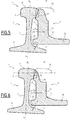
- the figures 5, 6 and 7 show sections of the switchgear made in different places (marked on the figure 1 ) of the distal part, when the contact between the needle 9 and the counter-needle 1 is made at the level of their mushrooms 2, 10. They show how the fungus 10 of the needle 9 is tapered by machining in the portion of the distal part of the needle rail, to form the part of the needle 9 which is called to come into contact with the counter rail 1, knowing that according to the invention, it is the only part of the rail d needle 9 which is necessarily machined, the remainder of needle 9 (the core 11 and the shoe 12 in the distal part being obtained from the initial rolling of the needle rail and the proximal part of needle 9 being, preferably, obtained only by forging the needle rail; however, the proximal part can also be machined in certain parts, in particular at the level of its heel.
- the figure 5 is carried out according to the reference VV of the figure 1 .
- the mushroom 10 of the needle 9 has been machined so as to make it tapered, the original outline of the upper part of the mushroom 10 being shown in dotted lines (as it is also on the figure 6 ).
- the machined mushroom 10 has an inclined contact face 21 extending the inclined contact face 15 of the proximal part, designed to adapt to the inclined contact face 16 of the counter-needle 1.
- the contact length between them represents at least 80% of the length of the inclined contact face 16 of the counter-needle.
- the contact length between them preferably represents at least 80% of the length of the inclined surface 16 of the counter-needle 1, and the clearance E between the end 22 of the shoe 18 of the needle 9 and the counter-needle 1 is at least 2 mm, preferably 4 to 5 mm. This condition must also be observed on the entire distal portion of needle 9.
- the lateral spacing dimension A is defined as being the horizontal distance between, on the one hand, the end 22 of the shoe 18 of the needle turned towards the counter-needle 1, on the other hand, the vertical axis YY 'of the needle rail.
- the lateral spacing dimension A is, in particular for the Russian profile, greater than 50 mm so that the conditions relating to the minimum moment of lateral inertia Iy of the needle 9 are more assuredly met, in the case of a needle 9 intended for a Russian switchboard network.
- the horizontal distance D between the end of the shoe 18 of the needle 9 facing the counter-needle 1 and the straight face 24 of the core 11 of the needle 9 facing the counter-needle 1 is preferably defined so that in the machined movable distal part of the needle 1, at the junction between the core 11 and the mushroom 10, the needle 9 has a minimum thickness B greater than or equal to 70% of the thickness of the core of the rail of the current track and of the counter-needle 1.
- D is preferably greater than or equal to 18mm.
- This minimum thickness B is found at the distal end of the needle 9 and is visible on the figure 7 .
- the goal is that the needle 9 which results from this machining and this possible forging of the needle rail certainly has sufficient inertia in comparison with those of the current track and the counter-needle 1.
- the dimension D is effectively, preferably, greater than 18 mm to help ensure that the conditions on the minimum lateral inertia Iy of the needle 9, which must be equal or greater than 130% of the lateral inertia of the counter-needle 1 and of the current track rail, are well filled.
- this dimension contributes to having a lateral inertia of the needle 9 at least equal to that of the counter needle 1.
- the figure 6 is carried out according to reference VI-VI of the figure 1 .
- the machining of the mushroom 10 has led to an even greater tapering thereof.
- Dimensions A and D are dimensions characteristic of the needle rail, and which are found on needle 1. Since shoe 12 is not machined, they keep the same values as in section VV of the figure 5 .
- the figure 7 is carried out according to reference VII-VII of the figure 1 .
- the machining of the mushroom 10 has led to an even greater tapering thereof, with an almost zero thickness of the mushroom 10 at its top 23.
- the dimensions A and D are dimensions characteristic of the needle rail, the shoe n '' not being machined, they keep the same value with respect to the sections according to VV and VI-VI of the figure 1 , visible respectively on Figures 5 and 6 .
- the difference F, F 'between the widths of the corresponding wings of the pads 4, 12 of the needle 9 on the one hand and of the counter-needle 1 and of the track rail current on the other hand is less than or equal to 50 mm, preferably less than or equal to 40 mm, better still less than or equal to 25 mm on each wing on the same side.
- the figure 8 highlights it, which shows what the said widths F and F 'correspond to.
- the profiles of the counter-needle 1 and the needle 9 are superimposed (at its proximal end) by making their rolling surfaces coincide, and the horizontal distances F, F 'between the ends of the wings of the pads 4 , 12 on each side are marked. It is these distances F, F 'which should preferably be 50 mm or less, the optimum being less than 25 mm.
- the purpose of this characteristic is to allow the forging of needle 9 directly from the current track rail.
- the figure 8 also highlights a preferred characteristic of the invention, according to which the core 3 of the counter-needle 1 is included, without overflow, in the core 11 of the needle rail 27, therefore of the needle 9, when the needle rail profiles 9 and the needle 1 are superimposed as indicated.
- the cross-sectional area of the needle 9 in its proximal portion is at least 15% greater than that of the counter-needle 1 and of the current track rail, and the forging of the forged part of the needle 9 has led to a reduction in the area of the forged part by a maximum of 30% compared to the corresponding part of the needle rail 1.
- the lateral inertia of the needle 9 at its tapered distal end, where its thickness is minimum, is preferably less than 25% less, better at most 17%, than the lateral inertia of the needle 9 at its proximal end connected to the current channel, and this in all the variants of the invention.
- the rectilinear surface 24 of the core of the needle begins from 55 mm, at most 75 mm, preferably from 60 mm to 70 mm below the top of the needle mushroom. It can therefore easily include arrangements, such as recesses, for the insertion of elements such as supports, fixings, stops.
Landscapes
- Engineering & Computer Science (AREA)
- Mechanical Engineering (AREA)
- Architecture (AREA)
- Civil Engineering (AREA)
- Structural Engineering (AREA)
- Forging (AREA)
- Railway Tracks (AREA)
- Medicines Containing Antibodies Or Antigens For Use As Internal Diagnostic Agents (AREA)
Claims (9)
- Eisenbahnknoten, umfassend eine Backenschiene (1) und eine aus einer Zungenschiene ausgebildete Schiene (9), jeweils umfassend einen Schienenkopf (2, 10), einen Schienensteg (3, 11) und einen Schienenfuß (4, 12), der aus Flügeln, die sich beiderseits des unteren Endes des Stegs (3, 11) erstrecken, besteht, wobei der Fuß (12) der Schiene (9) auf einem horizontalen Gleittisch (13) aufliegt, wobei die Backenschiene (1) und die Schiene (9) jeweils einen distalen und einen proximalen Teil aufweisen, wobei letzterer auf der Seite des an eine Schiene des Gleises angeschlossenen Fusses (12) der Schiene (9) angeordnet ist, wobei die Schienenköpfe (2, 10) der Backenschiene (1) und der Schiene (9) jeweils eine Lauffläche, die um mindestens 1/60, vorzugsweise 1/20 zur Horizontalen geneigt ist, und ein Verschleißprofil, das mit dem des Gleises identisch ist, aufweisen, wobei der Spielraum (E) zwischen dem Ende (22) des Fusses (12) der Schiene (9) und der Backenschiene (1) mindestens 2 mm, vorzugsweise 4 - 5 mm, beträgt, wenn die Schiene (9) an der Backenschiene (1) anliegt, und wobei, wenn die Schiene (9) an der Backenschiene (1) anliegt, die Länge der Kontaktfläche zwischen ihnen mindestens 80 % der Länge der geneigten Kontaktfläche (16) der Backenschiene (1) darstellt,
dadurch gekennzeichnet, dass der Schienenkopf (10) durch Fräsen der Zungenschiene verjüngt ist, und der distale Teil des Fusses (12) ohne Fräsen nur durch Laminierung ausgebildet ist, dass der distale Teil der Schiene (9) durch Schmieden oder durch Schmieden und Fräsen ausgebildet ist, dass die vertikale Trägheit (Ix) der Zungenschiene größer oder gleich 60 % der vertikalen Trägheit (Ix) der Backenschiene (1) und der Gleisschiene ist und
dass die minimale seitliche Trägheit (ly) der Schiene (9) gleich mindestens 100 %, insbesondere mindestens 130 %, vorzugsweise mindestens 140 % der minimalen seitlichen Trägheit (ly) der Backenschiene (1) und der Gleisschiene ist. - Eisenbahnknoten nach Anspruch 1, dadurch gekennzeichnet, dass der Schienenkopf (10) der Backenschiene, aus der die Schiene (9) ausgebildet ist, ein asymmetrisches Profil aufweist.
- Eisenbahnknoten nach Anspruch 1 oder 2, dadurch gekennzeichnet, dass die der Backenschiene (1) zugewandte Seite des Schienenkopfes (10) der Schiene (9) eine geneigte Kontaktfläche (15) aufweist, die mit einer auf der Backenschiene (1) angeordneten entsprechenden geneigten Kontaktfläche (16) zusammenwirkt, wenn die Schiene (9) an der Backenschiene (1) anliegt, wobei die geneigte Kontaktfläche (16) eine Breite (L) im Bereich von 0 bis höchstens 10 mm, vozugsweise 6 mm, aufweist.
- Eisenbahnknoten nach einem der Ansprüche 1 - 3, dadurch gekennzeichnet, dass die Neigung der Lauffläche der Backenschiene (1) mindestens zum Teil aus einer Neigung der Oberseite (7) einer horizontal (5) positionierten Stütze (6) resultiert, und auf der die Backenschiene (1) aufliegt.
- Eisenbahnknoten nach einem der Ansprüche 1 - 4, dadurch gekennzeichnet, dass der horizontale Abstand (D) zwischen dem der Backenschiene (1) zugewandten Ende des Fusses (18) der Schiene (9) und der der Backenschiene (1) zugewandten geraden Fläche (24) des Schienenstegs (11) der Schiene (9) derart definiert ist, dass im gefrästen beweglichen distalen Teil der Schiene (1) auf Höhe der Verbindungsstelle zwischen Steg (11) und Kopf (10) die Schiene (9) eine Mindestdicke (B) größer oder gleich 70 % der Dicke des Schienenstegs (3) des Gleises und der Dicke des Schienenstegs (3) der Backenschiene (1) aufweist.
- Eisenbahnknoten nach einem der Ansprüche 1 - 5, dadurch gekennzeichnet, dass die Gesamtbreite des Fusses (12) der Zungenschiene und somit auch der Schiene (9) gleich der des Fusses (4) der Backenschiene (1) ± 10 mm ist.
- Eisenbahnknoten nach einem der Ansprüche 1 - 6, dadurch gekennzeichnet, dass in dem Teil der Zungenschiene, die geschmiedet werden soll, um den proximalen Teil der Schiene (9) zu bilden, der Unterschied zwischen den Breiten der entsprechenden Flügel (18, 19) der Flüsse (12, 14) der Zungenschiene, und somit auch der Schiene (9) auf jedem Flügel vor dem Schmieden einerseits und der Gleisschiene andererseits kleiner oder gleich 50 mm, insbesondere kleiner oder gleich 40 mm, vorzugsweise kleiner oder gleich 25 mm ist.
- Eisenbahnknoten nach einem der Ansprüche 1 - 7, dadurch gekennzeichnet, dass, wenn die Querschnitte der Backenschiene (1) und der Zungenschiene (9) einander derart überlagert sind, dass ihre jeweiligen Laufflächen zusammentreffen, der Schienensteg (3) der Backenschiene (1) überstandslos im Schienensteg (11) der Zungenschiene (9) enthalten ist.
- Eisenbahnknoten nach einem der Ansprüche 1 - 8, dadurch gekennzeichnet, dass die seitliche Trägheit (ly) der Schiene (9) an ihrem verjüngten distalen Ende, wo ihre Dicke minimal ist, um höchstens 25 %, vorzugsweise höchstens 17 % kleiner als die seitliche Trägheit (ly) der Schiene (9) an dessen an das Gleis angeschlossenem proximalen Ende ist.
Priority Applications (1)
| Application Number | Priority Date | Filing Date | Title |
|---|---|---|---|
| PL16187591T PL3141448T3 (pl) | 2015-09-09 | 2016-09-07 | Urządzenie przełączające mające iglicę i opornicę |
Applications Claiming Priority (1)
| Application Number | Priority Date | Filing Date | Title |
|---|---|---|---|
| EA201500833A EA030076B1 (ru) | 2015-09-09 | 2015-09-09 | Стрелочный перевод, содержащий остряк и рамный рельс |
Publications (2)
| Publication Number | Publication Date |
|---|---|
| EP3141448A1 EP3141448A1 (de) | 2017-03-15 |
| EP3141448B1 true EP3141448B1 (de) | 2020-04-08 |
Family
ID=56893787
Family Applications (1)
| Application Number | Title | Priority Date | Filing Date |
|---|---|---|---|
| EP16187591.9A Active EP3141448B1 (de) | 2015-09-09 | 2016-09-07 | Weiche, die eine zunge und eine backenschiene umfasst |
Country Status (5)
| Country | Link |
|---|---|
| EP (1) | EP3141448B1 (de) |
| EA (1) | EA030076B1 (de) |
| HU (1) | HUE049476T2 (de) |
| LT (1) | LT3141448T (de) |
| PL (1) | PL3141448T3 (de) |
Families Citing this family (3)
| Publication number | Priority date | Publication date | Assignee | Title |
|---|---|---|---|---|
| CN107386017B (zh) * | 2017-06-12 | 2019-05-03 | 西南交通大学 | 道岔钢轨结构 |
| AT521128B1 (de) * | 2018-03-29 | 2021-01-15 | Voestalpine Weichensysteme Gmbh | Zungenschiene |
| AT521322B1 (de) * | 2018-06-12 | 2021-03-15 | Voestalpine Weichensysteme Gmbh | Backenschiene |
Family Cites Families (5)
| Publication number | Priority date | Publication date | Assignee | Title |
|---|---|---|---|---|
| SU1273424A1 (ru) * | 1982-12-30 | 1986-11-30 | Проектно-Технологическо-Конструкторское Бюро Главного Управления Пути Мпс Ссср | Остр к дл соединений и пересечений железнодорожного пути |
| FR2698110B1 (fr) * | 1992-11-16 | 1995-02-03 | Cogifer | Rail-aiguille perfectionné pour appareil de voie. |
| DE10046415C2 (de) * | 2000-09-18 | 2002-08-14 | Schreck Mieves Gmbh | Rillenschienen-Weichenvorrichtung |
| UA81372C2 (en) * | 2006-10-09 | 2007-12-25 | Ukrssec Energostal | Method for making switch blades |
| CN103924488B (zh) * | 2014-03-12 | 2016-07-13 | 中铁宝桥集团有限公司 | 城市轨道交通道岔尖轨及制作工艺 |
-
2015
- 2015-09-09 EA EA201500833A patent/EA030076B1/ru not_active IP Right Cessation
-
2016
- 2016-09-07 LT LTEP16187591.9T patent/LT3141448T/lt unknown
- 2016-09-07 PL PL16187591T patent/PL3141448T3/pl unknown
- 2016-09-07 EP EP16187591.9A patent/EP3141448B1/de active Active
- 2016-09-07 HU HUE16187591A patent/HUE049476T2/hu unknown
Non-Patent Citations (1)
| Title |
|---|
| None * |
Also Published As
| Publication number | Publication date |
|---|---|
| LT3141448T (lt) | 2020-07-27 |
| PL3141448T3 (pl) | 2020-09-07 |
| EP3141448A1 (de) | 2017-03-15 |
| EA201500833A1 (ru) | 2017-03-31 |
| HUE049476T2 (hu) | 2020-09-28 |
| EA030076B1 (ru) | 2018-06-29 |
Similar Documents
| Publication | Publication Date | Title |
|---|---|---|
| CA2589641C (fr) | Moule pour la soudure aluminothermique de rails de chemin de fer dont l'un, au moins est use | |
| EP3141448B1 (de) | Weiche, die eine zunge und eine backenschiene umfasst | |
| EP1564141B1 (de) | Flugzeugsitzschiene und deren Fertigungsverfahren | |
| CA2908867A1 (fr) | Croisement de rails prevu pour le croisement d'un rail de guidage avec un second rail | |
| EP0960045A1 (de) | Führungssystem entlang mindestens einer bodenschiene für eine achse eines strassenfahrzeugs | |
| EP0501183A1 (de) | Vorrichtung zur Wiederprofilierung von Eisenbahnschienen | |
| FR2725428A1 (fr) | Transporteur pousseur a palettes | |
| FR2543176A1 (fr) | Guide-fil pour machines a tricoter rectilignes | |
| EP2905195B1 (de) | Mobile messvorrichtung für ein schienenkopfprofil | |
| EP2500468B1 (de) | Vorrichtung zur Ausdehnung einer Führungsschiene | |
| EP3013665B1 (de) | Vorrichtung für eisenbahnradabnutzungsausgleich für eine lagerbüchse eines eisenbahndrehgestells | |
| FR3023862A1 (fr) | Lame de parquet, ensemble d'au moins deux telles lames et procede d'assemblage associe | |
| EP2998438B1 (de) | Gerät für eisenbahngleis | |
| EP0573702A1 (de) | Verfahren zum Herstellen eines Übergangssektors einer Eisenbahnschiene und so hergestellte Eisenbahnschiene | |
| FR2827879A1 (fr) | Rail a gorge pour voie ferree et utilisation d'un tel rail pour la realisation d'un reseau ferre en zone urbaine ou peri-urbaine | |
| EP1697593B1 (de) | Führungssystem für fahrzeuge | |
| EP1801023B1 (de) | Lagerungsbehälter mit Schubladen | |
| EP1217126B1 (de) | Gleis für ein schienengebundenes Fahrzeug und eine ein derartiges Gleis enthaltende Einrichtung | |
| FR3131340A1 (fr) | Elément de revêtement de sol à assemblage vertical | |
| FR2557054A1 (fr) | Dispositif de roulement et de guidage d'un funiculaire sur des rails | |
| EP3325719B1 (de) | Basisteil einer form zum verschweissen von metallschienen | |
| FR3165680A1 (fr) | Ensemble pour le freinage d’un véhicule ferroviaire | |
| CH675284A5 (en) | Linear bearing esp. for axial travel along shaft - consists of series of closed circuits containing balls which recirculate through them | |
| EP3907329A1 (de) | Vorrichtung zur befestigung einer schiene | |
| FR3002955A1 (fr) | Raidisseur pour voie ferree et procede de fabrication d'un tel raidisseur |
Legal Events
| Date | Code | Title | Description |
|---|---|---|---|
| PUAI | Public reference made under article 153(3) epc to a published international application that has entered the european phase |
Free format text: ORIGINAL CODE: 0009012 |
|
| STAA | Information on the status of an ep patent application or granted ep patent |
Free format text: STATUS: THE APPLICATION HAS BEEN PUBLISHED |
|
| AK | Designated contracting states |
Kind code of ref document: A1 Designated state(s): AL AT BE BG CH CY CZ DE DK EE ES FI FR GB GR HR HU IE IS IT LI LT LU LV MC MK MT NL NO PL PT RO RS SE SI SK SM TR |
|
| AX | Request for extension of the european patent |
Extension state: BA ME |
|
| STAA | Information on the status of an ep patent application or granted ep patent |
Free format text: STATUS: REQUEST FOR EXAMINATION WAS MADE |
|
| 17P | Request for examination filed |
Effective date: 20170410 |
|
| RBV | Designated contracting states (corrected) |
Designated state(s): AL AT BE BG CH CY CZ DE DK EE ES FI FR GB GR HR HU IE IS IT LI LT LU LV MC MK MT NL NO PL PT RO RS SE SI SK SM TR |
|
| STAA | Information on the status of an ep patent application or granted ep patent |
Free format text: STATUS: EXAMINATION IS IN PROGRESS |
|
| 17Q | First examination report despatched |
Effective date: 20180405 |
|
| GRAP | Despatch of communication of intention to grant a patent |
Free format text: ORIGINAL CODE: EPIDOSNIGR1 |
|
| STAA | Information on the status of an ep patent application or granted ep patent |
Free format text: STATUS: GRANT OF PATENT IS INTENDED |
|
| INTG | Intention to grant announced |
Effective date: 20191108 |
|
| GRAS | Grant fee paid |
Free format text: ORIGINAL CODE: EPIDOSNIGR3 |
|
| GRAA | (expected) grant |
Free format text: ORIGINAL CODE: 0009210 |
|
| STAA | Information on the status of an ep patent application or granted ep patent |
Free format text: STATUS: THE PATENT HAS BEEN GRANTED |
|
| AK | Designated contracting states |
Kind code of ref document: B1 Designated state(s): AL AT BE BG CH CY CZ DE DK EE ES FI FR GB GR HR HU IE IS IT LI LT LU LV MC MK MT NL NO PL PT RO RS SE SI SK SM TR |
|
| REG | Reference to a national code |
Ref country code: CH Ref legal event code: EP Ref country code: AT Ref legal event code: REF Ref document number: 1254004 Country of ref document: AT Kind code of ref document: T Effective date: 20200415 |
|
| REG | Reference to a national code |
Ref country code: DE Ref legal event code: R096 Ref document number: 602016033418 Country of ref document: DE |
|
| REG | Reference to a national code |
Ref country code: IE Ref legal event code: FG4D Free format text: LANGUAGE OF EP DOCUMENT: FRENCH |
|
| REG | Reference to a national code |
Ref country code: NL Ref legal event code: MP Effective date: 20200408 |
|
| REG | Reference to a national code |
Ref country code: HU Ref legal event code: AG4A Ref document number: E049476 Country of ref document: HU |
|
| PG25 | Lapsed in a contracting state [announced via postgrant information from national office to epo] |
Ref country code: NL Free format text: LAPSE BECAUSE OF FAILURE TO SUBMIT A TRANSLATION OF THE DESCRIPTION OR TO PAY THE FEE WITHIN THE PRESCRIBED TIME-LIMIT Effective date: 20200408 Ref country code: SE Free format text: LAPSE BECAUSE OF FAILURE TO SUBMIT A TRANSLATION OF THE DESCRIPTION OR TO PAY THE FEE WITHIN THE PRESCRIBED TIME-LIMIT Effective date: 20200408 Ref country code: NO Free format text: LAPSE BECAUSE OF FAILURE TO SUBMIT A TRANSLATION OF THE DESCRIPTION OR TO PAY THE FEE WITHIN THE PRESCRIBED TIME-LIMIT Effective date: 20200708 Ref country code: GR Free format text: LAPSE BECAUSE OF FAILURE TO SUBMIT A TRANSLATION OF THE DESCRIPTION OR TO PAY THE FEE WITHIN THE PRESCRIBED TIME-LIMIT Effective date: 20200709 Ref country code: IS Free format text: LAPSE BECAUSE OF FAILURE TO SUBMIT A TRANSLATION OF THE DESCRIPTION OR TO PAY THE FEE WITHIN THE PRESCRIBED TIME-LIMIT Effective date: 20200808 Ref country code: PT Free format text: LAPSE BECAUSE OF FAILURE TO SUBMIT A TRANSLATION OF THE DESCRIPTION OR TO PAY THE FEE WITHIN THE PRESCRIBED TIME-LIMIT Effective date: 20200817 Ref country code: FI Free format text: LAPSE BECAUSE OF FAILURE TO SUBMIT A TRANSLATION OF THE DESCRIPTION OR TO PAY THE FEE WITHIN THE PRESCRIBED TIME-LIMIT Effective date: 20200408 |
|
| PGFP | Annual fee paid to national office [announced via postgrant information from national office to epo] |
Ref country code: LT Payment date: 20200825 Year of fee payment: 5 Ref country code: LU Payment date: 20200817 Year of fee payment: 5 |
|
| REG | Reference to a national code |
Ref country code: AT Ref legal event code: MK05 Ref document number: 1254004 Country of ref document: AT Kind code of ref document: T Effective date: 20200408 |
|
| PG25 | Lapsed in a contracting state [announced via postgrant information from national office to epo] |
Ref country code: RS Free format text: LAPSE BECAUSE OF FAILURE TO SUBMIT A TRANSLATION OF THE DESCRIPTION OR TO PAY THE FEE WITHIN THE PRESCRIBED TIME-LIMIT Effective date: 20200408 Ref country code: HR Free format text: LAPSE BECAUSE OF FAILURE TO SUBMIT A TRANSLATION OF THE DESCRIPTION OR TO PAY THE FEE WITHIN THE PRESCRIBED TIME-LIMIT Effective date: 20200408 Ref country code: BG Free format text: LAPSE BECAUSE OF FAILURE TO SUBMIT A TRANSLATION OF THE DESCRIPTION OR TO PAY THE FEE WITHIN THE PRESCRIBED TIME-LIMIT Effective date: 20200708 |
|
| PGFP | Annual fee paid to national office [announced via postgrant information from national office to epo] |
Ref country code: LV Payment date: 20200820 Year of fee payment: 5 Ref country code: HU Payment date: 20200827 Year of fee payment: 5 |
|
| PG25 | Lapsed in a contracting state [announced via postgrant information from national office to epo] |
Ref country code: AL Free format text: LAPSE BECAUSE OF FAILURE TO SUBMIT A TRANSLATION OF THE DESCRIPTION OR TO PAY THE FEE WITHIN THE PRESCRIBED TIME-LIMIT Effective date: 20200408 |
|
| REG | Reference to a national code |
Ref country code: DE Ref legal event code: R097 Ref document number: 602016033418 Country of ref document: DE |
|
| PG25 | Lapsed in a contracting state [announced via postgrant information from national office to epo] |
Ref country code: IT Free format text: LAPSE BECAUSE OF FAILURE TO SUBMIT A TRANSLATION OF THE DESCRIPTION OR TO PAY THE FEE WITHIN THE PRESCRIBED TIME-LIMIT Effective date: 20200408 Ref country code: RO Free format text: LAPSE BECAUSE OF FAILURE TO SUBMIT A TRANSLATION OF THE DESCRIPTION OR TO PAY THE FEE WITHIN THE PRESCRIBED TIME-LIMIT Effective date: 20200408 Ref country code: CZ Free format text: LAPSE BECAUSE OF FAILURE TO SUBMIT A TRANSLATION OF THE DESCRIPTION OR TO PAY THE FEE WITHIN THE PRESCRIBED TIME-LIMIT Effective date: 20200408 Ref country code: AT Free format text: LAPSE BECAUSE OF FAILURE TO SUBMIT A TRANSLATION OF THE DESCRIPTION OR TO PAY THE FEE WITHIN THE PRESCRIBED TIME-LIMIT Effective date: 20200408 Ref country code: ES Free format text: LAPSE BECAUSE OF FAILURE TO SUBMIT A TRANSLATION OF THE DESCRIPTION OR TO PAY THE FEE WITHIN THE PRESCRIBED TIME-LIMIT Effective date: 20200408 Ref country code: DK Free format text: LAPSE BECAUSE OF FAILURE TO SUBMIT A TRANSLATION OF THE DESCRIPTION OR TO PAY THE FEE WITHIN THE PRESCRIBED TIME-LIMIT Effective date: 20200408 Ref country code: EE Free format text: LAPSE BECAUSE OF FAILURE TO SUBMIT A TRANSLATION OF THE DESCRIPTION OR TO PAY THE FEE WITHIN THE PRESCRIBED TIME-LIMIT Effective date: 20200408 Ref country code: SM Free format text: LAPSE BECAUSE OF FAILURE TO SUBMIT A TRANSLATION OF THE DESCRIPTION OR TO PAY THE FEE WITHIN THE PRESCRIBED TIME-LIMIT Effective date: 20200408 |
|
| PLBE | No opposition filed within time limit |
Free format text: ORIGINAL CODE: 0009261 |
|
| STAA | Information on the status of an ep patent application or granted ep patent |
Free format text: STATUS: NO OPPOSITION FILED WITHIN TIME LIMIT |
|
| PG25 | Lapsed in a contracting state [announced via postgrant information from national office to epo] |
Ref country code: SK Free format text: LAPSE BECAUSE OF FAILURE TO SUBMIT A TRANSLATION OF THE DESCRIPTION OR TO PAY THE FEE WITHIN THE PRESCRIBED TIME-LIMIT Effective date: 20200408 |
|
| 26N | No opposition filed |
Effective date: 20210112 |
|
| REG | Reference to a national code |
Ref country code: DE Ref legal event code: R119 Ref document number: 602016033418 Country of ref document: DE |
|
| PG25 | Lapsed in a contracting state [announced via postgrant information from national office to epo] |
Ref country code: MC Free format text: LAPSE BECAUSE OF FAILURE TO SUBMIT A TRANSLATION OF THE DESCRIPTION OR TO PAY THE FEE WITHIN THE PRESCRIBED TIME-LIMIT Effective date: 20200408 |
|
| REG | Reference to a national code |
Ref country code: CH Ref legal event code: PL |
|
| GBPC | Gb: european patent ceased through non-payment of renewal fee |
Effective date: 20200907 |
|
| PG25 | Lapsed in a contracting state [announced via postgrant information from national office to epo] |
Ref country code: SI Free format text: LAPSE BECAUSE OF FAILURE TO SUBMIT A TRANSLATION OF THE DESCRIPTION OR TO PAY THE FEE WITHIN THE PRESCRIBED TIME-LIMIT Effective date: 20200408 |
|
| REG | Reference to a national code |
Ref country code: BE Ref legal event code: MM Effective date: 20200930 |
|
| PG25 | Lapsed in a contracting state [announced via postgrant information from national office to epo] |
Ref country code: DE Free format text: LAPSE BECAUSE OF NON-PAYMENT OF DUE FEES Effective date: 20210401 |
|
| PG25 | Lapsed in a contracting state [announced via postgrant information from national office to epo] |
Ref country code: LI Free format text: LAPSE BECAUSE OF NON-PAYMENT OF DUE FEES Effective date: 20200930 Ref country code: GB Free format text: LAPSE BECAUSE OF NON-PAYMENT OF DUE FEES Effective date: 20200907 Ref country code: IE Free format text: LAPSE BECAUSE OF NON-PAYMENT OF DUE FEES Effective date: 20200907 Ref country code: CH Free format text: LAPSE BECAUSE OF NON-PAYMENT OF DUE FEES Effective date: 20200930 Ref country code: BE Free format text: LAPSE BECAUSE OF NON-PAYMENT OF DUE FEES Effective date: 20200930 |
|
| REG | Reference to a national code |
Ref country code: LT Ref legal event code: MM4D Effective date: 20210907 |
|
| PG25 | Lapsed in a contracting state [announced via postgrant information from national office to epo] |
Ref country code: TR Free format text: LAPSE BECAUSE OF FAILURE TO SUBMIT A TRANSLATION OF THE DESCRIPTION OR TO PAY THE FEE WITHIN THE PRESCRIBED TIME-LIMIT Effective date: 20200408 Ref country code: MT Free format text: LAPSE BECAUSE OF FAILURE TO SUBMIT A TRANSLATION OF THE DESCRIPTION OR TO PAY THE FEE WITHIN THE PRESCRIBED TIME-LIMIT Effective date: 20200408 Ref country code: LV Free format text: LAPSE BECAUSE OF NON-PAYMENT OF DUE FEES Effective date: 20210907 Ref country code: CY Free format text: LAPSE BECAUSE OF FAILURE TO SUBMIT A TRANSLATION OF THE DESCRIPTION OR TO PAY THE FEE WITHIN THE PRESCRIBED TIME-LIMIT Effective date: 20200408 |
|
| PG25 | Lapsed in a contracting state [announced via postgrant information from national office to epo] |
Ref country code: MK Free format text: LAPSE BECAUSE OF FAILURE TO SUBMIT A TRANSLATION OF THE DESCRIPTION OR TO PAY THE FEE WITHIN THE PRESCRIBED TIME-LIMIT Effective date: 20200408 |
|
| PG25 | Lapsed in a contracting state [announced via postgrant information from national office to epo] |
Ref country code: LU Free format text: LAPSE BECAUSE OF NON-PAYMENT OF DUE FEES Effective date: 20210907 Ref country code: LT Free format text: LAPSE BECAUSE OF NON-PAYMENT OF DUE FEES Effective date: 20210907 Ref country code: HU Free format text: LAPSE BECAUSE OF NON-PAYMENT OF DUE FEES Effective date: 20210908 |
|
| P01 | Opt-out of the competence of the unified patent court (upc) registered |
Effective date: 20230606 |
|
| PGFP | Annual fee paid to national office [announced via postgrant information from national office to epo] |
Ref country code: PL Payment date: 20250825 Year of fee payment: 10 |
|
| PGFP | Annual fee paid to national office [announced via postgrant information from national office to epo] |
Ref country code: FR Payment date: 20250812 Year of fee payment: 10 |