EP3141449B1 - Rail profile monitoring, e.g. geometry of the frogs - Google Patents
Rail profile monitoring, e.g. geometry of the frogs Download PDFInfo
- Publication number
- EP3141449B1 EP3141449B1 EP16166281.2A EP16166281A EP3141449B1 EP 3141449 B1 EP3141449 B1 EP 3141449B1 EP 16166281 A EP16166281 A EP 16166281A EP 3141449 B1 EP3141449 B1 EP 3141449B1
- Authority
- EP
- European Patent Office
- Prior art keywords
- light
- rail
- lines
- millimeter
- light lines
- Prior art date
- Legal status (The legal status is an assumption and is not a legal conclusion. Google has not performed a legal analysis and makes no representation as to the accuracy of the status listed.)
- Active
Links
Images


Classifications
-
- B—PERFORMING OPERATIONS; TRANSPORTING
- B61—RAILWAYS
- B61L—GUIDING RAILWAY TRAFFIC; ENSURING THE SAFETY OF RAILWAY TRAFFIC
- B61L23/00—Control, warning or like safety means along the route or between vehicles or trains
- B61L23/04—Control, warning or like safety means along the route or between vehicles or trains for monitoring the mechanical state of the route
- B61L23/042—Track changes detection
- B61L23/045—Rail wear
-
- B—PERFORMING OPERATIONS; TRANSPORTING
- B61—RAILWAYS
- B61L—GUIDING RAILWAY TRAFFIC; ENSURING THE SAFETY OF RAILWAY TRAFFIC
- B61L23/00—Control, warning or like safety means along the route or between vehicles or trains
- B61L23/04—Control, warning or like safety means along the route or between vehicles or trains for monitoring the mechanical state of the route
- B61L23/042—Track changes detection
- B61L23/047—Track or rail movements
Definitions
- This invention relates to an apparatus and method for monitoring wear and deformation of a turnout (also called switch and crossing) of a railway or tramway line.
- Prior art document WO 1/86227 A1 discloses a method for measuring track geometry using multiple lasers and cameras spaced along the length of the rail to render the measurements insensitive to oscillations of the measuring vehicle.
- Laser measurement systems e.g. measuring distance or a profile of e.g. the rail head or different track component, such as triangulation sensors (one dimension measurement) or light sectioning sensors (a two dimensional extension of the laser triangulation method, thus a two dimensional measurement), offer an accuracy in the range of several micrometers at a bandwidth of 10 kHz or even higher. Their speed is therefore sufficient to measure from moving platforms (e.g. a measuring train), but it is difficult or often impossible to guide the platform with a precision comparable to the measurement accuracy. To compensate this uncertainty of the relative position of the measurement system, from practice there is known to apply an acceleration sensor to establish a virtual reference line for the value measured.
- a typical example known from prior art practice is the corrugation measurement of the rail head with a spectral accuracy better than 10 mu m from a running train superimposed to a vertical movement of about 10 mm.
- the vehicle speed is preferably at least 40 or 60 km/h.
- Sunlight interference and blooming effects preferably need be removed, e.g. by one or more protection systems (camera technology, pulsed laser and camera acquisition synchronized, interferential filters and software filters).
- the main object of the monitoring system is to give integrated indications to the track maintenance responsible for planning the interventions for the short and long term.
- the system preferably is able to detect and quantify all the key WEAR PARAMETERS describing the qualitative status of the infrastructure (vertical wear, transversal wear, multi-point wear, gauge).
- Laser light is an example of an optically coherent radiation beam.
- the camera is an example of a light receiving unit for monitoring the focusing projection of the radiation beam on the object of interest and converts the radiation, reflected by the object, received on a measurement surface in the receiving unit into electrical signals which are entered into the connected computer.
- a lens e.g. Fresnel lens, is located between the object ad the camera for focusing the radiation from the object on the measurement surface of the camera.
- An object of the invention is one or more of the following: a further improvement in an attempt to sufficiently eliminate the interference of the horizontal and/or vertical oscillating movement (caused by i.a. the fact that the railway track is not perfectly straight, however in stead undulates) of the measuring train, carrying the measuring system, with the measurement results; to measure the wear or deformation of the turnout; to measure parameters of a frog of a turnout of a railway track without any mechanical contact with the frog and without the need to use mechanical centring devices; to acquire information relating to the actual profile of the frog, its degree of wear and its vertical and transverse deformation; to be able to accurately locate the location of the measurements, particularly relative to a reference point; to effect the measurements while insensitive to oscillation and deformation of the vehicle on which the apparatus is mounted; to obtain desired results from measurements in real time; to be able to conduct the measurements at a high velocity of at least 10 or 20 km/hr of the measuring train.
- This object is obtained by the invention such that the inaccuracy of a rail profile measurement is less than 0.1 millimeter.
- the invention concerns a method for geometry measurement of the frog of a turnout of a railway track as defined in claim 1.
- the invention concerns a method designed to provide one or more of the following: emit by its light sources five or more light beams, designed to be projected as spaced or overlapping light points or lines or spots onto an object of interest; at least a number and preferably substantially all of these light beams are emitted such that during advancement of the measuring train these light beams are projected successively onto the same area of the object and/or their light lines successively cover the same area of the object; during train advancement the light beams and/or their light lines move along the object, one behind the other; the light beams are substantially simultaneously projected onto the object; light lines are provided by five or more light beams; the object of interest is of the railway track, specifically a frog preferably simultaneously detect these projections by a plurality of cameras; the data from these cameras is entered into a computer connected to and common to these cameras; the computer determines from this data a correction factor which is dependent from the horizontal and/or vertical oscillating movement of the measuring train and which correction factor is applied to computer calculations for a geometric feature of interest of the measured track
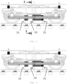
- the five light lines are applied in a pattern including one or more of the following (in the following "light line” also means “light point” or “light spot”) : spaced in longitudinal direction of the object, e.g. rail; close spacing between two adjacent light lines at least 10 millimeter and not more than 50 millimeter, e.g. approximately 30 millimeter or a single sample distance; wide spacing between two adjacent light lines at least 400 millimeter and not more than 800 millimeter, e.g. approximately 600 millimeter; spacing between the two outermost light not more than 1400 millimeter, e.g.
- a light line approximately 1200 millimeter; a light line approximately centrally between two other light lines; two light lines with close spacing, separated from the other light lines by at least the wide spacing; two sets, each of two light lines with close spacing, preferably wherein these two sets are mutually separated by at least the wide spacing; a light line separated from the other light lines by at least the wide spacing; the at least five spaced light lines are present as two sets (which light lines could be named “reference light lines”) and one individual light line (which could be named "accuracy light line”).
- a light line could include two or more light lines (e.g. each created by an individual light emitter, e.g. laser) which are exactly or virtually exactly mutually overlapping or precisely registered such that they are detected by the associated sensor as a single line. This is the case for the accuracy light line.
- the individual light lines could be spaced longitudinally or differ in frequency to avoid interference, e.g. as disclosed in EP2485010 .
- the light lines are associated with a sensor, two light lines having the close spacing are associated with a single sensor, such that the sensor (a camera) simultaneously detects both light lines, obviously wherein these light lines are projected at the light detecting part (e.g. the light sensitive matrix) of the sensor at different locations such that they are detected separately and can be discriminated by the sensor.
- the sensor a camera
- the width of a light line (as measured in longitudinal direction of the rail) is preferably smaller than 20 or 10 or 5 millimeter and/or is substantially constant along its length.
- the light line has preferably a green or red color.
- the optical axis of the imaging device including a, preferably flat, light detection element, makes a fixed angle (preferably at least 10 and/or not more than 50 degrees, e.g. approximately 30 degrees) relative to the emitting direction of the associated laser device while the imaging device and the associated laser device have mutually fixed locations.
- a light line could be associated with two or more sensors (e.g. each being a profile camera), according to the invention this is the light line for which the wide spacing with all the other light lines applies and this accuracy light line is provided by at least two light emitters, e.g. lasers.
- the accuracy light line is associated with a group of two or three or four cameras such that in an embodiment the accuracy light line projected on a stock or running or different rail is simultaneously scanned by a group of at least two or three or four cameras.
- the apparatus is provided with four cameras (two groups of two each) or even eight cameras (two groups of four each) in a preferred embodiment, to simultaneously monitor the accuracy light line projected on both opposite rails of the same track.
- At least one or at least two cameras are located at both sides of the associated rail and monitor said rail obliquely from above.
- the location transverse to the longitudinal direction of the rail and/or the angle of inclination of the optical axis of the cameras at the same side of the associated rail mutually differs, preferably by at least 10 or 20 millimeter and 10 or 20 degrees, respectively.
- the field of vision of a camera has overlapping edges with the field of vision of an adjacent camera. More preferably, the field of vision of a camera has only partly overlap, preferably not more than 20% or 50% overlap, with the field of vision of an adjacent camera at the same (one) side of the associated running or stock or different rail; (and/)or the field of vision of a camera has substantially complete overlap with the field of vision of an adjacent camera at the same (other) side of the associated running or stock or different rail.
- the cameras associated with the one or other running or stock rail provide a common field of vision such that simultaneously the head of the stock or running rail and associated point blade or check rail or wing rail over its complete top and complete sides and a part of the stock or running rail and associated point blade or check rail or wing rail at least 30 or 50 millimeter below the top of the head, such as part of the foot at the bottom of the relevant rail, are scanned.
- the point blade this applies preferably both in its position bearing against the stock rail and its position moved to a maximum distance from the stock rail.
- the cameras are preferably connected directly to the frame grabber boards of the measurement computer. In this way images are acquired that are used to calculate the rail profile, particularly of the head and fragments of foot and web.
- the distance between a vision module and the relevant rail measures between 50 and 750 millimeter, particularly between 200 and 400 millimeter.
- Each emitter and receiver is dedicated to a single rail; each emitter and receiver has a fixed optical axis; each emitter and receiver is supported by or suspended from a bogy or different part of the measuring train.
- one or more of the following parameters can also be calculated: rail head wear (vertical, horizontal, wear angle); slope of rails; track gauge; guiding rail groove width; width of the crossing nose groove; guiding width; groove width between the switch blade and the reaction rail.
- rail head wear vertical, horizontal, wear angle
- slope of rails track gauge
- guiding rail groove width width of the crossing nose groove
- guiding width groove width between the switch blade and the reaction rail.
- part of a system or method for measuring a rail profile by optical triangulation through optical detection systems operating by optical triangulation and moving along the rail at a movement speed comprising respective, preferably pairs, of light emitting devices, e.g. lasers, and optical reading devices, e.g.
- camera's including the steps of moving said optical detection systems along said rail at a movement speed, and lighting, preferably opposite, sides of the rail through the respective light emitting lasers, for projecting against said sides respective light spots adapted to generate respective optically detectable, preferably semi, profiles, preferably combinable, to obtain a measurement of the profile of a section of the rail, and detecting said semi-profiles through the respective optical reading devices; comprising a correcting system configured for measuring spatial variations of an optical detection system by optical triangulation with respect to the object, e.g.
- correcting the spatial position of at least one of the semi-profiles of a side through the values of the measured shifts through the correcting system comprising cameras which operate by reading the image rows in a synchronous manner; the system comprises means configured for implementing the method; triangulation also means light sectioning.
- the measuring device is arranged on a measuring train travelling on or along the track; the device includes essentially a light emitting device adapted to emit a light blade onto a plane which could be substantially orthogonal to the longitudinal axis of the rail; Further, preferably one or more of the following applies: an acquisition device adapted to acquire an image containing a light row or light line generated by the intersection between the light blade and the rail; a processing module adapted to process the light line contained in the image to determine, according to the light line itself, a value correlated to the dimension of the rail; the light emitting device is arranged on the vehicle so as to be positioned over the rail and includes, e.g., a laser emitter and preferably an optical focusing assembly including a series of prisms and focusing lenses properly positioned and oriented with respect to the laser emitter to transform the focused beam into the light blade; the optical focusing assembly is capable of transforming the focused beam into the light blade having an opening angle between 20 degrees and 120 degrees so as to be able to intersect the external surface of the
- the monitoring device includes a device adapted to detect the geographic position of the detecting vehicle instant-by-instant, so as to identify, on the basis of the determined geographic position, the section of track on which the vehicle is travelling; this could include a GPS receiver (or a similar wireless operating positioning system) and/or an odometer or shaft encoder, and a memory containing, for each position, the data related to the corresponding track and to the particulars at the track; the method includes: emitting the light blade with an angular opening so as to intersect the rail head; acquiring the image containing the light line generated by the intersection of the light blade on the track; processing the image containing the light line so as to determine a feature of interest, e.g.
- the method includes extrapolating the external contour of the rail head from the plurality of at least five light lines spaced along the track and provided by a plurality, e.g. equal number of laser devices; comparing this extrapolated contour and a sample contour stored in the memory module; if there is a difference between these two contours, calculating a correction factor from this difference and correcting the extrapolated contour by the correction factor.
- control module is configured for actuating the laser emitters to emit the laser radiation kept switched on by each laser emitter for a time of exposure which determines the lighting of a section of length of the object; a laser emitter-camera pair obtains an image of a semi-profile for a period of exposure; the one emitter switches off before another emitter switches on, e.g.
- a digital camera a camera which operates at a high speed (normally greater than 400 frames per second); a camera operates to read all the image rows in a synchronous manner; a camera speed of acquisition of 700 images per second, processing 500 rows per image, for example using an FCAM DMA camera; emitters adapted to produce beams at the same wavelength; semiconductor lasers; the period of exposure varies between 0.2 and 3 milliseconds; CMOS or CCD camera; laser power between 4 and 40W;
- the invention provides a method for the contact less dynamic recording of the profile of a frog of a turnout to determine its condition, such as wear or deformation, comprising at least five light beams from e.g. a laser device are projected onto an area of the rail facing the opposite rail.
- the laser device is moved along the rail and the light reflected from said area of the rail is focused onto a flat light detection element of an imaging device of which the optical axis makes a fixed angle relative to the emitting direction of the laser device while the imaging device and the laser device have mutually fixed locations such that the signal coming from the light detection element is processed in a computer processor on the basis of a triangulation procedure or light sectioning procedure to detect the distance between the imaging device and the rail, the signal from preferably at least two, three or four vision modules, which preferably form a single or virtually single projection plane directed onto the rail, is applied, means for correcting the spatial position of a measured object profile through the values of a track measuring system shift measuring means.
Landscapes
- Engineering & Computer Science (AREA)
- Mechanical Engineering (AREA)
- Length Measuring Devices By Optical Means (AREA)
- Machines For Laying And Maintaining Railways (AREA)
Applications Claiming Priority (1)
| Application Number | Priority Date | Filing Date | Title |
|---|---|---|---|
| NL2014681 | 2015-04-20 |
Publications (3)
| Publication Number | Publication Date |
|---|---|
| EP3141449A1 EP3141449A1 (en) | 2017-03-15 |
| EP3141449C0 EP3141449C0 (en) | 2025-07-02 |
| EP3141449B1 true EP3141449B1 (en) | 2025-07-02 |
Family
ID=57793772
Family Applications (1)
| Application Number | Title | Priority Date | Filing Date |
|---|---|---|---|
| EP16166281.2A Active EP3141449B1 (en) | 2015-04-20 | 2016-04-20 | Rail profile monitoring, e.g. geometry of the frogs |
Country Status (3)
| Country | Link |
|---|---|
| EP (1) | EP3141449B1 (pl) |
| NL (1) | NL2016637B1 (pl) |
| PL (1) | PL3141449T3 (pl) |
Families Citing this family (16)
| Publication number | Priority date | Publication date | Assignee | Title |
|---|---|---|---|---|
| CN107621229B (zh) * | 2017-10-23 | 2023-05-30 | 福州大学 | 基于面阵黑白相机的实时铁路轨道宽度测量系统及方法 |
| IT201800002756A1 (it) * | 2018-02-16 | 2019-08-16 | Easy Scander Srl | Sistema di rilevamento senza contatto di profili ferroviari |
| CN110243326B (zh) * | 2019-05-27 | 2024-04-30 | 北京全路通信信号研究设计院集团有限公司 | 一种铁路道岔尖轨不足位移检测装置及方法 |
| NL2023276B1 (en) * | 2019-06-07 | 2021-01-11 | Fnv Ip Bv | A track monitoring system |
| JP6682087B1 (ja) * | 2019-07-09 | 2020-04-15 | 朝日航洋株式会社 | 軌道中心計測装置および軌道中心計測方法 |
| CN110497930A (zh) * | 2019-08-06 | 2019-11-26 | 广州市奥特创通测控技术有限公司 | 一种全图像铁路道岔在线集成检测装置及方法 |
| CN111121662A (zh) * | 2020-01-13 | 2020-05-08 | 成都华瑞智创轨道交通科技有限公司 | 一种车载式轨道廓形与不平顺检测装置 |
| CN113776457B (zh) * | 2021-08-31 | 2023-08-08 | 中国铁道科学研究院集团有限公司 | 基于虚实结合的曲线段钢轨轮廓测量误差修正方法及装置 |
| CN114964046B (zh) * | 2022-06-21 | 2023-06-02 | 湖南科天健光电技术有限公司 | 钢轨廓形的测量方法、装置、设备及介质 |
| CN115289991B (zh) * | 2022-09-27 | 2023-01-13 | 武汉天宝耐特科技有限公司 | 地铁轨道形变监测方法、装置及电子设备 |
| CN115593462A (zh) * | 2022-10-17 | 2023-01-13 | 哈尔滨市科佳通用机电股份有限公司(Cn) | 一种地铁轨道几何形位参数动态检测系统及方法 |
| CN116923478A (zh) * | 2023-03-03 | 2023-10-24 | 浙江银轮智能装备有限公司 | 一种距离检测单元及轨道检测设备 |
| CN116923477B (zh) * | 2023-03-03 | 2025-08-01 | 浙江天台祥和智能装备有限公司 | 轨道检测单元及检测设备 |
| CN116952161A (zh) * | 2023-07-28 | 2023-10-27 | 北京汇众思壮图像技术有限公司 | 一种基于棱镜分光技术的抗阳光干扰的接触网几何参数检测装置 |
| CN117657230A (zh) * | 2023-11-23 | 2024-03-08 | 浙江银轮智能装备有限公司 | 轨道几何参数检测设备 |
| CN118424236B (zh) * | 2024-07-04 | 2024-10-11 | 宁波中车时代传感技术有限公司 | 一种基于线激光弦线的纵向水平检测装置 |
Family Cites Families (10)
| Publication number | Priority date | Publication date | Assignee | Title |
|---|---|---|---|---|
| DE19510560A1 (de) | 1995-03-23 | 1996-09-26 | Misoph Rotraud | Meßvorrichtung zur berührungsfreien Vermessung des Schienenprofils |
| SE0000746L (sv) | 2000-03-07 | 2001-06-11 | Laser Level Nordic Ab | Anordning och förfarande för mätning och sammanställning av normavvikelser under användande av ett referenssystem bildat mellan en första och en andra inbördes rörlig sänd- respektive mottagningsenhet |
| ITVE20000023A1 (it) * | 2000-05-12 | 2001-11-12 | Tecnogamma S A S Di Zanin E & | Apparecchiatura laser per il controllo delle rotaie di una linea ferrotramviaria. |
| US6618155B2 (en) * | 2000-08-23 | 2003-09-09 | Lmi Technologies Inc. | Method and apparatus for scanning lumber and other objects |
| EP1391690B1 (en) * | 2002-08-14 | 2015-07-01 | 3D Scanners Ltd | Optical probe for measuring features of an object and methods therefor |
| ITTO20070384A1 (it) | 2007-06-01 | 2008-12-02 | Mer Mec S P A | Apparecchio e metodo per il monitoraggio di un binario |
| NL2003527C2 (en) | 2008-09-23 | 2011-05-19 | Volkerrail Nederland B V | Monitoring a turnout of a railway or tramway line. |
| DE102010019618A1 (de) | 2010-05-06 | 2011-11-10 | Alstom Transport Sa | Vorrichtung und Verfahren zur Bestimmung der Welligkeit von Oberflächen |
| EP2485010B1 (en) | 2011-02-03 | 2014-08-06 | DMA S.r.l. | Method for measuring a rail profile by optical triangulation and corresponding measuring system |
| EP2714487A1 (en) * | 2011-05-24 | 2014-04-09 | Board Of Regents Of The University Of Nebraska | Vision system for imaging and measuring rail deflection |
-
2016
- 2016-04-19 NL NL2016637A patent/NL2016637B1/en active
- 2016-04-20 EP EP16166281.2A patent/EP3141449B1/en active Active
- 2016-04-20 PL PL16166281.2T patent/PL3141449T3/pl unknown
Also Published As
| Publication number | Publication date |
|---|---|
| NL2016637A (en) | 2016-10-24 |
| NL2016637B1 (en) | 2018-08-24 |
| EP3141449A1 (en) | 2017-03-15 |
| PL3141449T3 (pl) | 2025-09-01 |
| EP3141449C0 (en) | 2025-07-02 |
Similar Documents
| Publication | Publication Date | Title |
|---|---|---|
| EP3141449B1 (en) | Rail profile monitoring, e.g. geometry of the frogs | |
| EP2165915B1 (en) | Monitoring a turnout of a railway or tramway line | |
| US7036232B2 (en) | Apparatus for monitoring the rails of a railway or tramway line | |
| US20200398876A1 (en) | Debris deflection and removal method for an apparatus and method for gathering data from sensors oriented at an oblique angle relative to a railway track | |
| US9205850B2 (en) | Displacement detecting apparatus for railroad rails | |
| CA3222375C (en) | APPARATUS AND METHOD FOR CALCULATING THE CUTTING DIMENSIONS OF THE CROSS PLATE AND THE ABRASION OF THE RAIL SUPPORT AS A FUNCTION OF THE HEIGHT OF THE RAIL MUSHROOM | |
| US4180322A (en) | Interior measurement of enclosed spaces | |
| EP2485010B1 (en) | Method for measuring a rail profile by optical triangulation and corresponding measuring system | |
| KR102513815B1 (ko) | 자동화된 선로 이상 탐지 방법 및 그 장치 | |
| JP6317621B2 (ja) | 車両に装備された車輪の三次元形状測定方法と車両に装備された車輪の三次元形状測定装置 | |
| JP2021512813A (ja) | 鉄道車両および軌道区間を検測する方法 | |
| WO2015045743A1 (ja) | トロリ線測定装置及びトロリ線測定方法 | |
| US11247705B2 (en) | Train wheel measurement process, and associated system | |
| EP0736342B1 (en) | Method and apparatus for measuring cross sectional dimensions of sectional steel | |
| KR101528766B1 (ko) | 철도 차륜의 3차원 형상 측정장치 | |
| JP2019095228A (ja) | 車輪形状測定方法 | |
| US20180031366A1 (en) | Abrasion inspection apparatus, abrasion inspection method, and program | |
| KR100628351B1 (ko) | 멀티라인 레이저를 이용한 차륜형상 측정장치 | |
| JP2002039715A (ja) | レーザ光を用いた送電線測定方法および送電線測定装置 | |
| CN210625573U (zh) | 一种列车底面三维高精度测量系统 | |
| CN108088427A (zh) | 一种面状激光束发送方法及装置 | |
| JP3980022B2 (ja) | 車輪測定装置 | |
| CN208458668U (zh) | 一种列车底面三维高精度测量系统 | |
| JPH0688711A (ja) | レール伸縮量測定装置 | |
| RU2280577C1 (ru) | Способ обнаружения дефектов на поверхности катания колеса подвижного состава и устройство для его реализации |
Legal Events
| Date | Code | Title | Description |
|---|---|---|---|
| PUAI | Public reference made under article 153(3) epc to a published international application that has entered the european phase |
Free format text: ORIGINAL CODE: 0009012 |
|
| STAA | Information on the status of an ep patent application or granted ep patent |
Free format text: STATUS: THE APPLICATION HAS BEEN PUBLISHED |
|
| AK | Designated contracting states |
Kind code of ref document: A1 Designated state(s): AL AT BE BG CH CY CZ DE DK EE ES FI FR GB GR HR HU IE IS IT LI LT LU LV MC MK MT NL NO PL PT RO RS SE SI SK SM TR |
|
| AX | Request for extension of the european patent |
Extension state: BA ME |
|
| STAA | Information on the status of an ep patent application or granted ep patent |
Free format text: STATUS: REQUEST FOR EXAMINATION WAS MADE |
|
| 17P | Request for examination filed |
Effective date: 20170914 |
|
| RBV | Designated contracting states (corrected) |
Designated state(s): AL AT BE BG CH CY CZ DE DK EE ES FI FR GB GR HR HU IE IS IT LI LT LU LV MC MK MT NL NO PL PT RO RS SE SI SK SM TR |
|
| STAA | Information on the status of an ep patent application or granted ep patent |
Free format text: STATUS: EXAMINATION IS IN PROGRESS |
|
| 17Q | First examination report despatched |
Effective date: 20190708 |
|
| RAP1 | Party data changed (applicant data changed or rights of an application transferred) |
Owner name: PRZEDSIEBIORSTWO USLUGOWO-TECHNICZNE GRAW SP. Z O.O. |
|
| RAP1 | Party data changed (applicant data changed or rights of an application transferred) |
Owner name: PRZEDSIEBIORSTWO USLUGOWO-TECHNICZNE GRAW SP. Z O.O. Owner name: GOLDSCHMIDT HOLDING GMBH |
|
| GRAP | Despatch of communication of intention to grant a patent |
Free format text: ORIGINAL CODE: EPIDOSNIGR1 |
|
| STAA | Information on the status of an ep patent application or granted ep patent |
Free format text: STATUS: GRANT OF PATENT IS INTENDED |
|
| GRAS | Grant fee paid |
Free format text: ORIGINAL CODE: EPIDOSNIGR3 |
|
| INTG | Intention to grant announced |
Effective date: 20250425 |
|
| GRAA | (expected) grant |
Free format text: ORIGINAL CODE: 0009210 |
|
| STAA | Information on the status of an ep patent application or granted ep patent |
Free format text: STATUS: THE PATENT HAS BEEN GRANTED |
|
| AK | Designated contracting states |
Kind code of ref document: B1 Designated state(s): AL AT BE BG CH CY CZ DE DK EE ES FI FR GB GR HR HU IE IS IT LI LT LU LV MC MK MT NL NO PL PT RO RS SE SI SK SM TR |
|
| REG | Reference to a national code |
Ref country code: GB Ref legal event code: FG4D |
|
| REG | Reference to a national code |
Ref country code: CH Ref legal event code: EP |
|
| REG | Reference to a national code |
Ref country code: DE Ref legal event code: R096 Ref document number: 602016092731 Country of ref document: DE |
|
| REG | Reference to a national code |
Ref country code: IE Ref legal event code: FG4D |
|
| U01 | Request for unitary effect filed |
Effective date: 20250702 |
|
| U07 | Unitary effect registered |
Designated state(s): AT BE BG DE DK EE FI FR IT LT LU LV MT NL PT RO SE SI Effective date: 20250710 |
|
| PG25 | Lapsed in a contracting state [announced via postgrant information from national office to epo] |
Ref country code: IS Free format text: LAPSE BECAUSE OF FAILURE TO SUBMIT A TRANSLATION OF THE DESCRIPTION OR TO PAY THE FEE WITHIN THE PRESCRIBED TIME-LIMIT Effective date: 20251102 |
|
| PG25 | Lapsed in a contracting state [announced via postgrant information from national office to epo] |
Ref country code: NO Free format text: LAPSE BECAUSE OF FAILURE TO SUBMIT A TRANSLATION OF THE DESCRIPTION OR TO PAY THE FEE WITHIN THE PRESCRIBED TIME-LIMIT Effective date: 20251002 |
|
| PG25 | Lapsed in a contracting state [announced via postgrant information from national office to epo] |
Ref country code: HR Free format text: LAPSE BECAUSE OF FAILURE TO SUBMIT A TRANSLATION OF THE DESCRIPTION OR TO PAY THE FEE WITHIN THE PRESCRIBED TIME-LIMIT Effective date: 20250702 |
|
| PG25 | Lapsed in a contracting state [announced via postgrant information from national office to epo] |
Ref country code: GR Free format text: LAPSE BECAUSE OF FAILURE TO SUBMIT A TRANSLATION OF THE DESCRIPTION OR TO PAY THE FEE WITHIN THE PRESCRIBED TIME-LIMIT Effective date: 20251003 |
|
| PG25 | Lapsed in a contracting state [announced via postgrant information from national office to epo] |
Ref country code: CZ Free format text: LAPSE BECAUSE OF FAILURE TO SUBMIT A TRANSLATION OF THE DESCRIPTION OR TO PAY THE FEE WITHIN THE PRESCRIBED TIME-LIMIT Effective date: 20250702 |
|
| PG25 | Lapsed in a contracting state [announced via postgrant information from national office to epo] |
Ref country code: RS Free format text: LAPSE BECAUSE OF FAILURE TO SUBMIT A TRANSLATION OF THE DESCRIPTION OR TO PAY THE FEE WITHIN THE PRESCRIBED TIME-LIMIT Effective date: 20251002 |
|
| PG25 | Lapsed in a contracting state [announced via postgrant information from national office to epo] |
Ref country code: ES Free format text: LAPSE BECAUSE OF FAILURE TO SUBMIT A TRANSLATION OF THE DESCRIPTION OR TO PAY THE FEE WITHIN THE PRESCRIBED TIME-LIMIT Effective date: 20250702 |
|
| PG25 | Lapsed in a contracting state [announced via postgrant information from national office to epo] |
Ref country code: SM Free format text: LAPSE BECAUSE OF FAILURE TO SUBMIT A TRANSLATION OF THE DESCRIPTION OR TO PAY THE FEE WITHIN THE PRESCRIBED TIME-LIMIT Effective date: 20250702 |