EP3141813B1 - Leuchtkörper als modulares, konfigurierbares, steuerbares led-leuchtmittel - Google Patents
Leuchtkörper als modulares, konfigurierbares, steuerbares led-leuchtmittel Download PDFInfo
- Publication number
- EP3141813B1 EP3141813B1 EP16020102.6A EP16020102A EP3141813B1 EP 3141813 B1 EP3141813 B1 EP 3141813B1 EP 16020102 A EP16020102 A EP 16020102A EP 3141813 B1 EP3141813 B1 EP 3141813B1
- Authority
- EP
- European Patent Office
- Prior art keywords
- lighting body
- lamp
- lamp socket
- lamp head
- head
- Prior art date
- Legal status (The legal status is an assumption and is not a legal conclusion. Google has not performed a legal analysis and makes no representation as to the accuracy of the status listed.)
- Not-in-force
Links
- 230000008878 coupling Effects 0.000 claims description 14
- 238000010168 coupling process Methods 0.000 claims description 14
- 238000005859 coupling reaction Methods 0.000 claims description 14
- 238000003780 insertion Methods 0.000 claims description 2
- 230000037431 insertion Effects 0.000 claims description 2
- 235000001674 Agaricus brunnescens Nutrition 0.000 claims 1
- 238000004040 coloring Methods 0.000 claims 1
- 238000012216 screening Methods 0.000 claims 1
- 238000001816 cooling Methods 0.000 description 5
- OAICVXFJPJFONN-UHFFFAOYSA-N Phosphorus Chemical compound [P] OAICVXFJPJFONN-UHFFFAOYSA-N 0.000 description 3
- 230000014759 maintenance of location Effects 0.000 description 2
- 238000004519 manufacturing process Methods 0.000 description 2
- RYGMFSIKBFXOCR-UHFFFAOYSA-N Copper Chemical compound [Cu] RYGMFSIKBFXOCR-UHFFFAOYSA-N 0.000 description 1
- VYPSYNLAJGMNEJ-UHFFFAOYSA-N Silicium dioxide Chemical compound O=[Si]=O VYPSYNLAJGMNEJ-UHFFFAOYSA-N 0.000 description 1
- 239000011248 coating agent Substances 0.000 description 1
- 238000000576 coating method Methods 0.000 description 1
- 239000003086 colorant Substances 0.000 description 1
- 229910052802 copper Inorganic materials 0.000 description 1
- 239000010949 copper Substances 0.000 description 1
- 230000002950 deficient Effects 0.000 description 1
- 230000003203 everyday effect Effects 0.000 description 1
- 229910052698 phosphorus Inorganic materials 0.000 description 1
- 239000011574 phosphorus Substances 0.000 description 1
- 231100000614 poison Toxicity 0.000 description 1
- 239000003440 toxic substance Substances 0.000 description 1
Images

Classifications
-
- F—MECHANICAL ENGINEERING; LIGHTING; HEATING; WEAPONS; BLASTING
- F21—LIGHTING
- F21V—FUNCTIONAL FEATURES OR DETAILS OF LIGHTING DEVICES OR SYSTEMS THEREOF; STRUCTURAL COMBINATIONS OF LIGHTING DEVICES WITH OTHER ARTICLES, NOT OTHERWISE PROVIDED FOR
- F21V19/00—Fastening of light sources or lamp holders
- F21V19/04—Fastening of light sources or lamp holders with provision for changing light source, e.g. turret
-
- F—MECHANICAL ENGINEERING; LIGHTING; HEATING; WEAPONS; BLASTING
- F21—LIGHTING
- F21K—NON-ELECTRIC LIGHT SOURCES USING LUMINESCENCE; LIGHT SOURCES USING ELECTROCHEMILUMINESCENCE; LIGHT SOURCES USING CHARGES OF COMBUSTIBLE MATERIAL; LIGHT SOURCES USING SEMICONDUCTOR DEVICES AS LIGHT-GENERATING ELEMENTS; LIGHT SOURCES NOT OTHERWISE PROVIDED FOR
- F21K9/00—Light sources using semiconductor devices as light-generating elements, e.g. using light-emitting diodes [LED] or lasers
- F21K9/20—Light sources comprising attachment means
- F21K9/23—Retrofit light sources for lighting devices with a single fitting for each light source, e.g. for substitution of incandescent lamps with bayonet or threaded fittings
- F21K9/232—Retrofit light sources for lighting devices with a single fitting for each light source, e.g. for substitution of incandescent lamps with bayonet or threaded fittings specially adapted for generating an essentially omnidirectional light distribution, e.g. with a glass bulb
-
- F—MECHANICAL ENGINEERING; LIGHTING; HEATING; WEAPONS; BLASTING
- F21—LIGHTING
- F21K—NON-ELECTRIC LIGHT SOURCES USING LUMINESCENCE; LIGHT SOURCES USING ELECTROCHEMILUMINESCENCE; LIGHT SOURCES USING CHARGES OF COMBUSTIBLE MATERIAL; LIGHT SOURCES USING SEMICONDUCTOR DEVICES AS LIGHT-GENERATING ELEMENTS; LIGHT SOURCES NOT OTHERWISE PROVIDED FOR
- F21K9/00—Light sources using semiconductor devices as light-generating elements, e.g. using light-emitting diodes [LED] or lasers
- F21K9/60—Optical arrangements integrated in the light source, e.g. for improving the colour rendering index or the light extraction
- F21K9/65—Optical arrangements integrated in the light source, e.g. for improving the colour rendering index or the light extraction specially adapted for changing the characteristics or the distribution of the light, e.g. by adjustment of parts
-
- F—MECHANICAL ENGINEERING; LIGHTING; HEATING; WEAPONS; BLASTING
- F21—LIGHTING
- F21V—FUNCTIONAL FEATURES OR DETAILS OF LIGHTING DEVICES OR SYSTEMS THEREOF; STRUCTURAL COMBINATIONS OF LIGHTING DEVICES WITH OTHER ARTICLES, NOT OTHERWISE PROVIDED FOR
- F21V17/00—Fastening of component parts of lighting devices, e.g. shades, globes, refractors, reflectors, filters, screens, grids or protective cages
- F21V17/10—Fastening of component parts of lighting devices, e.g. shades, globes, refractors, reflectors, filters, screens, grids or protective cages characterised by specific fastening means or way of fastening
- F21V17/14—Bayonet-type fastening
-
- F—MECHANICAL ENGINEERING; LIGHTING; HEATING; WEAPONS; BLASTING
- F21—LIGHTING
- F21V—FUNCTIONAL FEATURES OR DETAILS OF LIGHTING DEVICES OR SYSTEMS THEREOF; STRUCTURAL COMBINATIONS OF LIGHTING DEVICES WITH OTHER ARTICLES, NOT OTHERWISE PROVIDED FOR
- F21V19/00—Fastening of light sources or lamp holders
- F21V19/001—Fastening of light sources or lamp holders the light sources being semiconductors devices, e.g. LEDs
- F21V19/0015—Fastening arrangements intended to retain light sources
- F21V19/0025—Fastening arrangements intended to retain light sources the fastening means engaging the conductors of the light source, i.e. providing simultaneous fastening of the light sources and their electric connections
-
- F—MECHANICAL ENGINEERING; LIGHTING; HEATING; WEAPONS; BLASTING
- F21—LIGHTING
- F21V—FUNCTIONAL FEATURES OR DETAILS OF LIGHTING DEVICES OR SYSTEMS THEREOF; STRUCTURAL COMBINATIONS OF LIGHTING DEVICES WITH OTHER ARTICLES, NOT OTHERWISE PROVIDED FOR
- F21V19/00—Fastening of light sources or lamp holders
- F21V19/006—Fastening of light sources or lamp holders of point-like light sources, e.g. incandescent or halogen lamps, with screw-threaded or bayonet base
- F21V19/0065—Fastening of light sources or lamp holders of point-like light sources, e.g. incandescent or halogen lamps, with screw-threaded or bayonet base at least one conductive element acting as a support means, e.g. spring-mounted contact plate in a bayonet base
-
- F—MECHANICAL ENGINEERING; LIGHTING; HEATING; WEAPONS; BLASTING
- F21—LIGHTING
- F21V—FUNCTIONAL FEATURES OR DETAILS OF LIGHTING DEVICES OR SYSTEMS THEREOF; STRUCTURAL COMBINATIONS OF LIGHTING DEVICES WITH OTHER ARTICLES, NOT OTHERWISE PROVIDED FOR
- F21V19/00—Fastening of light sources or lamp holders
- F21V19/02—Fastening of light sources or lamp holders with provision for adjustment, e.g. for focusing
-
- F—MECHANICAL ENGINEERING; LIGHTING; HEATING; WEAPONS; BLASTING
- F21—LIGHTING
- F21V—FUNCTIONAL FEATURES OR DETAILS OF LIGHTING DEVICES OR SYSTEMS THEREOF; STRUCTURAL COMBINATIONS OF LIGHTING DEVICES WITH OTHER ARTICLES, NOT OTHERWISE PROVIDED FOR
- F21V23/00—Arrangement of electric circuit elements in or on lighting devices
- F21V23/06—Arrangement of electric circuit elements in or on lighting devices the elements being coupling devices, e.g. connectors
-
- H—ELECTRICITY
- H01—ELECTRIC ELEMENTS
- H01R—ELECTRICALLY-CONDUCTIVE CONNECTIONS; STRUCTURAL ASSOCIATIONS OF A PLURALITY OF MUTUALLY-INSULATED ELECTRICAL CONNECTING ELEMENTS; COUPLING DEVICES; CURRENT COLLECTORS
- H01R24/00—Two-part coupling devices, or either of their cooperating parts, characterised by their overall structure
- H01R24/005—Two-part coupling devices, or either of their cooperating parts, characterised by their overall structure requiring successive relative motions to complete the coupling, e.g. bayonet type
-
- H—ELECTRICITY
- H01—ELECTRIC ELEMENTS
- H01R—ELECTRICALLY-CONDUCTIVE CONNECTIONS; STRUCTURAL ASSOCIATIONS OF A PLURALITY OF MUTUALLY-INSULATED ELECTRICAL CONNECTING ELEMENTS; COUPLING DEVICES; CURRENT COLLECTORS
- H01R33/00—Coupling devices specially adapted for supporting apparatus and having one part acting as a holder providing support and electrical connection via a counterpart which is structurally associated with the apparatus, e.g. lamp holders; Separate parts thereof
- H01R33/05—Two-pole devices
- H01R33/46—Two-pole devices for bayonet type base
-
- H—ELECTRICITY
- H01—ELECTRIC ELEMENTS
- H01R—ELECTRICALLY-CONDUCTIVE CONNECTIONS; STRUCTURAL ASSOCIATIONS OF A PLURALITY OF MUTUALLY-INSULATED ELECTRICAL CONNECTING ELEMENTS; COUPLING DEVICES; CURRENT COLLECTORS
- H01R33/00—Coupling devices specially adapted for supporting apparatus and having one part acting as a holder providing support and electrical connection via a counterpart which is structurally associated with the apparatus, e.g. lamp holders; Separate parts thereof
- H01R33/945—Holders with built-in electrical component
- H01R33/9456—Holders with built-in electrical component for bayonet type coupling devices
-
- H—ELECTRICITY
- H05—ELECTRIC TECHNIQUES NOT OTHERWISE PROVIDED FOR
- H05B—ELECTRIC HEATING; ELECTRIC LIGHT SOURCES NOT OTHERWISE PROVIDED FOR; CIRCUIT ARRANGEMENTS FOR ELECTRIC LIGHT SOURCES, IN GENERAL
- H05B45/00—Circuit arrangements for operating light-emitting diodes [LED]
- H05B45/60—Circuit arrangements for operating LEDs comprising organic material, e.g. for operating organic light-emitting diodes [OLED] or polymer light-emitting diodes [PLED]
-
- F—MECHANICAL ENGINEERING; LIGHTING; HEATING; WEAPONS; BLASTING
- F21—LIGHTING
- F21V—FUNCTIONAL FEATURES OR DETAILS OF LIGHTING DEVICES OR SYSTEMS THEREOF; STRUCTURAL COMBINATIONS OF LIGHTING DEVICES WITH OTHER ARTICLES, NOT OTHERWISE PROVIDED FOR
- F21V17/00—Fastening of component parts of lighting devices, e.g. shades, globes, refractors, reflectors, filters, screens, grids or protective cages
- F21V17/002—Fastening of component parts of lighting devices, e.g. shades, globes, refractors, reflectors, filters, screens, grids or protective cages with provision for interchangeability, i.e. component parts being especially adapted to be replaced by another part with the same or a different function
Definitions
- the invention relates to a luminous element with a lamp head and a lamp base movably connected thereto according to the preamble of claim 1.
- Luminous bodies are also known from the prior art which have switchable powers or luminous colors, the switching usually being carried out by an operating element on the luminous body.
- an operating element on the luminous element is difficult to operate and mostly undesirable for aesthetic reasons as well.
- the object of the present invention is to improve the operability of these known luminous bodies and to develop them further in order to realize an aesthetically pleasing luminous body which nevertheless realizes the known functionality and is economical in its manufacture and use.
- the object is achieved with a luminous element mentioned at the beginning with the features of the characterizing part of claim 1.
- the lamp head and lamp base are releasably connected by a plug connection, the plug connection in a first position and at least one second position can be fixed, a first electrical operating state being established in the first position and a second electrical operating state being established in the at least one second position.
- the plug connection according to the invention allows the lamp head to be fixed in two different positions on the lamp base.
- the two positions differ in their electrical operating state, so that the electrical operating state of the luminous element can be selected by the user when the lamp head is fixed to the lamp base.
- a third position is provided in which the lamp head is not fixed on the lamp base, but can be placed on the lamp base and separated from it.
- the plug connection is designed as a bayonet lock, preferably arranged at the end of the lamp head and the lamp base, with a first fixing position and at least one second fixing position, and preferably with an open position.
- the bayonet lock comprises at least two locking elements which are arranged on the front side of the lamp head and are designed to engage in at least two partially annular recesses arranged on the front side of the lamp base and corresponding to the locking elements.
- closure elements are mushroom-shaped with a cylindrical stem and a cylindrical closure head that engages behind the recesses.
- the recesses each have an enlarged receiving section for receiving the closure elements and two retaining sections, which extend from the receiving section in the circumferential direction and preferably taper to fix the closure elements.
- the at least two closure elements and the corresponding at least two recesses are each arranged at an angle to one another in one plane, the angle not being 180 °, so that the closure elements can only be inserted into the receiving sections in a single position.
- the angle can be approximately 154 ".
- closure elements can be connected to electrical or electronic components in the lamp head and / or lamp base when the bayonet catch is engaged.
- the plug connection is arranged at least partially in the interior of a coupling part arranged on the lamp base and / or a cover sleeve.
- At least one first marking is provided on the lamp head, preferably on a heat sink, and at least one corresponding second marking is provided on the coupling part in order to indicate the position of the plug connection and the corresponding operating state of the luminous element.
- a light source preferably an LED, is arranged on the coupling part and / or on the heat sink to display the position of the plug connection and the corresponding operating state of the light body.
- a radio module for controlling the luminous element is arranged in the lamp head.
- This can in particular be a WLAN or ZigBee module.
- a voltage converter is arranged in the lamp base.
- a coated and / or colored diffuser shielding the LED module in particular a diffuser coated with phosphorus, and a transparent and / or matt lampshade surrounding the diffuser are provided.
- the first and second electrical operating states differ in the light output and / or color temperature emitted by the LED module.
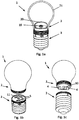
- FIG. 1 a shows the luminous element 1 in the assembled state with a lamp head 2 and a lamp base 3.
- the lamp head 2 comprises a lampshade 21, preferably made of quartz glass, in the interior of which an LED module 19 with preferably a plurality of individual LEDs is arranged.
- an LED module 19 with preferably a plurality of individual LEDs is arranged.
- a diffuser 20 is arranged around the LED module 19.
- the diffuser 20 can be matted and / or coated, preferably coated with phosphor.
- Figures 1b and 1c show the luminous element 1 in the open state, the lamp head 2 being separated from the lamp base 3.
- the plug connection for connecting the lamp head 2 to the lamp base 3 comprises closure elements 4 on the lamp head 2, which engage in recesses 5 on the lamp base 3.
- a centering pin 10 is provided on the lamp head 2 which engages in a centering opening 11 on the lamp base 3. This facilitates the precisely fitting insertion of the closure elements 4 into the recesses 5.
- Fig. 2 shows an exploded view of the luminous element 1 according to the invention, individual components of the lamp head 2 and the lamp base 3 being shown.
- a diffuser 20 which covers an LED module 19.
- the LED module 19 is arranged inside a heat sink 14 which has cooling fins on its outer circumference in order to dissipate the heat output of the LED module 19.
- the closure elements 4 and the centering pin 10 are arranged inside a cover sleeve 13 with a sleeve part and a cover plate. Furthermore, electrical terminals 23 are located inside the cover sleeve 13 for making electrical contact with the closure elements 4.
- the closure elements 4 are electrically conductive, preferably made of copper.
- a wireless radio module (not shown), in particular a WLAN module, ZigBee module or the like, can be arranged in the heat sink 14 and / or in the cover sleeve 13.
- the lamp base 3 comprises a thread 24 with a voltage converter 18 arranged therein and a coupling part 12.
- the coupling part 12 carries electrical terminals 23 for contacting the closure elements 4 when the luminous element is plugged together.
- cooling fins are provided in areas.
- a first marking 15 is located on the outer circumference of the heat sink 15 in the area of the cooling fins. Furthermore, there are second markings 16 on the outer circumference of the coupling part 12, likewise in the area of the cooling fins, and an LED 17 outside the cooling fins.
- Fig. 3a shows a view of the cover plate 22 in detail.
- the cover plate 22 is circular and has a centering opening 11 in its center.
- 2 recesses 5 Concentrically around the center point, 2 recesses 5 which are annular in sections are arranged. These each comprise an enlarged receiving section 8 and two retaining sections 9, which extend tangentially therefrom and have a reduced extent.
- the recesses 5 are arranged at an angle of 154 ° to one another, so that the connection of the lamp head 2 to the lamp base 3 is only possible in one position.
- closure element 4 shown is designed in such a way that it can be introduced into the receiving section 8 and fixed by rotating the lamp head 2.
- the closure element 4 is mushroom-shaped and has a stem 6, the diameter of which is adapted to the extent of the retaining sections 9, and a closure head 9, the diameter of which is adapted to the extent of the receiving section 8.
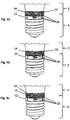
- Figures 4a-4c show different positions of the lamp head 2 in relation to the lamp base 3.
- the position shown is the luminous element 1 in a first electrical operating state.
- the first marking 15 on the heat sink 14 is aligned with that second marking 16 on the coupling part 12 which designates the first operating state.
- This means that the lamp head 2 is in a position rotated to the right with respect to the lamp base 3, and the luminous element is operated, for example, with high power or with a first color temperature.
- the luminous element 1 is not in an electrical operating state but is deactivated.
- the first marking 15 on the heat sink 14 is aligned with that second marking 16 on the coupling part 12, which indicates the open position. This means that the lamp head 2 is in a position that is central to the lamp base 3, and the lamp head can be removed from the lamp base.
Landscapes
- Engineering & Computer Science (AREA)
- General Engineering & Computer Science (AREA)
- Physics & Mathematics (AREA)
- Microelectronics & Electronic Packaging (AREA)
- Optics & Photonics (AREA)
- Non-Portable Lighting Devices Or Systems Thereof (AREA)
- Arrangement Of Elements, Cooling, Sealing, Or The Like Of Lighting Devices (AREA)
Description
- Die Erfindung betrifft einen Leuchtkörper mit einem Lampenkopf und einem damit beweglich verbundenen Lampensockel gemäß dem Oberbegriff des Anspruchs 1.
- Täglich werden weltweit Millionen Leuchtkörper in den Müll geworfen, obwohl diese teilweise noch in Ordnung sind oder zumindest eine Komponente (Netzteil, Leuchte, etc.) noch funktionell ist. Ein besonders großes Problem stellen in dieser Hinsicht Leuchtstofflampen dar, da diese toxische Stoffe beinhalten.
- Es ist deshalb aus dem Stand der Technik bekannt, Lampenkopf und Lampensockel eines Leuchtkörpers derart auszuführen, dass sie voneinander getrennt werden können. Dies hat den Vorteil, dass bei Defekt eines Teils im Lampenkopf nur dieser ausgetauscht werden muss, während der Lampensockel weiterverwendet werden kann.
- Auch sind aus dem Stand der Technik Leuchtkörper bekannt, die umschaltbare Leistungen oder Leuchtfarben aufweisen, wobei die Umschaltung in der Regel durch ein Bedienelement am Leuchtkörper erfolgt. Ein derartiges Bedienelement am Leuchtkörper ist jedoch schwierig zu bedienen und meist auch aus ästhetischen Gründen unerwünscht.
- Verschiedene Leuchtkörper sind aus der
WO 2012/168860A2 ,WO 2012/168831 A2 ,WO 2012/148384 A1 ,DE 10 2012 207188 A1 ,EP 1 348 902A1 undDE 10 2012 207190 A1 bekannt. - Die Aufgabe der vorliegenden Erfindung besteht darin, diese bekannten Leuchtkörper in ihrer Bedienbarkeit zu verbessern und weiter auszubilden, um einen ästhetisch ansprechenden Leuchtkörper zu realisieren, der dennoch die bekannte Funktionalität realisiert und wirtschaftlich in seiner Herstellung und Benutzung ist.
- Die Aufgabe wird erfindungsgemäß mit einem eingangs genannten Leuchtkörper mit den Merkmalen des Kennzeichens des Anspruchs 1 gelöst.
- Es kann insbesondere vorgesehen sein, dass Lampenkopf und Lampensockel durch eine Steckverbindung lösbar verbunden sind, wobei die Steckverbindung in einer ersten Stellung und zumindest einer zweiten Stellung fixierbar ist, wobei in der ersten Stellung ein erster elektrischer Betriebszustand hergestellt wird, und in der zumindest einen zweiten Stellung ein zweiter elektrischer Betriebszustand hergestellt wird.
- Durch die erfindungsgemäße Steckverbindung kann der Lampenkopf in zwei unterschiedlichen Stellungen am Lampensockel fixiert werden. Die beiden Stellungen unterscheiden sich in ihrem elektrischen Betriebszustand, sodass der elektrische Betriebszustand des Leuchtkörpers beim Fixieren des Lampenkopfs am Lampensockel durch den Benutzer ausgewählt werden kann. Dadurch wird erreicht, dass am Leuchtkörper kein Bedienelement vorgesehen werden muss, was sowohl die Herstellungskosten reduziert, als auch die ästhetische Erscheinung des Leuchtkörpers verbessert.
- Erfindungsgemäß ist eine dritte Stellung vorgesehen, in der der Lampenkopf nicht am Lampensockel fixiert ist, sondern auf den Lampensockel aufgesetzt und von ihm getrennt werden kann.
- Es kann vorgesehen sein, dass die Steckverbindung als vorzugsweise stirnseitig am Lampenkopf und am Lampensockel angeordneter Bajonettverschluss mit einer ersten Fixierstellung und zumindest einer zweiten Fixierstellung, sowie vorzugsweise mit einer Öffnungs-Stellung, ausgeführt ist.
- Es kann vorgesehen sein, dass der Bajonettverschluss zumindest zwei Verschlusselemente umfasst, die stirnseitig am Lampenkopf angeordnet sind und zum Eingriff in zumindest zwei abschnittsweise ringförmige, stirnseitig am Lampensockel angeordnete und zu den Verschlusselementen korrespondierende Ausnehmungen ausgeführt sind.
- Es kann vorgesehen sein, dass die Verschlusselemente pilzförmig mit einem zylinderförmigen Stamm und einem zylinderförmigen, die Ausnehmungen hintergreifenden Verschlusskopf ausgeführt sind.
- Es kann vorgesehen sein, dass die Ausnehmungen jeweils einen erweiterten Aufnahmeabschnitt zur Aufnahme der Verschlusselemente und zwei Rückhalteabschnitte aufweisen, die sich vom Aufnahmeabschnitt in Umfangsrichtung erstrecken und vorzugsweise zur Fixierung der Verschlusselemente verjüngen.
- Es kann vorgesehen sein, dass die zumindest zwei Verschlusselemente und die korrespondierenden zumindest zwei Ausnehmungen jeweils in einer Ebene winkelig zueinander angeordnet sind, wobei der Winkel ungleich 180° ist, sodass ein Einsetzen der Verschlusselemente in die Aufnahmeabschnitte nur in einer einzigen Position möglich ist. Der Winkel kann insbesondere etwa 154 "betragen.
- Es kann vorgesehen sein, dass am Lampenkopf ein Zentrierstift vorgesehen ist, der zum Eingriff in eine Zentrieröffnung am Lampensockel ausgeführt ist, um eine geführte Verbindung des Lampenkopfes mit dem Lampensockel zu ermöglichen.
- Es kann vorgesehen sein, dass die Verschlusselemente im eingerasteten Zustand des Bajonettverschlusses mit elektrischen oder elektronischen Komponenten im Lampenkopf und/oder Lampensockel in Verbindung stehen.
- Es kann vorgesehen sein, dass die Steckverbindung zumindest teilweise im Inneren eines am Lampensockel angeordneten Kupplungsteils und/oder einer Abdeckhülse angeordnet ist.
- Es kann vorgesehen sein, dass am Lampenkopf, vorzugsweise an einem Kühlkörper, zumindest eine erste Markierung sowie am Kupplungsteil zumindest eine korrespondierende zweite Markierung vorgesehen ist, um die Position der Steckverbindung und den entsprechenden Betriebszustand des Leuchtkörpers anzuzeigen.
- Es kann vorgesehen sein, dass am Kupplungsteil und/oder am Kühlkörper ein Leuchtmittel, vorzugsweise eine LED, zur Anzeige der Position der Steckverbindung und des entsprechenden Betriebszustands des Leuchtkörpers angeordnet ist.
- Es kann vorgesehen sein, dass im Lampenkopf ein Funkmodul zur Steuerung des Leuchtkörpers angeordnet ist. Dabei kann es sich insbesondere um ein WLAN- oder ZigBee-Modul handeln.
- Es kann vorgesehen sein, dass im Lampensockel ein Spannungswandler angeordnet ist.
- Es kann vorgesehen sein, dass im Inneren des Lampenkopfes ein LED-Modul vorgesehen ist, welches mit einer am LED Chip aufgebrachten Phosphor-Beschichtung versehen sein kann.
- Es kann vorgesehen sein, dass ein das LED-Modul abschirmender, beschichteter und/oder farbgebender Diffusor, insbesondere ein mit Phosphor beschichteter Diffusor, sowie ein den Diffusor umgebender, transparenter und/oder mattierter Lampenschirm vorgesehen sind.
- Es kann vorgesehen sein, dass sich der erste und zweite elektrische Betriebszustand in der durch das LED-Modul abgegebenen Lichtleistung und/oder Farbtemperatur unterscheidet.
- Weitere vorteilhafte Merkmale ergeben sich aus den Patentansprüchen, den Ausführungsbeispielen und den Zeichnungen.
- Die Erfindung wird im Folgenden an Hand eines nicht ausschließlichen Ausführungsbeispiels näher erläutert.
-
Fig. 1a-1c zeigen unterschiedliche Ansichten eines Ausführungsbeispiels eines erfindungsgemäßen Leuchtkörpers 1.Fig. 1 a zeigt den Leuchtkörper 1 im zusammengesteckten Zustand mit einem Lampenkopf 2 und einem Lampensockel 3. Der Lampenkopf 2 umfasst einen Lampenschirm 21 vorzugsweise aus Quarzglas, in dessen Innenraum ein LED-Modul 19 mit vorzugsweise einer Vielzahl einzelner LEDs angeordnet ist. Um das vom LED-Modul 19 abgestrahlte Licht zu färben und/oder zu homogenisieren, ist rund um das LED-Modul 19 ein Diffusor 20 angeordnet. Der Diffusor 20 kann mattiert und/oder beschichtet, vorzugsweise mit Phosphor beschichtet sein. -
Fig. 1b und 1c zeigen den Leuchtkörper 1 im geöffneten Zustand, wobei der Lampenkopf 2 vom Lampensockel 3 getrennt ist. Die Steckverbindung zum Verbinden des Lampenkopfes 2 mit dem Lampensockel 3 umfasst Verschlusselemente 4 am Lampenkopf 2, die in Ausnehmungen 5 am Lampensockel 3 eingreifen. Weiters ist ein am Lampenkopf 2 ein Zentrierstift 10 vorgesehen, der in eine Zentrieröffnung 11 am Lampensockel 3 eingreift. Dadurch wird das passgenaue Einsetzen der Verschlusselemente 4 in die Ausnehmungen 5 erleichtert. -
Fig. 2 zeigt eine Explosionsdarstellung des erfindungsgemäßen Leuchtkörpers 1, wobei einzelne Komponenten des Lampenkopfes 2 und des Lampensockels 3 dargestellt sind. Im Lampenschirm 21 befindet sich ein Diffusor 20, der ein LED-Modul 19 abdeckt. Das LED-Modul 19 ist im Inneren eines Kühlkörpers 14 angeordnet, der an seinem äußeren Umfang Kühlrippen aufweist, um die Wärmeleistung des LED-Moduls 19 abzuführen. - Die Verschlusselemente 4 und der Zentrierstift 10 sind im Inneren einer Abdeckhülse 13 mit Hülsenteil und Abdeckplatte angeordnet. Weiters befinden sich im Inneren der Abdeckhülse 13 elektrische Klemmen 23 zur elektrischen Kontaktierung der Verschlusselemente 4. Die Verschlusselemente 4 sind elektrisch leitfähig, vorzugsweise aus Kupfer ausgeführt. Weiters kann im Kühlkörper 14 und/oder in der Abdeckhülse 13 ein (nicht dargestelltes) drahtloses Funkmodul, insbesondere ein WLAN-Modul, ZigBee-Modul oder dergleichen, angeordnet sein.
- Der Lampensockel 3 umfasst ein Gewinde 24 mit einem darin angeordneten Spannungswandler 18 sowie einem Kupplungsteil 12. Der Kupplungsteil 12 trägt in seinem Inneren elektrische Klemmen 23 zur Kontaktierung der Verschlusselemente 4 im zusammengesteckten Zustand des Leuchtkörpers. Am äußeren Umfang des Kupplungsteils 12 sind bereichsweise Kühlrippen vorgesehen. Stirnseitig ist am Lampensockel 3 eine Abdeckplatte 22 abgeordnet, die Ausnehmungen 5 zur Aufnahme der Verschlusselemente 5 und eine Zentrieröffnung 11 zur Aufnahme des Zentrierstiftes 10 aufweist.
- Am äußeren Umfang des Kühlkörpers 15 befindet sich im Bereich der Kühlrippen eine erste Markierung 15. Weiters befinden sich am äußeren Umfang des Kupplungsteils 12, ebenfalls im Bereich der Kühlrippen, zweite Markierungen 16 sowie, außerhalb der Kühlrippen, eine LED 17.
-
Fig. 3a zeigt eine Ansicht der Abdeckplatte 22 im Detail. Die Abdeckplatte 22 ist kreisförmig und weist in ihrem Mittelpunkt eine Zentrieröffnung 11 auf. Konzentrisch um den Mittelpunkt sind 2 abschnittsweise ringförmige Ausnehmungen 5 angeordnet. Diese umfassen jeweils einen erweiterten Aufnahmeabschnitt 8 und zwei Rückhalteabschnitte 9, die sich davon tangential erstrecken und reduzierte Ausdehnung aufweisen. Es kann insbesondere vorgesehen sein, dass sich die Rückhalteabschnitte ausgehend vom Aufnahmeabschnitt 8 verjüngen, um die Rückhaltekraft der Steckverbindung zu erhöhen. Die Ausnehmungen 5 sind zueinander in einem Winkel von 154° angeordnet, sodass die Verbindung des Lampenkopfes 2 mit dem Lampensockel 3 nur in einer Position möglich ist. Das inFig. 3b dargestellte Verschlusselement 4 ist derart ausgeführt, dass es in den Aufnahmeabschnitt 8 einführbar und durch Drehen des Lampenkopfes 2 fixierbar ist. Zu diesem Zweck ist das Verschlusselement 4 pilzförmig und hat einen Stamm 6, dessen Durchmesser an die Ausdehnung der Rückhalteabschnitte 9 angepasst ist, sowie einen Verschlusskopf 9, dessen Durchmesser an die Ausdehnung des Aufnahmeabschnittes 8 angepasst ist. -
Fig. 4a - 4c zeigen verschiedene Stellungen des Lampenkopfes 2 in Bezug zum Lampensockel 3. In der inFig. 4a dargestellten Stellung befindet sich der Leuchtkörper 1 in einem ersten elektrischen Betriebszustand. Die erste Markierung 15 am Kühlkörper 14 ist mit jener zweiten Markierung 16 am Kupplungsteil 12 ausgerichtet, welche den ersten Betriebszustand bezeichnet. Dies bedeutet, dass sich der Lampenkopf 2 in einer zum Lampensockel 3 nach rechts gedrehten Position befindet, und der Leuchtkörper beispielsweise mit hoher Leistung oder mit einer ersten Farbtemperatur betrieben wird. - In der in
Fig. 4b dargestellten Stellung befindet sich der Leuchtkörper 1 in keinem elektrischen Betriebszustand, sondern ist deaktiviert. Die erste Markierung 15 am Kühlkörper 14 ist mit jener zweiten Markierung 16 am Kupplungsteil 12 ausgerichtet, welche die Öffnungsstellung andeutet. Dies bedeutet, dass sich der Lampenkopf 2 in einer zum Lampensockel 3 mittigen Position befindet, und der Lampenkopf vom Lampensockel entfernt werden kann. - In der in
Fig. 4c dargestellten Stellung befindet sich der Leuchtkörper 1 in einem zweiten elektrischen Betriebszustand. Die erste Markierung 15 am Kühlkörper 14 ist mit jener zweiten Markierung 16 am Kupplungsteil 12 ausgerichtet, welche den zweiten elektrischen Betriebszustand andeutet. Dies bedeutet, dass sich der Lampenkopf 2 in einer zum Lampensockel 3 nach links gedrehten Position befindet, und der Leuchtkörper beispielsweise mit niedriger Leistung oder mit einer zweiten Farbtemperatur betrieben wird. - Die Erfindung erstreckt sich nicht nur auf das dargestellte Ausführungsbeispiel, sondern auf sämtliche Vorrichtungen um Rahmen der nachfolgenden Patentansprüche.
-
- 1
- Leuchtkörper
- 2
- Lampenkopf
- 3
- Lampensockel
- 4
- Verschlusselement
- 5
- Ausnehmung
- 6
- Stamm
- 7
- Verschlusskopf
- 8
- Erweiterter Aufnahmeabschnitt
- 9
- Rückhalteabschnitt
- 10
- Zentrierstift
- 11
- Zentrieröffnung
- 12
- Kupplungsteil
- 13
- Abdeckhülse
- 14
- Kühlkörper
- 15
- Erste Markierung
- 16
- Zweite Markierung
- 17
- LED
- 18
- Spannungswandler
- 19
- LED-Modul
- 20
- Diffusor
- 21
- Lampenschirm
- 22
- Abdeckplatte
- 23
- Klemmen
- 24
- Gewinde
Claims (17)
- Leuchtkörper (1) umfassend einen Lampenkopf (2) und einen Lampensockel (3), wobeia. Lampenkopf (2) und Lampensockel (3) zueinander beweglich verbunden sind, wobeib. der Lampenkopf (2) relativ zum Lampensockel (3) in einer ersten Stellung und zumindest einer zweiten Stellung fixierbar ist, wobeii. in der ersten Stellung ein erster elektrischer Betriebszustand hergestellt wird, undii. in der zumindest einen zweiten Stellung ein zweiter elektrischer Betriebszustand hergestellt wird,wobei in der ersten und in der zweiten Stellung der Leuchtkörper aktiviert ist,
dadurch gekennzeichnet, dassc. eine dritte Stellung vorgesehen ist, in der der Lampenkopf (3) nicht am Lampensockel (2) fixiert ist,wobei in dieser dritten Stellung der Lampenkopf (2) auf den Lampensockel (3) aufgesetzt und von ihm getrennt werden kann, und wobei in der dritten Stellung der Leuchtkörper in keinem elektrischen Betriebszustand, also deaktiviert ist. - Leuchtkörper (1) nach Anspruch 1, dadurch gekennzeichnet, dass der Lampenkopf (2) und der Lampensockel (3) durch eine Steckverbindung lösbar verbunden sind, wobeia. die Steckverbindung in einer ersten Stellung und zumindest einer zweiten Stellung fixierbar ist, wobeii. in der ersten Stellung ein erster elektrischer Betriebszustand hergestellt wird, undii. in der zumindest einen zweiten Stellung ein zweiter elektrischer Betriebszustand hergestellt wird.
- Leuchtkörper (1) nach Anspruch 1 oder 2, dadurch gekennzeichnet, dass die Steckverbindung als Bajonettverschluss mit einer ersten Stellung und zumindest einer zweiten Stellung ausgeführt ist.
- Leuchtkörper (1) nach Anspruch 3, dadurch gekennzeichnet, dass der Bajonettverschluss zumindest zwei Verschlusselemente (4) umfasst, die stirnseitig am Lampenkopf (2) angeordnet sind und zum Eingriff in zumindest zwei abschnittsweise ringförmige, stirnseitig am Lampensockel (3) angeordnete und zu den Verschlusselementen (4) korrespondierende Ausnehmungen (5) ausgeführt sind.
- Leuchtkörper (1) nach Anspruch 4, dadurch gekennzeichnet, dass die Verschlusselemente (4) pilzförmig mit einem zylinderförmigen Stamm (6) und einem zylinderförmigen, die Ausnehmungen (5) hintergreifenden Verschlusskopf (7) ausgeführt sind.
- Leuchtkörper (1) nach Anspruch 4 oder 5, dadurch gekennzeichnet, dass die Ausnehmungen (5) jeweils einen erweiterten Aufnahmeabschnitt (8) zur Aufnahme der Verschlusselemente (4) und zwei Rückhalteabschnitte (9) aufweisen, die sich vom Aufnahmeabschnitt (8) in Umfangsrichtung erstrecken und vorzugsweise zur Fixierung der Verschlusselemente (4) verjüngen.
- Leuchtkörper (1) nach Anspruch 6, dadurch gekennzeichnet, dass die zumindest zwei Verschlusselemente (4) und die korrespondierenden zumindest zwei Ausnehmungen (5) jeweils in einer Ebene winkelig zueinander angeordnet sind, wobei der Winkel ungleich 180° ist, sodass ein Einsetzen der Verschlusselemente (4) in die Aufnahmeabschnitte (8) nur in einer einzigen Position möglich ist.
- Leuchtkörper (1) nach einem der Ansprüche 3 bis 7, dadurch gekennzeichnet, dass am Lampenkopf (2) ein Zentrierstift (10) vorgesehen ist, der zum Eingriff in eine Zentrieröffnung (11) des Lampensockels (3) ausgeführt ist, um eine geführte Verbindung des Lampenkopfes (2) mit dem Lampensockel (3) zu ermöglichen.
- Leuchtkörper (1) nach einem der Ansprüche 3 bis 8, dadurch gekennzeichnet, dass die Verschlusselemente (4) im eingerasteten Zustand des Bajonettverschlusses mit elektrischen oder elektronischen Komponenten im Lampenkopf (2) und/oder Lampensockel (3) in Verbindung stehen.
- Leuchtkörper (1) nach einem der Ansprüche 1 bis 9, dadurch gekennzeichnet, dass die Steckverbindung zumindest teilweise im Inneren eines am Lampensockel (3) angeordneten Kupplungsteils (12) und/oder einer Abdeckhülse (13) angeordnet ist.
- Leuchtkörper (1) nach Anspruch 10, dadurch gekennzeichnet, dass am Lampenkopf (2), vorzugsweise an einem Kühlkörper (14), zumindest eine erste Markierung (15) sowie am Kupplungsteil (12) zumindest eine korrespondierende zweite Markierung (16) vorgesehen ist, um die Position der Steckverbindung und den entsprechenden Betriebszustand des Leuchtkörpers (1) anzuzeigen.
- Leuchtkörper (1) nach Anspruch 11, dadurch gekennzeichnet, dass am Kupplungsteil (9) und/oder am Kühlkörper (14) ein Leuchtmittel, vorzugsweise eine LED (17), zur Anzeige der Position der Steckverbindung und des entsprechenden Betriebszustands des Leuchtkörpers (1) angeordnet ist.
- Leuchtkörper (1) nach einem der Ansprüche 1 bis 12, dadurch gekennzeichnet, dass im Lampenkopf (2) ein Funkmodul zur Steuerung des Leuchtkörpers (1) angeordnet ist.
- Leuchtkörper (1) nach einem der Ansprüche 1 bis 13, dadurch gekennzeichnet, dass im Lampensockel (3) ein Spannungswandler (18) angeordnet ist.
- Leuchtkörper (1) nach einem der Ansprüche 1 bis 13, dadurch gekennzeichnet, dass im Inneren des Lampenkopfes (2) ein LED-Modul (19) vorgesehen ist.
- Leuchtkörper (1) nach Anspruch 15, dadurch gekennzeichnet, dass ein das LED-Modul (19) abschirmender, beschichteter und farbgebender Diffusor (20) sowie ein den Diffusor (20) umgebender, transparenter oder mattierter Lampenschirm (21) vorgesehen sind.
- Leuchtkörper nach einem der Ansprüche 1 bis 16, dadurch gekennzeichnet, dass sich der erste und zweite elektrische Betriebszustand in der durch das LED-Modul (19) abgegebenen Lichtleistung und/oder Farbtemperatur unterscheidet.
Priority Applications (2)
| Application Number | Priority Date | Filing Date | Title |
|---|---|---|---|
| ATA50252/2015A AT516979B1 (de) | 2015-03-30 | 2015-03-30 | Leuchtkörper |
| EP16020102.6A EP3141813B1 (de) | 2015-03-30 | 2016-03-29 | Leuchtkörper als modulares, konfigurierbares, steuerbares led-leuchtmittel |
Applications Claiming Priority (2)
| Application Number | Priority Date | Filing Date | Title |
|---|---|---|---|
| ATA50252/2015A AT516979B1 (de) | 2015-03-30 | 2015-03-30 | Leuchtkörper |
| EP16020102.6A EP3141813B1 (de) | 2015-03-30 | 2016-03-29 | Leuchtkörper als modulares, konfigurierbares, steuerbares led-leuchtmittel |
Publications (2)
| Publication Number | Publication Date |
|---|---|
| EP3141813A1 EP3141813A1 (de) | 2017-03-15 |
| EP3141813B1 true EP3141813B1 (de) | 2021-01-27 |
Family
ID=74044789
Family Applications (1)
| Application Number | Title | Priority Date | Filing Date |
|---|---|---|---|
| EP16020102.6A Not-in-force EP3141813B1 (de) | 2015-03-30 | 2016-03-29 | Leuchtkörper als modulares, konfigurierbares, steuerbares led-leuchtmittel |
Country Status (2)
| Country | Link |
|---|---|
| EP (1) | EP3141813B1 (de) |
| AT (1) | AT516979B1 (de) |
Families Citing this family (1)
| Publication number | Priority date | Publication date | Assignee | Title |
|---|---|---|---|---|
| EP4100677A1 (de) * | 2020-02-07 | 2022-12-14 | Ansorg GmbH | Leuchtmittelsystem |
Family Cites Families (10)
| Publication number | Priority date | Publication date | Assignee | Title |
|---|---|---|---|---|
| DE19714874C1 (de) * | 1997-04-10 | 1998-07-09 | Broekelmann Jaeger & Busse | Fassung für elektrotechnische Bauelemente |
| EP1348902A1 (de) * | 2002-03-26 | 2003-10-01 | Koninklijke Philips Electronics N.V. | Lampe und Lampenfassung mit peripheren Verriegelungselemente |
| DE102008028538A1 (de) * | 2008-06-16 | 2009-12-17 | Osram Gesellschaft mit beschränkter Haftung | Beleuchtungssystem |
| DE102008055864A1 (de) * | 2008-11-05 | 2010-05-06 | Zumtobel Lighting Gmbh | LED-Leuchte |
| DE102010014474B4 (de) * | 2010-04-09 | 2013-01-10 | Bjb Gmbh & Co. Kg | Fassung |
| WO2012148384A1 (en) * | 2011-04-26 | 2012-11-01 | The Procter & Gamble Company | Stemmed lighting assembly with disk-shaped illumination element |
| AT12763U1 (de) * | 2011-04-29 | 2012-11-15 | Tridonic Gmbh & Co Kg | Led leuchtmittel |
| DE102012207188A1 (de) * | 2011-04-29 | 2012-10-31 | Tridonic Gmbh & Co. Kg | LED Leuchtmittel |
| JP6010116B2 (ja) * | 2011-06-06 | 2016-10-19 | フィリップス ライティング ホールディング ビー ヴィ | ソケット、照明モジュール、及び、照明器具 |
| US9285107B2 (en) * | 2011-06-10 | 2016-03-15 | Koninklijke Philips N.V. | Retrofit lighting device |
-
2015
- 2015-03-30 AT ATA50252/2015A patent/AT516979B1/de not_active IP Right Cessation
-
2016
- 2016-03-29 EP EP16020102.6A patent/EP3141813B1/de not_active Not-in-force
Non-Patent Citations (1)
| Title |
|---|
| None * |
Also Published As
| Publication number | Publication date |
|---|---|
| EP3141813A1 (de) | 2017-03-15 |
| AT516979A1 (de) | 2016-10-15 |
| AT516979B1 (de) | 2017-03-15 |
Similar Documents
| Publication | Publication Date | Title |
|---|---|---|
| EP1989724B1 (de) | Lampensockel und lampe mit einem lampensockel | |
| DE202010002676U1 (de) | Einbauleuchte mit Basiskörper und domförmigem Reflektor | |
| DE2622424A1 (de) | Beleuchtungsvorrichtung | |
| EP1150154A1 (de) | Anordnung und Verfahren zur ringförmigen Beleuchtung, insbesondere zur Auflichtbeleuchtung bei Mikroskopen | |
| DE202011050024U1 (de) | Beleuchtungslampe | |
| DE10212895A1 (de) | Signalsäule | |
| DE102009023268A1 (de) | LED-Beleuchtungseinheit mit Reflektor | |
| EP0913625A2 (de) | Signalleuchte | |
| AT14620U1 (de) | Leuchte mit Trägerelement und lösbar befestigbarem Leuchtmodul | |
| EP2539632B1 (de) | Kühlkörper für eine lichtquelle | |
| EP3141813B1 (de) | Leuchtkörper als modulares, konfigurierbares, steuerbares led-leuchtmittel | |
| DE102009017162B4 (de) | Modulsystem zur Schaffung einer Leuchte | |
| DE102007009229A1 (de) | Lichtquelle zur Simulation einer Punktlichtquelle, sowie Leuchte mit einer derartigen Lichtquelle | |
| EP2851612B1 (de) | Leuchte mit Lampenschirm | |
| EP3686480B1 (de) | Anordnung zur lichtabgabe mit veränderbarer lichtabstrahlcharakteristik | |
| DE202018100238U1 (de) | Modular erweiterbare und formveränderliche Leuchte | |
| DE202014004861U1 (de) | Lampe und Adapter für eine Lampe | |
| DE102008055694A1 (de) | Stellrad | |
| DE10201131A1 (de) | Leuchtkörper | |
| EP1467141B1 (de) | Leuchte mit geschlossener Lichtabstrahlfläche | |
| DE102018101503A1 (de) | Elektrische Steckverbindung zum Verbinden eines Leuchtmittels mit einer elektrischen Anschlussleitung | |
| DE102012218785A1 (de) | Lampe | |
| DE60315608T2 (de) | Schnellverschluss-Lampenfassung in T-Ausführung | |
| DE4438489C2 (de) | Signalleuchte, insbsondere Baustellenleuchte oder Bakenleuchte | |
| DE19859730B4 (de) | Leuchte mit aufschraubbaren Adapterring |
Legal Events
| Date | Code | Title | Description |
|---|---|---|---|
| PUAI | Public reference made under article 153(3) epc to a published international application that has entered the european phase |
Free format text: ORIGINAL CODE: 0009012 |
|
| STAA | Information on the status of an ep patent application or granted ep patent |
Free format text: STATUS: THE APPLICATION HAS BEEN PUBLISHED |
|
| AK | Designated contracting states |
Kind code of ref document: A1 Designated state(s): AL AT BE BG CH CY CZ DE DK EE ES FI FR GB GR HR HU IE IS IT LI LT LU LV MC MK MT NL NO PL PT RO RS SE SI SK SM TR |
|
| AX | Request for extension of the european patent |
Extension state: BA ME |
|
| STAA | Information on the status of an ep patent application or granted ep patent |
Free format text: STATUS: REQUEST FOR EXAMINATION WAS MADE |
|
| 17P | Request for examination filed |
Effective date: 20171220 |
|
| RBV | Designated contracting states (corrected) |
Designated state(s): AL AT BE BG CH CY CZ DE DK EE ES FI FR GB GR HR HU IE IS IT LI LT LU LV MC MK MT NL NO PL PT RO RS SE SI SK SM TR |
|
| STAA | Information on the status of an ep patent application or granted ep patent |
Free format text: STATUS: EXAMINATION IS IN PROGRESS |
|
| 17Q | First examination report despatched |
Effective date: 20190702 |
|
| RIC1 | Information provided on ipc code assigned before grant |
Ipc: F21K 9/232 20160101ALI20200723BHEP Ipc: F21V 17/00 20060101ALI20200723BHEP Ipc: F21K 9/65 20160101ALI20200723BHEP Ipc: F21Y 115/15 20160101ALN20200723BHEP Ipc: H01R 33/945 20060101ALN20200723BHEP Ipc: H05B 33/08 20200101ALI20200723BHEP Ipc: F21V 19/04 20060101AFI20200723BHEP Ipc: F21V 19/02 20060101ALI20200723BHEP |
|
| GRAP | Despatch of communication of intention to grant a patent |
Free format text: ORIGINAL CODE: EPIDOSNIGR1 |
|
| STAA | Information on the status of an ep patent application or granted ep patent |
Free format text: STATUS: GRANT OF PATENT IS INTENDED |
|
| RIC1 | Information provided on ipc code assigned before grant |
Ipc: F21V 19/04 20060101AFI20200724BHEP Ipc: F21Y 115/15 20160101ALN20200724BHEP Ipc: F21K 9/232 20160101ALI20200724BHEP Ipc: F21K 9/65 20160101ALI20200724BHEP Ipc: F21V 17/00 20060101ALI20200724BHEP Ipc: H01R 33/945 20060101ALN20200724BHEP Ipc: F21V 19/02 20060101ALI20200724BHEP Ipc: H05B 33/08 20200101ALI20200724BHEP |
|
| INTG | Intention to grant announced |
Effective date: 20200902 |
|
| GRAS | Grant fee paid |
Free format text: ORIGINAL CODE: EPIDOSNIGR3 |
|
| GRAA | (expected) grant |
Free format text: ORIGINAL CODE: 0009210 |
|
| STAA | Information on the status of an ep patent application or granted ep patent |
Free format text: STATUS: THE PATENT HAS BEEN GRANTED |
|
| AK | Designated contracting states |
Kind code of ref document: B1 Designated state(s): AL AT BE BG CH CY CZ DE DK EE ES FI FR GB GR HR HU IE IS IT LI LT LU LV MC MK MT NL NO PL PT RO RS SE SI SK SM TR |
|
| REG | Reference to a national code |
Ref country code: GB Ref legal event code: FG4D Free format text: NOT ENGLISH |
|
| REG | Reference to a national code |
Ref country code: CH Ref legal event code: EP |
|
| REG | Reference to a national code |
Ref country code: AT Ref legal event code: REF Ref document number: 1358671 Country of ref document: AT Kind code of ref document: T Effective date: 20210215 |
|
| REG | Reference to a national code |
Ref country code: IE Ref legal event code: FG4D Free format text: LANGUAGE OF EP DOCUMENT: GERMAN |
|
| REG | Reference to a national code |
Ref country code: DE Ref legal event code: R096 Ref document number: 502016012285 Country of ref document: DE |
|
| REG | Reference to a national code |
Ref country code: NL Ref legal event code: MP Effective date: 20210127 |
|
| REG | Reference to a national code |
Ref country code: LT Ref legal event code: MG9D |
|
| PG25 | Lapsed in a contracting state [announced via postgrant information from national office to epo] |
Ref country code: PT Free format text: LAPSE BECAUSE OF FAILURE TO SUBMIT A TRANSLATION OF THE DESCRIPTION OR TO PAY THE FEE WITHIN THE PRESCRIBED TIME-LIMIT Effective date: 20210527 Ref country code: NO Free format text: LAPSE BECAUSE OF FAILURE TO SUBMIT A TRANSLATION OF THE DESCRIPTION OR TO PAY THE FEE WITHIN THE PRESCRIBED TIME-LIMIT Effective date: 20210427 Ref country code: NL Free format text: LAPSE BECAUSE OF FAILURE TO SUBMIT A TRANSLATION OF THE DESCRIPTION OR TO PAY THE FEE WITHIN THE PRESCRIBED TIME-LIMIT Effective date: 20210127 Ref country code: BG Free format text: LAPSE BECAUSE OF FAILURE TO SUBMIT A TRANSLATION OF THE DESCRIPTION OR TO PAY THE FEE WITHIN THE PRESCRIBED TIME-LIMIT Effective date: 20210427 Ref country code: GR Free format text: LAPSE BECAUSE OF FAILURE TO SUBMIT A TRANSLATION OF THE DESCRIPTION OR TO PAY THE FEE WITHIN THE PRESCRIBED TIME-LIMIT Effective date: 20210428 Ref country code: FI Free format text: LAPSE BECAUSE OF FAILURE TO SUBMIT A TRANSLATION OF THE DESCRIPTION OR TO PAY THE FEE WITHIN THE PRESCRIBED TIME-LIMIT Effective date: 20210127 Ref country code: HR Free format text: LAPSE BECAUSE OF FAILURE TO SUBMIT A TRANSLATION OF THE DESCRIPTION OR TO PAY THE FEE WITHIN THE PRESCRIBED TIME-LIMIT Effective date: 20210127 Ref country code: LT Free format text: LAPSE BECAUSE OF FAILURE TO SUBMIT A TRANSLATION OF THE DESCRIPTION OR TO PAY THE FEE WITHIN THE PRESCRIBED TIME-LIMIT Effective date: 20210127 |
|
| PG25 | Lapsed in a contracting state [announced via postgrant information from national office to epo] |
Ref country code: LV Free format text: LAPSE BECAUSE OF FAILURE TO SUBMIT A TRANSLATION OF THE DESCRIPTION OR TO PAY THE FEE WITHIN THE PRESCRIBED TIME-LIMIT Effective date: 20210127 Ref country code: PL Free format text: LAPSE BECAUSE OF FAILURE TO SUBMIT A TRANSLATION OF THE DESCRIPTION OR TO PAY THE FEE WITHIN THE PRESCRIBED TIME-LIMIT Effective date: 20210127 Ref country code: RS Free format text: LAPSE BECAUSE OF FAILURE TO SUBMIT A TRANSLATION OF THE DESCRIPTION OR TO PAY THE FEE WITHIN THE PRESCRIBED TIME-LIMIT Effective date: 20210127 Ref country code: SE Free format text: LAPSE BECAUSE OF FAILURE TO SUBMIT A TRANSLATION OF THE DESCRIPTION OR TO PAY THE FEE WITHIN THE PRESCRIBED TIME-LIMIT Effective date: 20210127 |
|
| PG25 | Lapsed in a contracting state [announced via postgrant information from national office to epo] |
Ref country code: IS Free format text: LAPSE BECAUSE OF FAILURE TO SUBMIT A TRANSLATION OF THE DESCRIPTION OR TO PAY THE FEE WITHIN THE PRESCRIBED TIME-LIMIT Effective date: 20210527 |
|
| REG | Reference to a national code |
Ref country code: DE Ref legal event code: R119 Ref document number: 502016012285 Country of ref document: DE |
|
| PG25 | Lapsed in a contracting state [announced via postgrant information from national office to epo] |
Ref country code: EE Free format text: LAPSE BECAUSE OF FAILURE TO SUBMIT A TRANSLATION OF THE DESCRIPTION OR TO PAY THE FEE WITHIN THE PRESCRIBED TIME-LIMIT Effective date: 20210127 Ref country code: CZ Free format text: LAPSE BECAUSE OF FAILURE TO SUBMIT A TRANSLATION OF THE DESCRIPTION OR TO PAY THE FEE WITHIN THE PRESCRIBED TIME-LIMIT Effective date: 20210127 Ref country code: MC Free format text: LAPSE BECAUSE OF FAILURE TO SUBMIT A TRANSLATION OF THE DESCRIPTION OR TO PAY THE FEE WITHIN THE PRESCRIBED TIME-LIMIT Effective date: 20210127 Ref country code: SM Free format text: LAPSE BECAUSE OF FAILURE TO SUBMIT A TRANSLATION OF THE DESCRIPTION OR TO PAY THE FEE WITHIN THE PRESCRIBED TIME-LIMIT Effective date: 20210127 |
|
| REG | Reference to a national code |
Ref country code: CH Ref legal event code: PL |
|
| PG25 | Lapsed in a contracting state [announced via postgrant information from national office to epo] |
Ref country code: SK Free format text: LAPSE BECAUSE OF FAILURE TO SUBMIT A TRANSLATION OF THE DESCRIPTION OR TO PAY THE FEE WITHIN THE PRESCRIBED TIME-LIMIT Effective date: 20210127 Ref country code: RO Free format text: LAPSE BECAUSE OF FAILURE TO SUBMIT A TRANSLATION OF THE DESCRIPTION OR TO PAY THE FEE WITHIN THE PRESCRIBED TIME-LIMIT Effective date: 20210127 Ref country code: ES Free format text: LAPSE BECAUSE OF FAILURE TO SUBMIT A TRANSLATION OF THE DESCRIPTION OR TO PAY THE FEE WITHIN THE PRESCRIBED TIME-LIMIT Effective date: 20210127 Ref country code: DK Free format text: LAPSE BECAUSE OF FAILURE TO SUBMIT A TRANSLATION OF THE DESCRIPTION OR TO PAY THE FEE WITHIN THE PRESCRIBED TIME-LIMIT Effective date: 20210127 |
|
| PLBE | No opposition filed within time limit |
Free format text: ORIGINAL CODE: 0009261 |
|
| STAA | Information on the status of an ep patent application or granted ep patent |
Free format text: STATUS: NO OPPOSITION FILED WITHIN TIME LIMIT |
|
| REG | Reference to a national code |
Ref country code: BE Ref legal event code: MM Effective date: 20210331 |
|
| GBPC | Gb: european patent ceased through non-payment of renewal fee |
Effective date: 20210427 |
|
| 26N | No opposition filed |
Effective date: 20211028 |
|
| PG25 | Lapsed in a contracting state [announced via postgrant information from national office to epo] |
Ref country code: DE Free format text: LAPSE BECAUSE OF NON-PAYMENT OF DUE FEES Effective date: 20211001 Ref country code: GB Free format text: LAPSE BECAUSE OF NON-PAYMENT OF DUE FEES Effective date: 20210427 Ref country code: FR Free format text: LAPSE BECAUSE OF NON-PAYMENT OF DUE FEES Effective date: 20210331 Ref country code: IE Free format text: LAPSE BECAUSE OF NON-PAYMENT OF DUE FEES Effective date: 20210329 Ref country code: AL Free format text: LAPSE BECAUSE OF FAILURE TO SUBMIT A TRANSLATION OF THE DESCRIPTION OR TO PAY THE FEE WITHIN THE PRESCRIBED TIME-LIMIT Effective date: 20210127 Ref country code: CH Free format text: LAPSE BECAUSE OF NON-PAYMENT OF DUE FEES Effective date: 20210331 Ref country code: LI Free format text: LAPSE BECAUSE OF NON-PAYMENT OF DUE FEES Effective date: 20210331 Ref country code: LU Free format text: LAPSE BECAUSE OF NON-PAYMENT OF DUE FEES Effective date: 20210329 |
|
| PG25 | Lapsed in a contracting state [announced via postgrant information from national office to epo] |
Ref country code: SI Free format text: LAPSE BECAUSE OF FAILURE TO SUBMIT A TRANSLATION OF THE DESCRIPTION OR TO PAY THE FEE WITHIN THE PRESCRIBED TIME-LIMIT Effective date: 20210127 |
|
| PG25 | Lapsed in a contracting state [announced via postgrant information from national office to epo] |
Ref country code: IT Free format text: LAPSE BECAUSE OF FAILURE TO SUBMIT A TRANSLATION OF THE DESCRIPTION OR TO PAY THE FEE WITHIN THE PRESCRIBED TIME-LIMIT Effective date: 20210127 |
|
| REG | Reference to a national code |
Ref country code: AT Ref legal event code: MM01 Ref document number: 1358671 Country of ref document: AT Kind code of ref document: T Effective date: 20210329 |
|
| PG25 | Lapsed in a contracting state [announced via postgrant information from national office to epo] |
Ref country code: IS Free format text: LAPSE BECAUSE OF FAILURE TO SUBMIT A TRANSLATION OF THE DESCRIPTION OR TO PAY THE FEE WITHIN THE PRESCRIBED TIME-LIMIT Effective date: 20210527 |
|
| PG25 | Lapsed in a contracting state [announced via postgrant information from national office to epo] |
Ref country code: BE Free format text: LAPSE BECAUSE OF NON-PAYMENT OF DUE FEES Effective date: 20210331 |
|
| PG25 | Lapsed in a contracting state [announced via postgrant information from national office to epo] |
Ref country code: AT Free format text: LAPSE BECAUSE OF NON-PAYMENT OF DUE FEES Effective date: 20210329 |
|
| PG25 | Lapsed in a contracting state [announced via postgrant information from national office to epo] |
Ref country code: HU Free format text: LAPSE BECAUSE OF FAILURE TO SUBMIT A TRANSLATION OF THE DESCRIPTION OR TO PAY THE FEE WITHIN THE PRESCRIBED TIME-LIMIT; INVALID AB INITIO Effective date: 20160329 |
|
| PG25 | Lapsed in a contracting state [announced via postgrant information from national office to epo] |
Ref country code: CY Free format text: LAPSE BECAUSE OF FAILURE TO SUBMIT A TRANSLATION OF THE DESCRIPTION OR TO PAY THE FEE WITHIN THE PRESCRIBED TIME-LIMIT Effective date: 20210127 |
|
| PG25 | Lapsed in a contracting state [announced via postgrant information from national office to epo] |
Ref country code: MK Free format text: LAPSE BECAUSE OF FAILURE TO SUBMIT A TRANSLATION OF THE DESCRIPTION OR TO PAY THE FEE WITHIN THE PRESCRIBED TIME-LIMIT Effective date: 20210127 |
|
| PG25 | Lapsed in a contracting state [announced via postgrant information from national office to epo] |
Ref country code: TR Free format text: LAPSE BECAUSE OF FAILURE TO SUBMIT A TRANSLATION OF THE DESCRIPTION OR TO PAY THE FEE WITHIN THE PRESCRIBED TIME-LIMIT Effective date: 20210127 |
|
| PG25 | Lapsed in a contracting state [announced via postgrant information from national office to epo] |
Ref country code: MT Free format text: LAPSE BECAUSE OF FAILURE TO SUBMIT A TRANSLATION OF THE DESCRIPTION OR TO PAY THE FEE WITHIN THE PRESCRIBED TIME-LIMIT Effective date: 20210127 |