EP3141838A1 - Abstandskamm und wärmetauscher mit besagtem abstandskamm und verfahren zur herstellung von besagtem abstandskamm - Google Patents
Abstandskamm und wärmetauscher mit besagtem abstandskamm und verfahren zur herstellung von besagtem abstandskamm Download PDFInfo
- Publication number
- EP3141838A1 EP3141838A1 EP16187754.3A EP16187754A EP3141838A1 EP 3141838 A1 EP3141838 A1 EP 3141838A1 EP 16187754 A EP16187754 A EP 16187754A EP 3141838 A1 EP3141838 A1 EP 3141838A1
- Authority
- EP
- European Patent Office
- Prior art keywords
- base
- longitudinal axis
- tabs
- heat exchanger
- spacing comb
- Prior art date
- Legal status (The legal status is an assumption and is not a legal conclusion. Google has not performed a legal analysis and makes no representation as to the accuracy of the status listed.)
- Granted
Links
Images


Classifications
-
- F—MECHANICAL ENGINEERING; LIGHTING; HEATING; WEAPONS; BLASTING
- F24—HEATING; RANGES; VENTILATING
- F24H—FLUID HEATERS, e.g. WATER OR AIR HEATERS, HAVING HEAT-GENERATING MEANS, e.g. HEAT PUMPS, IN GENERAL
- F24H1/00—Water heaters, e.g. boilers, continuous-flow heaters or water-storage heaters
- F24H1/22—Water heaters other than continuous-flow or water-storage heaters, e.g. water heaters for central heating
- F24H1/40—Water heaters other than continuous-flow or water-storage heaters, e.g. water heaters for central heating with water tube or tubes
- F24H1/43—Water heaters other than continuous-flow or water-storage heaters, e.g. water heaters for central heating with water tube or tubes helically or spirally coiled
-
- F—MECHANICAL ENGINEERING; LIGHTING; HEATING; WEAPONS; BLASTING
- F24—HEATING; RANGES; VENTILATING
- F24H—FLUID HEATERS, e.g. WATER OR AIR HEATERS, HAVING HEAT-GENERATING MEANS, e.g. HEAT PUMPS, IN GENERAL
- F24H9/00—Details
- F24H9/0005—Details for water heaters
- F24H9/001—Guiding means
- F24H9/0026—Guiding means in combustion gas channels
-
- F—MECHANICAL ENGINEERING; LIGHTING; HEATING; WEAPONS; BLASTING
- F28—HEAT EXCHANGE IN GENERAL
- F28F—DETAILS OF HEAT-EXCHANGE AND HEAT-TRANSFER APPARATUS, OF GENERAL APPLICATION
- F28F9/00—Casings; Header boxes; Auxiliary supports for elements; Auxiliary members within casings
- F28F9/007—Auxiliary supports for elements
- F28F9/013—Auxiliary supports for elements for tubes or tube-assemblies
- F28F9/0132—Auxiliary supports for elements for tubes or tube-assemblies formed by slats, tie-rods, articulated or expandable rods
-
- F—MECHANICAL ENGINEERING; LIGHTING; HEATING; WEAPONS; BLASTING
- F28—HEAT EXCHANGE IN GENERAL
- F28D—HEAT-EXCHANGE APPARATUS, NOT PROVIDED FOR IN ANOTHER SUBCLASS, IN WHICH THE HEAT-EXCHANGE MEDIA DO NOT COME INTO DIRECT CONTACT
- F28D7/00—Heat-exchange apparatus having stationary tubular conduit assemblies for both heat-exchange media, the media being in contact with different sides of a conduit wall
- F28D7/02—Heat-exchange apparatus having stationary tubular conduit assemblies for both heat-exchange media, the media being in contact with different sides of a conduit wall the conduits being helically coiled
- F28D7/024—Heat-exchange apparatus having stationary tubular conduit assemblies for both heat-exchange media, the media being in contact with different sides of a conduit wall the conduits being helically coiled the conduits of only one medium being helically coiled tubes, the coils having a cylindrical configuration
-
- F—MECHANICAL ENGINEERING; LIGHTING; HEATING; WEAPONS; BLASTING
- F28—HEAT EXCHANGE IN GENERAL
- F28F—DETAILS OF HEAT-EXCHANGE AND HEAT-TRANSFER APPARATUS, OF GENERAL APPLICATION
- F28F1/00—Tubular elements; Assemblies of tubular elements
- F28F1/10—Tubular elements and assemblies thereof with means for increasing heat-transfer area, e.g. with fins, with projections, with recesses
- F28F1/12—Tubular elements and assemblies thereof with means for increasing heat-transfer area, e.g. with fins, with projections, with recesses the means being only outside the tubular element
- F28F1/14—Tubular elements and assemblies thereof with means for increasing heat-transfer area, e.g. with fins, with projections, with recesses the means being only outside the tubular element and extending longitudinally
- F28F1/16—Tubular elements and assemblies thereof with means for increasing heat-transfer area, e.g. with fins, with projections, with recesses the means being only outside the tubular element and extending longitudinally the means being integral with the element, e.g. formed by extrusion
-
- F—MECHANICAL ENGINEERING; LIGHTING; HEATING; WEAPONS; BLASTING
- F28—HEAT EXCHANGE IN GENERAL
- F28F—DETAILS OF HEAT-EXCHANGE AND HEAT-TRANSFER APPARATUS, OF GENERAL APPLICATION
- F28F2240/00—Spacing means
Definitions
- the present invention relates to a spacing comb for a heat exchanger.
- the present invention relates to a spacing comb used to space the coils of a tubular member of a heat exchanger of a water heater or domestic boiler.
- a very commonly found heat exchanger for heating water in water heaters or domestic boilers comprises a casing; and a tubular member wound in a helix around a given axis so as to form a plurality of adjacent coils housed inside the casing.
- a liquid, generally water, passes through the helically wound tubular member, while combustion fumes, or, more generically, hot gases, containing water vapour flow through the casing, releasing most of the heat to the liquid and condensing the water vapour.
- the coils are spaced apart from each other so as to form gaps for the path of the combustion fumes.
- the heat exchanger of the type identified above is configured to define a path for the hot gases that extends between adjacent coils so as to optimize the heat exchange between the hot gases and the liquid.
- the dimensions of the tubular member, the shape of the cross section of the tubular member, and the size of the gap between adjacent coils are very important design parameters in order to optimize the heat exchange. Examples of spacing combs used for spacing the coils of heat exchangers are shown in the documents EP 1,627,190 B1 , and GB 914,083 .
- the purpose of the present invention is to provide a spacing comb that is easy to make and at the same time is capable of satisfying the heat exchanger's design parameters.
- a spacing comb for a heat exchanger is achieved in accordance with the present invention, wherein the heat exchanger comprises a tubular member which is configured to convey water to be heated, and is wound in a helix about a given axis in order to form a plurality of adjacent coils and housed in the casing; the spacing comb being configured so as to keep the adjacent coils a given distance apart and being made from a metal sheet blank which extends along a longitudinal axis and comprises a base; a plurality of tabs, which are placed partially side by side along the longitudinal axis and are configured for being bent at right angles with respect to the base so as to define a plurality of spacers supported by the base.
- the spacing comb in accordance with the present invention enables it to be made starting from a blank sheet of the tabs, i.e. of the spacers, each having a length greater than the pitch of the tabs themselves.
- the tabs are V-shaped and are inserted one into the other, partly, along the longitudinal axis.
- the particular V-shape configuration makes it possible to give the tabs a particular solidity and to make tabs having a length greater than the pitch of the tabs.
- the tabs are bent about bend lines perpendicular to the longitudinal axis.
- the bending lines are distributed along the longitudinal axis with a constant pitch.
- the spacing comb comprises two end wings, which are bent with respect to the base around further bending lines parallel to the longitudinal axis and extending from opposite sides of the tabs with respect to the base.
- the end wings give the spacing comb greater stiffness along the longitudinal axis A1.
- the wings also have a fluid dynamic function.
- a further purpose of the present invention is to provide a heat exchanger.
- a heat exchanger for a water heater or domestic boiler comprising a casing and a tubular member, which is configured to convey the water, and is wound in a helix around a given axis to form a plurality of adjacent coils and is housed within the casing; and at least two spacing combs with at least one of the salient characteristics identified above.
- the helically wound tubular member defines a cylindrical compartment inside the casing into which hot gases are admitted and an annular compartment from which the gases are evacuated.
- a further purpose of the present invention is to provide a method for making a spacing comb.
- a method for making a spacing comb comprising the steps of:
- the method according to the present invention makes it possible to provide tabs having a length greater than the pitch of the tabs.
- the method also provides for bending the tabs about folding lines perpendicular to the longitudinal axis and distributed uniformly along the longitudinal axis.
- the method also provides for the step of bending two end wings with respect to the base about further folding lines parallel to the longitudinal axis so that the end wings extend on the opposite sides of the tabs with respect to the base.
- the heat exchanger 1 denotes in its entirety a heat exchanger, which in this case is a condensing heat exchanger for heating water in a water heater or a domestic boiler.
- the heat exchanger 1 comprises a casing 2 of cylindrical shape; and a tubular member 3, which is wound, partly, in a helix around an axis A to form the coils 4.
- the tubular member 3 is made from aluminium or an aluminium based alloy, extruded and then wound in a helix.
- the casing 2 comprises a side wall 5 of substantially cylindrical shape and preferably made from a metallic material such as aluminium, or a plastic material; an end wall 6 being substantially disc-shaped and an end wall 7 having a substantially annular shape.
- the end walls 6 and 7 are attached to the side wall 5 so as to form the casing 2 and a combustion fumes flow chamber.
- the end wall 7 has a central aperture 8 and is configured to support a cylindrically-shaped burner, not shown in the attached Figures, which is arranged, partly, within the combustion fumes flow chamber.
- the hot fumes are conveyed through the central aperture 8.
- the side wall 5 comprises an aperture 9 through which combustion fumes are extracted and an aperture, not shown, for extracting the condensate.
- the helically wound tubular member 3 defines a cylindrical compartment inside the casing 2 into which hot gases are admitted and an annular compartment from which gases are evacuated.
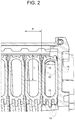
- the heat exchanger 1 further comprises two spacing combs 10 each of which has a plurality of tabs 11 arranged between the coils 4 and which function as spacers to precisely define the interstices, as better illustrated in Figure 2 .
- the cross-section of the tubular member 3 is very flattened and has two walls 12 facing each other with a very large radius of curvature and two walls 13 facing each other with a much smaller radius of curvature than the radius of curvature of the walls 12 and which are much shorter than the walls 12.
- the tubular member 3 also has wings 14 along the walls 13. Accordingly, the cross-section as a whole has much larger dimensions in the radial direction with respect to the axis A ( Figure 1 ) than in its axial dimensions with respect to the axis A ( Figure 1 ).
- the spacing of the coils 4 is very small. In the light of these design parameters of the heat exchanger 1, the length L of the tabs 11 is significantly greater than the pitch P of the tabs 11.
- the spacing comb 10 extends along a longitudinal axis A1, and comprises a base 15 for supporting the plurality of tabs 11 and two wings 16.
- Each tab 11 forms a right angle with respect to the base 15 corresponding with a respective bending line 17 perpendicular to the longitudinal axis A1.
- each tab is V-shaped and is attached to the base 15 corresponding with two section of the folding line 17, while the apex of the V defines the free end.
- Each end wing 16 forms an angle with the base 15 corresponding with a respective folding line 18 parallel to the longitudinal axis A1.
- the end wings 16 have the function of stiffening the spacing comb 10 and, at the same time, the function of slowing down the flow of the gases in the circumferential direction along the tubular compartment.
- the distance between the free end of the end wing 16 and the cylindrical part defines the section in which the gases travel in a circumferential direction.
- the free ends of the end wings 16 have an indented profile.
- the spacing comb 10 is obtained by shearing and bending a metal sheet 19 as better shown in Figure 6 .
- the method involves selecting a sheet 19 with a thickness equal to the size of the gaps.
- a blank 20 is sheared from the sheet metal 19, which comprises the base 15, the tabs 11 lying in the same plane as the base 15, and the wings 16 lying on the same plane of the base 15.
- the wings 16 are located side by side, partly along the longitudinal axis A1, and are joined to the base solely corresponding with the folding lines 17.
- the tabs 11 and the wings 16 are folded about the respective fold lines 17 and 18 on opposite sides with respect to the base 15.
Landscapes
- Engineering & Computer Science (AREA)
- Physics & Mathematics (AREA)
- Thermal Sciences (AREA)
- Mechanical Engineering (AREA)
- General Engineering & Computer Science (AREA)
- Chemical & Material Sciences (AREA)
- Combustion & Propulsion (AREA)
- Heat-Exchange Devices With Radiators And Conduit Assemblies (AREA)
Priority Applications (1)
| Application Number | Priority Date | Filing Date | Title |
|---|---|---|---|
| PL16187754T PL3141838T3 (pl) | 2015-09-08 | 2016-09-08 | Grzebień dystansowy i wymiennik ciepła zawierający wymieniony grzebień dystansowy i sposób wytwarzania wymienionego grzebienia dystansowego |
Applications Claiming Priority (1)
| Application Number | Priority Date | Filing Date | Title |
|---|---|---|---|
| ITUB2015A003489A ITUB20153489A1 (it) | 2015-09-08 | 2015-09-08 | Pettine distanziale, scambiatore di calore comprendente tale pettine distanziale e metodo per realizzare tale pettine distanziale |
Publications (2)
| Publication Number | Publication Date |
|---|---|
| EP3141838A1 true EP3141838A1 (de) | 2017-03-15 |
| EP3141838B1 EP3141838B1 (de) | 2020-05-27 |
Family
ID=54843968
Family Applications (1)
| Application Number | Title | Priority Date | Filing Date |
|---|---|---|---|
| EP16187754.3A Active EP3141838B1 (de) | 2015-09-08 | 2016-09-08 | Abstandskamm und wärmetauscher mit besagtem abstandskamm und verfahren zur herstellung von besagtem abstandskamm |
Country Status (4)
| Country | Link |
|---|---|
| EP (1) | EP3141838B1 (de) |
| ES (1) | ES2807257T3 (de) |
| IT (1) | ITUB20153489A1 (de) |
| PL (1) | PL3141838T3 (de) |
Cited By (3)
| Publication number | Priority date | Publication date | Assignee | Title |
|---|---|---|---|---|
| WO2023285682A1 (fr) * | 2021-07-16 | 2023-01-19 | Sermeta | Echangeur de chaleur à condensation |
| WO2023285680A1 (fr) | 2021-07-16 | 2023-01-19 | Sermeta | Echangeur de chaleur |
| RU2849787C2 (ru) * | 2021-07-16 | 2025-10-29 | Сермета | Теплообменник |
Citations (4)
| Publication number | Priority date | Publication date | Assignee | Title |
|---|---|---|---|---|
| GB914083A (en) | 1960-10-13 | 1962-12-28 | Bundy Tubing Co | Improvements in or relating to heat exchange coils and method and apparatus for manufacturing the same |
| JP2006317036A (ja) * | 2005-05-10 | 2006-11-24 | Noritz Corp | 熱交換器およびこれを備えた温水装置 |
| EP1627190B1 (de) | 2003-04-11 | 2008-05-07 | Riello S.p.A. | Wärmetauscher, verfahren zur herstellung eines solchen wärmetauschers und kessel mit einem solchen wärmetauscher |
| KR101496361B1 (ko) * | 2014-07-09 | 2015-02-26 | 주식회사 두발 | 스페이서를 활용한 콘덴싱 보일러용 열교환기 |
-
2015
- 2015-09-08 IT ITUB2015A003489A patent/ITUB20153489A1/it unknown
-
2016
- 2016-09-08 ES ES16187754T patent/ES2807257T3/es active Active
- 2016-09-08 EP EP16187754.3A patent/EP3141838B1/de active Active
- 2016-09-08 PL PL16187754T patent/PL3141838T3/pl unknown
Patent Citations (4)
| Publication number | Priority date | Publication date | Assignee | Title |
|---|---|---|---|---|
| GB914083A (en) | 1960-10-13 | 1962-12-28 | Bundy Tubing Co | Improvements in or relating to heat exchange coils and method and apparatus for manufacturing the same |
| EP1627190B1 (de) | 2003-04-11 | 2008-05-07 | Riello S.p.A. | Wärmetauscher, verfahren zur herstellung eines solchen wärmetauschers und kessel mit einem solchen wärmetauscher |
| JP2006317036A (ja) * | 2005-05-10 | 2006-11-24 | Noritz Corp | 熱交換器およびこれを備えた温水装置 |
| KR101496361B1 (ko) * | 2014-07-09 | 2015-02-26 | 주식회사 두발 | 스페이서를 활용한 콘덴싱 보일러용 열교환기 |
Cited By (7)
| Publication number | Priority date | Publication date | Assignee | Title |
|---|---|---|---|---|
| WO2023285682A1 (fr) * | 2021-07-16 | 2023-01-19 | Sermeta | Echangeur de chaleur à condensation |
| WO2023285680A1 (fr) | 2021-07-16 | 2023-01-19 | Sermeta | Echangeur de chaleur |
| FR3125327A1 (fr) * | 2021-07-16 | 2023-01-20 | Sermeta | Echangeur de chaleur à condensation. |
| CN117642594A (zh) * | 2021-07-16 | 2024-03-01 | 塞尔梅塔公司 | 热交换器 |
| CN117730232A (zh) * | 2021-07-16 | 2024-03-19 | 塞尔梅塔公司 | 冷凝热交换器 |
| JP2024527411A (ja) * | 2021-07-16 | 2024-07-24 | セルメタ | 凝縮熱交換器 |
| RU2849787C2 (ru) * | 2021-07-16 | 2025-10-29 | Сермета | Теплообменник |
Also Published As
| Publication number | Publication date |
|---|---|
| PL3141838T3 (pl) | 2020-11-16 |
| ES2807257T3 (es) | 2021-02-22 |
| EP3141838B1 (de) | 2020-05-27 |
| ITUB20153489A1 (it) | 2017-03-08 |
Similar Documents
| Publication | Publication Date | Title |
|---|---|---|
| US11486660B2 (en) | Continuous helical baffle heat exchanger | |
| RU2019103687A (ru) | Способ изготовления нагревателя электронного вейпингового устройства | |
| CN206959685U (zh) | 热交换器 | |
| US9109844B2 (en) | Nested helical fin tube coil and associated manufacturing methods | |
| JP5730059B2 (ja) | 熱交換器及び熱交換器を用いた加熱装置 | |
| KR20140047040A (ko) | 열교환기 및 생산 과정 | |
| EP3387356B1 (de) | Wärmetauscher mit doppelten konzentrischen rohrringen | |
| KR20160138466A (ko) | 열교환 셀 세트의 제조방법 및 그 제조방법에 의해 제조된 열교환 셀 세트 | |
| EP3141838B1 (de) | Abstandskamm und wärmetauscher mit besagtem abstandskamm und verfahren zur herstellung von besagtem abstandskamm | |
| WO2016055392A1 (en) | Heat exchanger | |
| US10495343B2 (en) | High efficiency boiler | |
| KR20160081914A (ko) | 적어도 부분적으로 변하는 단면을 갖는 열교환기용 관 및 이러한 관을 갖는 열교환기 | |
| EP1750069A1 (de) | Wärmetauscher und dessen Herstellungsmethode | |
| EP3141840B1 (de) | Wärmetauscher für einen haushaltskessel oder einen warmwasserbereiter | |
| EP2375183A1 (de) | Wärmetauscher für die erwärmung von zwei flussigkeiten und herstellungsverfahren eines solchen wärmetauschers | |
| CN205245118U (zh) | 流体加热装置 | |
| EP3436763B1 (de) | Rohrwärmetauscher und sein herstellungsverfahren | |
| ITMI20100625A1 (it) | Metodo per realizzare uno scambiatore di calore e scambiatore di calore realizzato con tale metodo | |
| ITMI20100589A1 (it) | Scambiatore di calore e metodo per realizzare tale scambiatore di calore | |
| CN222527932U (zh) | 连续螺旋挡板热交换器 | |
| AU743473B2 (en) | Heat exchange element for a water heater flue | |
| EP3141839A1 (de) | Wärmetauscher zum erwärmen von wasser in einem haushaltskessel oder wassererhitzer | |
| TWI686581B (zh) | 連續螺旋擋板熱交換器 | |
| EP2489955A1 (de) | Kondensationswärmetauscher für einen Gasboiler | |
| ITMI20071331A1 (it) | Scambiatore di calore per una caldaia a gas e caldaia a gas, in particolare caldaia a condensazione, provvista di tale scambiatore di calore |
Legal Events
| Date | Code | Title | Description |
|---|---|---|---|
| PUAI | Public reference made under article 153(3) epc to a published international application that has entered the european phase |
Free format text: ORIGINAL CODE: 0009012 |
|
| STAA | Information on the status of an ep patent application or granted ep patent |
Free format text: STATUS: THE APPLICATION HAS BEEN PUBLISHED |
|
| AK | Designated contracting states |
Kind code of ref document: A1 Designated state(s): AL AT BE BG CH CY CZ DE DK EE ES FI FR GB GR HR HU IE IS IT LI LT LU LV MC MK MT NL NO PL PT RO RS SE SI SK SM TR |
|
| AX | Request for extension of the european patent |
Extension state: BA ME |
|
| STAA | Information on the status of an ep patent application or granted ep patent |
Free format text: STATUS: REQUEST FOR EXAMINATION WAS MADE |
|
| 17P | Request for examination filed |
Effective date: 20170914 |
|
| RBV | Designated contracting states (corrected) |
Designated state(s): AL AT BE BG CH CY CZ DE DK EE ES FI FR GB GR HR HU IE IS IT LI LT LU LV MC MK MT NL NO PL PT RO RS SE SI SK SM TR |
|
| GRAP | Despatch of communication of intention to grant a patent |
Free format text: ORIGINAL CODE: EPIDOSNIGR1 |
|
| STAA | Information on the status of an ep patent application or granted ep patent |
Free format text: STATUS: GRANT OF PATENT IS INTENDED |
|
| INTG | Intention to grant announced |
Effective date: 20191218 |
|
| GRAS | Grant fee paid |
Free format text: ORIGINAL CODE: EPIDOSNIGR3 |
|
| GRAA | (expected) grant |
Free format text: ORIGINAL CODE: 0009210 |
|
| STAA | Information on the status of an ep patent application or granted ep patent |
Free format text: STATUS: THE PATENT HAS BEEN GRANTED |
|
| AK | Designated contracting states |
Kind code of ref document: B1 Designated state(s): AL AT BE BG CH CY CZ DE DK EE ES FI FR GB GR HR HU IE IS IT LI LT LU LV MC MK MT NL NO PL PT RO RS SE SI SK SM TR |
|
| REG | Reference to a national code |
Ref country code: GB Ref legal event code: FG4D |
|
| REG | Reference to a national code |
Ref country code: CH Ref legal event code: EP |
|
| REG | Reference to a national code |
Ref country code: AT Ref legal event code: REF Ref document number: 1274956 Country of ref document: AT Kind code of ref document: T Effective date: 20200615 |
|
| REG | Reference to a national code |
Ref country code: DE Ref legal event code: R096 Ref document number: 602016036941 Country of ref document: DE |
|
| REG | Reference to a national code |
Ref country code: LT Ref legal event code: MG4D |
|
| PG25 | Lapsed in a contracting state [announced via postgrant information from national office to epo] |
Ref country code: SE Free format text: LAPSE BECAUSE OF FAILURE TO SUBMIT A TRANSLATION OF THE DESCRIPTION OR TO PAY THE FEE WITHIN THE PRESCRIBED TIME-LIMIT Effective date: 20200527 Ref country code: IS Free format text: LAPSE BECAUSE OF FAILURE TO SUBMIT A TRANSLATION OF THE DESCRIPTION OR TO PAY THE FEE WITHIN THE PRESCRIBED TIME-LIMIT Effective date: 20200927 Ref country code: PT Free format text: LAPSE BECAUSE OF FAILURE TO SUBMIT A TRANSLATION OF THE DESCRIPTION OR TO PAY THE FEE WITHIN THE PRESCRIBED TIME-LIMIT Effective date: 20200928 Ref country code: GR Free format text: LAPSE BECAUSE OF FAILURE TO SUBMIT A TRANSLATION OF THE DESCRIPTION OR TO PAY THE FEE WITHIN THE PRESCRIBED TIME-LIMIT Effective date: 20200828 Ref country code: FI Free format text: LAPSE BECAUSE OF FAILURE TO SUBMIT A TRANSLATION OF THE DESCRIPTION OR TO PAY THE FEE WITHIN THE PRESCRIBED TIME-LIMIT Effective date: 20200527 Ref country code: NO Free format text: LAPSE BECAUSE OF FAILURE TO SUBMIT A TRANSLATION OF THE DESCRIPTION OR TO PAY THE FEE WITHIN THE PRESCRIBED TIME-LIMIT Effective date: 20200827 Ref country code: LT Free format text: LAPSE BECAUSE OF FAILURE TO SUBMIT A TRANSLATION OF THE DESCRIPTION OR TO PAY THE FEE WITHIN THE PRESCRIBED TIME-LIMIT Effective date: 20200527 |
|
| REG | Reference to a national code |
Ref country code: NL Ref legal event code: MP Effective date: 20200527 |
|
| PG25 | Lapsed in a contracting state [announced via postgrant information from national office to epo] |
Ref country code: RS Free format text: LAPSE BECAUSE OF FAILURE TO SUBMIT A TRANSLATION OF THE DESCRIPTION OR TO PAY THE FEE WITHIN THE PRESCRIBED TIME-LIMIT Effective date: 20200527 Ref country code: BG Free format text: LAPSE BECAUSE OF FAILURE TO SUBMIT A TRANSLATION OF THE DESCRIPTION OR TO PAY THE FEE WITHIN THE PRESCRIBED TIME-LIMIT Effective date: 20200827 Ref country code: HR Free format text: LAPSE BECAUSE OF FAILURE TO SUBMIT A TRANSLATION OF THE DESCRIPTION OR TO PAY THE FEE WITHIN THE PRESCRIBED TIME-LIMIT Effective date: 20200527 Ref country code: LV Free format text: LAPSE BECAUSE OF FAILURE TO SUBMIT A TRANSLATION OF THE DESCRIPTION OR TO PAY THE FEE WITHIN THE PRESCRIBED TIME-LIMIT Effective date: 20200527 |
|
| REG | Reference to a national code |
Ref country code: AT Ref legal event code: MK05 Ref document number: 1274956 Country of ref document: AT Kind code of ref document: T Effective date: 20200527 |
|
| PG25 | Lapsed in a contracting state [announced via postgrant information from national office to epo] |
Ref country code: NL Free format text: LAPSE BECAUSE OF FAILURE TO SUBMIT A TRANSLATION OF THE DESCRIPTION OR TO PAY THE FEE WITHIN THE PRESCRIBED TIME-LIMIT Effective date: 20200527 Ref country code: AL Free format text: LAPSE BECAUSE OF FAILURE TO SUBMIT A TRANSLATION OF THE DESCRIPTION OR TO PAY THE FEE WITHIN THE PRESCRIBED TIME-LIMIT Effective date: 20200527 |
|
| PG25 | Lapsed in a contracting state [announced via postgrant information from national office to epo] |
Ref country code: RO Free format text: LAPSE BECAUSE OF FAILURE TO SUBMIT A TRANSLATION OF THE DESCRIPTION OR TO PAY THE FEE WITHIN THE PRESCRIBED TIME-LIMIT Effective date: 20200527 Ref country code: AT Free format text: LAPSE BECAUSE OF FAILURE TO SUBMIT A TRANSLATION OF THE DESCRIPTION OR TO PAY THE FEE WITHIN THE PRESCRIBED TIME-LIMIT Effective date: 20200527 Ref country code: DK Free format text: LAPSE BECAUSE OF FAILURE TO SUBMIT A TRANSLATION OF THE DESCRIPTION OR TO PAY THE FEE WITHIN THE PRESCRIBED TIME-LIMIT Effective date: 20200527 Ref country code: EE Free format text: LAPSE BECAUSE OF FAILURE TO SUBMIT A TRANSLATION OF THE DESCRIPTION OR TO PAY THE FEE WITHIN THE PRESCRIBED TIME-LIMIT Effective date: 20200527 Ref country code: SM Free format text: LAPSE BECAUSE OF FAILURE TO SUBMIT A TRANSLATION OF THE DESCRIPTION OR TO PAY THE FEE WITHIN THE PRESCRIBED TIME-LIMIT Effective date: 20200527 Ref country code: CZ Free format text: LAPSE BECAUSE OF FAILURE TO SUBMIT A TRANSLATION OF THE DESCRIPTION OR TO PAY THE FEE WITHIN THE PRESCRIBED TIME-LIMIT Effective date: 20200527 |
|
| REG | Reference to a national code |
Ref country code: ES Ref legal event code: FG2A Ref document number: 2807257 Country of ref document: ES Kind code of ref document: T3 Effective date: 20210222 |
|
| PG25 | Lapsed in a contracting state [announced via postgrant information from national office to epo] |
Ref country code: SK Free format text: LAPSE BECAUSE OF FAILURE TO SUBMIT A TRANSLATION OF THE DESCRIPTION OR TO PAY THE FEE WITHIN THE PRESCRIBED TIME-LIMIT Effective date: 20200527 |
|
| REG | Reference to a national code |
Ref country code: DE Ref legal event code: R097 Ref document number: 602016036941 Country of ref document: DE |
|
| PLBE | No opposition filed within time limit |
Free format text: ORIGINAL CODE: 0009261 |
|
| STAA | Information on the status of an ep patent application or granted ep patent |
Free format text: STATUS: NO OPPOSITION FILED WITHIN TIME LIMIT |
|
| PG25 | Lapsed in a contracting state [announced via postgrant information from national office to epo] |
Ref country code: MC Free format text: LAPSE BECAUSE OF FAILURE TO SUBMIT A TRANSLATION OF THE DESCRIPTION OR TO PAY THE FEE WITHIN THE PRESCRIBED TIME-LIMIT Effective date: 20200527 |
|
| REG | Reference to a national code |
Ref country code: CH Ref legal event code: PL |
|
| 26N | No opposition filed |
Effective date: 20210302 |
|
| PG25 | Lapsed in a contracting state [announced via postgrant information from national office to epo] |
Ref country code: SI Free format text: LAPSE BECAUSE OF FAILURE TO SUBMIT A TRANSLATION OF THE DESCRIPTION OR TO PAY THE FEE WITHIN THE PRESCRIBED TIME-LIMIT Effective date: 20200527 |
|
| REG | Reference to a national code |
Ref country code: BE Ref legal event code: MM Effective date: 20200930 |
|
| PG25 | Lapsed in a contracting state [announced via postgrant information from national office to epo] |
Ref country code: LU Free format text: LAPSE BECAUSE OF NON-PAYMENT OF DUE FEES Effective date: 20200908 |
|
| PG25 | Lapsed in a contracting state [announced via postgrant information from national office to epo] |
Ref country code: BE Free format text: LAPSE BECAUSE OF NON-PAYMENT OF DUE FEES Effective date: 20200930 Ref country code: CH Free format text: LAPSE BECAUSE OF NON-PAYMENT OF DUE FEES Effective date: 20200930 Ref country code: IE Free format text: LAPSE BECAUSE OF NON-PAYMENT OF DUE FEES Effective date: 20200908 Ref country code: LI Free format text: LAPSE BECAUSE OF NON-PAYMENT OF DUE FEES Effective date: 20200930 |
|
| PG25 | Lapsed in a contracting state [announced via postgrant information from national office to epo] |
Ref country code: TR Free format text: LAPSE BECAUSE OF FAILURE TO SUBMIT A TRANSLATION OF THE DESCRIPTION OR TO PAY THE FEE WITHIN THE PRESCRIBED TIME-LIMIT Effective date: 20200527 Ref country code: MT Free format text: LAPSE BECAUSE OF FAILURE TO SUBMIT A TRANSLATION OF THE DESCRIPTION OR TO PAY THE FEE WITHIN THE PRESCRIBED TIME-LIMIT Effective date: 20200527 Ref country code: CY Free format text: LAPSE BECAUSE OF FAILURE TO SUBMIT A TRANSLATION OF THE DESCRIPTION OR TO PAY THE FEE WITHIN THE PRESCRIBED TIME-LIMIT Effective date: 20200527 |
|
| PG25 | Lapsed in a contracting state [announced via postgrant information from national office to epo] |
Ref country code: MK Free format text: LAPSE BECAUSE OF FAILURE TO SUBMIT A TRANSLATION OF THE DESCRIPTION OR TO PAY THE FEE WITHIN THE PRESCRIBED TIME-LIMIT Effective date: 20200527 |
|
| P01 | Opt-out of the competence of the unified patent court (upc) registered |
Effective date: 20230529 |
|
| PGFP | Annual fee paid to national office [announced via postgrant information from national office to epo] |
Ref country code: ES Payment date: 20241001 Year of fee payment: 9 |
|
| PGFP | Annual fee paid to national office [announced via postgrant information from national office to epo] |
Ref country code: DE Payment date: 20250820 Year of fee payment: 10 |
|
| PGFP | Annual fee paid to national office [announced via postgrant information from national office to epo] |
Ref country code: IT Payment date: 20250820 Year of fee payment: 10 Ref country code: PL Payment date: 20250820 Year of fee payment: 10 |
|
| PGFP | Annual fee paid to national office [announced via postgrant information from national office to epo] |
Ref country code: GB Payment date: 20250822 Year of fee payment: 10 |
|
| PGFP | Annual fee paid to national office [announced via postgrant information from national office to epo] |
Ref country code: FR Payment date: 20250820 Year of fee payment: 10 |