EP3141848B1 - Kühlschrank - Google Patents
Kühlschrank Download PDFInfo
- Publication number
- EP3141848B1 EP3141848B1 EP16186489.7A EP16186489A EP3141848B1 EP 3141848 B1 EP3141848 B1 EP 3141848B1 EP 16186489 A EP16186489 A EP 16186489A EP 3141848 B1 EP3141848 B1 EP 3141848B1
- Authority
- EP
- European Patent Office
- Prior art keywords
- shutter
- cold air
- air discharge
- end portion
- discharge opening
- Prior art date
- Legal status (The legal status is an assumption and is not a legal conclusion. Google has not performed a legal analysis and makes no representation as to the accuracy of the status listed.)
- Active
Links
Images



Classifications
-
- F—MECHANICAL ENGINEERING; LIGHTING; HEATING; WEAPONS; BLASTING
- F25—REFRIGERATION OR COOLING; COMBINED HEATING AND REFRIGERATION SYSTEMS; HEAT PUMP SYSTEMS; MANUFACTURE OR STORAGE OF ICE; LIQUEFACTION SOLIDIFICATION OF GASES
- F25D—REFRIGERATORS; COLD ROOMS; ICE-BOXES; COOLING OR FREEZING APPARATUS NOT OTHERWISE PROVIDED FOR
- F25D17/00—Arrangements for circulating cooling fluids; Arrangements for circulating gas, e.g. air, within refrigerated spaces
- F25D17/04—Arrangements for circulating cooling fluids; Arrangements for circulating gas, e.g. air, within refrigerated spaces for circulating air, e.g. by convection
- F25D17/042—Air treating means within refrigerated spaces
- F25D17/045—Air flow control arrangements
-
- F—MECHANICAL ENGINEERING; LIGHTING; HEATING; WEAPONS; BLASTING
- F25—REFRIGERATION OR COOLING; COMBINED HEATING AND REFRIGERATION SYSTEMS; HEAT PUMP SYSTEMS; MANUFACTURE OR STORAGE OF ICE; LIQUEFACTION SOLIDIFICATION OF GASES
- F25D—REFRIGERATORS; COLD ROOMS; ICE-BOXES; COOLING OR FREEZING APPARATUS NOT OTHERWISE PROVIDED FOR
- F25D11/00—Self-contained movable devices, e.g. domestic refrigerators
- F25D11/02—Self-contained movable devices, e.g. domestic refrigerators with cooling compartments at different temperatures
-
- F—MECHANICAL ENGINEERING; LIGHTING; HEATING; WEAPONS; BLASTING
- F25—REFRIGERATION OR COOLING; COMBINED HEATING AND REFRIGERATION SYSTEMS; HEAT PUMP SYSTEMS; MANUFACTURE OR STORAGE OF ICE; LIQUEFACTION SOLIDIFICATION OF GASES
- F25D—REFRIGERATORS; COLD ROOMS; ICE-BOXES; COOLING OR FREEZING APPARATUS NOT OTHERWISE PROVIDED FOR
- F25D17/00—Arrangements for circulating cooling fluids; Arrangements for circulating gas, e.g. air, within refrigerated spaces
- F25D17/04—Arrangements for circulating cooling fluids; Arrangements for circulating gas, e.g. air, within refrigerated spaces for circulating air, e.g. by convection
- F25D17/06—Arrangements for circulating cooling fluids; Arrangements for circulating gas, e.g. air, within refrigerated spaces for circulating air, e.g. by convection by forced circulation
- F25D17/062—Arrangements for circulating cooling fluids; Arrangements for circulating gas, e.g. air, within refrigerated spaces for circulating air, e.g. by convection by forced circulation in household refrigerators
- F25D17/065—Arrangements for circulating cooling fluids; Arrangements for circulating gas, e.g. air, within refrigerated spaces for circulating air, e.g. by convection by forced circulation in household refrigerators with compartments at different temperatures
-
- F—MECHANICAL ENGINEERING; LIGHTING; HEATING; WEAPONS; BLASTING
- F25—REFRIGERATION OR COOLING; COMBINED HEATING AND REFRIGERATION SYSTEMS; HEAT PUMP SYSTEMS; MANUFACTURE OR STORAGE OF ICE; LIQUEFACTION SOLIDIFICATION OF GASES
- F25D—REFRIGERATORS; COLD ROOMS; ICE-BOXES; COOLING OR FREEZING APPARATUS NOT OTHERWISE PROVIDED FOR
- F25D25/00—Charging, supporting, and discharging the articles to be cooled
- F25D25/02—Charging, supporting, and discharging the articles to be cooled by shelves
- F25D25/024—Slidable shelves
- F25D25/025—Drawers
-
- F—MECHANICAL ENGINEERING; LIGHTING; HEATING; WEAPONS; BLASTING
- F25—REFRIGERATION OR COOLING; COMBINED HEATING AND REFRIGERATION SYSTEMS; HEAT PUMP SYSTEMS; MANUFACTURE OR STORAGE OF ICE; LIQUEFACTION SOLIDIFICATION OF GASES
- F25D—REFRIGERATORS; COLD ROOMS; ICE-BOXES; COOLING OR FREEZING APPARATUS NOT OTHERWISE PROVIDED FOR
- F25D29/00—Arrangement or mounting of control or safety devices
- F25D29/003—Arrangement or mounting of control or safety devices for movable devices
-
- F—MECHANICAL ENGINEERING; LIGHTING; HEATING; WEAPONS; BLASTING
- F25—REFRIGERATION OR COOLING; COMBINED HEATING AND REFRIGERATION SYSTEMS; HEAT PUMP SYSTEMS; MANUFACTURE OR STORAGE OF ICE; LIQUEFACTION SOLIDIFICATION OF GASES
- F25D—REFRIGERATORS; COLD ROOMS; ICE-BOXES; COOLING OR FREEZING APPARATUS NOT OTHERWISE PROVIDED FOR
- F25D29/00—Arrangement or mounting of control or safety devices
- F25D29/005—Mounting of control devices
-
- F—MECHANICAL ENGINEERING; LIGHTING; HEATING; WEAPONS; BLASTING
- F25—REFRIGERATION OR COOLING; COMBINED HEATING AND REFRIGERATION SYSTEMS; HEAT PUMP SYSTEMS; MANUFACTURE OR STORAGE OF ICE; LIQUEFACTION SOLIDIFICATION OF GASES
- F25D—REFRIGERATORS; COLD ROOMS; ICE-BOXES; COOLING OR FREEZING APPARATUS NOT OTHERWISE PROVIDED FOR
- F25D2317/00—Details or arrangements for circulating cooling fluids; Details or arrangements for circulating gas, e.g. air, within refrigerated spaces, not provided for in other groups of this subclass
- F25D2317/06—Details or arrangements for circulating cooling fluids; Details or arrangements for circulating gas, e.g. air, within refrigerated spaces, not provided for in other groups of this subclass with forced air circulation
- F25D2317/061—Details or arrangements for circulating cooling fluids; Details or arrangements for circulating gas, e.g. air, within refrigerated spaces, not provided for in other groups of this subclass with forced air circulation through special compartments
-
- F—MECHANICAL ENGINEERING; LIGHTING; HEATING; WEAPONS; BLASTING
- F25—REFRIGERATION OR COOLING; COMBINED HEATING AND REFRIGERATION SYSTEMS; HEAT PUMP SYSTEMS; MANUFACTURE OR STORAGE OF ICE; LIQUEFACTION SOLIDIFICATION OF GASES
- F25D—REFRIGERATORS; COLD ROOMS; ICE-BOXES; COOLING OR FREEZING APPARATUS NOT OTHERWISE PROVIDED FOR
- F25D2600/00—Control issues
- F25D2600/04—Controlling heat transfer
Definitions
- a refrigerator having a structure capable of adjusting a flow rate of cold air supplied into a refrigerator main body by a user's manual operation.
- a refrigerator keeps foods such as meat, fish, vegetables, fruits, beverages and the like in a fresh state.
- a conventional refrigerator includes a refrigerator main body having storage spaces such as a freezing chamber, a refrigerating chamber, vegetable chambers, and the like, a refrigerating cycle device provided in the refrigerator main body, and a door mounted to one side of the refrigerator main body to open and close the storage spaces.
- the refrigerating cycle device of the refrigerator is activated when temperature of the freezing chamber or the refrigerating chamber is more than a preset temperature.
- cold air is generated in an evaporator and then circulates along the storage spaces. While the cold air circulates along the storage spaces, the storage spaces are maintained at preset temperatures.
- Refrigerators are classified into various types according to a method of circulating cold air, locations of a freezing chamber, and a refrigerating chamber, and a configuration of an evaporator.
- refrigerators may include a refrigerator having a freezing chamber located above a refrigerating chamber, a refrigerator having a freezing chamber and a refrigerating chamber located side by side, a refrigerator having a freezing chamber located below a refrigerating chamber, and the like.
- a chiller chamber may be formed at the lowermost portion of the refrigerating chamber.
- the chiller chamber may include a chiller chamber drawer, and a chiller chamber cover forming an upper surface of the chiller chamber drawer.
- the chiller chamber may be used to store meat and the like.
- the chiller chamber is preferably maintained at a relatively low temperature close to 0°C.
- a duct with a cold air passage is installed at a rear side of the chiller chamber so as to supply cold air into the chiller chamber. The amount of cold air should be adjusted according to an amount of meat kept in the chiller chamber or an external temperature.
- a conventional refrigerator includes a damper or an insulating material installed in the duct, along which the cold air flows, to adjust the amount of cold air supplied into the refrigerating chamber.
- the damper or the insulating material are not manually controlled by a user, but automatically controlled in an electric manner.
- the amount of cold air was controlled by electrically adjusting an opening and closing amount of the damper, which made it impossible to adjust the amount of cold air supplied into the refrigerating chamber according to a user's need.
- cold air supplied to the refrigerating chamber along the duct was not uniformly supplied through a cold air discharge opening.
- WO 2004/015341 A1 relates to a refrigerating device having a heat-insulating housing surrounding an interior which is sub-divided into an upper and lower area by an intermediate wall. At least one inner wall of the housing is associated with a refrigeratory. A separating wall is arranged in front of said inner wall, defining a cooling tower extending along the inner wall. A passage having an adjustable cross-section is mounted in said cooling tower.
- WO 2016/050437 A1 relates to a refrigerator comprising a body wherein the foodstuffs and beverages to be cooled are placed; a fresh food compartment and a special compartment, both disposed inside the body; a wall that insulates the interior of the body from the outside environment; an evaporator that is disposed on the wall inside the body and that provides the refrigeration of the body; an evaporator lid that is disposed in front of the evaporator; more than one opening that is arranged on the evaporator lid and that faces the special compartment; a valve mounted on the evaporator lid so as to cover the front of the opening; a frame that is disposed over the valve so that the valve remains between the frame and the evaporator lid, and at least one slit that is arranged on the valve and that opens/closes the openings by sliding when the valve is moved on the frame and the evaporator lid.
- the present disclosure is directed to providing a refrigerator according to claim 1 with a structure for adjusting a flow rate of cold air supplied into a refrigerating chamber according to a user's request in a manner of installing a shutter (knop), which is manually manipulated by a user.
- a shutter knob
- the present disclosure is directed to providing a cold air flow rate adjustment structure, capable of reducing power consumption and material costs and implementing a user-desired temperature.
- the present disclosure is directed to providing a structure capable of uniformly supplying cold air through a cold air discharge opening while supplying the cold air into a refrigerating chamber through the cold air discharge opening.
- a refrigerator including a main body having a refrigerating chamber therein, a cold air passage duct disposed within the main body, the cold air passage duct including a cold air passage to discharge cold air into the refrigerating chamber, a control case attached to one surface of the cold air passage duct, the control case including a cold air discharge opening through which the cold air is discharged, a shutter provided between the cold air passage duct and the control case, the shutter being reciprocally movable in one direction to open and close at least part of the cold air discharge opening, wherein the control case includes a pressing protrusion to press against a lower end portion of the shutter, the pressing protrusion provided below the cold air discharge opening and protruding toward the cold air passage duct, wherein the shutter includes a flow rate adjusting portion to adjust an opening and closing amount of the cold air discharge opening in response to being pressed by the pressing protrusion, and wherein the flow
- the control case includes a first protruding portion provided below a first side of the cold air discharge opening and protruding toward the cold air passage duct, whereby the first protruding portion contacts the lower end of the shutter to limit a downward movement of the shutter and guide a lateral movement of the shutter, and a second protruding portion provided at one side of the pressing protrusion and protruding toward the cold air passage duct to limit the lateral movement of the shutter, the second protruding portion being positioned such that the first protruding portion is disposed between the pressing protrusion and the second protruding portion.
- the shutter includes a first movement limit end portion provided at the lower end portion of the shutter, whereby the first movement end portion contacts the first protruding portion to limit the downward movement of the shutter and guide the lateral movement of the shutter, and a second movement limit end portion formed at a lower end portion of a first side of the shutter, whereby the second movement end portion is connected to the first movement limit end portion and contacts the second protruding portion to limit a movement of the shutter in a first side direction.
- control case further includes a third protruding portion provided below a second side of the cold air discharge opening and protruding toward the cold air passage duct, whereby the third protruding portion contacts at least part of the shutter to limit the downward movement of the shutter and guide the lateral movement of the shutter, and a fourth protruding portion protruding toward the cold air passage duct to limit the lateral movement of the shutter, the fourth protruding portion being positioned such that the third protruding portion is disposed between the pressing protrusion and the fourth protruding portion.
- the shutter further includes a third movement limit end portion formed by cutting off a lower end portion of a second side of the shutter, whereby the third movement limit end portion contacts the third protruding portion to limit the downward movement of the shutter and guide the lateral movement of the shutter, a fourth movement limit end portion provided at the second side of the shutter, whereby the fourth movement limit end portion is connected to the third movement limit end portion and contacts the fourth protruding portion to limit a movement of the shutter in a second side direction.
- a chiller chamber may be provided at the lowermost portion of the refrigerating chamber, the control case having the cold air discharge opening may be provided adjacent to the chiller chamber, and the cold air discharge opening may be communicably coupled with an inlet of the chiller chamber to supply the cold air into the chiller chamber.
- the control case may further comprise a shutter coupling portion formed between a first side and a second side of the cold air discharge opening, the shutter coupling portion being spaced apart from an upper portion of the cold air discharge opening by a predetermined distance, whereby the shutter may be slidably coupled to the control case.
- the shutter may further comprise a stepping portion, the stepping portion being an upper end portion of the shutter that is bent toward the shutter coupling portion, whereby the shutter may be slidably coupled to the shutter coupling portion.
- the shutter may further comprise a cut portion, the cut portion being formed by cutting off at least part of an upper portion of the shutter, whereby the cut portion is communicably coupled with the cold air discharge opening such that the cold air is discharged by opening at least part of one of the first side or the second side of the cold air discharge opening, wherein the cold air discharge opening is disposed at each of both sides of the shutter coupling portion, and both the first and second sides of the cold air discharge opening are configured to discharge the cold air therethrough such that one of the first and second cold air discharge openings is open while the other of the first and second cold air discharge openings is open in response to at least part of the other of the first and second cold air discharge opening communicating with the cut portion.
- the first and second cold air discharge openings may have the same area in a state of being opened and closed by the shutter thereby allowing cold air to be uniformly supplied into the refrigerating chamber through the first and second cold air discharge openings.
- the plurality of protrusions may protrude upward from a lower side within the slot to elastically transform the lower end portion of the shutter in a downward direction in a state in which one of the plurality of protrusions is pressed by the pressing protrusion.
- the plurality of protrusions may protrude downward from the lower end portion of the shutter to elastically transform the lower end portion of the shutter in an upward direction in a state in which one of the plurality of protrusions is pressed by the pressing protrusion.
- the first protruding portion may be provided directly below the first side of the cold discharge air opening, and the third protruding portion is provided directly below the second side of the cold air discharge opening.
- An opening and closing degree of the cold air discharge opening may correlate to the number of protrusions disposed at the lower end portion of the shutter and distance between the protrusions.
- first, second, etc. may be used herein to describe various elements, these elements should not be limited by these terms. These terms are generally only used to distinguish one element from another. Further, it is understood that when an element is referred to as being “connected with” another element, the element can be connected with the other element or intervening elements may also be present. In contrast, when an element is referred to as being “directly connected with” another element, there are no intervening elements present. Further, it is understood that a singular representation may include a plural representation unless it represents a definitely different meaning from the context.
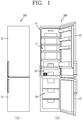
- FIG. 1 is a conceptual view of a refrigerator 100 in accordance with an embodiment of the present disclosure.
- FIG. 2 is a disassembled perspective view illustrating a structure related to the refrigerator 100 illustrated in FIG. 1 .
- the refrigerator 100 may include a refrigerator main body 10, a cold air passage duct 20, a control case 30, and a knob (shutter) 40.
- the refrigerator main body 10 may include a refrigerating chamber 11 and a freezing chamber 15.
- the refrigerator disclosed herein may be a bottom freezer type refrigerator.
- FIG. 1 illustrates the bottom freezer type refrigerator 100.
- a lower space is configured as the freezing chamber 15 and an upper space relative to the lower space is configured as the refrigerating chamber 11.
- a freezing chamber door 17 for opening and closing the freezing chamber 15 and a refrigerating chamber door 13 for opening and closing the refrigerating chamber 11 may be attached to the refrigerator main body 10.
- the present disclosure is preferably applied to the bottom freezer type refrigerator, but is not limited thereto. It is understood that the present disclosure may be applied to various types of refrigerators by adjusting an arrangement of the shutter 40, a cold air discharge opening 31, and the like, which are explained in more detail below.
- a chiller chamber drawer 18a may be attached to the lowermost end of the refrigerating chamber 11, and a chiller chamber cover 18b that forms an upper surface of a chiller chamber 18 may be attached to an upper portion of the chiller chamber drawer 18a.
- the chiller chamber drawer 18a and the chiller chamber cover 18b may be referred to as the chiller chamber 18.
- the chiller chamber 18 may store meat, and the like, and is preferably maintained at a relatively low temperature close to 0°C.
- a cold air passage duct 20 and the control case 30 may be provided at an upper portion of a rear surface of the chiller chamber drawer 18a and configured to communicate with the cold air discharge opening 31.
- the cold air passage duct 20 may be installed within the refrigerator main body 10.
- the cold air passage duct 20 may include a cold air passage 23 (see e.g., FIG. 6 ). As illustrated in FIGS. 1 and 2 , the cold air passage duct 20 may be disposed at a rear wall side of the refrigerating chamber 11 within the refrigerator main body to allow cold air to be discharged into the refrigerating chamber 11.
- Cold air generated in an evaporator may flow along the cold air passage 23 of the cold air passage duct 20.
- a refrigerating cycle is provided to supply cold air in response to a status change of a refrigerant.
- Components of the refrigerating cycle such as an evaporator, a compressor, a condenser, and an expansion valve, are components applied to a refrigerating cycle of a conventional refrigerator, so for convenience purposes a detailed description thereof is omitted.
- the control case 30 may be installed at one surface of the cold air passage duct 20.
- the control case 30 may be provided with the cold air discharge opening 31 through which cold air within the cold air passage duct 20 is discharged.
- the control case 30 may be understood as a plate structure coupled to one surface of the cold air passage duct 20. As illustrated in FIG. 2 , the control case 30 may be attached to a front surface of the cold air passage duct 20.
- a shutter accommodating portion 27 in which a shutter (knob) 40 is accommodated to be reciprocally movable may be formed in the cold air passage duct 20.
- the shutter accommodating portion 27 may be larger than the shutter 40, considering the coupling with the reciprocally-movable shutter 40.
- the shutter accommodating portion 27 may be provided with the cold air discharge opening 31 of the control case 30, which is explained below, and a cold air accommodating outlet 28 may be in communication with the cold air passage 23 disposed in the cold air passage duct 20.
- control case 30 A detailed structure of the control case 30 related to the present disclosure is described in more detail below, together with the description of the shutter 40, with reference to FIG. 5 .
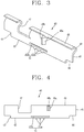
- FIG. 3 is a perspective view of the shutter 40 in accordance with an embodiment of the present disclosure.
- FIG. 4 is a front view of the shutter 40 illustrated in FIG. 3 .
- a structure of the shutter 40 will be described as illustrated in FIGS. 3 and 4 .
- the shutter 40 functions to open and/or close at least part of the cold air discharge opening 31 illustrated in FIG. 5 .
- the shutter 40 may be disposed between the cold air passage duct 20 and the control case 30.
- the shutter 40 may be installed at the control case 30 so as to be reciprocally movable in one direction.
- the shutter 40 may include a flow rate adjusting portion 41.
- the flow rate adjusting portion 41 may adjust a flow rate of cold air by adjusting a communicating area between a cut portion 47 (explained in more detail below) and the cold air discharge opening 31.
- the flow rate adjusting portion 41 may include a plurality of protrusions 41a and a slot 41b.
- the plurality of protrusions 41a may be disposed at a lower end portion of the shutter 40.
- the protrusions 41a may be spaced apart from one another by a preset distance.
- FIG. 3 illustrates one example showing three protrusions 41a at the lower end portion of the shutter 40.
- the plurality of protrusions 41a sequentially move over a pressing protrusion 33 (explained in more detail below). Accordingly, an opening and/or closing amount or level of the cold air discharge opening 31 may be adjusted.
- the slot 41b which is cut off in one direction may be formed at a position adjacent to the lower end portion of the shutter 40 with the plurality of protrusions 41a.
- the slot 41b may enable an elastic transformation of the lower end portion of the shutter 40 in a state in which the plurality of protrusions 41a are pressed by the pressing protrusion 33, thereby reducing a concentration of stress applied to the shutter 40 and the pressing protrusion 33 and minimizing a risk of damage.
- the slot 41b may be understood as an elastic space in which the lower end portion of the shutter 40 with the plurality of protrusions 41a is elastically transformed.
- FIGS. 3 and 4 illustrate one example in which the plurality of protrusions 41a protrude from the lower end portion of the shutter 40 with predetermined intervals from one another in a lengthwise direction.
- a plurality of protrusions 41c may be formed within a slot 41d, which is described in more detail below with reference to FIG. 11 .
- the shutter 40 may include first, second, third, and fourth movement limit end portions 42, 43, 44 and 45, a stopping/stepping portion 46a, a cut portion 47, and a bent portion 48.
- moving directions (up, down, left, right) of the shutter 40 are defined relative to the front view of FIG. 4 .
- the first movement limit end portion 42 is provided at a lower end of the shutter 40, and brought into contact with a first protruding portion 35 (explained in more detail below) so as to limit a downward movement of the shutter 40 and guide a lateral movement of the shutter 40.
- the first movement limit end portion 42 may be formed at a position adjacent to the plurality of protrusions 41a which downwardly protrude from the lower end portion of the shutter 40.
- the second movement limit end portion 43 is stopped by a second protruding portion 36 (explained in more detail below) so as to limit a movement of the shutter 40 in one side direction.
- the second movement limit end portion 43 may be formed in a manner of cutting off a lower end portion of one side of the shutter 40 to be connected to the first movement limit end portion 42.
- the drawing illustrates one example in which the second movement limit end portion 43 is formed by cutting off an edge portion of a left lower end of the shutter 40 and stopped by the second protruding portion 36 so as to limit a left movement of the shutter 40.
- the third movement limit end portion 44 may be formed by cutting off a lower end portion of another side of the shutter 40.
- the third movement limit end portion 44 is stopped by a third protruding portion 37 (explained in more detail below) so as to limit a downward movement of the shutter 40 and guide a lateral movement of the shutter 40.
- the drawing illustrates one example in which the third movement limit end portion 44 is formed by cutting off a right lower end portion of the shutter 40.
- the fourth movement limit end portion 45 may be connected to the third movement limit end portion 44.
- the fourth movement limit end portion 45 is stopped by a fourth protruding portion 38 to limit a movement of the shutter 40 in another side direction.
- the fourth movement limit end portion 45 may be understood as an end portion formed at a right side of the shutter 40.
- the stopping portion 46a may be formed to be bent from an upper end portion of the shutter 40 toward a shutter coupling portion 32 (see Fig. 5 ) so as to be slidably stopped in the shutter coupling portion 32.
- the stopping portion 46a may be formed to cover the shutter coupling portion 32 of the control case 30. Also, the stopping portion 46a enables the shutter 40 to be located between the control case 30 and the cold air passage duct 20.
- a shutter handle 46b may protrude from the stopping portion 46a toward a front side.
- a user may manipulate the shutter handle 46b in a generally left and right direction such that the shutter 40 can be slid. This enables the cut portion 47 of the shutter 40 to communicate with the cold air discharge opening 31, thereby adjusting the opening and closing amount of the cold air discharge opening 31.
- the shutter handle 46b may be disposed at a front side of the control case 30 to be manipulated by the user.
- FIG. 6 illustrates the structure in which the stopping portion 46a of the shutter 40 covers the control case 30 such that the shutter 40 is disposed between the control case 30 and the cold air passage duct 20.
- the cut portion 47 may be formed by cutting off at least part of an upper portion of the shutter 40 to communicate with the cold air discharge opening 31, such that at least part of one side of the cold air discharge opening 31 is open thereby to discharge the cold air.
- the cut portion 47 does not communicate with the cold air discharge opening 31 in a closed state of the cold air discharge opening 31, and at least part of the cut portion 47 may communicate with the cold air discharge opening 31 in an open state of the cold air discharge opening 31.
- a fifth movement limit end portion 49 may be formed at an upper end portion of the shutter 40.
- the fifth movement limit end portion 49 may be brought into contact with a limit rib 39 formed above the cold air discharge opening 31 to limit an upward movement of the shutter 40 and guide a lateral movement of the shutter 40.
- the fifth movement limit end portion 49 such as illustrated in FIG. 3 , may be formed at an end portion of a bent portion 48 (explained in more detail below).
- the fifth movement limit end portion 49 may be an upper end surface of the shutter 40 including a curved surface.
- the shutter 40 may include the bent portion 48 having an upper side formed in a bent shape.
- the shutter 40 may be coupled to the shutter coupling portion 32 and cover at least part of the shutter coupling portion 32.
- Such configuration may allow the shutter 40 to be more stably coupled to the control case 30. Also, with this structure, even when the shutter 40 is repetitively slid, stress which is concentrated on the shutter 40 may be dispersed, thereby improving durability.
- FIG. 5 is a conceptual view illustrating a correspondence between the control case 30 and the shutter 40 according to an embodiment of the present disclosure.
- FIG. 6 is a side sectional view taken along the line A-A' of FIG. 5 .
- a structure of the control case 30 and a coupling relationship between the control case 30 and the shutter 40 will be described with reference to FIGS. 5 and 6 .
- the control case 30 may be provided with a pressing protrusion 33.
- the pressing protrusion 33 may protrude from a lower portion of the cold air discharge opening 31 toward the cold air passage duct 20.
- the pressing protrusion 33 may press the plurality of protrusions 41a and be settled between the plurality of protrusions 41a, thereby adjusting the opening and closing amount of the cold air discharge opening 31.
- FIG. 5 illustrates one example of the pressing protrusion 33 that protrudes from the lower portion of the cold air discharge opening 31 formed on the control case 30 with being spaced apart from the lower portion by a predetermined distance.
- the control case 30 may include first and second protruding portions 35 and 36.
- the first protruding portion 35 may protrude from a left lower side of the cold air discharge opening 31 toward the cold air passage duct 20.
- the first protruding portion 35 may be brought into contact with the first movement limit end portion 42 located at the lower end of the shutter 40 so as to limit the downward movement of the shutter 40 and guide the lateral movement of the shutter 40.
- the second protruding portion 36 may be spaced apart from the first protruding portion 35 and protrude toward the cold air passage duct 20 so as to limit the lateral movement of the shutter 40.
- the second protruding portion 36 disposed at a left side of the pressing protrusion 33 may be stopped by the second movement limit end portion 43 so as to limit the left movement of the shutter 40.
- the control case 30 may further include third and fourth protruding portions 37 and 38.
- the third protruding portion 37 may protrude from a right lower side of the cold air discharge opening 31 toward the cold air passage duct 20.
- the third protruding portion 37 may be brought into contact with the third movement limit end portion 44 so as to limit the downward movement of the shutter 40 and guide the lateral movement of the shutter 40.
- the fourth protruding portion 38 may be disposed at a right side of the third protruding portion 37 with a spaced distance to limit the lateral movement of the shutter 40, and protrude toward the cold air passage duct 20.
- the fourth protruding portion 38 may be stopped by the fourth movement limit end portion 45 so as to limit the rightward movement of the shutter 40.
- the fourth protruding portion 38 is stopped by the fourth movement limit end portion 45 so as to limit the rightward movement of the shutter 40.
- the pressing protrusion 33 may be disposed below the cold air discharge opening 31 of the control case 30 and be spaced apart from the cold air discharge opening 31, the first and second protruding portions 35 and 36 may be sequentially disposed at the left side of the pressing protrusion 33, and the third and fourth protruding portions 37 and 38 may be sequentially disposed at the right side of the pressing protrusion 33.
- the control case 30 may further include the shutter coupling portion 32.
- the shutter coupling portion 32 may be formed between both sides of the cold air discharge opening 31 and be spaced apart from an upper portion of the cold air discharge opening 31 by a predetermined distance, so that a longitudinal slot 32a is obtained through which the stopping portion 46a runs and matures into the shutter handle 46b (see Figs. 5 and 6 )
- the cold air discharge opening 31 may be formed at each of both sides of the shutter coupling portion 32.
- the cold air discharge opening 31 formed at the left side of the control case 30 of FIG. 5 may be referred to as a first cold air discharge opening 31a
- the cold air discharge opening 31 formed at the right side of the control case 30 may be referred to as a second cold air discharge opening 31b.
- the first cold air discharge opening 31a may communicate with the cut portion 47 of the shutter 40 so as to be open.
- the fourth movement limit end portion 45 may open the second cold air discharge opening 31b.
- the first and second cold air discharge openings 31a and 31b may be opening and closing at the same time in response to the reciprocal movement of the shutter 40.
- the first and second cold air discharge openings 31a and 31b may be opened in a manner of always having the same area. More specifically, a width of the first cold air discharge opening 31a in a left and right direction may be the same as a width of the cut portion 47 in the left and right direction. Also, a distance from one end of a right side of the cut portion 47 to the fourth movement limit end portion 45 may be the same as a distance in the left and right direction of the shutter coupling portion 32 disposed between the first and second cold air discharge openings 31a and 31b.
- the cold air discharge opening 31 may be formed by dividing both sides thereof into the first and second cold air discharge openings 31a and 31b.
- the first and second cold air discharge openings 31a and 31b may always have the same area in the open state of the shutter 40. Such structure may prevent more cold air from being supplied through one side of the cold air discharge opening 31, and allow the cold air to be uniformly supplied into the refrigerating chamber 11.
- a limit rib 39 to limit the upward movement of the shutter 40 may protrude above the cold air discharge opening 31.
- the limit rib 39 may be brought into contact with the fifth movement limit end portion 49 located at the upper side of the shutter 40, to limit the upward movement of the shutter 40 and guide the lateral movement of the shutter 40.
- FIG. 7 is a conceptual view illustrating a closed state of the cold air discharge opening 31 by the shutter 40 in accordance with an embodiment of the present disclosure.
- FIG. 8 is a conceptual view illustrating a coupling relationship between the shutter 40 and the control case 30 in the state of FIG. 7 .
- FIG. 9 is a conceptual view illustrating an open state of the cold air discharge opening 31 by the shutter 40 according to the present disclosure.
- FIG. 10 is a conceptual view illustrating a coupling relationship between the shutter 40 and the control case 30 in the state of FIG. 9 .
- operations of the shutter 40 installed on the control case 30 related to the refrigerator 100 according to an embodiment of the present disclosure will be described with reference to FIGS. 5 , 7 , 8 , 9, and 10 .
- FIGS. 7 and 8 illustrate a state in which the shutter 40 is moved in an arrow direction and closes the first and second cold air discharge openings 31a and 31b.
- the fourth movement limit end portion 45 may be brought into contact with the fourth protruding portion 38
- the first and third movement limit end portions 42 and 44 may be brought into contact with the first and third protruding portions 35 and 37, respectively, so as to limit the downward movement of the shutter 40 and guide the lateral movement of the shutter 40.
- the second protruding portion 36 may be spaced apart from the second movement limit end portion 43.
- the first cold air discharge opening 31a may be closed by a portion of the shutter 40 located near the left side of the cut portion 47 of the shutter 40, and the second cold air discharge opening 31b may be closed by a portion of the shutter 40 located near the fourth movement limit end portion 45.
- FIGS. 9 and 10 illustrate a state in which the shutter 40 is moved in an arrow direction and opens the first and second cold air discharge openings 31a and 31b.
- the second movement limit end portion 43 may be brought into contact with the left second protruding portion 36, and the first and third movement limit end portions 42 and 44 may be brought into contact with the first and third protruding portions 35 and 37, to limit the downward movement of the shutter 40 and guide the lateral movement of the shutter 40.
- the fourth protruding portion 38 may be spaced apart from the fourth movement limit end portion 45.
- both of the first cold air discharge opening 31a and the second cold air discharge opening 31b are open.
- FIGS. 7, 8 , 9, and 10 illustrate examples in which the cold air discharge opening 31 is fully closed and fully opened. However, it is understood that the shutter 40 may be manipulated to open only a part of the cold air discharge opening 31. Even when the cold air discharge opening is only partially opened, the first cold air discharge opening 31a and the second cold air discharge opening 31b have the same area.
- One of the plurality of protrusions 41a may be pressed by the pressing protrusion 33 and another one of the plurality of protrusions 41a may move over the pressing protrusion 33.
- the one protrusion of the plurality of protrusions 41a is pressed by the pressing protrusion 33, the lower end portion of the shutter 40 is elastically transformed upwardly.
- the cold air discharge opening 31 is adjusted to be open by a predetermined area.
- FIG. 11 is a front view of the shutter 40 in accordance with another embodiment of the present disclosure.
- the shutter 40 of FIG. 11 is configured to open and close at least part of the cold air discharge opening 31.
- the shutter 40 may be disposed between the cold air passage duct 20 and the control case 30, and installed on the control case 30 to be reciprocally movable in one direction.
- the shutter 40 may include the flow rate adjusting portion 41.
- the flow rate adjusting portion 41 can adjust the flow rate of cold air by adjusting a communicating area between the cut portion 47 and the cold air discharge opening 31.
- the flow rate adjusting portion 41 may include a plurality of protrusions 41c and a slot 41d.
- the shutter according to the embodiment illustrated in FIG. 11 is different than the shutter according to the embodiment illustrated in FIG. 5 regarding the plurality of protrusions 41c and the slot 41d.
- the plurality of protrusions 41a are disposed at the lower end portion of the shutter 40 with being spaced apart from one another by the preset intervals
- the plurality of protrusions 41c according to the shutter of FIG. 11 upwardly protrude from a lower side within the slot 41d.
- the slot 41d which is cut in one direction is formed at a position adjacent to a lower end of the shutter 40. Also, FIG. 11 illustrates that the protrusions 41c of the shutter 40 upwardly protrude from the lower side within the slot 41d.
- the pressing protrusion 33 of the control case 30 may be disposed to be inserted into the slot 41d so as to press the plurality of protrusions 41c.
- the plurality of protrusions 41c are pressed by the pressing protrusion which is inserted into the slot 41d, the lower end portion of the shutter 40 is elastically transformed downwardly.
- the slot 41d may be understood as an elastic space in which the lower end of the shutter 40 is elastically transformed.
- the plurality of protrusions 41c may be sequentially moved over the pressing protrusion 33 while the shutter 40 moves in one direction, and the pressing protrusion 33 may be disposed between the protrusions 41c. Accordingly, an opening and closing amount of the cold air discharge opening 31 is adjusted.
- the slot 41d may allow for the elastic transformation of the lower end portion of the shutter 40 in the state in which the plurality of protrusions 41c are pressed by the pressing protrusion 33, thereby reducing a concentration of stress applied to the shutter 40 and the pressing protrusion 33 and minimizing a risk of damage.
- the pressing protrusion may be provided on the control case and the flow rate adjusting portion pressed by the pressing protrusion may be provided on the shutter, which may allow for adjusting an opening and closing amount of the cold air discharge opening in a manual manner.
- the shutter coupling portion may be formed on the cold air discharge opening and the stopping portion may be slidably coupled to the shutter coupling portion, thereby enabling a manual manipulation of the shutter. This may result in reducing power consumption and material costs and implementing user-desired temperature.
- both sides of the cold air discharge opening which are adjacent to the shutter coupling portion may always have the same area in an open state of the shutter, thereby uniformly supplying cold air into a refrigerating chamber through the both sides of the cold air discharge opening.
Landscapes
- Engineering & Computer Science (AREA)
- Chemical & Material Sciences (AREA)
- Combustion & Propulsion (AREA)
- Physics & Mathematics (AREA)
- Mechanical Engineering (AREA)
- Thermal Sciences (AREA)
- General Engineering & Computer Science (AREA)
- Cold Air Circulating Systems And Constructional Details In Refrigerators (AREA)
Claims (14)
- Kühlschrank (100), der Folgendes umfasst:einen Hauptkörper (10), der eine Kühlkammer (11) aufweist;eine Durchgangsleitung (20) für kalte Luft, die in dem Hauptkörper (10) angeordnet ist, wobei die Durchgangsleitung (20) für kalte Luft einen Durchgang (23) für kalte Luft aufweist, um kalte Luft in die Kühlkammer (11) abzuführen;ein Steuergehäuse (30), das an einer Oberfläche der Durchgangsleitung (20) für kalte Luft befestigt ist, wobei das Steuergehäuse (30) eine Austrittsöffnung (31) für kalte Luft aufweist, durch die die kalte Luft abgeführt wird; undeine Klappe (40), die in einer Richtung hin und her bewegt werden kann, um wenigstens einen Teil der Austrittsöffnung (31) für kalte Luft zu öffnen und zu schließen,wobei das Steuergehäuse (30) einen Druckvorsprung (33) umfasst, um gegen einen unteren Endabschnitt der Klappe (40) zu drücken, wobei der Druckvorsprung (33) unter der Austrittsöffnung (31) für kalte Luft vorgesehen ist und zu der Durchgangsleitung (20) für kalte Luft vorsteht,wobei die Klappe (40) einen Abschnitt (41) zum Einstellen einer Durchflussmenge umfasst, um einen Öffnungs- und Schließgrad der Austrittsöffnung (31) für kalte Luft in Reaktion darauf, dass er durch den Druckvorsprung (33) gedrückt wird, einzustellen, dadurch gekennzeichnet, dass die Klappe (40) zwischen der Durchgangsleitung (20) für kalte Luft und dem Steuergehäuse (30) vorgesehen ist,wobei der Abschnitt (41) zum Einstellen der Durchflussmenge Folgendes umfasst:mehrere Vorsprünge (41a; 41c), die an dem unteren Endabschnitt der Klappe (40) angeordnet sind, die mit einem vorgegebenen Abstand voneinander beabstandet sind, undeinen Spalt (41b; 41d), der weggeschnitten ist, um eine elastische Umformung des unteren Endabschnitts der Klappe (40) zu ermöglichen, wenn die Vorsprünge (41a; 41c) durch den Druckvorsprung (33) gedrückt werden.
- Kühlschrank nach Anspruch 1, wobei das Steuergehäuse (30) Folgendes umfasst:einen ersten vorstehenden Abschnitt (35), der unter einer ersten Seite (31a) der Austrittsöffnung (31) für kalte Luft vorgesehen ist und zu der Durchgangsleitung (20) für kalte Luft vorsteht, wobei der erste vorstehende Abschnitt (35) mit dem unteren Ende der Klappe (40) in Kontakt ist, um eine Abwärtsbewegung der Klappe (40) zu begrenzen und eine seitliche Bewegung der Klappe (40) zu führen; undeinen zweiten vorstehenden Abschnitt (36), der an einer Seite des Druckvorsprungs (33) vorgesehen ist und zu der Durchgangsleitung (20) für kalte Luft vorsteht, um die seitliche Bewegung der Klappe (40) zu begrenzen, wobei der zweite vorstehende Abschnitt (36) so positioniert ist, dass der erste vorstehende Abschnitt (35) zwischen dem Druckvorsprung (33) und dem zweiten vorstehenden Abschnitt (36) angeordnet ist.
- Kühlschrank nach Anspruch 2, wobei die Klappe (40) Folgendes umfasst:einen ersten Endabschnitt (42) zur Bewegungsbegrenzung, der an dem unteren Endabschnitt der Klappe (40) vorgesehen ist, wobei der erste Endabschnitt (42) zur Bewegungsbegrenzung mit dem ersten vorstehenden Abschnitt (35) in Kontakt ist, um die Abwärtsbewegung der Klappe (40) zu begrenzen und die seitliche Bewegung der Klappe (40) zu führen; undeinen zweiten Endabschnitt (43) zur Bewegungsbegrenzung, der an einem unteren Endabschnitt einer ersten Seite der Klappe (40) ausgebildet ist, wobei der zweite Endabschnitt (43) zur Bewegungsbegrenzung mit dem ersten Endabschnitt (42) zur Bewegungsbegrenzung verbunden ist und mit dem zweiten vorstehenden Abschnitt (36) in Kontakt ist, um eine Bewegung der Klappe (40) in Richtung einer ersten Seite zu begrenzen.
- Kühlschrank nach Anspruch 1, 2 oder 3, wobei das Steuergehäuse (30) ferner Folgendes umfasst:einen dritten vorstehenden Abschnitt (37), der unter einer zweiten Seite (31b) der Austrittsöffnung (31) für kalte Luft vorgesehen ist und zu der Durchgangsleitung (20) für kalte Luft vorsteht, wobei der dritte vorstehende Abschnitt (37) wenigstens mit einem Teil der Klappe (40) in Kontakt ist, um die Abwärtsbewegung der Klappe (40) zu begrenzen und die seitliche Bewegung der Klappe (40) zu führen; undeinen vierten vorstehenden Abschnitt (38), der zu der Durchgangsleitung (20) für kalte Luft vorsteht, um die seitliche Bewegung der Klappe (40) zu begrenzen, wobei der vierte vorstehende Abschnitt (38) so positioniert ist, dass der dritte vorstehende Abschnitt (37) zwischen dem Druckvorsprung (33) und dem vierten vorstehenden Abschnitt (38) angeordnet ist.
- Kühlschrank nach Anspruch 4, wobei die Klappe (40) ferner Folgendes umfasst:einen dritten Endabschnitt (44) zur Bewegungsbegrenzung, der an einem unteren Endabschnitt einer zweiten Seite der Klappe (40) ausgebildet ist, wobei der dritte Endabschnitt (44) zur Bewegungsbegrenzung mit dem dritten vorstehenden Abschnitt (37) in Kontakt ist, um die Abwärtsbewegung der Klappe (40) zu begrenzen und die seitliche Bewegung der Klappe (40) zu führen; undeinen vierten Endabschnitt (45) zur Bewegungsbegrenzung, der an der zweiten Seite der Klappe (40) vorgesehen ist, wobei der vierte Endabschnitt (45) zur Bewegungsbegrenzung mit dem dritten Endabschnitt (44) zur Bewegungsbegrenzung verbunden ist und mit dem vierten vorstehenden Abschnitt (38) in Kontakt ist, um eine Bewegung der Klappe (40) in Richtung einer zweiten Seite zu begrenzen.
- Kühlschrank nach einem der Ansprüche 1 bis 5, wobei eine Kältekammer (18) an dem untersten Abschnitt der Kühlkammer (11) vorgesehen ist, wobei das Steuergehäuse (30), das die Austrittsöffnung (31) für kalte Luft aufweist, angrenzend an die Kältekammer (18) vorgesehen ist, und wobei die Austrittsöffnung (31) für kalte Luft kommunizierend mit einem Einlass der Kältekammer (18) gekoppelt ist, um die kalte Luft in die Kältekammer (18) zuzuführen.
- Kühlschrank nach einem der Ansprüche 1 bis 6, wobei das Steuergehäuse (30) ferner einen Klappenkopplungsabschnitt (32) umfasst, der zwischen einer ersten Seite (31a) und einer zweiten Seite (31b) der Austrittsöffnung (31) für kalte Luft ausgebildet ist, wobei der Klappenkopplungsabschnitt (32) von einem oberen Abschnitt der Austrittsöffnung (31) für kalte Luft mit einem vorgegebenen Abstand beabstandet ist, wodurch die Klappe (40) mit dem Steuergehäuse (30) gleitfähig gekoppelt ist.
- Kühlschrank nach Anspruch 7, wobei die Klappe (40) ferner einen Stoppabschnitt umfasst, wobei der Stoppabschnitt (46a) ein oberer Endabschnitt der Klappe (40) ist, der in Richtung des Klappenkopplungsabschnitts (32) gebogen ist, wodurch die Klappe (40) mit dem Klappenkopplungsabschnitt (32) gleitfähig gekoppelt ist.
- Kühlschrank nach einem der Ansprüche 2 bis 8, wobei die Klappe (40) ferner einen ausgeschnittenen Abschnitt (47) umfasst, wobei der ausgeschnittene Abschnitt (47) durch Ausschneiden wenigstens eines Teils eines oberen Abschnitts der Klappe (40) gebildet wird, wodurch der ausgeschnittene Abschnitt (47) mit der Austrittsöffnung (31) für kalte Luft kommunizierend so gekoppelt ist, dass die kalte Luft durch Öffnen wenigstens eines Teils der ersten Seite (31a) oder der zweiten Seite (31b) der Austrittsöffnung (31) für kalte Luft abgeführt wird,
wobei die Austrittsöffnung (31) für kalte Luft an beiden Seiten des Klappenkopplungsabschnitts (32) angeordnet ist und wobei die erste (31a) und die zweite (31b) Seite der Austrittsöffnung (31) für kalte Luft so konfiguriert sind, dass sie die kalte Luft dort hindurch so abführen, dass die erste oder die zweite Austrittsöffnung (31a, 31b) für kalte Luft offen ist, während die jeweils andere der ersten und der zweiten Austrittsöffnung (31a, 31b) für kalte Luft in Reaktion darauf, dass wenigstens ein Teil der jeweils anderen der ersten und der zweiten Austrittsöffnung (31a, 31b) für kalte Luft mit dem ausgeschnittenen Abschnitt (47) kommuniziert, offen ist. - Kühlschrank nach Anspruch 9, wobei die erste und die zweite Austrittsöffnung (31a, 31b) für kalte Luft in einem Zustand, in dem sie durch die Klappe (40) geöffnet und geschlossen werden, die gleiche Fläche haben, wodurch kalte Luft durch die erste und die zweite Austrittsöffnung (31a, 31b) für kalte Luft gleichmäßig in die Kühlkammer (11) zugeführt werden kann.
- Kühlschrank nach einem der Ansprüche 1 bis 10, wobei die mehreren Vorsprünge (41c) von einer unteren Seite in dem Spalt (41d) nach oben vorstehen, um den unteren Endabschnitt der Klappe (40) in einem Zustand, in dem einer der mehreren Vorsprünge (41c) durch den Druckvorsprung (33) gedrückt wird, in einer Abwärtsrichtung elastisch umzuformen.
- Kühlschrank nach einem der Ansprüche 1 bis 10, wobei die mehreren Vorsprünge (41a) von dem unteren Endabschnitt der Klappe (40) nach unten vorstehen, um den unteren Endabschnitt der Klappe (40) in einem Zustand, in dem einer der mehreren Vorsprünge (41a) durch den Druckvorsprung (33) gedrückt wird, in einer Aufwärtsrichtung elastisch umzuformen.
- Kühlschrank nach einem der Ansprüche 2 bis 12, wobei der erste vorstehende Abschnitt (35) direkt unter der ersten Seite (31a) der Austrittsöffnung (31) für kalte Luft vorgesehen ist, und wobei der dritte vorstehende Abschnitt (37) direkt unter der zweiten Seite (31b) der Austrittsöffnung (31) für kalte Luft vorgesehen ist.
- Kühlschrank nach einem der Ansprüche 1 bis 13, wobei ein Öffhungs- und Schließgrad der Austrittsöffnung (31) für kalte Luft mit der Anzahl von Vorsprüngen (41a; 41c), die an dem unteren Endabschnitt der Klappe (40) angeordnet sind, und mit einem Abstand zwischen den Vorsprüngen (41a; 41c) korreliert.
Applications Claiming Priority (1)
| Application Number | Priority Date | Filing Date | Title |
|---|---|---|---|
| KR1020150129241A KR101815580B1 (ko) | 2015-09-11 | 2015-09-11 | 냉장고 |
Publications (2)
| Publication Number | Publication Date |
|---|---|
| EP3141848A1 EP3141848A1 (de) | 2017-03-15 |
| EP3141848B1 true EP3141848B1 (de) | 2018-06-06 |
Family
ID=56851499
Family Applications (1)
| Application Number | Title | Priority Date | Filing Date |
|---|---|---|---|
| EP16186489.7A Active EP3141848B1 (de) | 2015-09-11 | 2016-08-31 | Kühlschrank |
Country Status (4)
| Country | Link |
|---|---|
| US (2) | US10371433B2 (de) |
| EP (1) | EP3141848B1 (de) |
| KR (1) | KR101815580B1 (de) |
| CN (2) | CN110425799B (de) |
Families Citing this family (7)
| Publication number | Priority date | Publication date | Assignee | Title |
|---|---|---|---|---|
| CN110131956B (zh) * | 2018-02-08 | 2021-03-23 | 海尔智家股份有限公司 | 一种风道组件和具有其的风冷冰箱 |
| JP2020008191A (ja) * | 2018-07-04 | 2020-01-16 | 東芝ライフスタイル株式会社 | 冷蔵庫 |
| KR102540352B1 (ko) * | 2018-07-30 | 2023-06-07 | 삼성전자주식회사 | 냉장고 |
| US11674734B2 (en) | 2020-04-20 | 2023-06-13 | Electrolux Home Products, Inc. | Thermal mass for preserving food in functional compartments |
| KR102405364B1 (ko) * | 2020-06-03 | 2022-06-07 | 엘지전자 주식회사 | 히든 디스플레이를 가지는 냉장고 |
| KR20230038046A (ko) * | 2021-09-10 | 2023-03-17 | 삼성전자주식회사 | 냉장고 |
| KR20240109530A (ko) * | 2023-01-04 | 2024-07-11 | 삼성전자주식회사 | 냉장고 |
Family Cites Families (48)
| Publication number | Priority date | Publication date | Assignee | Title |
|---|---|---|---|---|
| US1943646A (en) | 1931-12-09 | 1934-01-16 | Paul C Warren | Refrigerator |
| US2255503A (en) | 1939-10-26 | 1941-09-09 | Gen Electric | Ventilated food storage receptacle |
| US2846934A (en) * | 1953-08-10 | 1958-08-12 | Garrett Corp | Cabin pressure outflow valve |
| US3192613A (en) * | 1961-05-16 | 1965-07-06 | Cameron Iron Works Inc | Valve and method of installing same |
| US3866437A (en) * | 1973-09-10 | 1975-02-18 | Westinghouse Electric Corp | Adjustable damper control mechanism |
| JPS5914689Y2 (ja) | 1979-08-20 | 1984-04-28 | 三洋電機株式会社 | 冷蔵庫 |
| US4250719A (en) * | 1979-09-04 | 1981-02-17 | General Electric Company | Household refrigerator humidity controlled pan assembly |
| US4802040A (en) * | 1984-04-05 | 1989-01-31 | Kabushiki Kaisha Sankyo Seiki Seisakusho | Disk-type recording and reproducing apparatus |
| KR910005176Y1 (ko) | 1986-01-15 | 1991-07-20 | 삼성전자 주식회사 | 냉장고의 냉기 분출량 조절장치 |
| JPS63123971A (ja) | 1986-11-12 | 1988-05-27 | 株式会社日立製作所 | 冷凍冷蔵庫 |
| JPS63123971U (de) | 1987-02-03 | 1988-08-12 | ||
| KR900005682B1 (ko) | 1987-12-18 | 1990-08-06 | 삼성전자 주식회사 | 냉장고의 냉장실 및 특정냉장실의 온도조절장치 |
| US4914928A (en) * | 1988-08-29 | 1990-04-10 | Whirlpool Corporation | Manual air damper control for a refrigerator |
| JPH0645820Y2 (ja) | 1988-11-04 | 1994-11-24 | 松下冷機株式会社 | 冷蔵庫 |
| US4850206A (en) | 1988-11-18 | 1989-07-25 | Amana Refrigeration, Inc. | Crisper humidity control |
| JPH0827125B2 (ja) * | 1989-06-23 | 1996-03-21 | ホシザキ電機株式会社 | 冷蔵庫 |
| KR950008222Y1 (ko) | 1989-08-31 | 1995-10-04 | 엘지전자 주식회사 | 광학식 뷰파인더 |
| KR920002386Y1 (ko) * | 1990-03-30 | 1992-04-10 | 삼성전자 주식회사 | 냉장고의 냉기 공급 안내 장치 |
| KR920007626B1 (ko) * | 1990-10-24 | 1992-09-09 | 대우전자 주식회사 | 냉장고의 온도조절 댐퍼 구동기구와 그 제어방법 및 제어장치 |
| KR0113426Y1 (ko) | 1993-09-14 | 1998-04-13 | 김광호 | 냉장고의 냉기공급 조절장치 |
| US5375413A (en) * | 1994-01-07 | 1994-12-27 | Paragon Electric Company, Inc. | Air baffle apparatus |
| CN1122674A (zh) * | 1994-06-23 | 1996-05-22 | 日本技术株式会社 | 开式陈列柜和出售机及其所用的致冷方法和装置 |
| JPH08296943A (ja) * | 1995-04-28 | 1996-11-12 | Toshiba Corp | 冷蔵庫 |
| US5884496A (en) | 1995-11-25 | 1999-03-23 | Lg Electronics, Inc. | Cool air feeding system for refrigerator |
| US5946935A (en) | 1997-08-22 | 1999-09-07 | Samsung Electronics Co., Ltd. | Refrigerator with a discharge member for changing a discharge position of cool air |
| KR100254409B1 (ko) | 1997-08-29 | 2000-05-01 | 구자홍 | 냉장고의 집중식 냉기공급장치 |
| JP3583603B2 (ja) * | 1997-12-26 | 2004-11-04 | 株式会社三協精機製作所 | 開閉部材の駆動方法 |
| JP3724978B2 (ja) * | 1999-04-22 | 2005-12-07 | 日本電産サンキョー株式会社 | ダブルダンパー装置 |
| KR20010090935A (ko) * | 2000-04-08 | 2001-10-22 | 구자홍 | 냉장고 |
| KR100445467B1 (ko) * | 2001-04-20 | 2004-08-21 | 주식회사 엘지이아이 | 공기조화기의 실내기 |
| DE10145141A1 (de) * | 2001-09-13 | 2003-04-03 | Bsh Bosch Siemens Hausgeraete | Kältegerät mit Kühlluftzirkulation |
| JP3807305B2 (ja) * | 2001-12-28 | 2006-08-09 | ダイキン工業株式会社 | 空気調和機 |
| DE10236210A1 (de) | 2002-08-07 | 2004-03-04 | BSH Bosch und Siemens Hausgeräte GmbH | Kältergerät mit unterteiltem Innenraum |
| US6904761B2 (en) * | 2003-03-11 | 2005-06-14 | General Electric Company | Method and apparatus to control humidity in a refrigerator |
| KR100523580B1 (ko) | 2003-08-13 | 2005-10-25 | 현대모비스 주식회사 | 글로브 박스용 쿨 박스의 개폐구조 |
| DE102006040379A1 (de) * | 2006-08-29 | 2008-03-06 | BSH Bosch und Siemens Hausgeräte GmbH | Kältegerät mit zwangsbelüftetem Verflüssiger |
| CN101231073B (zh) | 2007-01-25 | 2011-03-30 | 泰州乐金电子冷机有限公司 | 电冰箱用冷气供应结构 |
| MX2007016337A (es) * | 2007-12-18 | 2009-06-18 | Mabe Sa De Cv | Damper. |
| KR101559788B1 (ko) | 2009-01-30 | 2015-10-13 | 엘지전자 주식회사 | 냉장고 |
| KR101615373B1 (ko) | 2009-03-25 | 2016-04-25 | 동부대우전자 주식회사 | 가변 가이드를 갖는 냉장고 멀티 덕트 |
| KR101577634B1 (ko) | 2009-10-07 | 2015-12-15 | 현대모비스 주식회사 | 에어벤트 풍향조절장치 |
| US8550290B1 (en) * | 2012-06-26 | 2013-10-08 | Robert L. Davis | Portable storage system comprising a means for adjustable ventilation |
| ITTO20121038A1 (it) | 2012-12-03 | 2014-06-04 | Elbi Int Spa | Dispositivo valvolare per il controllo di un flusso di fluido, in particolare per il controllo del flusso di aria fredda in un apparecchio elettrodomestico, quale un frigorifero. |
| US9970699B2 (en) * | 2013-08-26 | 2018-05-15 | Whirlpool Corporation | Combined refrigerator/freezer appliances with dampers having ice prevention treatments |
| PL3201543T3 (pl) | 2014-10-02 | 2019-04-30 | Arcelik As | Lodówka zawierająca komorę specjalną z kontrolą wilgotności i temperatury |
| KR101861279B1 (ko) * | 2015-09-21 | 2018-05-25 | 엘지전자 주식회사 | 냉장고 및 냉장고의 냉기 유량 모니터링 시스템 |
| CN105716353B (zh) | 2016-02-02 | 2019-04-26 | 海信(山东)冰箱有限公司 | 一种风冷冰箱的风道组件及风冷冰箱 |
| US20170227276A1 (en) * | 2016-02-04 | 2017-08-10 | Robertshaw Controls Company | Rotary damper |
-
2015
- 2015-09-11 KR KR1020150129241A patent/KR101815580B1/ko not_active Expired - Fee Related
-
2016
- 2016-08-23 US US15/244,865 patent/US10371433B2/en active Active
- 2016-08-31 EP EP16186489.7A patent/EP3141848B1/de active Active
- 2016-09-09 CN CN201910700332.3A patent/CN110425799B/zh active Active
- 2016-09-09 CN CN201610814658.5A patent/CN106907893B/zh active Active
-
2019
- 2019-07-11 US US16/509,191 patent/US11408662B2/en active Active
Non-Patent Citations (1)
| Title |
|---|
| None * |
Also Published As
| Publication number | Publication date |
|---|---|
| EP3141848A1 (de) | 2017-03-15 |
| KR101815580B1 (ko) | 2018-01-05 |
| US11408662B2 (en) | 2022-08-09 |
| CN106907893B (zh) | 2019-09-10 |
| KR20170031543A (ko) | 2017-03-21 |
| US20170074576A1 (en) | 2017-03-16 |
| US10371433B2 (en) | 2019-08-06 |
| CN106907893A (zh) | 2017-06-30 |
| CN110425799B (zh) | 2021-08-27 |
| US20190331394A1 (en) | 2019-10-31 |
| CN110425799A (zh) | 2019-11-08 |
Similar Documents
| Publication | Publication Date | Title |
|---|---|---|
| EP3141848B1 (de) | Kühlschrank | |
| US11573046B2 (en) | Refrigerator | |
| CN108266948B (zh) | 冰箱 | |
| KR100889821B1 (ko) | 온도조절 챔버를 구비한 냉장고 | |
| EP3144611B1 (de) | Kühlschrank und kühlluftstromüberwachungssystem dafür | |
| KR20160148225A (ko) | 냉장고 | |
| US11828517B2 (en) | Single air passageway and damper assembly in a variable climate zone compartment | |
| AU2018410666B2 (en) | Air passageways in a variable climate zone compartment | |
| EP3106785A1 (de) | Eisherstellungsleitung für einen kühlschrank und eisherstellungsverfahren damit | |
| KR101615373B1 (ko) | 가변 가이드를 갖는 냉장고 멀티 덕트 | |
| US11747074B2 (en) | Heater in a variable climate zone compartment | |
| KR20070023901A (ko) | 양문형 냉장고의 야채실 온도 독립제어장치 | |
| KR102455074B1 (ko) | 냉장고 | |
| EP3106788A1 (de) | Kühlschrank, eiserzeuger und verfahren zur desodorierung davon | |
| KR20150114722A (ko) | 냉장고 | |
| KR20030038998A (ko) | 특선냉동부를 구비한 냉장고 |
Legal Events
| Date | Code | Title | Description |
|---|---|---|---|
| PUAI | Public reference made under article 153(3) epc to a published international application that has entered the european phase |
Free format text: ORIGINAL CODE: 0009012 |
|
| AK | Designated contracting states |
Kind code of ref document: A1 Designated state(s): AL AT BE BG CH CY CZ DE DK EE ES FI FR GB GR HR HU IE IS IT LI LT LU LV MC MK MT NL NO PL PT RO RS SE SI SK SM TR |
|
| AX | Request for extension of the european patent |
Extension state: BA ME |
|
| 17P | Request for examination filed |
Effective date: 20170725 |
|
| RBV | Designated contracting states (corrected) |
Designated state(s): AL AT BE BG CH CY CZ DE DK EE ES FI FR GB GR HR HU IE IS IT LI LT LU LV MC MK MT NL NO PL PT RO RS SE SI SK SM TR |
|
| GRAP | Despatch of communication of intention to grant a patent |
Free format text: ORIGINAL CODE: EPIDOSNIGR1 |
|
| RIC1 | Information provided on ipc code assigned before grant |
Ipc: F25D 17/04 20060101AFI20171117BHEP |
|
| INTG | Intention to grant announced |
Effective date: 20171206 |
|
| GRAS | Grant fee paid |
Free format text: ORIGINAL CODE: EPIDOSNIGR3 |
|
| GRAJ | Information related to disapproval of communication of intention to grant by the applicant or resumption of examination proceedings by the epo deleted |
Free format text: ORIGINAL CODE: EPIDOSDIGR1 |
|
| GRAL | Information related to payment of fee for publishing/printing deleted |
Free format text: ORIGINAL CODE: EPIDOSDIGR3 |
|
| GRAR | Information related to intention to grant a patent recorded |
Free format text: ORIGINAL CODE: EPIDOSNIGR71 |
|
| INTC | Intention to grant announced (deleted) | ||
| GRAA | (expected) grant |
Free format text: ORIGINAL CODE: 0009210 |
|
| INTG | Intention to grant announced |
Effective date: 20180418 |
|
| AK | Designated contracting states |
Kind code of ref document: B1 Designated state(s): AL AT BE BG CH CY CZ DE DK EE ES FI FR GB GR HR HU IE IS IT LI LT LU LV MC MK MT NL NO PL PT RO RS SE SI SK SM TR |
|
| REG | Reference to a national code |
Ref country code: GB Ref legal event code: FG4D |
|
| REG | Reference to a national code |
Ref country code: CH Ref legal event code: EP Ref country code: AT Ref legal event code: REF Ref document number: 1006556 Country of ref document: AT Kind code of ref document: T Effective date: 20180615 |
|
| REG | Reference to a national code |
Ref country code: IE Ref legal event code: FG4D |
|
| REG | Reference to a national code |
Ref country code: DE Ref legal event code: R096 Ref document number: 602016003325 Country of ref document: DE |
|
| REG | Reference to a national code |
Ref country code: NL Ref legal event code: MP Effective date: 20180606 |
|
| REG | Reference to a national code |
Ref country code: LT Ref legal event code: MG4D |
|
| PG25 | Lapsed in a contracting state [announced via postgrant information from national office to epo] |
Ref country code: BG Free format text: LAPSE BECAUSE OF FAILURE TO SUBMIT A TRANSLATION OF THE DESCRIPTION OR TO PAY THE FEE WITHIN THE PRESCRIBED TIME-LIMIT Effective date: 20180906 Ref country code: LT Free format text: LAPSE BECAUSE OF FAILURE TO SUBMIT A TRANSLATION OF THE DESCRIPTION OR TO PAY THE FEE WITHIN THE PRESCRIBED TIME-LIMIT Effective date: 20180606 Ref country code: FI Free format text: LAPSE BECAUSE OF FAILURE TO SUBMIT A TRANSLATION OF THE DESCRIPTION OR TO PAY THE FEE WITHIN THE PRESCRIBED TIME-LIMIT Effective date: 20180606 Ref country code: CY Free format text: LAPSE BECAUSE OF FAILURE TO SUBMIT A TRANSLATION OF THE DESCRIPTION OR TO PAY THE FEE WITHIN THE PRESCRIBED TIME-LIMIT Effective date: 20180606 Ref country code: ES Free format text: LAPSE BECAUSE OF FAILURE TO SUBMIT A TRANSLATION OF THE DESCRIPTION OR TO PAY THE FEE WITHIN THE PRESCRIBED TIME-LIMIT Effective date: 20180606 Ref country code: SE Free format text: LAPSE BECAUSE OF FAILURE TO SUBMIT A TRANSLATION OF THE DESCRIPTION OR TO PAY THE FEE WITHIN THE PRESCRIBED TIME-LIMIT Effective date: 20180606 Ref country code: NO Free format text: LAPSE BECAUSE OF FAILURE TO SUBMIT A TRANSLATION OF THE DESCRIPTION OR TO PAY THE FEE WITHIN THE PRESCRIBED TIME-LIMIT Effective date: 20180906 |
|
| PG25 | Lapsed in a contracting state [announced via postgrant information from national office to epo] |
Ref country code: RS Free format text: LAPSE BECAUSE OF FAILURE TO SUBMIT A TRANSLATION OF THE DESCRIPTION OR TO PAY THE FEE WITHIN THE PRESCRIBED TIME-LIMIT Effective date: 20180606 Ref country code: HR Free format text: LAPSE BECAUSE OF FAILURE TO SUBMIT A TRANSLATION OF THE DESCRIPTION OR TO PAY THE FEE WITHIN THE PRESCRIBED TIME-LIMIT Effective date: 20180606 Ref country code: LV Free format text: LAPSE BECAUSE OF FAILURE TO SUBMIT A TRANSLATION OF THE DESCRIPTION OR TO PAY THE FEE WITHIN THE PRESCRIBED TIME-LIMIT Effective date: 20180606 Ref country code: GR Free format text: LAPSE BECAUSE OF FAILURE TO SUBMIT A TRANSLATION OF THE DESCRIPTION OR TO PAY THE FEE WITHIN THE PRESCRIBED TIME-LIMIT Effective date: 20180907 |
|
| REG | Reference to a national code |
Ref country code: AT Ref legal event code: MK05 Ref document number: 1006556 Country of ref document: AT Kind code of ref document: T Effective date: 20180606 |
|
| PG25 | Lapsed in a contracting state [announced via postgrant information from national office to epo] |
Ref country code: NL Free format text: LAPSE BECAUSE OF FAILURE TO SUBMIT A TRANSLATION OF THE DESCRIPTION OR TO PAY THE FEE WITHIN THE PRESCRIBED TIME-LIMIT Effective date: 20180606 |
|
| PG25 | Lapsed in a contracting state [announced via postgrant information from national office to epo] |
Ref country code: AT Free format text: LAPSE BECAUSE OF FAILURE TO SUBMIT A TRANSLATION OF THE DESCRIPTION OR TO PAY THE FEE WITHIN THE PRESCRIBED TIME-LIMIT Effective date: 20180606 Ref country code: PL Free format text: LAPSE BECAUSE OF FAILURE TO SUBMIT A TRANSLATION OF THE DESCRIPTION OR TO PAY THE FEE WITHIN THE PRESCRIBED TIME-LIMIT Effective date: 20180606 Ref country code: CZ Free format text: LAPSE BECAUSE OF FAILURE TO SUBMIT A TRANSLATION OF THE DESCRIPTION OR TO PAY THE FEE WITHIN THE PRESCRIBED TIME-LIMIT Effective date: 20180606 Ref country code: SK Free format text: LAPSE BECAUSE OF FAILURE TO SUBMIT A TRANSLATION OF THE DESCRIPTION OR TO PAY THE FEE WITHIN THE PRESCRIBED TIME-LIMIT Effective date: 20180606 Ref country code: RO Free format text: LAPSE BECAUSE OF FAILURE TO SUBMIT A TRANSLATION OF THE DESCRIPTION OR TO PAY THE FEE WITHIN THE PRESCRIBED TIME-LIMIT Effective date: 20180606 Ref country code: EE Free format text: LAPSE BECAUSE OF FAILURE TO SUBMIT A TRANSLATION OF THE DESCRIPTION OR TO PAY THE FEE WITHIN THE PRESCRIBED TIME-LIMIT Effective date: 20180606 Ref country code: IS Free format text: LAPSE BECAUSE OF FAILURE TO SUBMIT A TRANSLATION OF THE DESCRIPTION OR TO PAY THE FEE WITHIN THE PRESCRIBED TIME-LIMIT Effective date: 20181006 |
|
| PG25 | Lapsed in a contracting state [announced via postgrant information from national office to epo] |
Ref country code: IT Free format text: LAPSE BECAUSE OF FAILURE TO SUBMIT A TRANSLATION OF THE DESCRIPTION OR TO PAY THE FEE WITHIN THE PRESCRIBED TIME-LIMIT Effective date: 20180606 Ref country code: SM Free format text: LAPSE BECAUSE OF FAILURE TO SUBMIT A TRANSLATION OF THE DESCRIPTION OR TO PAY THE FEE WITHIN THE PRESCRIBED TIME-LIMIT Effective date: 20180606 |
|
| REG | Reference to a national code |
Ref country code: DE Ref legal event code: R097 Ref document number: 602016003325 Country of ref document: DE |
|
| PG25 | Lapsed in a contracting state [announced via postgrant information from national office to epo] |
Ref country code: MC Free format text: LAPSE BECAUSE OF FAILURE TO SUBMIT A TRANSLATION OF THE DESCRIPTION OR TO PAY THE FEE WITHIN THE PRESCRIBED TIME-LIMIT Effective date: 20180606 |
|
| PLBE | No opposition filed within time limit |
Free format text: ORIGINAL CODE: 0009261 |
|
| STAA | Information on the status of an ep patent application or granted ep patent |
Free format text: STATUS: NO OPPOSITION FILED WITHIN TIME LIMIT |
|
| PG25 | Lapsed in a contracting state [announced via postgrant information from national office to epo] |
Ref country code: LU Free format text: LAPSE BECAUSE OF NON-PAYMENT OF DUE FEES Effective date: 20180831 |
|
| REG | Reference to a national code |
Ref country code: BE Ref legal event code: MM Effective date: 20180831 |
|
| 26N | No opposition filed |
Effective date: 20190307 |
|
| PG25 | Lapsed in a contracting state [announced via postgrant information from national office to epo] |
Ref country code: SI Free format text: LAPSE BECAUSE OF FAILURE TO SUBMIT A TRANSLATION OF THE DESCRIPTION OR TO PAY THE FEE WITHIN THE PRESCRIBED TIME-LIMIT Effective date: 20180606 Ref country code: DK Free format text: LAPSE BECAUSE OF FAILURE TO SUBMIT A TRANSLATION OF THE DESCRIPTION OR TO PAY THE FEE WITHIN THE PRESCRIBED TIME-LIMIT Effective date: 20180606 |
|
| PG25 | Lapsed in a contracting state [announced via postgrant information from national office to epo] |
Ref country code: BE Free format text: LAPSE BECAUSE OF NON-PAYMENT OF DUE FEES Effective date: 20180831 Ref country code: FR Free format text: LAPSE BECAUSE OF NON-PAYMENT OF DUE FEES Effective date: 20180831 |
|
| PG25 | Lapsed in a contracting state [announced via postgrant information from national office to epo] |
Ref country code: AL Free format text: LAPSE BECAUSE OF FAILURE TO SUBMIT A TRANSLATION OF THE DESCRIPTION OR TO PAY THE FEE WITHIN THE PRESCRIBED TIME-LIMIT Effective date: 20180606 |
|
| PG25 | Lapsed in a contracting state [announced via postgrant information from national office to epo] |
Ref country code: MT Free format text: LAPSE BECAUSE OF NON-PAYMENT OF DUE FEES Effective date: 20180831 |
|
| PG25 | Lapsed in a contracting state [announced via postgrant information from national office to epo] |
Ref country code: TR Free format text: LAPSE BECAUSE OF FAILURE TO SUBMIT A TRANSLATION OF THE DESCRIPTION OR TO PAY THE FEE WITHIN THE PRESCRIBED TIME-LIMIT Effective date: 20180606 |
|
| PG25 | Lapsed in a contracting state [announced via postgrant information from national office to epo] |
Ref country code: CH Free format text: LAPSE BECAUSE OF NON-PAYMENT OF DUE FEES Effective date: 20190831 Ref country code: LI Free format text: LAPSE BECAUSE OF NON-PAYMENT OF DUE FEES Effective date: 20190831 Ref country code: PT Free format text: LAPSE BECAUSE OF FAILURE TO SUBMIT A TRANSLATION OF THE DESCRIPTION OR TO PAY THE FEE WITHIN THE PRESCRIBED TIME-LIMIT Effective date: 20180606 |
|
| PG25 | Lapsed in a contracting state [announced via postgrant information from national office to epo] |
Ref country code: IE Free format text: LAPSE BECAUSE OF NON-PAYMENT OF DUE FEES Effective date: 20180831 Ref country code: MK Free format text: LAPSE BECAUSE OF NON-PAYMENT OF DUE FEES Effective date: 20180606 Ref country code: HU Free format text: LAPSE BECAUSE OF FAILURE TO SUBMIT A TRANSLATION OF THE DESCRIPTION OR TO PAY THE FEE WITHIN THE PRESCRIBED TIME-LIMIT; INVALID AB INITIO Effective date: 20160831 |
|
| REG | Reference to a national code |
Ref country code: DE Ref legal event code: R082 Ref document number: 602016003325 Country of ref document: DE Representative=s name: TER MEER STEINMEISTER & PARTNER PATENTANWAELTE, DE |
|
| PGFP | Annual fee paid to national office [announced via postgrant information from national office to epo] |
Ref country code: DE Payment date: 20250707 Year of fee payment: 10 |
|
| PGFP | Annual fee paid to national office [announced via postgrant information from national office to epo] |
Ref country code: GB Payment date: 20250707 Year of fee payment: 10 |