EP3142818B1 - Modulare schnittstelle für werkzeuge - Google Patents
Modulare schnittstelle für werkzeuge Download PDFInfo
- Publication number
- EP3142818B1 EP3142818B1 EP15736173.4A EP15736173A EP3142818B1 EP 3142818 B1 EP3142818 B1 EP 3142818B1 EP 15736173 A EP15736173 A EP 15736173A EP 3142818 B1 EP3142818 B1 EP 3142818B1
- Authority
- EP
- European Patent Office
- Prior art keywords
- assembly
- section
- pin
- interface according
- tool holder
- Prior art date
- Legal status (The legal status is an assumption and is not a legal conclusion. Google has not performed a legal analysis and makes no representation as to the accuracy of the status listed.)
- Active
Links
Images


Classifications
-
- B—PERFORMING OPERATIONS; TRANSPORTING
- B23—MACHINE TOOLS; METAL-WORKING NOT OTHERWISE PROVIDED FOR
- B23B—TURNING; BORING
- B23B31/00—Chucks; Expansion mandrels; Adaptations thereof for remote control
- B23B31/02—Chucks
- B23B31/10—Chucks characterised by the retaining or gripping devices or their immediate operating means
- B23B31/113—Retention by bayonet connection
-
- B—PERFORMING OPERATIONS; TRANSPORTING
- B23—MACHINE TOOLS; METAL-WORKING NOT OTHERWISE PROVIDED FOR
- B23B—TURNING; BORING
- B23B31/00—Chucks; Expansion mandrels; Adaptations thereof for remote control
- B23B31/02—Chucks
- B23B31/10—Chucks characterised by the retaining or gripping devices or their immediate operating means
-
- B—PERFORMING OPERATIONS; TRANSPORTING
- B23—MACHINE TOOLS; METAL-WORKING NOT OTHERWISE PROVIDED FOR
- B23B—TURNING; BORING
- B23B2231/00—Details of chucks, toolholder shanks or tool shanks
- B23B2231/12—Chucks having means to amplify the force produced by the actuating means to increase the clamping force
-
- B—PERFORMING OPERATIONS; TRANSPORTING
- B23—MACHINE TOOLS; METAL-WORKING NOT OTHERWISE PROVIDED FOR
- B23B—TURNING; BORING
- B23B2231/00—Details of chucks, toolholder shanks or tool shanks
- B23B2231/52—Chucks with means to loosely retain the tool or workpiece in the unclamped position
-
- B—PERFORMING OPERATIONS; TRANSPORTING
- B23—MACHINE TOOLS; METAL-WORKING NOT OTHERWISE PROVIDED FOR
- B23B—TURNING; BORING
- B23B31/00—Chucks; Expansion mandrels; Adaptations thereof for remote control
- B23B31/003—Work or tool ejection means
Definitions
- the invention relates to an interface according to the preamble of claim 1 consisting of a first assembly - holding a tool or a tool holder - and a second assembly - carrying a processing element, the first assembly having, on the one hand, a recess which has at least one truncated cone or cylindrical shell Section and on the other hand has a contact surface or contact point acting in the axial direction - in the direction of the second assembly - and the second assembly has a pin which, on the one hand, has a conical, truncated cone or cylindrical section for contact with the truncated cone or cylindrical section of the first assembly and, on the other hand, has at least one contact point or contact surface acting in the axial direction for contacting the contact surface or contact point of the first assembly.
- Such an interface is from the WO 2010/089405 A1 known.
- An annular shift lever element is arranged in a longitudinally displaceable or pivotable manner in the recess of the first assembly.
- the shift lever element has at least one articulation element - which articulates the second assembly.
- the second assembly has at least one rear grip element, which can be brought behind the articulation element of the shift lever element by a pivoting movement of the second assembly.
- a coupling for coupling a tool shaft to a machine shaft in which a more secure, easily releasable axial clamping and a secure cutting edge orientation can be achieved and tools with a screw connection can also be used.
- the machine shaft has a sleeve with a central bore for receiving a complementary end of the tool shaft.
- the sleeve has a flat outer edge and an inner section for centering the tool shank and a second outer section with opposite sectors with recessed oblique ramps.
- the tool shaft can be locked in a bayonet-like manner in the machine shaft, with the tool shaft with its flat flange against the flat edge of the sleeve and thus forms a tight, rigid unit that can withstand high torques resulting from the cutting work.
- the present invention is based on the problem of developing an interface from a first assembly and a second assembly which ensures easy handling with a high repeatability with regard to the position of the second assembly relative to the first assembly with each tool change - despite the small interface size.
- a bayonet-like closure with at least one web on the pin is arranged between the recess and the pin.
- a clamping element is arranged in the first assembly, the front end of which comes into contact with one of the webs during clamping.
- a second assembly is positioned so that it cannot rotate relative to a first assembly and is clamped with repeat accuracy.
- the solution is a bayonet-type lock.
- the second assembly which can be plugged into the first assembly, carries radially projecting elements such as webs, bolts, pins or the like.
- the first assembly has corresponding recesses or rear grips into which the protruding elements engage with one another under at least one translational and/or rotational movement when the two assemblies are coupled.
- the protruding elements contact the recesses or rear grips, for example in point, line or area-shaped contacts.
- the first assembly also houses a clamping element, with the help of which the coupling movement is supported and/or the coupling is locked. If necessary, the uncoupling process can also be initiated using the manually operated clamping element, for example.
- the protruding elements and the recesses or rear grips are mutually arranged in such a way that when uncoupling the second assembly cannot immediately fall out of the first after a first unclamping or releasing of the coupling. Another step is required to completely separate the assemblies.
- the first assembly is a rotating spindle head of a tool changing unit.
- the second assembly represents a tool-carrying tool holder.
- the first assembly can also be a non-rotating tool carrier, such as is used, for example, as a steel holder for an upper slide of a conventional lathe.
- the second assembly in this case is the in Turning steel arranged in a tool holder as a tool or cutting edge carrier.
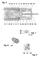
- the Figure 3 shows the front part of a tool unit.
- a spindle head (20) protrudes from its housing (10) as the first assembly of a modular interface.
- a replaceable tool holder (90) sits in the spindle head (20) as a second component of the modular interface.
- the tool holder (90) carries a twist drill, for example, as a tool (140).
- the housing (10) and the cover (13) support the rear end of the spindle head (20) in two shoulder ball bearings (11) arranged in an O-arrangement.
- the outer rings of the shoulder ball bearings (11) are axially fixed between the housing (10) and the cover (13).
- the inner rings of the bearings (11) mounted on the shaft (39) of the spindle head (20) are seated axially clamped between a spindle head shoulder (25) and a holding plate (12) which is axially screwed centrally to the spindle head (20) and centered in the inner ring of the contacted inclined shoulder bearing (11).
- the cover (13) of the housing (10) has an annular groove (16) on the front of its largely flat end face (15), in which a sealing ring (17) resting on the rear flat collar surface (26) of the spindle head (20) is inserted is.
- a tubular clamping gear section (21) protrudes from the housing (10) at the front of the spindle head (20).
- This tensioning gear section (21) has, for example, a cylindrical outer wall (22), cf. Figure 1 , a profiled inner wall (31) - as part of a recess (30) receiving a tool holder (90) - and a front, for example flat, end face (124).
- the depth of the clamping gear section (21) is 11.7 mm for a spindle head (20) with, for example, 22 mm outer diameter, while its average wall thickness is, for example, 4 mm.
- the inner wall (31) ends, for example, in front of a flat intermediate floor surface (28), in which a cylindrical bore (35) adjoins.
- This hole (35) has a diameter of 6 mm, for example.
- the depth of the hole (35) is approx. 2.8 mm.
- the hole (35) ends in a flat floor surface (29).
- the clamping gear section (21) of the spindle head (20) has, for example, a radial threaded bore (49), cf. Figure 21 .
- the threaded hole (49) has a fine thread M 8 x 0.5.
- the inner wall (31) is based on a central bore, the cylindrical wall of which has an inner diameter of, for example, 12 mm, cf. Figure 5 .
- a first milling (42) the cylinder jacket (43) of which covers the entire third quadrant.
- a quadrant is a term from mathematics. It is a section of a drawing plane bounded by two coordinate axes. Four quadrants cover 360 degrees, with the zero degree marking in the positive area of the abscissa of the coordinate system. The angle degrees are counted counterclockwise.
- the first milling (42) of the inner wall (31) has a radius of, for example, 4.5 mm. Its center line (45) is 3.6 mm from the center line (59). She's lying down Figure 5 at 225 degrees in the third quadrant.
- a second cutout (46) is opposite the first (42). It has the shape of a crescent-shaped elongated hole. The center line of the slot lies on a circle with a radius of 4.1 mm. The bore diameter of the elongated hole is 4 mm.
- the second cutout (46) covers, for example, 116.6 degrees of angle in the area of the full slot width. Both cutouts (42, 46) extend parallel to the center line (59) between the flat intermediate floor surface (28) and the outer cone section (120). In the second quadrant there is a slot (47) between the cutouts (42, 46).
- Another stud, the locking stud (48) is arranged between the cutouts (46, 42) in the fourth quadrant.
- the holding groove (51) has a clamping flank (52) which lies opposite the intermediate floor surface (28). It is, for example, a section of a thread groove flank whose pitch is, for example, 6 mm. In the exemplary embodiment it is part of a rectangular thread. It can also be part of a trapezoidal, saw, round, metric thread or the like.
- the retaining groove (51) covers approx. 60 degrees of angle the circumference of the inner wall (31).
- the maximum holding groove depth is, for example, 2.1 mm.
- the retaining groove (51) has a non-loaded flank (53), which is, for example, 3 mm away from the clamping flank (52). If necessary, the retaining groove (51) can extend to the intermediate floor surface (28) without the flank (53).
- An eccentric screw (60) equipped with an external thread is screwed into the threaded hole (49) of the clamping gear section (21). It has a front end which projects into the recess (30) and is designed as an eccentric pin (65), see also Figure 7 .
- the latter has a cylindrical outer surface with a diameter of, for example, 4.8 mm. If necessary, this outer surface can also be convex, for example spherically curved, at least in some areas.
- the eccentricity of the eccentric pin (65) is, for example, 0.875 ⁇ 0.1 mm.
- the pivot axis of the eccentric screw (60) is its center line (69).
- the eccentric pin-free end face of the eccentric screw (60) has a tool recess (67), cf. Figure 20 , for example with a hexagonal hollow cross section. Between the tool recess (67) and the external thread of the eccentric screw (60), a groove (68) or notch, for example 0.5 mm deep, extends in the radial direction to mark the position of the eccentric shaft (61), cf. Figure 2 .
- the groove (68) is seated Figure 2 below the tool recess (67).
- the tool holder (90) is located in the recess (30).
- the latter has a flange section (91), cf. Figure 11 , on which a pin (100) is formed.
- This pin (100) comprises an outer cone section (120), a locking section (101) and an end section (127).
- the almost disc-shaped flange section (91) has a cylindrical outer surface, the diameter of which is, for example, slightly smaller than the adjacent outer diameter of the spindle head (20).
- the flange section (91) has, for example, a flat end face (95), in the middle of which a recess (95) is arranged for receiving a collet chuck (130), another tool-holding component or a tool itself.
- the flange section (91) ends in a contact surface (121) designed as a flat collar surface.
- the outer surface of the flange section (91) points close to the collar surface (121), cf. Figure 21 , a marking groove (122).
- the collet recess (95) in the end face (92) essentially comprises an internal thread section (96) and an internal cone section (97).
- the 6.5 mm deep internal thread section (96) for example, has the fine thread M18 x 1.
- the inner cone section (97) has a cone angle of, for example, 16 degrees with a maximum inner diameter of 11 mm. It is 12 mm deep. It opens into a central, e.g. 4.5 mm long through-threaded hole (98), which has an M3 thread.
- a through hole can be used instead of the threaded through hole (98).
- the back of the flange section (91) has, for example, a flat end face (121) which serves as a contact surface for contacting the spindle head (20).
- the end face (93) may be divided into different zones by even or odd grooves. It is possible that the end faces (24) and (121), which are machined to match one another, have the shape of a truncated cone or be spherically curved. The cone angle would then be between 170 and 190 degrees, while the radius of curvature would be greater than 200 mm.
- the outer cone section (120) is connected downstream of the flange section (91).
- the contact surface is defined as the first assembly joint (124).
- This assembly joint (124) can also have the shape of a cylinder jacket.
- the collar surface (121) of the tool holder (90) also rests, for example over a large area, on the front end surface (24) of the spindle head (20).
- the resulting contact surface is referred to as the second assembly joint (94).
- a contact surface can meet one or more point or line-like contact points.
- the spindle head (20) has the flat end face (24), while the flange section (91) of the tool holder (90), for example, has a single contact point.
- the point contact point can also be on the spindle head (20) and the full-surface collar surface (121) on the tool holder (90).
- the locking section (101) adjoins the outer cone section (120) via the flat collar surface (121), see also Figures 2 and 4 .
- the locking section (101) is built on a base cylinder (103), which only has a cylindrical basic shape, for example.
- the base cylinder (103), for example, has a length of 9 mm and a diameter of 11 mm. It ends in a flat floor surface (104).
- a bayonet element (106), an ejection bar (111) and a closing bar (115) are formed or attached to the base cylinder (103).
- the heads of the bayonet element (106), the ejection bar (111) and the closing bar (115) lie on an envelope cylinder (105), the diameter of which is, for example, 15.2 mm, see Figure 4.
- an imaginary cylinder In the area between the outer wall of the base cylinder (103 ) and the envelope cylinder (105) there is an imaginary cylinder called a partial cylinder (70). Its diameter is, for example, 14 mm.
- the partial cylinder (70) is in the Figures 12 to 20 shown in unrolled form as part of the spindle head (20) and the tool holder (90).
- the bayonet element (106) is, for example, a section of a threaded web whose pitch is, for example, 6 mm.
- the bayonet element (106) shown in the exemplary embodiment is part of a rectangular thread. It can also be part of a trapezoidal, saw, round, metric thread or the like.
- the bayonet element (106) covers an average of 40 degrees of the partial cylinder circumference.
- the bridge width is 2 mm, while the bridge height measures 2.1 mm.
- the center or center of gravity of the bayonet element (106) is 2.5 mm away from the base surface (104).
- the bayonet element (106) can also be designed as a plate-like web, the axially oriented surfaces of which are flat and not helically shaped.
- the clamping flank (52) would have to be replaced by a spherical, e.g. spherical, curved contact surface.
- the ejection bar (111) is offset counterclockwise by, for example, 120 degrees. He has one - measured on the partial cylinder (70) - average width of 4.25 mm. Its height is 6 mm.
- the lower end face of the ejection web (111) ends at the bottom surface (104). In the top view, cf. Figure 2 and the Figures 12 to 20 , for example, it has a rectangular outer contour.
- the locking bar (115) is positioned a further 60 degrees counterclockwise. The latter has a maximum width of 4.3 mm and a maximum height of 3.4 mm. Its lower end face also ends at the bottom surface (104), cf. Figure 6 .
- the closing bar (115) and the ejection bar (111) have two opposing flat side surfaces (116, 112) which form planes parallel to one another, cf. also Figure 6 .
- the side surface (116) of the closing bar (115) is from one side to the next Figure 6
- the horizontal central longitudinal plane (5) is 1 mm away, while the distance between the central longitudinal plane (5) and the side surface (112) of the ejection web (111) is 2.5 mm.
- a flat surface (113) which is oriented parallel to the center line (99) and perpendicular to the side surfaces (112, 116). It has to the central longitudinal plane (6), cf. Figure 4 , a distance of e.g. 5.6 mm.
- a rounding (117) is incorporated into the closing bar (115), which has a radius of 3.4 mm.
- the perpendicular to the drawing plane of the Figure 6 The aligned center line (119) of the fillet (117) is 4.7 mm away from the bottom surface (104). At the same time it is 0.4 mm above the central longitudinal plane (5).
- the end section (127) is a substantially cylindrical section which ends in a 0.5 x 30° chamfer. In the axial direction There is a clearance of, for example, 0.2 mm between the end section (127) and the bottom surface (29).
- FIGS. 10 and 11 show the interface consisting of the spindle head (20) and the tool holder (90) in longitudinal and cross section. In cross section, cf. Figure 10 , the partial cylinder (70) is shown in dash-dotted lines. The partial cylinder (70) is penetrated by the raised, radially inwardly projecting parts of the inner wall (31) of the spindle head (20) and the radially outwardly projecting parts (106, 111, 115) of the tool holder (90).
- a tool holder development is created.
- the latter is referred to as internal processing (71).
- a spindle development is created. It is referred to as external development (72).
- the beginning (A), the end (B) and the direction of the developments (71, 72) are in the Figures 12 and 13 shown.
- the development (71) is positioned in front of the development (72) so that the bayonet element (106) of the development (71) is located approximately in the middle in front of the first milling (42).
- the tool holder (90) is inserted linearly into the spindle head (20).
- the rear collar surface (121) comes into contact with the end surface (24).
- the bayonet element (106) is located in the first cutout (42). If the tool holder (90) is now moved by turning the spindle head (20) to the right, the bayonet element (106) is inserted into the retaining groove (51), cf. Figure 14 .
- the bayonet element (106) After further turning the eccentric screw (60) by approx. 45 degrees, the bayonet element (106) has rested with its clamping flank (107) on the clamping flank (52) of the retaining groove (51), cf. Figure 17 . Now the tool holder (90) is clamped in the spindle head (20) at two points or lines or surfaces that are almost opposite each other. On the one hand, the bayonet element (106) resting in the retaining groove (51) pulls the rear collar surface (121) against the end face (24) of the spindle head (20). On the other hand, a comparable clamping effect results from the contact of the eccentric pin (65) on the locking bar (115).
- the eccentric screw (60) is moved from the back by turning it to the left, cf. Figure 18 .
- the movement is a clockwise rotation.
- the eccentric pin (65) contacts the ejection bar (111).
- the bayonet element (106) is released from the clamping flank (52) of the retaining groove (51).
- the locking bar (115) abuts against the eccentric pin (65), which has been pivoted completely back, for example, before the bayonet element (106) has completely left the retaining groove (51).
- the tool holder (90) is in a blocked position with play, cf. Figure 19 .
- the tool holder (90) were mounted overhead in a vertically positioned spindle head (20) that is open at the bottom, it could not fall out of the spindle head (20) despite the clamping being released.
- the tool holder (90) In order to be able to clamp or couple the tool holder (90) in the spindle head (20), it is first positioned before insertion so that its marking groove (122), see Figure (21), is opposite the marking groove (57) of the spindle head ( 20) is arranged. It is then inserted into the spindle head (20) in a straight line movement. As soon as resistance is felt in the axial direction, the tool holder (90) is pivoted approximately 65 to 75 degrees to the right so that the bayonet element (106) pivots into the retaining groove (52). Thus, when clamping or coupling, at least one of the webs (106, 115) can be brought into contact with at least one rear grip of the recess (30).
- the eccentric screw (60) is swiveled clockwise by, for example, 225 degrees using a torque wrench. For example, 10 Nm is selected as the maximum torque.
- the eccentric pin (65) rests on the locking bar (115) and pivots the tool holder (90) further by a few degrees or minutes.
- the eccentric pin (65) pushes the bayonet element (106) deeper into the retaining groove (52).
- the eccentric pin (65) also presses the tool holder (90) into the assembly joints (94) and (124) due to its contact with the closing bar (115). Since the fine thread of the eccentric screw (60) sits self-locking in the hole (49) due to its large contact surface in the thread and due to its low thread pitch, the eccentric screw (60) holds its position.
- the tool holder (90) can also be clamped in the spindle head (20) with path or angle control, cf. Figures 2 , 21 and 22 .
- path or angle control cf. Figures 2 , 21 and 22 .
- use the eccentric screw (60), its marking groove (68), cf. Figures 2 , 21 and 22 initially lies in front of the centerline-parallel marking groove (57) of the spindle head (20), cf. Figure 2 , pivoted in a clockwise rotation in front of the other marking groove (58) of the spindle head (20), see Figure 21.
- the closely tolerated contact of the end section (127) on the tool holder side in the bore (35) of the spindle head (20) also supports a uniform, tilt-free contact of the components (20, 90) in the assembly joints (94) and (124).
- the tool holder (90) now sits in the spindle head (20) without play and with repeat accuracy.
Landscapes
- Engineering & Computer Science (AREA)
- Mechanical Engineering (AREA)
- Gripping On Spindles (AREA)
- Jigs For Machine Tools (AREA)
Description
- Die Erfindung betrifft eine Schnittstelle gemäß dem Oberbegriff des Anspruchs 1 aus einer ersten - ein Werkzeug oder einen Werkzeughalter haltenden - Baugruppe und einer zweiten - ein Bearbeitungselement tragenden - Baugruppe, wobei die erste Baugruppe zum einen eine Ausnehmung besitzt, die mindestens einen kegelstumpfmantel- oder zylinderförmigen Abschnitt hat und zum anderen eine in axialer Richtung - in Richtung der zweiten Baugruppe - wirkende Anlagefläche oder Kontaktstelle aufweist und wobei die zweite Baugruppe einen Zapfen hat, der zum einen einen kegel-, kegelstumpf- oder zylinderförmigen Abschnitt zur Anlage am kegelstumpfmantel- oder zylinderförmigen Abschnitt der ersten Baugruppe besitzt und zum anderen mindestens eine in axialer Richtung wirkende Kontaktstelle oder Anlagefläche zur Kontaktierung der Anlagefläche oder Kontaktstelle der ersten Baugruppe aufweist. Eine solche Schnittstelle ist aus der
WO 2010/089405 A1 bekannt. - Aus der
DE 10 2010 026 129 B4 ist eine Schnittstelle bekannt. In der Ausnehmung der ersten Baugruppe ist ein ringförmiges Schalthebelelement längsverschiebbar oder schwenkbar angeordnet. Das Schalthebelelement hat mindestens ein - die zweite Baugruppe anlenkendes - Anlenkelement. Die zweite Baugruppe hat mindestens ein Hintergriffselement, das durch eine Schwenkbewegung der zweiten Baugruppe hinter das Anlenkelement des Schalthebelelements bringbar ist. Die Baugröße einer Schnittstelle mit einem derartigen Schalthebelelement ist hervorragend geeignet für größere Schnittstellen. Mit zunehmender Miniaturisierung der Schnittstelle nimmt die Eilgensteifigkeit des Schalthebelelements jedoch schnell ab. - Aus der
WO 2010/089405 A1 ist eine Kupplung zum Koppeln einer Werkzeugwelle mit einer Maschinenwelle bekannt, bei der eine sicherere, leicht lösbare axiale Klemmung und eine sichere Schneidenorientierung erreicht werden kann und auch Werkzeuge mit einer Schraubverbindung verwendet werden können. Die Maschinenwelle weist eine Hülse mit einer zentralen Bohrung zur Aufnahme eines komplementären Endes der Werkzeugwelle auf. Die Hülse hat eine ebene Außenkante und einen Innenabschnitt zum Zentrieren des Werkzeugschafts sowie einen zweiten außen angeordneten Abschnitt mit gegenüberliegenden Sektoren mit eingelassenen schrägen Rampen. Die Werkzeugwelle ist bajonettartig in der Maschinenwelle arretierbar, wobei die Werkzeugwelle mit ihrem ebenen Flansch gegen die ebene Kante der Hülse und bildet so eine dichte, starre Einheit, die hohen Drehmomenten standhält, die sich aus der Schneidarbeit ergeben. - Der vorliegenden Erfindung liegt das Problem zugrunde, eine Schnittstelle aus einer ersten Baugruppe und einer zweiten 15 Baugruppe zu entwickeln, die bei jedem Werkzeugwechsel - trotz geringer Schnittstellengröße - eine einfache Handhabung bei einer hohen Wiederholgenauigkeit bezüglich der Position der zweiten Baugruppe gegenüber der ersten Baugruppe gewährleistet.
- Das Problem wird mit den Merkmalen des Patentanspruchs 1 gelöst. Zwischen der Ausnehmung und dem Zapfen ist ein bajonettartiger Verschluss mit mindestens einem am Zapfen vorhandenen Steg angeordnet. In der ersten Baugruppe ist ein Spannelement angeordnet, dessen vorderes Ende beim Spannen an einem der Stege zur Anlage kommt. Bevorzugte Ausführungsformen der Erfindung ergeben sich aus den Unteransprüchen.
- Mit der Erfindung wird eine zweite Baugruppe gegenüber einer ersten Baugruppe verdrehsicher positioniert und wiederholgenau eingespannt. Dazu verklemmen sich beide - eine Schnittstelle bildende - Baugruppen ineinander. Da die Baugruppen sehr kleine Bauteile sind, ihr maximaler Durchmesser misst im Ausführungsbeispiel nur 22 mm, können, um brauchbare Klemmkräfte zu erzeugen, keine feinmechanischen Getriebeteile eingesetzt werden. Die wenigen zu benutzenden Einzelteile müssen jeweils eine so hohe Formsteifigkeit haben, dass die Klemmkraft im Betrieb erhalten bleibt.
- Die Lösung ist ein bajonettartiger Verschluss. Die zweite Baugruppe, die in die erste Baugruppe hineinsteckbar ist, trägt radial abstehende Elemente wie Stege, Bolzen, Zapfen oder dergleichen. Die erste Baugruppe hat entsprechende Ausnehmungen oder Hintergriffe, in die die abstehenden Elemente beim Kuppeln der beiden Baugruppen unter mindestens einer translatorischen und/oder rotatorischen Bewegung ineinandergreifen. Die abstehenden Elemente kontaktieren die Ausnehmungen oder Hintergriffe beispielsweise in punkt-, linien- oder flächenförmigen Kontakten. In der ersten Baugruppe ist ferner ein Spannelement untergebracht, mit dessen Hilfe die Kuppelbewegung unterstützt und/oder die Kupplung arretiert wird. Ggf. kann mit dem z.B. manuell bedienbaren Spannelement auch der Entkuppelvorgang eingeleitet werden.
- Die abstehenden Elemente und die Ausnehmungen oder Hintergriffe sind gegenseitig so angeordnet, dass beim Entkuppeln die zweite Baugruppe aus der ersten nach einem ersten Entklemmen oder Lösen der Kupplung nicht unmittelbar herausfallen kann. Zum kompletten Trennen der Baugruppen ist ein weiterer Handgriff erforderlich.
- In den Ausführungsbeispielen ist die erste Baugruppe ein rotierender Spindelkopf eines Werkzeugwechselaggregats. Die zweite Baugruppe stellt einen werkzeugtragenden Werkzeughalter dar. Selbstverständlich kann die erste Baugruppe auch ein nicht rotierender Werkzeugträger sein, wie er z.B. als Stahlhalter eines Oberschlittens einer konventionellen Drehmaschine verwendet wird. Die zweite Baugruppe ist in diesem Fall der in einem Werkzeughalter angeordnete Drehstahl als Werkzeug oder Schneidenträger.
- Weitere Einzelheiten der Erfindung ergeben sich aus den Unteransprüchen und den nachfolgenden Beschreibungen von schematisch dargestellten Ausführungsformen.
- Figur 1:
- Perspektivische Ansicht einer Schnittstelle aus einem Spindelkopf und einem Werkzeughalter;
- Figur 2:
- wie
Figur 1 , jedoch um 180° geschwenkt; - Figur 3:
- Längsschnitt durch die im Gehäuse eines Werkzeugaggregats gelagerte Schnittstelle;
- Figur 4:
- Unteransicht des Werkzeughalters;
- Figur 5:
- Unteransicht des Spindelkopfs;
- Figur 6:
- Seitenansicht des Werkzeughalters;
- Figur 7:
- Perspektivische Ansicht der Exzenterschraube aus
Figur 3 ; - Figur 8:
- Perspektivische Ansicht der Spannzange aus
Fig. 3 ; - Figur 9:
- Perspektivische Ansicht des Spannschraubrings aus
Figur 3 ; - Figur 10:
- Querschnitt durch die Schnittstelle im Bereich der Exzenterschraube;
- Figur 11:
- Längsschnitt durch die Schnittstelle im Bereich der Exzenterschraube;
- Figur 12:
- Abwicklung des Werkzeughalters oberhalb der Abwicklung des Spindelkopfs, wobei die Abwicklungen jeweils dem Mantel eines in der Schnittstellentrennfuge gelegenen, geraden Zylinders entspricht;
- Figur 13:
- In die Abwicklung des Spindelkopfs eingeschobene Abwicklung des Werkzeughalters;
- Figur 14:
- In die Abwicklung des Spindelkopfs seitlich verschobene Abwicklung des Werkzeughalters;
- Figur 15:
- Einschwenken der Exzenterschraube;
- Figur 16:
- In der Abwicklung des Spindelkopfs wird die Abwicklung des Werkzeughalters durch Schwenken der Exzenterschraube verschoben;
- Figur 17:
- Durch Schwenken der Exzenterschraube wird die Abwicklung des Werkzeughalters festgeklemmt;
- Figur 18:
- Herausschwenken der Exzenterschraube zum gegenseitigen Lösen der Abwicklungen;
- Figur 19:
- Radiales Lösen und herausfallsicheres Einhängen;
- Figur 20:
- Radiales Herausnehmen der Abwicklung des Werkzeughalters aus der Abwicklung des Spindelkopfs;
- Figur 21:
- Perspektivische Ansicht der Schnittstelle mit festgeklemmten Werkzeug;
- Figur 22:
- Perspektivische Ansicht des Spindelkopfs.
- Die
Figur 3 zeigt den vorderen Teil eines Werkzeugaggregats. Aus dessen Gehäuse (10) ragt ein Spindelkopf (20) als erste Baugruppe einer modularen Schnittstelle heraus. Im Spindelkopf (20) sitzt auswechselbar ein Werkzeughalter (90) als zweites Bauteil der modularen Schnittstelle. Der Werkzeughalter (90) trägt als Werkzeug (140) z.B. einen Spiralbohrer. - Das Gehäuse (10) und der Deckel (13) lagern das hintere Ende des Spindelkopfes (20) in zwei in einer in O-Anordnung angeordneten Schulterkugellagern (11). Die Außenringe der Schulterkugellager (11) sitzen axial fixiert zwischen dem Gehäuse (10) und dem Deckel (13). Die auf dem Schaft (39) des Spindelkopfs (20) gelagerten Innenringe der Lager (11) sitzen axial verspannt zwischen einer Spindelkopfschulter (25) und einer zentral am Spindelkopf (20) axial verschraubten, im Innenring des kontaktierten Schrägschulterlagers (11) zentrierten Halteplatte (12).
- Der Deckel (13) des Gehäuses (10) weist an seiner Vorderseite seiner großteils planen Stirnfläche (15) eine Ringnut (16) auf, in der ein an der rückwärtigen planen Bundfläche (26) des Spindelkopfes (20) anliegender Dichtring (17) eingelegt ist.
- Aus dem Spindelkopf (20) ragt vorn ein rohrförmiger Spanngetriebeabschnitt (21) aus dem Gehäuse (10) heraus. Dieser Spanngetriebeabschnitt (21) hat z.B. eine zylindrische Außenwandung (22), vgl.
Figur 1 , eine profilierte Innenwandung (31) - als Teil einer einen Werkzeughalter (90) aufnehmenden Ausnehmung (30) - und eine vordere z.B. plane Stirnfläche (124). Die Tiefe des Spanngetriebeabschnitts (21) beträgt bei einem Spindelkopf (20) mit z.B. 22 mm Außendurchmesser 11,7 mm, während seine mittlere Wandstärke z.B. 4 mm misst. Die Innenwandung (31) endet z.B. vor einer planen Zwischenbodenfläche (28), in der sich eine zylindrische Bohrung (35) anschließt. Diese Bohrung (35) hat hier z.B. einen Durchmesser von 6 mm. Die Tiefe der Bohrung (35) beträgt ca. 2,8 mm. Die Bohrung (35) endet in einer planen Bodenfläche (29). - Der Spanngetriebeabschnitt (21) des Spindelkopfes (20) weist z.B. eine radiale Gewindebohrung (49) auf, vgl.
Figur 21 . NachFigur 3 hat die Gewindebohrung (49) z.B. das Feingewinde M 8 x 0,5. - Die Innenwandung (31) basiert auf einer zentralen Bohrung, deren zylindrische Wandung einen Innendurchmesser von z.B. 12 mm misst, vgl.
Figur 5 . Im dritten Quadrant nachFigur 5 befindet sich eine erste Ausfräsung (42), deren Zylindermantel (43) den kompletten dritten Quadranten überdeckt. Ein Quadrant ist ein Begriff aus der Mathematik. Es ist ein durch zwei Koordinatenachsen begrenzter Abschnitt einer Zeichnungsebene. Vier Quadranten überdecken 360 Winkelgrade, wobei die Nullgradmarkierung im positiven Bereich der Abszisse des Koordinatensystems liegt. Die Winkelgradzählung erfolgt im Gegenuhrzeigersinn. - Die erste Ausfräsung (42) der Innenwandung (31) hat einen Radius von z.B. 4,5 mm. Ihre Mittellinie (45) ist 3,6 mm von der Mittellinie (59) entfernt. Sie liegt nach
Figur 5 auf 225 Winkelgraden im dritten Quadranten. Eine zweite Ausfräsung (46) liegt gegenüber der ersten (42). Sie hat die Form eines sichelförmig gekrümmten Langlochs. Die Mittellinie des Langlochs liegt auf einem Kreis mit einem Radius von 4,1 mm. Der Bohrungsdurchmesser des Langlochs beträgt 4 mm. Die zweite Ausfräsung (46) überdeckt im Bereich der vollen Langlochbreite z.B. 116,6 Winkelgrade. Beide Ausfräsungen (42, 46) erstrecken sich parallel zur Mittellinie (59) zwischen der planen Zwischenbodenfläche (28) und dem Außenkonusabschnitt (120). Im zweiten Quadranten befindet sich zwischen den Ausfräsungen (42, 46) der Nutstollen (47). Ein weiterer Stollen, der Sperrstollen (48) ist zwischen den Ausfräsungen (46, 42) im vierten Quadranten angeordnet. - Im zweiten Quadranten nach
Figur 5 befindet sich zwischen der ersten (42) und der zweiten Ausfräsung (46) eine Haltenut (51), vgl. auchFigur 21 . Die Haltenut (51) hat eine Klemmflanke (52), die der Zwischenbodenfläche (28) gegenüberliegt. Sie ist beispielsweise ein Abschnitt einer Gewindenutflanke, deren Steigung z.B. 6 mm beträgt. Im Ausführungsbeispiel ist sie Teil eines Rechteckgewindes. Sie kann auch Teil eines Trapez-, Sägen-, Rund-, metrischen Gewindes oder dergleichen sein. Die Haltenut (51) überdeckt ca. 60 Winkelgrade des Umfanges der Innenwandung (31). Die maximale Haltenuttiefe beträgt z.B. 2,1 mm. Im Ausführungsbeispiel hat die Haltenut (51) eine nicht belastete Flanke (53), die z.B. 3 mm von der Klemmflanke (52) entfernt liegt. Ggf. kann sich die Haltenut (51) ohne die Flanke (53) bis zur Zwischenbodenfläche (28) erstrecken. - Nach
Figur 22 ist die Haltenut (51) über die Ausnehmung (30) in den Spindelkopf (20) eingearbeitet, so dass die Außenwandung (22) geschlossen bleibt. Es ist jedoch auch möglich, die Haltenut (51) - von außen her - durch die Außenwandung (22) hindurch zu fertigen. - In die Gewindebohrung (49) des Spanngetriebeabschnitts (21) ist eine entsprechend mit einem Außengewinde ausgestattete Exzenterschraube (60) eingeschraubt. Sie hat ein in die Ausnehmung (30) hineinragendes vorderes Ende, das als Exzenterzapfen (65) ausgebildet ist, vgl. auch
Figur 7 . Letzterer hat bei einem Durchmesser von z.B. 4,8 mm eine zylindrische Außenfläche. Diese Außenfläche kann ggf. zumindest bereichsweise auch ballig, z.B. sphärisch gekrümmt sein. Die Exzentrizität des Exzenterzapfens (65) beträgt z.B. 0,875 ± 0,1 mm. Die Schwenkachse der Exzenterschraube (60) ist deren Mittellinie (69). - Die exzenterzapfenfreie Stirnseite der Exzenterschraube (60) hat eine Werkzeugausnehmung (67), vgl.
Figur 20 , mit z.B. einem sechskantförmigen Hohlquerschnitt. Zwischen der Werkzeugausnehmung (67) und dem Außengewinde der Exzenterschraube (60) erstreckt sich in radialer Richtung eine z.B. 0,5 mm tiefe Nut (68) oder Kerbe zur Markierung der Position der Exzenterwelle (61), vgl.Figur 2 . Die Nut (68) sitzt nachFigur 2 unterhalb der Werkzeugausnehmung (67). - In der Ausnehmung (30) steckt der Werkzeughalter (90). Letzterer hat einen Flanschabschnitt (91), vgl.
Figur 11 , an dem ein Zapfen (100) angeformt ist. Dieser Zapfen (100) umfasst einen Außenkonusabschnitt (120), einen Verriegelungsabschnitt (101) und einen Endabschnitt (127). Der z.B. nahezu scheibenförmige Flanschabschnitt (91) hat hier eine zylindrische Außenfläche, deren Durchmesser hier z.B. geringfügig kleiner ist als der benachbarte Außendurchmesser des Spindelkopfes (20). Vorn hat der Flanschabschnitt (91) z.B. eine plane Stirnfläche (95), in deren Mitte eine Ausnehmung (95) zur Aufnahme einer Spannzange (130), eines anderen werkzeughaltenden Bauteils oder eines Werkzeugs selbst angeordnet ist. Hinten endet der Flanschabschnitt (91) in einer als plane Bundfläche ausgebildeten Anlagefläche (121). Die Außenfläche des Flanschabschnittes (91) weist in der Nähe der Bundfläche (121), vgl.Figur 21 , eine Markierungsnut (122) auf. - Die Spannzangenausnehmung (95) in der Stirnfläche (92)umfasst im Wesentlichen einen Innengewindeabschnitt (96) und einen Innenkonusabschnitt (97). Der z.B. 6,5 mm tiefe Innengewindeabschnitt (96) weist z.B. das Feingewinde M18 x 1 auf. Der Innenkonusabschnitt (97) hat bei einem maximalen Innendurchmesser von 11 mm einen Kegelwinkel von z.B. 16 Winkelgraden. Er ist 12 mm tief. Er mündet in eine zentrale, z.B. 4,5 mm lange Durchgangsgewindebohrung (98), die ein M3-Gewinde aufweist. Alternativ kann anstelle der Durchgangsgewindebohrung (98) auch eine Durchgangsbohrung verwendet werden.
- Die Rückseite des Flanschabschnittes (91) weist z.B. eine plane Stirnfläche (121) auf, die als Anlagefläche zur Kontaktierung des Spindelkopfes (20) dient. Die Stirnfläche (93) ist ggf. durch gerade oder ungerade Nuten in verschiedene Zonen aufgeteilt. Möglicherweise können die zueinander passend bearbeiteten Stirnflächen (24) und (121) kegelstumpfmantelförmig oder sphärisch gekrümmt ausgeführt sein. Der Kegelwinkel läge dann zwischen 170 und 190 Winkelgraden, während der Krümmungsradius größer 200 mm wäre.
- Dem Flanschabschnitt (91) ist der Außenkonusabschnitt (120) nachgeschaltet. Letzterer kommt bei eingewechseltem Werkzeughalter (90) mit dem kegelstumpfmantelförmigen Abschnitt (32) des Spindelkopfes (20) in einen großflächigen Kontakt. Die Kontaktfläche wird als erste Montagefuge (124) definiert. Diese Montagefuge (124) kann ggf. auch die Form eines Zylindermantels haben. In der Schnittstelle liegt gleichzeitig die Bundfläche (121) des Werkzeughalters (90) an der vorderen Stirnfläche (24) des Spindelkopfes (20) ebenfalls, z.B. großflächig, an. Die dabei entstehende Kontaktfläche wird als zweite Montagefuge (94) bezeichnet.
- Ggf. kann hier jeweils eine Anlagefläche auf eine oder mehrere punktuelle oder linienartige Kontaktstellen treffen. In diesem Fall hat beispielsweise der Spindelkopf (20) die plane Stirnfläche (24), während der Flanschabschnitt (91) des Werkzeughalters (90) z.B. eine einzelne Kontaktstelle aufweist. Selbstverständlich kann auch am Spindelkopf (20) die z.B. punktuelle Kontaktstelle und am Werkzeughalter (90) die vollflächige Bundfläche (121) sein.
- An den Außenkonusabschnitt (120) schließt sich der Verriegelungsabschnitt (101) über die plane Bundfläche (121) an, vgl. auch
Figuren 2 und 4 . Der Verriegelungsabschnitt (101) ist auf einem Grundzylinder (103), der nur beispielsweise eine zylindrische Grundform hat, aufgebaut. Der Grundzylinder (103) hat beispielsweise eine Länge von 9 mm und einen Durchmesser von 11 mm, Er endet in einer ebenen Bodenfläche (104). Am Grundzylinder (103) sind ein Bayonettelement (106), ein Auswurfsteg (111) und ein Schließsteg (115) angeformt oder befestigt. - Die Köpfe des Bayonettelements (106), des Auswurfstegs (111) und des Schließstegs (115) liegen auf einem Hüllzylinder (105), dessen Durchmesser z.B. 15,2 mm beträgt, vgl. Figur 4. Im Bereich zwischen der Außenwandung des Grundzylinders (103) und des Hüllzylinders (105) liegt ein als Teilzylinder (70) bezeichneter, gedachter Zylinder. Sein Durchmesser beträgt z.B. 14 mm.
- Der Teilzylinder (70) ist in den
Figuren 12 bis 20 in abgewickelter Form als Teil des Spindelkopfs (20) und des Werkzeughalters (90) dargestellt. - Das Bajonettelement (106) ist beispielsweise ein Abschnitt eines Gewindestegs, dessen Steigung z.B. 6 mm beträgt. Das im Ausführungsbeispiel gezeigte Bajonettelement (106) ist Teil eines Rechteckgewindes. Es kann auch Teil eines Trapez-, Säge-, Rund-, metrischen Gewindes oder dergleichen sein. Das Bajonettelement (106) überdeckt im Mittel 40 Winkelgrade des Teilzylinderumfanges. Die Stegbreite beträgt 2 mm, während die Steghöhe 2,1 mm misst. Die Mitte bzw. der Schwerpunkt des Bajonettelements (106) ist 2,5 mm von der Bodenfläche (104) entfernt.
- Ggf. kann das Bajonettelement (106) auch als plattenartiger Steg gestaltet sein, dessen axial orientierte Flächen eben und nicht wendelförmig geformt sind. In diesem Fall wäre die Klemmflanke (52) durch eine ballig, z.B. sphärisch, gekrümmte Kontaktfläche zu ersetzen.
- Nach
Figur 4 befindet sich im Gegenuhrzeigersinn um z.B. 120 Winkelgrade versetzt der Auswurfsteg (111). Er hat eine - auf dem Teilzylinder (70) gemessene - mittlere Breite von 4,25 mm. Seine Höhe beträgt 6 mm. Die untere Stirnfläche des Auswurfstegs (111) endet an der Bodenfläche (104). In der Draufsicht, vgl.Figur 2 und dieFiguren 12 bis 20 , hat er beispielsweise eine rechteckige Außenkontur. - Um weitere 60 Winkelgrade im Gegenuhrzeigersinn versetzt, ist der Schließsteg (115) positioniert. Letzterer hat bei einer maximalen Breite von 4,3 mm eine maximale Höhe von 3,4 mm. Auch seine untere Stirnfläche endet an der Bodenfläche (104), vgl.
Figur 6 . Der Schließsteg (115) und der Auswurfsteg (111) haben zwei einander gegenüberliegende plane Seitenflächen (116, 112), die zueinander parallele Ebenen bilden, vgl. auchFigur 6 . Die Seitenfläche (116) des Schließstegs (115) ist von einer nachFigur 6 horizontalen Mittenlängsebene (5) 1 mm entfernt, während der Abstand zwischen der Mittellängsebene (5) und der Seitenfläche (112) des Auswurfstegs (111) 2,5 mm beträgt. Zwischen den Seitenflächen (112, 116) befindet sich eine Planfläche (113), die parallel zur Mittellinie (99) und senkrecht zu den Seitenflächen (112, 116) orientiert ist. Sie hat zur Mittenlängsebene (6), vgl.Figur 4 , einen Abstand von z.B. 5,6 mm. - In den Schließsteg (115) ist eine Ausrundung (117) eingearbeitet, die einen Radius von 3,4 mm hat. Die senkrecht zur Zeichnungsebene der
Figur 6 ausgerichtete Mittellinie (119) der Ausrundung (117) ist von der Bodenfläche (104) 4,7 mm entfernt. Zugleich liegt sie 0,4 mm oberhalb der Mittenlängsebene (5). - Der Endabschnitt (127) ist ein im Wesentlichen zylindrischer Abschnitt, der in einer 0,5 x 30°-Fase endet. In axialer Richtung ist zwischen dem Endabschnitt (127) und der Bodenfläche (29) ein Spiel von z.B. 0,2 mm.
- In den
Figuren 1 und 2 sind der Spindelkopf (20) und der Werkzeughalter (90) in einer Explosionszeichnung dargestellt. Der Spindelkopf (20) und der Werkzeughalter (90) sind dabei nur linear auseinandergezogen. Eine für das Trennen des Werkzeughalters (90) vom Spindelkopf (20) erforderliche Drehung um die Mittellinie (9) ist nicht dargestellt. Allerdings ist die Exzenterschraube (60) in ihrer Offenstellung gezeichnet. Die Schließstellung ist inFigur 20 gezeigt. - Die
Figuren 10 und 11 zeigen die aus dem Spindelkopf (20) und dem Werkzeughalter (90) bestehende Schnittstelle im Längs- und Querschnitt. Im Querschnitt, vgl.Figur 10 , ist strichpunktiert der Teilzylinder (70) dargestellt. Der Teilzylinder (70) wird von den erhabenen, radial nach innen ragenden Teilen der Innenwandung (31) des Spindelkopfes (20) und den radial nach außen abstehenden Teilen (106, 111, 115) des Werkzeughalters (90) durchdrungen. - Wird von der Mittellinie (9) aus durch den Teilzylinder (70) nach außen geschaut und dieses zylindrische Abbild zu einem ebenen Bild abgewickelt, so entsteht eine Werkzeugaufnahmeabwicklung. Letztere wird als innere Abwicklung (71) bezeichnet. Wird umgekehrt von außen in Richtung der Mittellinie (9) auf den Teilzylinder (70) geblickt und das zylindrische Abbild hiervon zu einem ebenen Bild abgerollt, so entsteht eine Spindelabwicklung. Sie wird als äußere Abwicklung (72) bezeichnet. Der Anfang (A), das Ende (B) und die Richtung der Abwicklungen (71, 72) sind in den
Figuren 12 und 13 dargestellt. - In den
Figuren 12 bis 20 sind die beiden Abwicklungspaare (71, 72) jeweils in zueinander unterschiedlichen Positionen gezeigt, um den Vorgang des Herstellens der Schnittstelle erläutern zu können. - Nach der
Figur 12 liegen die beiden ebenen Abwicklungen (71) und (72) noch voneinander getrennt vor. Der Werkzeughalter (90) ist noch nicht in den Spindelkopf (20) eingeführt. In der Abwicklung (71) sind unterhalb der gestrichelt gezeichneten Montagefuge (124) im Schnitt der Auswurfsteg (111), der Schließsteg (115) und das Bajonettelement (106) zu erkennen. Die Teile (115, 111) liegen an der als Strich dargestellten Bodenfläche (104) an. In der Abwicklung (72) sind zwischen der äußeren Stirnfläche (24) und der Zwischenbodenfläche (28) die Exzenterschraube (60), der Nutstollen (47) und der Sperrstollen (48) zu erkennen. Im Nutstollen (47) befindet sich die Haltenut (51) mit ihrer Klemmflanke (52). - In
Figur 12 ist die Abwicklung (71) so vor der Abwicklung (72) positioniert, dass sich das Bajonettelement (106) der Abwicklung (71) ca. mittig vor der ersten Ausfräsung (42) befindet. - Gemäß
Figur 13 ist der Werkzeughalter (90) linear in den Spindelkopf (20) eingeschoben. Die hintere Bundfläche (121) kommt an der Stirnfläche (24) zur Anlage. Das Bajonettelement (106) befindet sich in der ersten Ausfräsung (42). Wird nun der Werkzeughalter (90) über eine Rechtsdrehung im Spindelkopf (20) bewegt, wird das Bajonettelement (106) in die Haltenut (51) eingeschoben, vgl.Figur 14 . - In
Figur 15 wird die Exzenterschraube (60) in einer Rechtsdrehung um 90 Winkelgrade geschwenkt, so dass der Exzenterzapfen (65) - hier nach links - auswandert. Da inFigur 15 die Rechtsdrehung von der Rückseite aus erfolgt, erscheint sie in dieser Figur als Gegenuhrzeigerdrehung. - Gemäß
Figur 16 legt sich nach einer weiteren Rechtsdrehung - um ca. 90 Winkelgrade - die Exzenterschraube (60) an der Ausrundung (117) des Schließstegs (115) an und schiebt zugleich das Bajonettelement (106) weiter in die Haltenut (51) hinein. - Nach einem Weiterdrehen der Exzenterschraube (60) um ca. 45 Winkelgrade hat sich das Bajonettelement (106) mit seiner Klemmflanke (107) an der Klemmflanke (52) der Haltenut (51) angelegt, vgl.
Figur 17 . Nun ist der Werkzeughalter (90) im Spindelkopf (20) an zwei einander fast gegenüberliegenden Punkten bzw. Linien oder Flächen festgeklemmt. Zum einen zieht das in der Haltenut (51) anliegende Bajonettelement (106) die hintere Bundfläche (121) gegen die Stirnfläche (24) des Spindelkopfes (20). Zum anderen ergibt sich eine vergleichbare Klemmwirkung durch die Anlage des Exzenterzapfens (65) am Schließsteg (115). - Zum Lösen des Werkzeughalters (90) wird die Exzenterschraube (60) von der Rückseite aus mit einer Linksdrehung bewegt, vgl.
Figur 18 . Hier ist die Bewegung eine Drehung im Uhrzeigerdrehsinn. Nach ca. 100 Winkelgraden kontaktiert der Exzenterzapfen (65) den Auswurfsteg (111). Durch die Linksverschiebung der Abwicklung (71) wird das Bajonettelement (106) von der Klemmflanke (52) der Haltenut (51) gelöst. - Wird nun unter einem axialen Zug nach oben der Werkzeughalter (90) in einer Linksdrehung weitergeschwenkt, stößt der Schließsteg (115) am z.B. komplett zurückgeschwenkten Exzenterzapfen (65) an, bevor das Bajonettelement (106) die Haltenut (51) vollständig verlassen hat. Der Werkzeughalter (90) befindet sich hier in einer mit Spiel behafteten Sperrlage, vgl.
Figur 19 . Würde der Werkzeughalter (90) beispielsweise über Kopf in einem vertikal positionierten, unten offenen Spindelkopf (20) montiert sein, könnte er trotz des Lösens der Klemmung nicht aus dem Spindelkopf (20) herausfallen. - Erst nach einer Weiterdrehung des Werkzeughalters (90) unter gleichzeitigem axialen Hineinschieben in den Spindelkopf (20) ist ein Herausziehen aus dem Spindelkopf (20) möglich, vgl.
Figur 20 . Sobald sich das Bajonettelement (106) zwischen den beiden Stollen (47) und (48) befindet, liegen auch die . Stege (111) und (115) zwischen dem Nutstollen (47) und dem Exzenterzapfen (65). Nun kann der Werkzeughalter (90) problemlos herausgehoben werden. - Um den Werkzeughalter (90) im Spindelkopf (20) festklemmen bzw. kuppeln zu können, wird er vor dem Einführen zuerst so positioniert, dass seine Markierungsnut (122), vgl. Figur (21), gegenüber der Markierungsnut (57) des Spindelkopfes (20) angeordnet ist. Hiernach wird er in einer geradlinigen Bewegung in den Spindelkopf (20) eingesteckt. Sobald in axialer Richtung ein Widerstand spürbar ist, wird der Werkzeughalter (90) um ca. 65 bis 75 Winkelgrade nach rechts geschwenkt, sodass das Bajonettelement (106) in die Haltenut (52) einschwenkt. Somit ist beim Klemmen bzw. Kuppeln mindestens einer der Stege (106, 115) an mindestens einem Hintergriff der Ausnehmung (30) zur Anlage bringbar.
- In einem abschließenden Schritt wird die Exzenterschraube (60) mit Hilfe eines Drehmomentschlüssels um z.B. 225 Winkelgrade in einer Rechtsdrehung geschwenkt. Als maximales Drehmoment werden z.B. 10 Nm gewählt. Während ihrer axialen Zustellbewegung legt sich der Exzenterzapfen (65) am Schließsteg (115) an und verschwenkt hierbei den Werkzeughalter (90) noch um einige Winkelgrade oder Winkelminuten weiter. Der Exzenterzapfen (65) schiebt das Bajonettelement (106) tiefer in die Haltenut (52) hinein. Gleichzeitig drückt der Exzenterzapfen (65) durch seine Anlage am Schließsteg (115) über diesen ebenfalls den Werkzeughalter (90) in die Montagefugen (94) und (124). Da das Feingewinde der Exzenterschraube (60) aufgrund seiner großen Kontaktfläche im Gewindegang und aufgrund seiner geringen Gewindesteigung selbsthemmend in der Bohrung (49) sitzt, hält die Exzenterschraube (60) ihre Position.
- Der Werkzeughalter (90) kann auch weg- bzw. winkelgesteuert im Spindelkopf (20) festgeklemmt werden, vgl.
Figuren 2 ,21 und 22 . Dazu wird die Exzenterschraube (60), deren Markierungsnut (68), vgl.Figuren 2 ,21 und 22 , anfangs vor der mittellinienparallelen Markierungsnut (57) des Spindelkopfs (20) liegt, vgl.Figur 2 , in einer Rechtsdrehung vor die andere Markierungsnut (58) des Spindelkopfs (20) geschwenkt, vgl. Figur 21. - Die eng tolerierte Anlage des werkzeughalterseitigen Endabschnitts (127) in der Bohrung (35) des Spindelkopfes (20) unterstützt zudem eine gleichförmige, verkantungsfreie Anlage der Bauteile (20, 90) in den Montagefugen (94) und (124). Der Werkzeughalter (90) sitzt nun spielfrei und wiederholgenau im Spindelkopf (20).
-
- 5
- Mittenlängsebene zwischen (111) und (115)
- 6
- Mittenlängsebene, senkrecht zu (5)
- 9
- Mittellinie der Schnittstelle
- 10
- Gehäuse des Werkzeugaggregats
- 11
- Schulterkugellager
- 12
- Halteplatte
- 13
- Deckel
- 15
- Stirnfläche
- 16
- Ringnut
- 17
- Dichtring, O-Ring
- 20
- Spindelkopf, erste Baugruppe
- 21
- Spanngetriebeabschnitt
- 22
- Außenwandung
- 24
- Stirnfläche; Anlagefläche, Kontaktstelle
- 25
- Spindelkopfschulter
- 26
- Bundfläche, plan, rückseitig
- 28
- Zwischenbodenfläche
- 29
- Bodenfläche, innen
- 30
- Ausnehmung, zentral
- 31
- Innenwandung
- 32
- Abschnitt, kegelstumpfmantelförmig, Innenkonus
- 35
- Bohrung
- 39
- Schaft
- 42
- erste Ausfräsung
- 43
- Zylindermantel
- 45
- Mittellinie
- 46
- zweite Ausfräsung; Langloch
- 47
- Nutstollen
- 48
- Sperrstollen
- 49
- Gewindebohrung für Exzenterschraube
- 51
- Haltenut
- 52
- Klemmflanke von (51), Hintergriff
- 53
- Flanke, unbelastet
- 57
- Markierungsnut für Offenstellung, Markierung
- 58
- Markierungsnut für Schließstellung, Markierung
- 59
- Mittellinie
- 60
- Exzenterschraube, Spannelement
- 61
- Exzenterwelle mit Außengewinde M8 x 0,5
- 65
- Exzenterzapfen, Zapfen
- 66
- Mittellinie von (65)
- 67
- Werkzeugausnehmung
- 68
- Markierungsnut an (60), Markierung
- 69
- Mittellinie von (60)
- 70
- Teilzylinder
- 71
- Abwicklung der Werkzeugaufnahme
- 72
- Abwicklung des Spindelkopfes
- 90
- Werkzeughalter, zweite Baugruppe
- 91
- Flanschabschnitt
- 92
- Stirnfläche, vorn
- 93
- Stirnfläche, hinten
- 94
- Montagefuge, zweite
- 95
- Ausnehmung, Spannzangenausnehmung
- 96
- Innengewindeabschnitt
- 97
- Innenkonusabschnitt
- 98
- Durchgangsgewindebohrung
- 99
- Mittellinie
- 100
- Zapfen
- 101
- Verriegelungsabschnitt
- 102
- Stirnfläche, plan
- 103
- Grundzylinder
- 104
- Bodenfläche
- 105
- Hüllzylinder
- 106
- Bayonettelement, Steg, Gewindeabschnitt
- 107
- Klemmflanke von (106)
- 111
- Auswurfsteg
- 112
- Seitenfläche
- 113
- Planfläche zwischen (112) und (116)
- 115
- Schließsteg, Steg
- 116
- Seitenfläche
- 117
- Ausrundung
- 119
- Mittellinie
- 120
- Außenkonusabschnitt; Abschnitt, kegelstumpfförmig
- 121
- Anlagefläche, Bundfläche, plan
- 122
- Markierungsnut an (91)
- 124
- Montagefuge, erste
- 127
- Endabschnitt, zylindrischer Bolzen
- 130
- Spannzange
- 137
- Spannschraubring
- 138
- Außengewinde
- 139
- Mitnehmer
- 140
- Werkzeug; Spiralbohrer, z.B. innengekühlt
Claims (9)
- Schnittstelle aus einer ersten - ein Werkzeug oder einen Werkzeughalter haltenden - Baugruppe (20) und einer zweiten - ein Bearbeitungselement tragenden - Baugruppe (90),- wobei die erste Baugruppe (20) zum einen eine Ausnehmung (30) besitzt, die mindestens einen kegelstumpfmantel- oder zylinderförmigen Abschnitt (32) hat und zum anderen eine in axialer Richtung - in Richtung der zweiten Baugruppe (90) - wirkende Anlagefläche (24) oder Kontaktstelle aufweist,- wobei die zweite Baugruppe (90) einen Zapfen (100) hat, der zum einen einen kegel-, kegelstumpf- oder zylinderförmigen Abschnitt (120) zur Anlage am kegelstumpfmantel- oder zylinderförmigen Abschnitt (32) der ersten Baugruppe (20) besitzt und zum anderen mindestens eine in axialer Richtung wirkende Kontaktstelle oder Anlagefläche (121) zur Kontaktierung der Anlagefläche (24) oder Kontaktstelle der ersten Baugruppe (20) aufweist,- wobei zwischen der Ausnehmung (30) und dem Zapfen (100) ein bajonettartiger Verschluss mit mindestens einem - am Zapfen (100) vorhandenen - Steg (106, 115) angeordnet ist, dadurch gekennzeichnet, dass in der ersten Baugruppe (20) ein Spannelement (60) angeordnet ist, dessen vorderes Ende beim Spannen an einem der Stege (106, 115) zur Anlage kommt, und dass das Spannelement (60) eine Exzenterschraube ist.
- Schnittstelle gemäß Anspruch 1, dadurch gekennzeichnet, dass mindestens einer der Stege (106, 115) ein gewindeabschnittförmiges Bajonettelement ist, das eine Steigung von 5 bis 8 mm aufweist und eine Länge hat, die 10 bis 60 Winkelgrade des 360 Winkelgradumlaufes überdeckt.
- Schnittstelle gemäß Anspruch 2, dadurch gekennzeichnet, dass das Bajonettelement (106) rechtssteigend ist.
- Schnittstelle gemäß Anspruch 2, dadurch gekennzeichnet, dass der Querschnitt des Bajonettelements (106) ein Rechteck, ein Trapez oder Dreieck ist, wobei beim Trapez die längere Basisseite in der dortigen Zapfenoberfläche liegt.
- Schnittstelle gemäß Anspruch 1, dadurch gekennzeichnet, dass der Zapfen (100) als dritten Steg (111) einen Auswurfsteg aufweist, an dessen der Exzenterschraube (60) zugewandten Flanke (112) die Exzenterschraube (60) beim Lösen der zweiten Baugruppe (20) zur Anlage kommt.
- Schnittstelle gemäß Anspruch 1, dadurch gekennzeichnet, dass die Exzenterschraube (60) einen Exzenterzapfen (65) aufweist und zwischen einer Löse- und Klemmposition einen Schwenkwinkel von 180 bis 270 Winkelgraden benötigt.
- Schnittstelle gemäß Anspruch 1, dadurch gekennzeichnet, dass der zwischen den Stegen (106) und (115) gelegene Abstand kleiner ist als der Außendurchmesser des Exzenterzapfens (65) der Exzenterschraube (60).
- Schnittstelle gemäß Anspruch 1, dadurch gekennzeichnet, dass der hintere Bereich der Ausnehmung (30) der ersten Baugruppe (20) - zur Aufnahme eines zylindrischen Bolzens (127) der zweiten Baugruppe (90) - eine zylindrische Bohrung (35) aufweist, wobei das Spiel zwischen dem Bolzen (127) und der Bohrung (35) kleiner als 0,1 mm ist.
- Schnittstelle gemäß Anspruch 1, dadurch gekennzeichnet, dass die erste Baugruppe (20) ein Spindelkopf ist, während die zweite Baugruppe (90) ein Werkzeughalter ist.
Applications Claiming Priority (2)
| Application Number | Priority Date | Filing Date | Title |
|---|---|---|---|
| DE102014007056.5A DE102014007056B3 (de) | 2014-05-15 | 2014-05-15 | Modulare Schnittstelle II für Werkzeuge |
| PCT/DE2015/000216 WO2015172760A1 (de) | 2014-05-15 | 2015-05-05 | Modulare schnittstelle für werkzeuge |
Publications (3)
| Publication Number | Publication Date |
|---|---|
| EP3142818A1 EP3142818A1 (de) | 2017-03-22 |
| EP3142818B1 true EP3142818B1 (de) | 2023-10-04 |
| EP3142818B8 EP3142818B8 (de) | 2023-11-08 |
Family
ID=53045739
Family Applications (1)
| Application Number | Title | Priority Date | Filing Date |
|---|---|---|---|
| EP15736173.4A Active EP3142818B8 (de) | 2014-05-15 | 2015-05-05 | Modulare schnittstelle für werkzeuge |
Country Status (4)
| Country | Link |
|---|---|
| US (1) | US10239126B2 (de) |
| EP (1) | EP3142818B8 (de) |
| DE (1) | DE102014007056B3 (de) |
| WO (1) | WO2015172760A1 (de) |
Families Citing this family (1)
| Publication number | Priority date | Publication date | Assignee | Title |
|---|---|---|---|---|
| CN114714284B (zh) * | 2022-05-10 | 2022-09-16 | 广东省源天工程有限公司 | 一种基于bim的机电管线装配装置 |
Family Cites Families (7)
| Publication number | Priority date | Publication date | Assignee | Title |
|---|---|---|---|---|
| US3444781A (en) * | 1967-10-19 | 1969-05-20 | Sonnet Tool & Mfg Co | Tool holder |
| US5667228A (en) * | 1995-06-20 | 1997-09-16 | Fabris; Mario | Quick change mandrel for an engine lathe etc |
| DE10219599B4 (de) * | 2002-05-02 | 2004-08-19 | Esa Eppinger Gmbh | Werkzeugspanneinrichtung |
| US8360699B2 (en) * | 2007-01-04 | 2013-01-29 | Stojan Stojanovski | Cutting tool assembly with an eccentric drive member |
| DE102009003455A1 (de) * | 2009-02-09 | 2010-08-19 | Johne & Co. Präzisionswerkzeuge GmbH | Kupplung für Rotationswerkzeug |
| IL203798A (en) * | 2010-02-08 | 2013-03-24 | Iscar Ltd | Clamping mechanism |
| DE102010026129B4 (de) * | 2010-07-05 | 2013-07-11 | Benz GmbH Werkzeugsysteme | Modulare Schnittstelle für Werkzeuge |
-
2014
- 2014-05-15 DE DE102014007056.5A patent/DE102014007056B3/de active Active
-
2015
- 2015-05-05 WO PCT/DE2015/000216 patent/WO2015172760A1/de not_active Ceased
- 2015-05-05 EP EP15736173.4A patent/EP3142818B8/de active Active
-
2016
- 2016-11-12 US US15/350,043 patent/US10239126B2/en active Active
Also Published As
| Publication number | Publication date |
|---|---|
| EP3142818B8 (de) | 2023-11-08 |
| EP3142818A1 (de) | 2017-03-22 |
| US20170209938A1 (en) | 2017-07-27 |
| US10239126B2 (en) | 2019-03-26 |
| DE102014007056B3 (de) | 2015-05-28 |
| WO2015172760A1 (de) | 2015-11-19 |
Similar Documents
| Publication | Publication Date | Title |
|---|---|---|
| DE865561C (de) | Werkzeugkopf | |
| DE69122094T2 (de) | Werkzeughalter mit einem radialwechselmechanismus | |
| DE69818247T2 (de) | Winkeleinstellbares anfaswerkzeug | |
| DE3030909C2 (de) | ||
| DE60101981T2 (de) | Schneidwerkzeughalter | |
| DE102017104914B4 (de) | Anschlag für ein Bohr-, Fräs- oder Senkwerkzeug | |
| EP2301696A1 (de) | Schnittstelle zwischen einem Aufnahmekörper und einem insbesondere als Werkzeug- oder Werkstückhalter ausgebildeten Einsatz | |
| DE3433878A1 (de) | Axial-spannverbindung | |
| DE19736891A1 (de) | Schlüsselloses Bohrfutter | |
| DE1602717B2 (de) | Schnellwechsel-werkzeughalter | |
| EP2590769B1 (de) | Modulare schnittstelle für werkzeuge | |
| DE1924321B2 (de) | Spannfutter für Werkstücke an Werkzeugmaschinen | |
| DE4123966A1 (de) | Spannvorrichtung fuer einzelwerkzeuge | |
| EP3142818B1 (de) | Modulare schnittstelle für werkzeuge | |
| EP0247410A2 (de) | Kupplung zur Verbindung von Werkzeugkopf und Werkzeughalter an Werkzeugmaschinen | |
| DE69215905T2 (de) | Spannvorrichtung für fräser oder ähnliche, anpassbar für verschiedene haltergrössen | |
| EP1896207A1 (de) | Schnittstelle eines werkzeugsystems | |
| EP3064300B1 (de) | Modulare schnittstelle für drehfeste und rotierende werkzeuge | |
| DE102008008335B4 (de) | Werkzeug zur spanenden Bearbeitung von Werkstücken | |
| DE3320874C2 (de) | ||
| CH499365A (de) | Spannfutter für Werkzeuge | |
| DE102012011760B4 (de) | Modulare Schnittstelle für Werkzeuge mit quer zur Axialrichtung wirkenden Strukturpaaren | |
| EP0301185A1 (de) | Spannvorrichtung für spanende Werkzeuge wie Gewindebohrer, Fräser od.dgl., insbesondere Vollhartmetall-Werkzeuge | |
| EP1445050A1 (de) | Werkzeugadapter | |
| CH707765A2 (de) | Bearbeitbarer Rohling für die Herstellung eines rotierenden oder stehenden Werkzeugs. |
Legal Events
| Date | Code | Title | Description |
|---|---|---|---|
| STAA | Information on the status of an ep patent application or granted ep patent |
Free format text: STATUS: THE INTERNATIONAL PUBLICATION HAS BEEN MADE |
|
| PUAI | Public reference made under article 153(3) epc to a published international application that has entered the european phase |
Free format text: ORIGINAL CODE: 0009012 |
|
| STAA | Information on the status of an ep patent application or granted ep patent |
Free format text: STATUS: REQUEST FOR EXAMINATION WAS MADE |
|
| 17P | Request for examination filed |
Effective date: 20161208 |
|
| AK | Designated contracting states |
Kind code of ref document: A1 Designated state(s): AL AT BE BG CH CY CZ DE DK EE ES FI FR GB GR HR HU IE IS IT LI LT LU LV MC MK MT NL NO PL PT RO RS SE SI SK SM TR |
|
| AX | Request for extension of the european patent |
Extension state: BA ME |
|
| RIN1 | Information on inventor provided before grant (corrected) |
Inventor name: GIESSLER, WILHELM Inventor name: GEISSELMANN, THOMAS Inventor name: ZELLER, CHRISTOPH Inventor name: NEUMANN, ANDREAS Inventor name: GANTER, SIMON |
|
| DAV | Request for validation of the european patent (deleted) | ||
| DAX | Request for extension of the european patent (deleted) | ||
| STAA | Information on the status of an ep patent application or granted ep patent |
Free format text: STATUS: EXAMINATION IS IN PROGRESS |
|
| 17Q | First examination report despatched |
Effective date: 20190930 |
|
| GRAP | Despatch of communication of intention to grant a patent |
Free format text: ORIGINAL CODE: EPIDOSNIGR1 |
|
| STAA | Information on the status of an ep patent application or granted ep patent |
Free format text: STATUS: GRANT OF PATENT IS INTENDED |
|
| INTG | Intention to grant announced |
Effective date: 20230418 |
|
| P01 | Opt-out of the competence of the unified patent court (upc) registered |
Effective date: 20230606 |
|
| GRAS | Grant fee paid |
Free format text: ORIGINAL CODE: EPIDOSNIGR3 |
|
| GRAA | (expected) grant |
Free format text: ORIGINAL CODE: 0009210 |
|
| STAA | Information on the status of an ep patent application or granted ep patent |
Free format text: STATUS: THE PATENT HAS BEEN GRANTED |
|
| REG | Reference to a national code |
Ref legal event code: R108 Ref document number: 502015016622 Country of ref document: DE Ref country code: DE |
|
| AK | Designated contracting states |
Kind code of ref document: B1 Designated state(s): AL AT BE BG CH CY CZ DE DK EE ES FI FR GB GR HR HU IE IS IT LI LT LU LV MC MK MT NL NO PL PT RO RS SE SI SK SM TR |
|
| REG | Reference to a national code |
Ref country code: GB Ref legal event code: FG4D Free format text: NOT ENGLISH |
|
| REG | Reference to a national code |
Ref country code: CH Ref legal event code: PK Free format text: BERICHTIGUNG B8 Ref country code: CH Ref legal event code: EP |
|
| REG | Reference to a national code |
Ref country code: IE Ref legal event code: FG4D Free format text: LANGUAGE OF EP DOCUMENT: GERMAN |
|
| RBV | Designated contracting states (corrected) |
Designated state(s): AL AT BE BG CH CY CZ DK EE ES FI FR GB GR HR HU IE IS IT LI LT LU LV MC MK MT NL NO PL PT RO RS SE SI SK SM TR |
|
| REG | Reference to a national code |
Ref country code: DE Ref legal event code: R107 Ref document number: 502015016622 Country of ref document: DE |
|
| REG | Reference to a national code |
Ref country code: LT Ref legal event code: MG9D |
|
| REG | Reference to a national code |
Ref country code: NL Ref legal event code: MP Effective date: 20231004 |
|
| PG25 | Lapsed in a contracting state [announced via postgrant information from national office to epo] |
Ref country code: NL Free format text: LAPSE BECAUSE OF FAILURE TO SUBMIT A TRANSLATION OF THE DESCRIPTION OR TO PAY THE FEE WITHIN THE PRESCRIBED TIME-LIMIT Effective date: 20231004 |
|
| PG25 | Lapsed in a contracting state [announced via postgrant information from national office to epo] |
Ref country code: GR Free format text: LAPSE BECAUSE OF FAILURE TO SUBMIT A TRANSLATION OF THE DESCRIPTION OR TO PAY THE FEE WITHIN THE PRESCRIBED TIME-LIMIT Effective date: 20240105 |
|
| PG25 | Lapsed in a contracting state [announced via postgrant information from national office to epo] |
Ref country code: IS Free format text: LAPSE BECAUSE OF FAILURE TO SUBMIT A TRANSLATION OF THE DESCRIPTION OR TO PAY THE FEE WITHIN THE PRESCRIBED TIME-LIMIT Effective date: 20240204 |
|
| PG25 | Lapsed in a contracting state [announced via postgrant information from national office to epo] |
Ref country code: LT Free format text: LAPSE BECAUSE OF FAILURE TO SUBMIT A TRANSLATION OF THE DESCRIPTION OR TO PAY THE FEE WITHIN THE PRESCRIBED TIME-LIMIT Effective date: 20231004 |
|
| PG25 | Lapsed in a contracting state [announced via postgrant information from national office to epo] |
Ref country code: ES Free format text: LAPSE BECAUSE OF FAILURE TO SUBMIT A TRANSLATION OF THE DESCRIPTION OR TO PAY THE FEE WITHIN THE PRESCRIBED TIME-LIMIT Effective date: 20231004 |
|
| PG25 | Lapsed in a contracting state [announced via postgrant information from national office to epo] |
Ref country code: LT Free format text: LAPSE BECAUSE OF FAILURE TO SUBMIT A TRANSLATION OF THE DESCRIPTION OR TO PAY THE FEE WITHIN THE PRESCRIBED TIME-LIMIT Effective date: 20231004 Ref country code: IS Free format text: LAPSE BECAUSE OF FAILURE TO SUBMIT A TRANSLATION OF THE DESCRIPTION OR TO PAY THE FEE WITHIN THE PRESCRIBED TIME-LIMIT Effective date: 20240204 Ref country code: GR Free format text: LAPSE BECAUSE OF FAILURE TO SUBMIT A TRANSLATION OF THE DESCRIPTION OR TO PAY THE FEE WITHIN THE PRESCRIBED TIME-LIMIT Effective date: 20240105 Ref country code: ES Free format text: LAPSE BECAUSE OF FAILURE TO SUBMIT A TRANSLATION OF THE DESCRIPTION OR TO PAY THE FEE WITHIN THE PRESCRIBED TIME-LIMIT Effective date: 20231004 Ref country code: BG Free format text: LAPSE BECAUSE OF FAILURE TO SUBMIT A TRANSLATION OF THE DESCRIPTION OR TO PAY THE FEE WITHIN THE PRESCRIBED TIME-LIMIT Effective date: 20240104 Ref country code: PT Free format text: LAPSE BECAUSE OF FAILURE TO SUBMIT A TRANSLATION OF THE DESCRIPTION OR TO PAY THE FEE WITHIN THE PRESCRIBED TIME-LIMIT Effective date: 20240205 |
|
| PG25 | Lapsed in a contracting state [announced via postgrant information from national office to epo] |
Ref country code: SE Free format text: LAPSE BECAUSE OF FAILURE TO SUBMIT A TRANSLATION OF THE DESCRIPTION OR TO PAY THE FEE WITHIN THE PRESCRIBED TIME-LIMIT Effective date: 20231004 Ref country code: RS Free format text: LAPSE BECAUSE OF FAILURE TO SUBMIT A TRANSLATION OF THE DESCRIPTION OR TO PAY THE FEE WITHIN THE PRESCRIBED TIME-LIMIT Effective date: 20231004 Ref country code: PL Free format text: LAPSE BECAUSE OF FAILURE TO SUBMIT A TRANSLATION OF THE DESCRIPTION OR TO PAY THE FEE WITHIN THE PRESCRIBED TIME-LIMIT Effective date: 20231004 Ref country code: NO Free format text: LAPSE BECAUSE OF FAILURE TO SUBMIT A TRANSLATION OF THE DESCRIPTION OR TO PAY THE FEE WITHIN THE PRESCRIBED TIME-LIMIT Effective date: 20240104 Ref country code: LV Free format text: LAPSE BECAUSE OF FAILURE TO SUBMIT A TRANSLATION OF THE DESCRIPTION OR TO PAY THE FEE WITHIN THE PRESCRIBED TIME-LIMIT Effective date: 20231004 Ref country code: HR Free format text: LAPSE BECAUSE OF FAILURE TO SUBMIT A TRANSLATION OF THE DESCRIPTION OR TO PAY THE FEE WITHIN THE PRESCRIBED TIME-LIMIT Effective date: 20231004 |
|
| PG25 | Lapsed in a contracting state [announced via postgrant information from national office to epo] |
Ref country code: DK Free format text: LAPSE BECAUSE OF FAILURE TO SUBMIT A TRANSLATION OF THE DESCRIPTION OR TO PAY THE FEE WITHIN THE PRESCRIBED TIME-LIMIT Effective date: 20231004 |
|
| PG25 | Lapsed in a contracting state [announced via postgrant information from national office to epo] |
Ref country code: CZ Free format text: LAPSE BECAUSE OF FAILURE TO SUBMIT A TRANSLATION OF THE DESCRIPTION OR TO PAY THE FEE WITHIN THE PRESCRIBED TIME-LIMIT Effective date: 20231004 |
|
| PG25 | Lapsed in a contracting state [announced via postgrant information from national office to epo] |
Ref country code: SK Free format text: LAPSE BECAUSE OF FAILURE TO SUBMIT A TRANSLATION OF THE DESCRIPTION OR TO PAY THE FEE WITHIN THE PRESCRIBED TIME-LIMIT Effective date: 20231004 |
|
| PG25 | Lapsed in a contracting state [announced via postgrant information from national office to epo] |
Ref country code: SM Free format text: LAPSE BECAUSE OF FAILURE TO SUBMIT A TRANSLATION OF THE DESCRIPTION OR TO PAY THE FEE WITHIN THE PRESCRIBED TIME-LIMIT Effective date: 20231004 Ref country code: SK Free format text: LAPSE BECAUSE OF FAILURE TO SUBMIT A TRANSLATION OF THE DESCRIPTION OR TO PAY THE FEE WITHIN THE PRESCRIBED TIME-LIMIT Effective date: 20231004 Ref country code: RO Free format text: LAPSE BECAUSE OF FAILURE TO SUBMIT A TRANSLATION OF THE DESCRIPTION OR TO PAY THE FEE WITHIN THE PRESCRIBED TIME-LIMIT Effective date: 20231004 Ref country code: IT Free format text: LAPSE BECAUSE OF FAILURE TO SUBMIT A TRANSLATION OF THE DESCRIPTION OR TO PAY THE FEE WITHIN THE PRESCRIBED TIME-LIMIT Effective date: 20231004 Ref country code: EE Free format text: LAPSE BECAUSE OF FAILURE TO SUBMIT A TRANSLATION OF THE DESCRIPTION OR TO PAY THE FEE WITHIN THE PRESCRIBED TIME-LIMIT Effective date: 20231004 Ref country code: DK Free format text: LAPSE BECAUSE OF FAILURE TO SUBMIT A TRANSLATION OF THE DESCRIPTION OR TO PAY THE FEE WITHIN THE PRESCRIBED TIME-LIMIT Effective date: 20231004 Ref country code: CZ Free format text: LAPSE BECAUSE OF FAILURE TO SUBMIT A TRANSLATION OF THE DESCRIPTION OR TO PAY THE FEE WITHIN THE PRESCRIBED TIME-LIMIT Effective date: 20231004 |
|
| PLBE | No opposition filed within time limit |
Free format text: ORIGINAL CODE: 0009261 |
|
| STAA | Information on the status of an ep patent application or granted ep patent |
Free format text: STATUS: NO OPPOSITION FILED WITHIN TIME LIMIT |
|
| 26N | No opposition filed |
Effective date: 20240705 |
|
| PG25 | Lapsed in a contracting state [announced via postgrant information from national office to epo] |
Ref country code: SI Free format text: LAPSE BECAUSE OF FAILURE TO SUBMIT A TRANSLATION OF THE DESCRIPTION OR TO PAY THE FEE WITHIN THE PRESCRIBED TIME-LIMIT Effective date: 20231004 |
|
| PG25 | Lapsed in a contracting state [announced via postgrant information from national office to epo] |
Ref country code: SI Free format text: LAPSE BECAUSE OF FAILURE TO SUBMIT A TRANSLATION OF THE DESCRIPTION OR TO PAY THE FEE WITHIN THE PRESCRIBED TIME-LIMIT Effective date: 20231004 |
|
| PG25 | Lapsed in a contracting state [announced via postgrant information from national office to epo] |
Ref country code: MC Free format text: LAPSE BECAUSE OF FAILURE TO SUBMIT A TRANSLATION OF THE DESCRIPTION OR TO PAY THE FEE WITHIN THE PRESCRIBED TIME-LIMIT Effective date: 20231004 |
|
| PG25 | Lapsed in a contracting state [announced via postgrant information from national office to epo] |
Ref country code: LU Free format text: LAPSE BECAUSE OF NON-PAYMENT OF DUE FEES Effective date: 20240505 |
|
| GBPC | Gb: european patent ceased through non-payment of renewal fee |
Effective date: 20240505 |
|
| PG25 | Lapsed in a contracting state [announced via postgrant information from national office to epo] |
Ref country code: MC Free format text: LAPSE BECAUSE OF FAILURE TO SUBMIT A TRANSLATION OF THE DESCRIPTION OR TO PAY THE FEE WITHIN THE PRESCRIBED TIME-LIMIT Effective date: 20231004 Ref country code: LU Free format text: LAPSE BECAUSE OF NON-PAYMENT OF DUE FEES Effective date: 20240505 |
|
| REG | Reference to a national code |
Ref country code: BE Ref legal event code: MM Effective date: 20240531 |
|
| PG25 | Lapsed in a contracting state [announced via postgrant information from national office to epo] |
Ref country code: IE Free format text: LAPSE BECAUSE OF NON-PAYMENT OF DUE FEES Effective date: 20240505 |
|
| PG25 | Lapsed in a contracting state [announced via postgrant information from national office to epo] |
Ref country code: BE Free format text: LAPSE BECAUSE OF NON-PAYMENT OF DUE FEES Effective date: 20240531 |
|
| PG25 | Lapsed in a contracting state [announced via postgrant information from national office to epo] |
Ref country code: FR Free format text: LAPSE BECAUSE OF NON-PAYMENT OF DUE FEES Effective date: 20240531 |
|
| PG25 | Lapsed in a contracting state [announced via postgrant information from national office to epo] |
Ref country code: GB Free format text: LAPSE BECAUSE OF NON-PAYMENT OF DUE FEES Effective date: 20240505 |
|
| REG | Reference to a national code |
Ref country code: AT Ref legal event code: MM01 Ref document number: 1617234 Country of ref document: AT Kind code of ref document: T Effective date: 20240505 |
|
| PGFP | Annual fee paid to national office [announced via postgrant information from national office to epo] |
Ref country code: CH Payment date: 20250601 Year of fee payment: 11 |
|
| PG25 | Lapsed in a contracting state [announced via postgrant information from national office to epo] |
Ref country code: AT Free format text: LAPSE BECAUSE OF NON-PAYMENT OF DUE FEES Effective date: 20240505 |
|
| PG25 | Lapsed in a contracting state [announced via postgrant information from national office to epo] |
Ref country code: CY Free format text: LAPSE BECAUSE OF FAILURE TO SUBMIT A TRANSLATION OF THE DESCRIPTION OR TO PAY THE FEE WITHIN THE PRESCRIBED TIME-LIMIT; INVALID AB INITIO Effective date: 20150505 |
|
| PG25 | Lapsed in a contracting state [announced via postgrant information from national office to epo] |
Ref country code: HU Free format text: LAPSE BECAUSE OF FAILURE TO SUBMIT A TRANSLATION OF THE DESCRIPTION OR TO PAY THE FEE WITHIN THE PRESCRIBED TIME-LIMIT; INVALID AB INITIO Effective date: 20150505 |
|
| PG25 | Lapsed in a contracting state [announced via postgrant information from national office to epo] |
Ref country code: FI Free format text: LAPSE BECAUSE OF FAILURE TO SUBMIT A TRANSLATION OF THE DESCRIPTION OR TO PAY THE FEE WITHIN THE PRESCRIBED TIME-LIMIT Effective date: 20231004 |