EP3142873B1 - Antiblockierbremssystem für ein fahrzeug - Google Patents
Antiblockierbremssystem für ein fahrzeug Download PDFInfo
- Publication number
- EP3142873B1 EP3142873B1 EP15725843.5A EP15725843A EP3142873B1 EP 3142873 B1 EP3142873 B1 EP 3142873B1 EP 15725843 A EP15725843 A EP 15725843A EP 3142873 B1 EP3142873 B1 EP 3142873B1
- Authority
- EP
- European Patent Office
- Prior art keywords
- axle
- braking system
- vehicle
- wheel
- antilock braking
- Prior art date
- Legal status (The legal status is an assumption and is not a legal conclusion. Google has not performed a legal analysis and makes no representation as to the accuracy of the status listed.)
- Not-in-force
Links
Images

Classifications
-
- B—PERFORMING OPERATIONS; TRANSPORTING
- B60—VEHICLES IN GENERAL
- B60T—VEHICLE BRAKE CONTROL SYSTEMS OR PARTS THEREOF; BRAKE CONTROL SYSTEMS OR PARTS THEREOF, IN GENERAL; ARRANGEMENT OF BRAKING ELEMENTS ON VEHICLES IN GENERAL; PORTABLE DEVICES FOR PREVENTING UNWANTED MOVEMENT OF VEHICLES; VEHICLE MODIFICATIONS TO FACILITATE COOLING OF BRAKES
- B60T1/00—Arrangements of braking elements, i.e. of those parts where braking effect occurs specially for vehicles
- B60T1/02—Arrangements of braking elements, i.e. of those parts where braking effect occurs specially for vehicles acting by retarding wheels
- B60T1/06—Arrangements of braking elements, i.e. of those parts where braking effect occurs specially for vehicles acting by retarding wheels acting otherwise than on tread, e.g. employing rim, drum, disc, or transmission or on double wheels
- B60T1/067—Arrangements of braking elements, i.e. of those parts where braking effect occurs specially for vehicles acting by retarding wheels acting otherwise than on tread, e.g. employing rim, drum, disc, or transmission or on double wheels employing drum
-
- B—PERFORMING OPERATIONS; TRANSPORTING
- B60—VEHICLES IN GENERAL
- B60G—VEHICLE SUSPENSION ARRANGEMENTS
- B60G9/00—Resilient suspensions of a rigid axle or axle housing for two or more wheels
- B60G9/02—Resilient suspensions of a rigid axle or axle housing for two or more wheels the axle or housing being pivotally mounted on the vehicle, e.g. the pivotal axis being parallel to the longitudinal axis of the vehicle
- B60G9/027—Resilient suspensions of a rigid axle or axle housing for two or more wheels the axle or housing being pivotally mounted on the vehicle, e.g. the pivotal axis being parallel to the longitudinal axis of the vehicle the axle having either a triangular, a "T" or "U" shape and being directly articulated with the chassis only by its middle apex, e.g. De Dion suspension
-
- F—MECHANICAL ENGINEERING; LIGHTING; HEATING; WEAPONS; BLASTING
- F16—ENGINEERING ELEMENTS AND UNITS; GENERAL MEASURES FOR PRODUCING AND MAINTAINING EFFECTIVE FUNCTIONING OF MACHINES OR INSTALLATIONS; THERMAL INSULATION IN GENERAL
- F16D—COUPLINGS FOR TRANSMITTING ROTATION; CLUTCHES; BRAKES
- F16D51/00—Brakes with outwardly-movable braking members co-operating with the inner surface of a drum or the like
-
- B—PERFORMING OPERATIONS; TRANSPORTING
- B60—VEHICLES IN GENERAL
- B60G—VEHICLE SUSPENSION ARRANGEMENTS
- B60G2200/00—Indexing codes relating to suspension types
- B60G2200/30—Rigid axle suspensions
- B60G2200/32—Rigid axle suspensions pivoted
- B60G2200/324—Rigid axle suspensions pivoted with a single pivot point and a triangular "T" or "U"-shaped axle, e.g. DeDion arrangement
Definitions
- the technical field of the invention relates to motor vehicles and more particularly to an anti-lock braking system for the wheels.
- a system which is better known by the abbreviation ABS (from the German AntiBlockiertSystem ), constitutes a braking assistance system used on rolling vehicles and limiting the locking of the wheels during periods of intense braking.
- EP-1518769-A1 describes an anti-lock braking system for the wheels of a vehicle, comprising two speed sensors for the wheels of said vehicle.
- EP-0811512-A1 describes a flexible rear axle for vehicles.
- the document GB-2324869-A describes how to attach a speed sensor to a fixed drum plate.
- An ABS system generally consists of a speed sensor for each wheel, an electronic computer and a hydraulic brake pressure regulation system.
- a speed sensor for each wheel
- an electronic computer for controlling the brake pressure of the wheel
- a hydraulic brake pressure regulation system for controlling the brake pressure of the wheel.
- the system will then pump the brake fluid from the brake to a master cylinder so as to lower the pressure until the wheel is released.
- the brake pressure is again increased in order to optimize the braking performance. Consequently, the system regulates the brake pressure around the locking point of the wheel by a rapid succession of locks / releases.
- An anti-lock braking system for the wheels of a vehicle according to the invention has improved performance in terms of measurement accuracy, while remaining inexpensive.
- the subject of the invention is an anti-lock system for the wheels of a vehicle, said vehicle comprising a flexible rear axle, and configured to provide a driving function of said vehicle, said system comprising two sensors each capable of measuring the speed of the vehicle. one of the two wheels connected to said axle.
- each sensor is fixed on a fixed drum plate, said plate being secured to said axle and constituting the fixed part of a drum brake of each of the two wheels.
- each wheel speed measurement sensor is fixed in a simple way on the drum plate, in order to be able to carry out reliable and reproducible wheel speed measurements directly, without the addition of intermediate parts liable to introduce play and therefore inaccuracies in said measurements.
- the axle has the particularity of constituting a flexible part connecting the two rear wheels of the vehicle, and capable of deforming in bends in order to withstand the stresses generated at the level of the wheels.
- An anti-lock system according to the invention has been specially designed for propulsion vehicles, in which the rear wheels are driving.
- each drum plate is secured to the axle by means of an axle head yoke and a fixed bearing part.
- An axle head cap is an interface part placed between the axle and the fixed part of the bearing.
- each drum plate is inserted between the axle head yoke and the fixed part of the bearing, said fixed part of the bearing being fixed by screwing to said yoke.
- each of said plates is trapped between the yoke and the fixed part of the bearing of a wheel.
- each sensor is fixed on the drum plate by means of a fixing screw. It is a simple, fast, reliable and widely proven fixing method. It also allows a solid and space-saving fixing.
- each fixing screw passes through the drum plate and a wall of the yoke against which said plate is in contact.
- the wall of the yoke and the drum plate are flat and parallel, so as to establish an extended contact surface between the two elements.
- the vehicle has a transmission shaft, each of the ends of which is implanted in the wall of each of the two axle head yokes, each sensor fixing screw passing through said wall while being positioned at a distance from said end.
- each element remains accessible without being hampered by a neighboring element, and can thus be easily removed.
- each yoke comprises two parallel arms intended to support the axle. These two arms thus provide mounting stability for the rear axle of the vehicle.
- each sensor measures the wheel speed at the level of a movable part of a bearing of said wheel.
- the movable part of the bearing rotates at the same time as the wheel, and the sensor measures the speed of said wheel at the level of this movable part.
- the senor is oriented in such a way that it allows an axial reading of the wheel speed.
- the axle has a single point of attachment to an element of the vehicle body, said point allowing rotational movement of said axle.
- the flexible axle will be able to deform and move in order to withstand the stresses generated at the level of the wheels of the vehicle.
- An anti-lock braking system has the advantage of being able to be easily and quickly mounted in a motor vehicle, by means of simple manipulations and of the usual tools. It also has the advantage of having a wheel speed measurement sensor, the location of which makes it possible to limit the dispersion in the clearance between said sensor and a track for reading said speed. Finally, it has the advantage of being inexpensive.
- a wheel anti-lock system is installed in a propulsion vehicle, for which the rear wheels are driving.
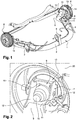
- a rear axle of such a vehicle schematically comprises a flexible tubular axle 1 and curved, making it possible to distinguish a central tubular segment 2 extending transversely in the vehicle and two side segments 3, 4 each terminating in a free end 5, said three segments 2, 3, 4 being in continuity with one another.
- the central segment 2 represents the most forward part of the axle 1 and has a connection point 6 to an element of the vehicle body, said connection point 6 allowing a rotational movement of said front segment 2, in particular to collect the stresses generated at the rear wheels 20 of the vehicle, in the case of a bend.
- an axle head yoke 7 is placed at each of the two free ends 5 of the axle 1, to connect a drum brake 8 to said axle 1.
- a yoke 8 comprises a central body 9 of small thickness consisting of a flat upper wall 10 and a flat lower wall 11, and two lateral arms 12 framing said central body 9.
- the two walls 10,11 are inclined relative to each other.
- Each side arm 12 is represented by a flat wall of small thickness, extending along said two walls 10, 11, said two arms 12 being mutually parallel.
- Each of said arms 12 has at one of its ends a rounded notch having a curvature identical to that of a free tubular end 5 of the axle 1.
- Each drum brake 8 comprises a fixed drum plate 13 and a movable part in rotation 14 which is secured to the wheel 20 and is called the drum. More precisely, the drum plate 13 has schematically the shape of a flat disc of small thickness, and is inserted between the upper wall 10 of the body 9 of the yoke 7 and a fixed part 30 of a bearing of the wheel 20. Said fixed part 30 of the bearing is fixed to said upper wall 10 of the body 9 of the yoke 7 by means of screws 21.
- Each of the two free ends 5 of the flexible axle 1 is placed and then fixed in the two rounded notches. of the two arms 12 of the yoke 7.
- the flexible axle 1, the two yokes 7, the two fixed parts 30 of the bearings and the two drum plates 13 constitute an overall part, which is rigid.
- a rectilinear and cylindrical transmission shaft 15 connects the two upper faces 10 of the two yokes 7 placed on either side of the flexible axle 1, in order to impart a rotational movement to the two rear wheels 20.
- this tree 15 has been artificially sectioned on the view of the figure 2 , to make it possible to show the arrangement of the various elements placed behind and next to said shaft 15.
- a wheel anti-lock system comprises two sensors 16 each intended to measure the speed of a driving rear wheel 20.
- Each sensor 16 is fixed in the drum plate 13 by means of a screw 17 passing through said plate 13 and the upper wall 10 of the central body 9 of the yoke 7.
- the sensor 16 has a sensitive end 18 opening out at the level of the part 19 the bearing of the wheel 20, which is rotatable. More precisely, this sensitive end 18 is oriented in such a way that it allows an axial reading of the wheel speed, at the level of a magnetic seal 22 of this part 19 of the bearing which is movable in rotation. The reading play between the sensitive end 18 of the sensor 16 and the magnetic seal is reduced and is between 1 mm and 0.1 mm.
Landscapes
- Engineering & Computer Science (AREA)
- Mechanical Engineering (AREA)
- General Engineering & Computer Science (AREA)
- Transportation (AREA)
- Regulating Braking Force (AREA)
Claims (9)
- Antiblockierbremssystem (20) für ein Fahrzeug, wobei das Fahrzeug eine flexible Hinterachse (1) umfasst, die dazu konfiguriert ist, eine Antriebsfunktion des Fahrzeugs zu übernehmen, wobei das System zwei Sensoren (16) umfasst, die jeweils dazu fähig sind, die Geschwindigkeit eines der zwei Räder (20), die mit der Achse (1) verbunden sind, zu messen, dadurch gekennzeichnet, dass jeder Sensor (16) an einem festen Bremsträger (13) befestigt ist, wobei der Träger (13) fest mit der Achse (1) verbunden ist und den festen Teil einer Trommelbremse jedes der zwei Räder (20) bildet, wobei jeder Bremsträger (13) mittels eines Achsengabelkopfes (7) und eines festen Teils (30) eines Lagers eines Rades (20) fest mit der Achse (1, 5) verbunden ist.
- Antiblockiersystem nach Anspruch 1, dadurch gekennzeichnet, dass jeder Bremsträger (13) zwischen dem Achsengabelkopf (7) und dem festen Teil (30) des Lagers eingefügt ist und dass der feste Teil (30) des Lagers durch Verschrauben an dem Gabelkopf (7) befestigt ist.
- Antiblockiersystem nach Anspruch 2, dadurch gekennzeichnet, dass jeder Sensor (16) mit Hilfe einer Befestigungsschraube (17) an dem Bremsträger (13) befestigt ist.
- Antiblockiersystem nach Anspruch 3, dadurch gekennzeichnet, dass jede Befestigungsschraube (17) durch den Bremsträger (13) und eine Wand (10) des Gabelkopfes (7), an der der Träger (13) anliegt, hindurchgeht.
- Antiblockiersystem nach Anspruch 4, dadurch gekennzeichnet, dass das Fahrzeug eine Antriebswelle (15) besitzt, von der jedes Ende in der Wand (10) jedes der zwei Achsengabelköpfe (7) eingesetzt ist, und dass jede Befestigungsschraube (17) des Sensors (16) durch die Wand (10) hindurchgeht und dabei mit Abstand zu dem Ende positioniert ist.
- Antiblockiersystem nach einem der Ansprüche 1 bis 5, dadurch gekennzeichnet, dass jeder Gabelkopf (7) zwei Arme (13) beinhaltet, die dazu bestimmt sind, die Achse (1, 5) zu halten.
- Antiblockiersystem nach einem der Ansprüche 1 bis 6, dadurch gekennzeichnet, dass jeder Sensor (16) die Geschwindigkeit eines Rades (20) im Bereich eines mobilen Teils (19) eines Lagers des Rades (20) misst.
- Antiblockiersystem nach Anspruch 7, dadurch gekennzeichnet, dass mindestens einer der Sensoren (16) so ausgerichtet ist, dass er eine axiale Ablesung der Radgeschwindigkeit gestattet.
- Antiblockiersystem nach einem der Ansprüche 1 bis 8, dadurch gekennzeichnet, dass die Achse (1) einen einzigen Punkt zur Befestigung (6) an einem Element des Fahrzeugaufbaus besitzt, wobei der Punkt (6) eine Drehbewegung der Achse (1) zulässt.
Applications Claiming Priority (2)
| Application Number | Priority Date | Filing Date | Title |
|---|---|---|---|
| FR1454331A FR3021016B1 (fr) | 2014-05-15 | 2014-05-15 | Systeme d'antiblocage des roues d'un vehicule |
| PCT/FR2015/051229 WO2015173502A1 (fr) | 2014-05-15 | 2015-05-11 | Systeme d 'antiblocage des roues d'un vehicule |
Publications (2)
| Publication Number | Publication Date |
|---|---|
| EP3142873A1 EP3142873A1 (de) | 2017-03-22 |
| EP3142873B1 true EP3142873B1 (de) | 2021-10-13 |
Family
ID=51168210
Family Applications (1)
| Application Number | Title | Priority Date | Filing Date |
|---|---|---|---|
| EP15725843.5A Not-in-force EP3142873B1 (de) | 2014-05-15 | 2015-05-11 | Antiblockierbremssystem für ein fahrzeug |
Country Status (3)
| Country | Link |
|---|---|
| EP (1) | EP3142873B1 (de) |
| FR (1) | FR3021016B1 (de) |
| WO (1) | WO2015173502A1 (de) |
Families Citing this family (1)
| Publication number | Priority date | Publication date | Assignee | Title |
|---|---|---|---|---|
| CN109572662B (zh) * | 2018-12-29 | 2021-06-29 | 奇瑞汽车股份有限公司 | 一种用于abs安装的安装支架 |
Family Cites Families (3)
| Publication number | Priority date | Publication date | Assignee | Title |
|---|---|---|---|---|
| DE19622954C2 (de) * | 1996-06-07 | 2000-08-10 | Porsche Ag | Radaufhängung für ein Kraftfahrzeug |
| GB2324869A (en) * | 1997-04-30 | 1998-11-04 | Nissan Europ Tech Centre | Drum brake with speed sensor |
| EP1518769B1 (de) * | 2002-07-02 | 2010-04-28 | JTEKT Corporation | Fahrzeugsteuerungssystem |
-
2014
- 2014-05-15 FR FR1454331A patent/FR3021016B1/fr not_active Expired - Fee Related
-
2015
- 2015-05-11 WO PCT/FR2015/051229 patent/WO2015173502A1/fr not_active Ceased
- 2015-05-11 EP EP15725843.5A patent/EP3142873B1/de not_active Not-in-force
Also Published As
| Publication number | Publication date |
|---|---|
| WO2015173502A1 (fr) | 2015-11-19 |
| FR3021016A1 (fr) | 2015-11-20 |
| EP3142873A1 (de) | 2017-03-22 |
| FR3021016B1 (fr) | 2016-05-13 |
Similar Documents
| Publication | Publication Date | Title |
|---|---|---|
| CA2547876C (fr) | Cellule de mesure d'effort et axe de liaison equipe d'une telle cellule | |
| EP1549910B1 (de) | Positionssensor mit variabler reluktanz | |
| EP2299252A1 (de) | Vorrichtung an Bord eines Fahrrads zur Messung von Kräfte und Fahrrad mit einer derartigen Vorrichtung | |
| EP1533600A1 (de) | Gebersystem zur absoluten Messung eines Drillmoments und Modul mit einem solchen System | |
| EP0376795B1 (de) | Ausdehnungsmesssonde zur Messung der Belastung für ein Bohrelement | |
| EP0474562B1 (de) | Rotierende Kodierhülse für Abtastvorrichtung | |
| FR3062636A1 (fr) | Atterrisseur d'aeronef | |
| EP4182652B1 (de) | Fahrradantrieb mit drehmomentsensor | |
| EP3142873B1 (de) | Antiblockierbremssystem für ein fahrzeug | |
| EP3175136B1 (de) | Fahrzeugbremsenbetätiger | |
| FR2973292A1 (fr) | Train de vehicule comportant un palier et palier correspondant | |
| CA2983187A1 (fr) | Couplemetre a mesure de deformation | |
| FR3124856A1 (fr) | Capteur d’usure de garniture de frein | |
| EP3428055B1 (de) | Verfahren und vorrichtung zur bestimmung der richtung und amplitude einer angelegten kraft auf eine antriebsgondel für ein boot | |
| WO2020115581A1 (fr) | Système de fixation pour boitier de mesure de caractéristiques de pneumatique | |
| FR3031722A1 (fr) | Dispositif de determination du couple applique a un axe de pedalier | |
| EP1983309A1 (de) | Instrumentengesteuertes Gelenksystem | |
| EP4414677A1 (de) | System zur bestimmung eines zwischen zwei rotierenden teilen ausgeübten drehmoments | |
| EP3724604B1 (de) | Verbesserte trägheitseinheit mit aufgehängter trägheitsvorrichtung | |
| FR3122710A1 (fr) | Unité d’étrier de frein à système à détecteur d’usure et procédé de relevé d’usure de garnitures de frein et de disque de frein d’une unité d’étrier d’un frein à disque | |
| FR2879990A1 (fr) | Systeme d'actionnement d'arbre de direction instrumente comprenant un centre fixe | |
| EP1245959A1 (de) | Wälzlageranordnung mit Messaufnehmer | |
| FR2940436A1 (fr) | Dispositif d'etalonnage d'appareils de mesure de contraintes | |
| FR3071601A1 (fr) | Dispositif de mesure d'epaisseur d'un disque de frein | |
| FR3156423A1 (fr) | Module mécatronique d’assistance électrique |
Legal Events
| Date | Code | Title | Description |
|---|---|---|---|
| STAA | Information on the status of an ep patent application or granted ep patent |
Free format text: STATUS: THE INTERNATIONAL PUBLICATION HAS BEEN MADE |
|
| PUAI | Public reference made under article 153(3) epc to a published international application that has entered the european phase |
Free format text: ORIGINAL CODE: 0009012 |
|
| STAA | Information on the status of an ep patent application or granted ep patent |
Free format text: STATUS: REQUEST FOR EXAMINATION WAS MADE |
|
| 17P | Request for examination filed |
Effective date: 20161121 |
|
| AK | Designated contracting states |
Kind code of ref document: A1 Designated state(s): AL AT BE BG CH CY CZ DE DK EE ES FI FR GB GR HR HU IE IS IT LI LT LU LV MC MK MT NL NO PL PT RO RS SE SI SK SM TR |
|
| AX | Request for extension of the european patent |
Extension state: BA ME |
|
| DAV | Request for validation of the european patent (deleted) | ||
| DAX | Request for extension of the european patent (deleted) | ||
| GRAP | Despatch of communication of intention to grant a patent |
Free format text: ORIGINAL CODE: EPIDOSNIGR1 |
|
| STAA | Information on the status of an ep patent application or granted ep patent |
Free format text: STATUS: GRANT OF PATENT IS INTENDED |
|
| INTG | Intention to grant announced |
Effective date: 20210514 |
|
| RIN1 | Information on inventor provided before grant (corrected) |
Inventor name: WILLEMENOT, JOHANN Inventor name: FOUREST, JEAN BAPTISTE Inventor name: TERROITIN, ALAN |
|
| GRAS | Grant fee paid |
Free format text: ORIGINAL CODE: EPIDOSNIGR3 |
|
| GRAA | (expected) grant |
Free format text: ORIGINAL CODE: 0009210 |
|
| STAA | Information on the status of an ep patent application or granted ep patent |
Free format text: STATUS: THE PATENT HAS BEEN GRANTED |
|
| AK | Designated contracting states |
Kind code of ref document: B1 Designated state(s): AL AT BE BG CH CY CZ DE DK EE ES FI FR GB GR HR HU IE IS IT LI LT LU LV MC MK MT NL NO PL PT RO RS SE SI SK SM TR |
|
| REG | Reference to a national code |
Ref country code: GB Ref legal event code: FG4D Free format text: NOT ENGLISH |
|
| REG | Reference to a national code |
Ref country code: CH Ref legal event code: EP |
|
| REG | Reference to a national code |
Ref country code: DE Ref legal event code: R096 Ref document number: 602015074085 Country of ref document: DE |
|
| REG | Reference to a national code |
Ref country code: IE Ref legal event code: FG4D Free format text: LANGUAGE OF EP DOCUMENT: FRENCH |
|
| REG | Reference to a national code |
Ref country code: AT Ref legal event code: REF Ref document number: 1437926 Country of ref document: AT Kind code of ref document: T Effective date: 20211115 |
|
| REG | Reference to a national code |
Ref country code: LT Ref legal event code: MG9D |
|
| REG | Reference to a national code |
Ref country code: NL Ref legal event code: MP Effective date: 20211013 |
|
| RAP4 | Party data changed (patent owner data changed or rights of a patent transferred) |
Owner name: RENAULT S.A.S |
|
| REG | Reference to a national code |
Ref country code: AT Ref legal event code: MK05 Ref document number: 1437926 Country of ref document: AT Kind code of ref document: T Effective date: 20211013 |
|
| PG25 | Lapsed in a contracting state [announced via postgrant information from national office to epo] |
Ref country code: RS Free format text: LAPSE BECAUSE OF FAILURE TO SUBMIT A TRANSLATION OF THE DESCRIPTION OR TO PAY THE FEE WITHIN THE PRESCRIBED TIME-LIMIT Effective date: 20211013 Ref country code: LT Free format text: LAPSE BECAUSE OF FAILURE TO SUBMIT A TRANSLATION OF THE DESCRIPTION OR TO PAY THE FEE WITHIN THE PRESCRIBED TIME-LIMIT Effective date: 20211013 Ref country code: FI Free format text: LAPSE BECAUSE OF FAILURE TO SUBMIT A TRANSLATION OF THE DESCRIPTION OR TO PAY THE FEE WITHIN THE PRESCRIBED TIME-LIMIT Effective date: 20211013 Ref country code: BG Free format text: LAPSE BECAUSE OF FAILURE TO SUBMIT A TRANSLATION OF THE DESCRIPTION OR TO PAY THE FEE WITHIN THE PRESCRIBED TIME-LIMIT Effective date: 20220113 Ref country code: AT Free format text: LAPSE BECAUSE OF FAILURE TO SUBMIT A TRANSLATION OF THE DESCRIPTION OR TO PAY THE FEE WITHIN THE PRESCRIBED TIME-LIMIT Effective date: 20211013 |
|
| PG25 | Lapsed in a contracting state [announced via postgrant information from national office to epo] |
Ref country code: IS Free format text: LAPSE BECAUSE OF FAILURE TO SUBMIT A TRANSLATION OF THE DESCRIPTION OR TO PAY THE FEE WITHIN THE PRESCRIBED TIME-LIMIT Effective date: 20220213 Ref country code: SE Free format text: LAPSE BECAUSE OF FAILURE TO SUBMIT A TRANSLATION OF THE DESCRIPTION OR TO PAY THE FEE WITHIN THE PRESCRIBED TIME-LIMIT Effective date: 20211013 Ref country code: PT Free format text: LAPSE BECAUSE OF FAILURE TO SUBMIT A TRANSLATION OF THE DESCRIPTION OR TO PAY THE FEE WITHIN THE PRESCRIBED TIME-LIMIT Effective date: 20220214 Ref country code: PL Free format text: LAPSE BECAUSE OF FAILURE TO SUBMIT A TRANSLATION OF THE DESCRIPTION OR TO PAY THE FEE WITHIN THE PRESCRIBED TIME-LIMIT Effective date: 20211013 Ref country code: NO Free format text: LAPSE BECAUSE OF FAILURE TO SUBMIT A TRANSLATION OF THE DESCRIPTION OR TO PAY THE FEE WITHIN THE PRESCRIBED TIME-LIMIT Effective date: 20220113 Ref country code: NL Free format text: LAPSE BECAUSE OF FAILURE TO SUBMIT A TRANSLATION OF THE DESCRIPTION OR TO PAY THE FEE WITHIN THE PRESCRIBED TIME-LIMIT Effective date: 20211013 Ref country code: LV Free format text: LAPSE BECAUSE OF FAILURE TO SUBMIT A TRANSLATION OF THE DESCRIPTION OR TO PAY THE FEE WITHIN THE PRESCRIBED TIME-LIMIT Effective date: 20211013 Ref country code: HR Free format text: LAPSE BECAUSE OF FAILURE TO SUBMIT A TRANSLATION OF THE DESCRIPTION OR TO PAY THE FEE WITHIN THE PRESCRIBED TIME-LIMIT Effective date: 20211013 Ref country code: GR Free format text: LAPSE BECAUSE OF FAILURE TO SUBMIT A TRANSLATION OF THE DESCRIPTION OR TO PAY THE FEE WITHIN THE PRESCRIBED TIME-LIMIT Effective date: 20220114 Ref country code: ES Free format text: LAPSE BECAUSE OF FAILURE TO SUBMIT A TRANSLATION OF THE DESCRIPTION OR TO PAY THE FEE WITHIN THE PRESCRIBED TIME-LIMIT Effective date: 20211013 |
|
| REG | Reference to a national code |
Ref country code: DE Ref legal event code: R097 Ref document number: 602015074085 Country of ref document: DE |
|
| RAP4 | Party data changed (patent owner data changed or rights of a patent transferred) |
Owner name: RENAULT S.A.S |
|
| PG25 | Lapsed in a contracting state [announced via postgrant information from national office to epo] |
Ref country code: SM Free format text: LAPSE BECAUSE OF FAILURE TO SUBMIT A TRANSLATION OF THE DESCRIPTION OR TO PAY THE FEE WITHIN THE PRESCRIBED TIME-LIMIT Effective date: 20211013 Ref country code: SK Free format text: LAPSE BECAUSE OF FAILURE TO SUBMIT A TRANSLATION OF THE DESCRIPTION OR TO PAY THE FEE WITHIN THE PRESCRIBED TIME-LIMIT Effective date: 20211013 Ref country code: RO Free format text: LAPSE BECAUSE OF FAILURE TO SUBMIT A TRANSLATION OF THE DESCRIPTION OR TO PAY THE FEE WITHIN THE PRESCRIBED TIME-LIMIT Effective date: 20211013 Ref country code: EE Free format text: LAPSE BECAUSE OF FAILURE TO SUBMIT A TRANSLATION OF THE DESCRIPTION OR TO PAY THE FEE WITHIN THE PRESCRIBED TIME-LIMIT Effective date: 20211013 Ref country code: DK Free format text: LAPSE BECAUSE OF FAILURE TO SUBMIT A TRANSLATION OF THE DESCRIPTION OR TO PAY THE FEE WITHIN THE PRESCRIBED TIME-LIMIT Effective date: 20211013 Ref country code: CZ Free format text: LAPSE BECAUSE OF FAILURE TO SUBMIT A TRANSLATION OF THE DESCRIPTION OR TO PAY THE FEE WITHIN THE PRESCRIBED TIME-LIMIT Effective date: 20211013 |
|
| PLBE | No opposition filed within time limit |
Free format text: ORIGINAL CODE: 0009261 |
|
| STAA | Information on the status of an ep patent application or granted ep patent |
Free format text: STATUS: NO OPPOSITION FILED WITHIN TIME LIMIT |
|
| 26N | No opposition filed |
Effective date: 20220714 |
|
| PG25 | Lapsed in a contracting state [announced via postgrant information from national office to epo] |
Ref country code: AL Free format text: LAPSE BECAUSE OF FAILURE TO SUBMIT A TRANSLATION OF THE DESCRIPTION OR TO PAY THE FEE WITHIN THE PRESCRIBED TIME-LIMIT Effective date: 20211013 |
|
| PG25 | Lapsed in a contracting state [announced via postgrant information from national office to epo] |
Ref country code: SI Free format text: LAPSE BECAUSE OF FAILURE TO SUBMIT A TRANSLATION OF THE DESCRIPTION OR TO PAY THE FEE WITHIN THE PRESCRIBED TIME-LIMIT Effective date: 20211013 |
|
| REG | Reference to a national code |
Ref country code: CH Ref legal event code: PL |
|
| REG | Reference to a national code |
Ref country code: BE Ref legal event code: MM Effective date: 20220531 |
|
| PG25 | Lapsed in a contracting state [announced via postgrant information from national office to epo] |
Ref country code: MC Free format text: LAPSE BECAUSE OF FAILURE TO SUBMIT A TRANSLATION OF THE DESCRIPTION OR TO PAY THE FEE WITHIN THE PRESCRIBED TIME-LIMIT Effective date: 20211013 Ref country code: LU Free format text: LAPSE BECAUSE OF NON-PAYMENT OF DUE FEES Effective date: 20220511 Ref country code: LI Free format text: LAPSE BECAUSE OF NON-PAYMENT OF DUE FEES Effective date: 20220531 Ref country code: CH Free format text: LAPSE BECAUSE OF NON-PAYMENT OF DUE FEES Effective date: 20220531 |
|
| PG25 | Lapsed in a contracting state [announced via postgrant information from national office to epo] |
Ref country code: IE Free format text: LAPSE BECAUSE OF NON-PAYMENT OF DUE FEES Effective date: 20220511 |
|
| PG25 | Lapsed in a contracting state [announced via postgrant information from national office to epo] |
Ref country code: IT Free format text: LAPSE BECAUSE OF FAILURE TO SUBMIT A TRANSLATION OF THE DESCRIPTION OR TO PAY THE FEE WITHIN THE PRESCRIBED TIME-LIMIT Effective date: 20211013 Ref country code: BE Free format text: LAPSE BECAUSE OF NON-PAYMENT OF DUE FEES Effective date: 20220531 |
|
| P01 | Opt-out of the competence of the unified patent court (upc) registered |
Effective date: 20230608 |
|
| PGFP | Annual fee paid to national office [announced via postgrant information from national office to epo] |
Ref country code: DE Payment date: 20230519 Year of fee payment: 9 |
|
| PG25 | Lapsed in a contracting state [announced via postgrant information from national office to epo] |
Ref country code: HU Free format text: LAPSE BECAUSE OF FAILURE TO SUBMIT A TRANSLATION OF THE DESCRIPTION OR TO PAY THE FEE WITHIN THE PRESCRIBED TIME-LIMIT; INVALID AB INITIO Effective date: 20150511 |
|
| PG25 | Lapsed in a contracting state [announced via postgrant information from national office to epo] |
Ref country code: MK Free format text: LAPSE BECAUSE OF FAILURE TO SUBMIT A TRANSLATION OF THE DESCRIPTION OR TO PAY THE FEE WITHIN THE PRESCRIBED TIME-LIMIT Effective date: 20211013 Ref country code: CY Free format text: LAPSE BECAUSE OF FAILURE TO SUBMIT A TRANSLATION OF THE DESCRIPTION OR TO PAY THE FEE WITHIN THE PRESCRIBED TIME-LIMIT Effective date: 20211013 |
|
| PGFP | Annual fee paid to national office [announced via postgrant information from national office to epo] |
Ref country code: GB Payment date: 20240521 Year of fee payment: 10 |
|
| PGFP | Annual fee paid to national office [announced via postgrant information from national office to epo] |
Ref country code: FR Payment date: 20240528 Year of fee payment: 10 |
|
| PG25 | Lapsed in a contracting state [announced via postgrant information from national office to epo] |
Ref country code: MT Free format text: LAPSE BECAUSE OF FAILURE TO SUBMIT A TRANSLATION OF THE DESCRIPTION OR TO PAY THE FEE WITHIN THE PRESCRIBED TIME-LIMIT Effective date: 20211013 |
|
| REG | Reference to a national code |
Ref country code: DE Ref legal event code: R119 Ref document number: 602015074085 Country of ref document: DE |
|
| PG25 | Lapsed in a contracting state [announced via postgrant information from national office to epo] |
Ref country code: TR Free format text: LAPSE BECAUSE OF FAILURE TO SUBMIT A TRANSLATION OF THE DESCRIPTION OR TO PAY THE FEE WITHIN THE PRESCRIBED TIME-LIMIT Effective date: 20211013 |
|
| GBPC | Gb: european patent ceased through non-payment of renewal fee |
Effective date: 20250511 |
|
| PG25 | Lapsed in a contracting state [announced via postgrant information from national office to epo] |
Ref country code: GB Free format text: LAPSE BECAUSE OF NON-PAYMENT OF DUE FEES Effective date: 20250511 |
|
| PG25 | Lapsed in a contracting state [announced via postgrant information from national office to epo] |
Ref country code: DE Free format text: LAPSE BECAUSE OF NON-PAYMENT OF DUE FEES Effective date: 20251202 |
|
| PG25 | Lapsed in a contracting state [announced via postgrant information from national office to epo] |
Ref country code: FR Free format text: LAPSE BECAUSE OF NON-PAYMENT OF DUE FEES Effective date: 20250531 |