EP3143253B1 - Outil de fond de trou - Google Patents
Outil de fond de trou Download PDFInfo
- Publication number
- EP3143253B1 EP3143253B1 EP15793502.4A EP15793502A EP3143253B1 EP 3143253 B1 EP3143253 B1 EP 3143253B1 EP 15793502 A EP15793502 A EP 15793502A EP 3143253 B1 EP3143253 B1 EP 3143253B1
- Authority
- EP
- European Patent Office
- Prior art keywords
- piston
- passages
- fluid
- tool
- housing
- Prior art date
- Legal status (The legal status is an assumption and is not a legal conclusion. Google has not performed a legal analysis and makes no representation as to the accuracy of the status listed.)
- Active
Links
Images


Classifications
-
- E—FIXED CONSTRUCTIONS
- E21—EARTH OR ROCK DRILLING; MINING
- E21B—EARTH OR ROCK DRILLING; OBTAINING OIL, GAS, WATER, SOLUBLE OR MELTABLE MATERIALS OR A SLURRY OF MINERALS FROM WELLS
- E21B47/00—Survey of boreholes or wells
- E21B47/002—Survey of boreholes or wells by visual inspection
-
- E—FIXED CONSTRUCTIONS
- E21—EARTH OR ROCK DRILLING; MINING
- E21B—EARTH OR ROCK DRILLING; OBTAINING OIL, GAS, WATER, SOLUBLE OR MELTABLE MATERIALS OR A SLURRY OF MINERALS FROM WELLS
- E21B21/00—Methods or apparatus for flushing boreholes, e.g. by use of exhaust air from motor
- E21B21/08—Controlling or monitoring pressure or flow of drilling fluid, e.g. automatic filling of boreholes, automatic control of bottom pressure
-
- E—FIXED CONSTRUCTIONS
- E21—EARTH OR ROCK DRILLING; MINING
- E21B—EARTH OR ROCK DRILLING; OBTAINING OIL, GAS, WATER, SOLUBLE OR MELTABLE MATERIALS OR A SLURRY OF MINERALS FROM WELLS
- E21B27/00—Containers for collecting or depositing substances in boreholes or wells, e.g. bailers, baskets or buckets for collecting mud or sand; Drill bits with means for collecting substances, e.g. valve drill bits
-
- E—FIXED CONSTRUCTIONS
- E21—EARTH OR ROCK DRILLING; MINING
- E21B—EARTH OR ROCK DRILLING; OBTAINING OIL, GAS, WATER, SOLUBLE OR MELTABLE MATERIALS OR A SLURRY OF MINERALS FROM WELLS
- E21B34/00—Valve arrangements for boreholes or wells
- E21B34/06—Valve arrangements for boreholes or wells in wells
- E21B34/14—Valve arrangements for boreholes or wells in wells operated by movement of tools, e.g. sleeve valves operated by pistons or wire line tools
-
- E—FIXED CONSTRUCTIONS
- E21—EARTH OR ROCK DRILLING; MINING
- E21B—EARTH OR ROCK DRILLING; OBTAINING OIL, GAS, WATER, SOLUBLE OR MELTABLE MATERIALS OR A SLURRY OF MINERALS FROM WELLS
- E21B37/00—Methods or apparatus for cleaning boreholes or wells
-
- E—FIXED CONSTRUCTIONS
- E21—EARTH OR ROCK DRILLING; MINING
- E21B—EARTH OR ROCK DRILLING; OBTAINING OIL, GAS, WATER, SOLUBLE OR MELTABLE MATERIALS OR A SLURRY OF MINERALS FROM WELLS
- E21B47/00—Survey of boreholes or wells
- E21B47/01—Devices for supporting measuring instruments on drill bits, pipes, rods or wirelines; Protecting measuring instruments in boreholes against heat, shock, pressure or the like
- E21B47/017—Protecting measuring instruments
Definitions
- the present invention relates to survey tools for boreholes.
- the invention has been devised particularly, although not necessarily solely, in relation to tools for surveying wells and, in particular, to downhole survey tools including cleaning tools and cameras.
- Blowouts of wells may lead to catastrophic events.
- An example of such an event is the British Petroleum's environmental catastrophe that occurred in 20 April 2010.
- a well blowout is an uncontrolled release of hydrocarbons from a well. Typically, blowouts occur after a failure of the pressure control systems contained in the well.
- BOP Blowout preventers
- the BOP includes shears and packing seals that may be caked with debris such as mud, cement or metallic residue. This may render the BOP inoperative. Regular inspection and cleaning of these seals is essential to ensure proper functioning of the BOP.
- the routine testing includes a visual inspection of the equipment included in the well and, in particular, of the BOP.
- One of the reasons that visual inspection is undertaken is to be able to visualise the location and configuration of the debris. Visualising the location of the debris and its configuration permits applying a cleaning process at the particular location where the debris is located. This makes the cleaning process more efficient.
- a particular disadvantage of conventional survey tools is that the inspection and cleaning process using these conventional tools is cumbersome and time consuming. This is particularly true because the process requires use a multitude of drill string tools that need to deployed into the well separately.
- a jet cleaning tool is deployed into the riser. This tool cleans the interior of the well and in particular the BOP. After completion of this particular cleaning process, the jet cleaning tool is removed from the well and a conventional downhole camera is inserted into the well for inspection of the interior of the well and its equipment.
- European patent publication 1867833 describes an apparatus for obtaining images of the wall of a borehole, comprises a tool (12) body; a light source (26) mounted on the tool body and arranged to illuminate the borehole wall; a camera (22) mounted in the tool body; and a mirror (28) moveably mounted on the tool body and spaced axially from the camera and arranged to reflect an image of the borehole wall at the camera, wherein movement of the mirror allows images of different parts of the borehole wall to be reflected at the camera.
- US 2912495A discloses an apparatus for visually observing the condition of well bores and is particularly concerned with a device of this character embodying a closed circuit television system for viewing from a remote distance the inside of an oil Well bore or casing.
- WO9957416A1 discloses a rotary jet cleaning apparatus suitable for use in cleaning pipes and/or boreholes.
- the apparatus comprises a positive displacement motor (22) and a rotary jetting tool (23) drivingly connected (24) to an output drive part (25) of said motor.
- the motor has a drive fluid supply conduit (30), and the rotary jetting tool (23) has at least one generally radially outwardly directed nozzle means (43) provided with a jetting fluid supply conduit (29).
- the jetting fluid supply conduit (29) and drive fluid supply conduit (30) are connected in parallel to a common fluid supply inlet means (40) to said apparatus so that jetting fluid may be supplied to said jetting tool nozzle means substantially without reduction in pressure due to running of the motor for rotation of said jetting tool.
- US4442899A discloses a method and system for cleaning well liners employing a non-rotating tubing string attached to a hydraulic jet carrier assembly.
- the assembly has a plurality of jet nozzles spaced along its length, each of said nozzles expelling a stream of fluid under pressure against the liner with a force which has an equal and opposite reactive force.
- the nozzles are oriented along the carrier such that the reactive force for each jet is directionally offset with respect to the central axis of the carrier, thereby creating a twisting moment tending to rotate the carrier about its central axis.
- the bottom hole differential pressure of the fluid supplied to the jet carrier is varied to rotationally oscillate the carrier as it is moved vertically within the well bore to increase the coverage of the fluid streams on the liner.
- the present disclosure provides a tool for cleaning a camera, inner surfaces of a borehole to be inspected, and/or a BOP inner surface of a well as detailed in claim 1.
- Advantageous features are provided in dependent claims.
- a survey tool for attachment to a drill string for inserting the survey tool into a borehole, the survey tool comprising a body having a proximal end adapted to receive fluid from the drill string and a distal end for receiving survey equipment, a wall having an inner surface defining a first bore within the body and an exterior surface defining at least a portion of the exterior of the body, and a piston adapted to be displaced within the first bore, the wall comprising a plurality of passages extending between the bore and the exterior surface to allow communication between the exterior of the body and the first bore; wherein the piston is adapted to be selectively displaced between a first condition to permit the fluid to flow through at least one first passage of the plurality of passages for delivery of the fluid to a first location of the borehole and a second condition to permit the fluid to flow through at least one second passage of the plurality of passages for delivery of the fluid to a second location of the borehole.
- the first location of the borehole comprises an area of the borehole adjacent the wall of the survey tool.
- the second location of the borehole comprises an area of the borehole to be surveyed by the survey equipment.
- the piston is adapted to be selectively displaced to a third location to permit the fluid to flow through at least one third passage of the plurality of passages for delivery of the fluid to the distal end of the body of the survey tool.
- the piston comprises a second bore for receiving the fluid from the drill string.
- the piston is adapted to move along the longitudinal axis of the first bore between the first condition and the second condition.
- the piston is adapted to move along the longitudinal axis of the first bore between the first condition, the second condition and the third condition
- the piston comprises a plurality of fourth passages allowing the fluid to flow, respectively, from the second bore to any one of the at least one first, second or third passages of the wall of the survey tool during movement of the piston between the first, second and third conditions.
- the piston is adapted to be selectively moved along the longitudinal axis of the first bore between the first condition, the second condition and the third condition.
- the piston is adapted to be selectively rotated around the longitudinal axis of the first bore between the first condition, the second condition and the third condition.
- the at least one first passage comprises high volume passages.
- the at least one second passage comprises high pressure jetting passages.
- the at least one third passage comprises front jetting passages.
- the piston when in the first location, allows fluid exiting the housing through the high volume passages but blocks fluid from flowing through the front jetting passages and through the high pressure jetting passages.
- the piston when in the second location, allows fluid exiting the housing through the high pressure jetting passages but blocks fluid from flowing through the high volume passages and through the front jetting passages.
- the piston when in the third location, allows fluid exiting the housing through the front jetting passages but blocks fluid from flowing through the high volume passages and through the high pressure jetting passages.
- the piston is operatively connected to at least one actuator for movement of the piston along the longitudinal axis of the body of the survey tool.
- the actuator comprises a piston chamber, the piston chamber having a lower chamber and an upper chamber, the lower and upper chamber being fluidly connected for selectively displacing the piston along the longitudinal axis of the body of the survey tool
- the actuator comprises an electric motor comprising a spindle drive worm shaft operatively connected to the piston for movement of the piston along the longitudinal axis of the body of the survey tool.
- the actuator comprises an electric motor operatively connected to a distal end of the piston for selectively rotating the piston along the longitudinal axis of the body of the survey tool.
- the survey tool further comprises an outer sleeve comprising outlets being fluidly communicated with the plurality of passages of the body allowing passage of the fluid through the outlets of the outer sleeve.
- the high pressure jetting passages comprises high pressure filter nozzles for filtering of the fluid.
- the survey equipment comprises a camera.
- the survey tool further comprises an electric energy source adapted to be electrically connected to electric motors and the survey equipment.
- the energy source comprises a battery adapted to be received by the body of the survey tool.
- a survey tool for attachment to a drill string for inserting the survey tool into a borehole, the survey tool comprising a housing having a proximal end adapted for attachment to the drill string and a bore traversing the housing adapted to receive fluid from the drill string, and a piston adapted to be received within the bore, the piston being adapted to be selectively displaced between at least a first condition and a second condition, wherein in the first condition the fluid exits the housing at a first location and in the second condition the fluid exits the housing at a second location.
- the piston is adapted to be displaced selectively between the first condition, the second condition and a further third condition.
- the first location comprising sides of the housing permitting fluid to exit the housing for pressure jetting of side walls of the borehole or equipment contained in the borehole.
- the second location comprises a location at a distal end of the housing.
- the distal end of the housing is adapted to receive a camera.
- the second location is adjacent the distal end for delivering the fluid to the camera for cleaning and/or cooling thereof.
- the housing comprises a plurality of set of openings to allow fluid to exit the housing.
- the housing comprises a first set of high pressure jetting passages, the passages traversing the sides of the housing to allow pressure jetting of the side walls of the borehole or equipment contained in the borehole.
- the housing comprises a second set of front jetting passages, the passages traversing the distal end of the housing to allow cleaning and/or cooling of the camera.
- the housing comprises a third set of high volume passages, the passages traversing the housing to allow flushing of the borehole.
- the piston when in the first location allows fluid exiting the housing through the high pressure jetting passages, and the piston blocks fluid from flowing through the front jetting passages and through the high volume passages.
- the piston when in the second location allows fluid exiting the housing through the front jetting passages, and the piston blocks fluid from flowing through the high volume passages and through the high pressure jetting passages.
- the piston when in the third location allows fluid exiting the housing through the high volume passages, and the piston blocks fluid from flowing through the front jetting passages and through the high pressure jetting passages.
- the housing and the piston is adapted to define a pressure chamber within the bore of the housing for containment of the fluid of the drill string.
- the pressure chamber comprises an upper pressure chamber, the upper pressure chamber being defined when the piston is located in the first location.
- the pressure chamber further comprises an lower pressure chamber, the lower pressure chamber being defined when the piston is located in the second and third locations.
- the piston is operatively connected to at least one actuator for movement of the piston along the longitudinal axis of the housing.
- the actuator comprises an electric motor comprising a spindle drive worm shaft operatively connected to the piston for movement of the piston along the longitudinal axis of the housing.
- the actuator comprises an upper and lower chamber adapted to move the piston, the upper and lower chamber being adapted to selectively receive hydraulic fluid for movement of the piston, the upper chamber receiving hydraulic fluid for moving of the piston to the distal end of the housing, and the lower chamber receiving hydraulic fluid for moving the piston to the proximal end of the housing.
- the hydraulic fluid is driven by a hydraulic pump fluidly connected to the upper and lower chamber, the pump driven by an electric motor.
- the electric motor and the hydraulic pump are located inside the piston.
- the electric motor and the hydraulic pump are located on the drill string.
- the actuator comprises an electric motor operatively connected to a distal end of the piston for selectively moving the piston along the longitudinal axis of the housing between the first, second and third locations.
- the actuator comprises an electric motor operatively connected to a distal end of the piston for selectively rotating the piston along the longitudinal axis of the housing between the first, second and third locations.
- the piston comprises a bore for receiving the fluid.
- the piston comprises a plurality of openings to allow fluid to exit the housing when the piston are located in either the first, second and fourth conditions.
- the first set of opening are located on the piston at first locations such the first set of openings fluidly communicate with the high pressure jetting passages of the housing when the piston is located in the first location.
- the second set of openings are located on the piston at second locations such that the second set of openings fluidly communicate with the front jetting passages of the housing when the piston is located in the second location.
- the third set of openings are located on the piston at third locations such that the third set of openings fluidly communicate with the high volume passages of the housing when the piston is located in the third location.
- the survey tool further comprises an outer sleeve comprising outlets being fluidly communicated with the plurality of set of passages of the housing to allow passage of the fluid through the outlets of the outer sleeve.
- the first set of high pressure jetting passages comprises high pressure filter nozzles for filtering of the fluid.
- the survey tool further comprising electric energy source adapted to being electrically connected to an electric motor and a camera.
- the energy source comprises a battery adapted to be received by the housing.
- the proximal end of the housing comprises a one way flip flap valve.
- the proximal end of the housing comprises a one way flap pup.
- the distal end of the housing comprises a basket adapted to collect debris.
- a drill string comprising a survey tool in accordance with any one the preceding claims.
- paragraph [0113] of the description of the specification includes a listing of the reference number shown in the figures 1 to 7 indicating the name of the parts of the survey tool labelled by the listed reference numbers.
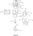
- Figure 1 is a schematic view of a survey tool 1 in accordance with the first embodiment of the invention.
- the survey tool 1 is adapted to be mounted on a drill string for deployment of the survey tool into a borehole such as a well.
- the survey tool 1 shown in the figures comprises a camera and a cleaning tool.
- the camera 14 is adapted to provide a real-time viewing with 360 degree continuous rotation with 110 tilt camera and a 10X optical and 40X digital zoom. LED lighting is also provided for illuminating the areas to be cleaned and inspected.
- the particular arrangement of the survey tool 1 of figure 1 may operate in three different cleaning modes.
- a first cleaning mode comprises forward facing jetting nozzles for cleaning mainly the camera 14.
- this mode mainly cleans the lens of the camera and breaks up any debris located in front of the camera.
- a second cleaning mode allows for high volume fluid flushing to clean the area to be inspected. This ensures high quality viewing of the zone of interest.
- a third cleaning mode allows for cleaning, for example, the internal parts of the inner BOP surfaces, in particular, it allows for cleaning of thread, seals, casing and tubing hangers, and hydraulic coupling.
- This cleaning mode comprises side jet cleaning.
- the survey tool 1 is particular advantageous because it allows the cleaning process of the well and the viewing process of the well to be conducted using a single tool.
- first, second and third cleaning modes of the survey tool 1 can be continuously repeated to ensure that all debris is properly removed from the cavities of the BOP.
- the sequence in which the particular cleaning modes are selected may also varied as required.
- the cleaning modes may be changed through activation of a piston 20 that moves relative to the housing 2 of the survey tool 1. By moving the piston 20, it is possible to select the type of cleaning mode to be conducted by the survey tool 1. Selection of the type of cleaning mode that will be conducted as well as when viewing or capturing of images should occur can be controlled from a distal location of the survey tool. For example, an operator located at the drilling rig may control the survey tool 1.
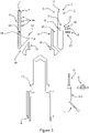
- Figure 2 shows an exploded view of the survey tool 1 shown in figure 1 .
- the survey tool 1 comprises a main body 2 and a cap 29.
- the cap 29 comprises an upper threaded end 30 adapted to be attached to the distal end of a drill string and a lower end for attachment to the main body 2.
- the main body 12 comprises a plastic cover 17 adapted to receive the main body 1.
- the cap 29 comprises an open end adapted to receive the fluid for delivery into the main body 2 of the survey tool 1 for conducting the cleaning process.
- the survey tool 1 comprises a piston 20 adapted to be received by the upper open end of the main body 12.
- the piston 20 is adapted to slide within the main body 2 along the longitudinal axis of the survey tool 1. Sliding of the piston 20 within the main allows selection of the first, second and third cleaning modes of the survey tool 1.
- the survey tool 1 comprises electric motors 15.
- the electric motors 15 are operably connected to the piston 20 to slide the piston 20 within the main body 2.
- the electric motors 15 comprise cords 44 for electrically connecting the motors 15 to batteries 12.
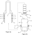
- the batteries 12 are included in a battery housing having an inner wall 8 (see figure 3a and 3b ).
- the housing is slideably received by the lower end of the main body 2.
- a camera 14 is adapted to be attached to the lower end of the main body.
- the camera 14 is operatively connected to the batteries 12.
- the camera 14 comprises a lens.
- the lens is located at the lower end of the main body 2 distal to the cap 29.
- the piston 20 is adapted to selectively slide between an upper location of the main body 2 and a lower location of the main body 2.
- the main body 2 comprises a plurality of passages.
- the passages traverse the walls of the main body longitudinally and transversally.
- the passages permit flow of fluid through the main body via outlets traversing the housing of the main body.
- the main body comprises an outer sleeve 17.
- the outer sleeve 17 comprises outlets 57 that match with the outlets of the passages of the main body 2 to allow passage of the fluid through the outer sleeve 17.
- the survey tool 1 is adapted to provide three cleaning modes which can be selectively chosen by the operator of the survey tool 1. Selection of the particular cleaning mode is possible due to the presence of different type of set of passage. One set of passages allows conducting the first cleaning mode; another set of passages allows conducting the second cleaning mode; and a further set of passages allows conducting the third cleaning mode.
- the first cleaning mode is selected by allowing fluid to exit passages 40 (referred to herein as front jetting passages) - see figure 1 ;
- the second cleaning mode is selected by allowing fluid to exit passages 19 (referred to herein as high volume flushing outlets) - see figure 1 ;
- the third cleaning mode is selected by allowing fluid to exit passages 65 (referred to herein as high pressure jetting passages) - see figure 3 .
- valve means The selection of the particular set of passages 19, 40 and 65 is accomplished by valve means.
- the valve means allows diversion of the fluid into the particular set of passages for selecting a particular cleaning mode.
- valve means comprise the piston 20 that is adapted to move relative to the housing of the main body 2.
- the piston 20 is adapted to be slideably received by the main body 2. And, the cap 29 is adapted to be mounted onto the main body 2 defining a pressure accumulation chamber.
- the piston 20 has a smaller outer wall diameter 25 permitting the piston 20 to be lowered into the lower housing valve body wall 59, defining a first divisional chamber 3 and a second divisional chamber 60.
- the hollow piston 20 is moveable relative to the housing valve body 2 thereby controlling the flow of fluid within the housing 2. In particular, movement of the piston 20 along the longitudinal axis of the main body 2 allows diverting the fluid through the particular set of passages.
- the cap 29 comprises a bore that permits fluid flowing from the drilling rig (or an intervention vessel) to flow down the drillstring into the pressure accumulation dispersion chamber.
- This arrangement allows diverting the fluid into the set of particular passages 19, 40 and 65 depending on the type of cleaning mode that is desired. This is because depending on the particular location of the piston 20 along the longitudinal axis of the main body 2, the piston outer wall 25 blocks the entrance of a pair of passages, while the particular set of passages are left open permitting the fluid to flow through the particular open passages.
- the piston 20 seals the lower housing valve body wall 59 (see figure 3 ). This prevents fluid from flowing past the high volume flushing outlet 19. As the piston 20 travel further down passed the high volume outlet depressing seals 53 (see figure 3 ) the piston 20 depresses seals 47 and seals off the forward jetting passages 40. As the piston 20 retracts into its lowest position, the piston 20 fully seals off the second divisional chamber 60.
- the plurality of high pressure jetting passages 65 in the first expansion chamber 3 are open allowing fluid to flow through the plurality of high pressure jetting passages 65, then through a plurality of the high pressure longitudinally jetting passages 66, and out of the plurality of transvers jetting nozzle outlets 67.
- the outlets 67 may be adapted to receive a high pressure filter nozzle 18.
- the piston 20 has an external piston seal 54 that seals between the external piston wall 25 and the first divisional chamber 3 stopping flow from the first divisional chamber 3 at the external piston seal 54.
- the piston 20 is moved via actuators.
- the actuators comprise a gear box and an electric motor 15, spindle drive worm shaft 16, and spindle drive worm shaft nut 58 (see figures 1 to 3 ).
- the electric motor 15 will have hall sensors built in for determining and providing the location of the piston along the longitudinal axis of the main body 2.
- the motor 15 and the respective gear boxes are screwed and sealed into an elongated spindle gear retaining cap 61 - see figure 3 .
- the spindle gear retaining cap 61 has seals for sealing between the inside of the spindle gear cap 61 and the electric motor 15.
- the motor 15 and the gear boxes are sealed into an elongated spindle gear retaining cap 61.
- the spindle gear retaining cap 61 is placed into passage 62 defined within the main body 2 - see figure 3 .
- the elongated cap 61 comprises a matching recess to accept the elongated cap 61 within the housing 62, the seals 51 seal the gap between the inside of the housing 62 and spindle gear retaining cap 61.
- the motors 15, spindle drive and gear 16 and the spindle gear retaining cap 61 are inserted into an oil filed provision sealed within the housing 62. They are held in place by a circlip 63 (see figure 3 ) screwed or bolted in place.
- the spindle gear retaining cap 61 stops the motor 15 and the spindle gear assembly 16 from rotating inside the passage 62.
- the electric motor 15 comprise a power cable with water proofed connectors 43, gland packing nut and sealing grommet 64 for sealing around power lead 44.
- the base of the piston 20 comprises a threaded gear nut assembly 58 for accepting the spindle shaft 16.
- This tool access port 23 allows for manual manipulation of the spindle drive 16 for the manual removal of the piston 20.
- Access holes 23 will have a grub screw 22 inserted to seal off these passages 23.
- a particular arrangement of the housing of the main body 2 comprises a series of filter recesses 35 adapted to receive at least one filter 36 to be secured by a circlip 63 into the respective circlip retainer position 37.
- This allows for filtering of contaminated flowing fluid flowing through filters 36 from the outside of the housing.
- the filtered fluid may flow through the opening 38 of the filter 36 to the underside of the piston 20. This removes any vacuum formed under the piston 20 that may stop the piston 20 from moving.
- the filtering process will also remove any debris from the fluid avoiding jamming of any parts.
- the electric motor 15 and camera 14 are electrically driven by a battery 12.
- Figure 3a and 3b show the battery 12, circuit board and camera 14.
- the battery 12 comprises a cap 69 having water proof connector 70 for the purpose of allowing the control signals and power to transvers through the battery cap 69 but maintaining a water tight seal.
- the shoulders on the battery cap 69 comprise a seal arrangement on the side wall 71. In this manner, a water tight seal is formed between the matching shoulder 8 of the battery housing.
- the battery cap 60 comprises a plurality of longitudinal holes 72 (not depicted), around the circumference of the cap 60 to fasten the battery within the battery housing.
- the camera 14 is electrically connected to the battery 12.
- an umbilical 56 is passed through an umbilical side port 10 of the camera housing.
- One end of the umbilical 56 is connected to the water tight connector 70 of the battery cap 69.
- the other end of the umbilical 56 is connected to a water tight connector on the camera base 79.
- the umbilical 56 runs between a machined recess in the plastic protection cover and a machined recess in the housing of the main body 2.
- a camera retainer is mounted on the camera 14.
- the camera retainer and the forward flushing ports of the camera retaining housing 73 will line up with the corresponding forward flushing ports.
- the camera retaining housing 73 will have a plurality of transverse camera retaining passages 74, the camera housing retaining grub screws 75 retain the camera housing and holding it tight against rubber seal 55.
- the camera retaining housing 73 comprises protective frame 76 preventing the camera from being damaged
- Figures 4a to 4b show an apparatus according to a second embodiment of the invention.
- the apparatus according to the second embodiment is similar to the apparatus according to the apparatus of the first embodiment and similar reference numerals are used to identify similar parts.
- the second embodiment of the invention differs from the first embodiment of the invention in several features.
- the second embodiment of the invention comprises an electric motor 032 for driving a hydraulic pump.
- the hydraulic fluid driven by the hydraulic pump moves the piston 80 along the longitudinal axis of the main body 2.
- movement of the piston 80 along the longitudinal axis allows selection of the particular cleaning mode.
- Selection of the particular cleaning mode is accomplished by opening a particular set of passages and blocking the remaining set of passages using the piston 20.
- the piston 20 is driven by hydraulic fluid.
- the inner wall of the main body 2 comprises a piston chamber 92.
- the upper end of the piston chamber 92 comprises a piston retainer 98.
- the piston chamber 92 is sealed by a plurality of O-ring seals that are located on (1) the outer circumference of the piston retainer 98 and (2) a plurality of seals 100 located between the inner circumference of the piston retainer 98 and the outer piston wall 82 - see figure 4b .
- the upper piston chamber 92 comprises a shoulder 93 for aligning with the underside of a shoulder 101 of the piston retainer 98.
- the piston retainer 98 comprises a plurality of longitudinal passages bolt holes 103 allowing for bolts to pass through for securing the piston retainer 98 to the housing of the main body 2.
- the hollow internal hydraulic pump piston 80 comprises a protrusion 84 and 86.
- the protrusions 84 and 86 divide the piston chamber 92 into a lower chamber 95 and an upper chamber 96.
- the lower and upper chamber 95, 96 of the piston chamber 92 are sealed from each other by a plurality of O-ring seals which are located in a plurality of grooves in protrusions 84 and 86.
- the upper chamber 96 and the lower chamber 95 are fluidly connected allowing fluid to flow from the upper chamber 96 into the lower chamber 95 for lifting of the piston 80. Fluid may also flow from the lower chamber 95 into the upper chamber 96 for lowering of the piston 80.
- the piston wall comprises a passage 85.
- the piston 80 also comprises a passage 87 having an extension tube 88 defined by a flange 87 facing latterly down.
- the tube 88 is adapted to keep the pickup in fluid.
- the both upper and lower piston 96, 95 chambers are larger than required to accommodate for extra fluid supply removing the need for a fluid supply bottle.
- the passages 85 and 88 are fluidly connected to a hydraulic pump electric motor 032.
- the pump 032 drives the hydraulic fluid between the upper and lower chambers 96 and 95 for displacing the piston 80 along the longitudinal axis of the main body 2
- the electric hydraulic motor 104 is mounted on the inside of the piston 80 via bolts 105.
- the bolts 105 have the appropriate water tight sealing arrangements connecting the motor to the piston 80.
- An oil filled cable 106 is connected through the battery housing with a water tight connector.
- the battery housing comprises a water proof fitting 107.
- the fluid is transferred to the set of passages 67 via at least one passage 65 that traverse the main body 2 at a location adjacent the piston retainer 98. Fluid is provided to the set of passages 67 when the passages 67 are open.
- the passages 67 are in the open condition when the piston 80 has been lowered opening the passages 65.
- the passages 67 are in closed condition when the upper portion of the piston 80 blocks the passage 65.
- a channel 63 is defined in the main body 2 allowing fluid communication between the passages 67 and the inner bore of the main body 2 containing the fluid.
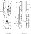
- Figures 5a and 5b show an apparatus according to a third embodiment of the invention.
- the apparatus according to the third embodiment is similar to the apparatus according to the second embodiment and similar reference numerals are used to identify similar parts.
- the third embodiment of the invention differs from the second embodiment of the invention in several features.
- the second embodiment of the invention comprises an electric motor 111 (referred to as the motor 032 in the second embodiment of the invention) attached to the outer wall of the drill string 108 - see figure 5a .
- the electric motor 111 is substantially the same motor 032 of the second embodiment of the invention.
- the motor 111 is adapted to move hydraulic fluid between the upper chamber 96 and the lower chamber 95 for moving of the piston 80 along the longitudinal axis of the main body 2.
- a port 112 traversing the upper piston chamber 96.
- the port 112 is fluidly connected a longitudinal passage 113 going up through the cap 29 attached to a hydraulic tubing 114 that connected to the hydraulic motor 111.
- a port 115 is provided traversing the lower piston chamber 95 and fluidly connected to a longitudinal passage 116 (going up through the cap 29) and fluidly attached to a hydraulic tubing 117 connected to the hydraulic motor 111.
- a port 112 is provided traversing the upper piston chamber 96 and fluidly connected to a longitudinal passage 113 (going up through the cap 29) and fluidly attached to a hydraulic tubing 114 connected to the hydraulic motor 111.
- Upward movement of the piston 109 (referred to as the piston 20 in the second embodiment of the invention) is accomplished by pumping hydraulic fluid into the lower piston chamber 95 through the port 115; lowering of the piston 109 is accomplished by pumping hydraulic fluid into the upper piston chamber 96 through the port 112.
- the both upper and lower piston chambers 96, 95 are larger than required to accommodate for extra fluid supply removing the need for a fluid supply bottle.
- Figures 6a to 6b show an apparatus according to a fourth embodiment of the invention.
- the apparatus according to the fourth embodiment is similar to the apparatus according to the apparatus of the first embodiment and similar reference numerals are used to identify similar parts.
- the third embodiment of the invention differs from the first embodiment of the invention in several features.
- the piston 80 (herein referred to as piston 129) moves along the longitudinal axis of the main body 2 (herein referred to main body 120) by action of an electric motor 140 operatively connected to the lower end of the piston 129.
- the electric motor 140 is operatively connected to a gear box.
- the gear box allows for moving the piston 129 along the longitudinal axis of the main body 120. As mentioned earlier movement of the piston 129 allows selection of the particular cleaning mode to be used.
- the piston comprises a bore for receiving the fluid.
- the survey tool 1 in accordance with the fourth embodiment of the invention comprises a cap 144 for attachment to the drill string (not shown) and to the main body 120.
- the lower end of the cap 144 has an outer thread 145 for attachment to the upper end of the main body 120.
- the cap 144 comprises a seal 124 for sealing on the inside of the body wall 121, the cap 144 will have at least one shoulder 150 for aligning and retaining the cap 144 to the matching housing shoulders 122.
- the cap 144 has a passage that allows for the piston 129 slide along the longitudinal axis of the main body 120. There are provided a plurality of seals for sealing of the inside of piston 129 and the inside of the cap 146 and the outside of the piston 129 against the inside of the main body 121.
- a bleed passage 148 traversing through the main body 120 allows for pressure and vacuum release.
- the piston 129 moves along the longitudinal axis of the main body 120 via an actuator.
- the actuator comprises the electric motor 140 together with the gear box and a spindle drive worm shaft 141.
- a spindle drive worm shaft nut in also incorporated.
- Moving the piston 129 along the longitudinal axis allows selecting the particular cleaning mode to be used. This is because by moving the piston 129 particular passages may be blocked or opened to impede or allow fluid from exiting the survey tool 1 for cleaning purposes.
- the piston 155 comprises a plurality of sets of passages (such as passages 137) allowing the fluid to flow out of the survey tool 1 when the set of passages 137 are in fluid communication with set of passages of the main body 151.
- the main body 120 comprises a plurality of set of passages 123, 136 and 40. Selection of the particular cleaning mode is possible due to the presence of the different type of set of passages 123, 136 and 40.
- One set of passages allows conducting the first cleaning mode; another set of passages allows conducting the second cleaning mode; and a further set of passages allows conducting the third cleaning mode.
- the first cleaning mode is selected by allowing fluid to exit passages 40 (referred to herein as front jetting passages) - see figure 6a ;
- the second cleaning mode is selected by allowing fluid to exit passages 19 (referred to herein as high volume flushing outlets) - see figure 6a ;
- the third cleaning mode is selected by allowing fluid to exit passages 123 (referred to herein as high pressure jetting passages) - see figure 6a .
- the selection of the particular set of passages is accomplished by the movement of the piston 129.
- the different sets of passages are located at different locations along the main body 120 with respect to each other. Locating each set passages at locations that differ from the location of the other set of passages allows selecting (by moving the piston 129) the particular set of passages that will permit flow of the fluid out of the main body 120 for cleaning purposes. The remaining set of passages do not permit fluid flow out of the main body 120 because they are blocked by the wall of the piston 129.
- the electric motors 140 will have hall sensors for determining location of the piston 210.
- the electric motor 140 together with the gear box are screwed and sealed into the water tight battery compartment 149.
- piston 129 is operatively connected to the electric motor 140.
- the lower end of the piston 129 comprises a threaded gear nut assembly 133 for accepting the spindle shaft 141.
- piston 129 is operatively connected to the electric motor allows moving the piston 129 along the longitudinal axis of the main body 120.
- moving of the piston 120 allows selecting the particular cleaning mode to be used.
- Figures 7a to 7b show an apparatus according to a fifth embodiment of the invention.
- the apparatus according to the fifth embodiment is similar to the apparatus according to the apparatus of the fourth embodiment and similar reference numerals are used to identify similar parts.
- the fifth embodiment of the invention differs from the fourth embodiment of the invention in several features.
- the fifth embodiment of the invention comprises a piston 155 (referred to as 129 in the fourth embodiment of the invention) that is adapted to rotate.
- Rotation of the piston 155 around the longitudinal axis allows selecting the particular cleaning mode to be used. This is because by rotating the piston 155 particular passages may be blocked or opened to impede or allow fluid from exiting the survey tool 1 for cleaning purposes.
- the piston 155 comprises a plurality of sets of passages (such as passages 157) allowing the fluid to flow out of the survey tool 1 when the set of passages 157 are in fluid communication with set of passages of the main body 151.
- the main body 152 comprises a plurality of set of passages 154, 19 and 40. Selection of the particular cleaning mode is possible due to the presence of the different type of set of passages 154, 19 and 40.
- One set of passages allows conducting the first cleaning mode; another set of passages allows conducting the second cleaning mode; and a further set of passages allows conducting the third cleaning mode.
- the first cleaning mode is selected by allowing fluid to exit passages 40 (referred to herein as front jetting passages) - see figure 7a ;
- the second cleaning mode is selected by allowing fluid to exit passages 19 (referred to herein as high volume flushing outlets) - see figure 7a ;
- the third cleaning mode is selected by allowing fluid to exit passages 154 (referred to herein as high pressure jetting passages) - see figure 7a .
- the selection of the particular set of passages is accomplished by the rotation of the piston 155.
- the different sets of passages are located at different locations around the main body 152 with respect to each other. Locating each set passages at locations (around the longitudinal axis of the main body 152) that differ from the location of the other set of passages allows selecting (by rotating the piston 155) the particular set of passages that will permit flow of the fluid out of the main body 152 for cleaning purposes. The remaining set of passages do not permit fluid flow out of the main body 152 because they are blocked by the wall of the piston 155.
- the piston 155 is rotated due to the action of an actuator.
- the actuator comprises an electric motor 158.
- the actuator comprises an electric motor and gear box 158 with a cog 159 to engage with the gear in the underside of the piston 155 for rotating the piston 155.
- the survey tool 1 in accordance with the present embodiments of the invention may incorporate a one way flap valve 170. It is particularly advantageous that the survey tool 19 comprises the flap valve 170 because it stops fluid from the borehole flowing onto the drilling rig. In alternative arrangements there may be provided a one way flap valve pup attached between the drill string and the survey tool to avoid fluid from flowing into the drilling rig.
- the survey tool 1 in accordance with the present embodiments of the invention may incorporate a basket 172 for receiving and collecting any debris stopping the debris from falling into the well.
- the cleaning process and viewing process may be still operated while the basket 172 is attached to the survey tool 1.
- the basket is attached via one or more brackets 176.
- the scope of the invention is not limited to the scope of the embodiments disclosed.
- the above descriptions have been described in relation to a downhole survey tool for use in a well.
- the present survey tool 1 may be used for any type of drilling operation may it be vertical, horizontal or directional drilling.
- the terms "proximal” and “distal” may be (respectively) more appropriate than the terms “upper” and “lower” used in the previous descriptions.
- the terms “upper” and “lower” are used in the previous description in view that the first to fifth embodiments of the invention relate to downhole survey tools for use in a well.
- the scope of the present of the invention is not limited to vertical drilling process.
Landscapes
- Engineering & Computer Science (AREA)
- Geology (AREA)
- Life Sciences & Earth Sciences (AREA)
- Mining & Mineral Resources (AREA)
- Physics & Mathematics (AREA)
- Geochemistry & Mineralogy (AREA)
- Fluid Mechanics (AREA)
- General Life Sciences & Earth Sciences (AREA)
- Environmental & Geological Engineering (AREA)
- Geophysics (AREA)
- Mechanical Engineering (AREA)
- Earth Drilling (AREA)
- Actuator (AREA)
- Cleaning In General (AREA)
- Investigation Of Foundation Soil And Reinforcement Of Foundation Soil By Compacting Or Drainage (AREA)
- Manipulator (AREA)
- Endoscopes (AREA)
Claims (14)
- Outil (1) pour le nettoyage d'une caméra (14), de surfaces internes d'un trou de forage à inspecter et/ou d'une surface interne BOP d'un puits, l'outil étant conçu pour être fixé à un train de tiges de forage 180 pour insérer l'outil dans le trou de forage, l'outil comprenant un corps (2, 120, 151) ayant une extrémité proximale conçue pour recevoir du fluide depuis le train de tiges de forage (108) et une extrémité distale pour recevoir la caméra (14), une paroi ayant une surface interne définissant un premier alésage à l'intérieur du corps (2, 120, 151) et une surface extérieure définissant au moins une partie de l'extérieur du corps (2, 120, 151), et un piston (20, 80, 129, 109) conçu pour être déplacé à l'intérieur du premier alésage,
dans lequel la paroi comprend une pluralité de passages (19, 40 et 65) s'étendant entre le premier alésage et la surface extérieure pour permettre une communication entre l'extérieur du corps et le premier alésage ; et le piston (20, 80, 129, 109) étant conçu pour être déplacé sélectivement entre une première condition pour permettre au fluide de s'écouler à travers au moins un premier passage (65) de la pluralité de passages (19, 40 et 65) pour une distribution du fluide vers un premier emplacement du trou de forage, une deuxième condition pour permettre au fluide de s'écouler à travers au moins un deuxième passage (19) de la pluralité de passages (19, 40 et 65) afin de distribuer le fluide vers un deuxième emplacement du trou de forage, et une troisième condition pour permettre au fluide de s'écouler à travers au moins un troisième passage (40) de la pluralité de passages (19, 40 et 65) afin de distribuer le fluide vers l'extrémité distale du corps de l'outil. - Outil selon la revendication 1, dans lequel le premier emplacement du trou de forage comprend une zone du trou de forage adjacente à la paroi de l'outil (1) et le deuxième emplacement du trou de forage comprend une zone du trou de forage à étudier par la caméra.
- Outil selon l'une quelconque des revendications précédentes, dans lequel le piston (20, 80, 129, 109) comprend un second alésage pour recevoir le fluide depuis le train de tiges de forage (108).
- Outil selon la revendication 3, dans lequel le piston comprend une pluralité de quatrièmes passages (137, 157) permettant au fluide de s'écouler, respectivement, du second alésage vers l'un quelconque parmi l'au moins un premier (65), deuxième (19) ou troisième passages (40) de la paroi de l'outil lors du déplacement du piston (20, 80, 129, 109) entre les première, deuxième et troisième conditions.
- Outil selon l'une quelconque des revendications, dans lequel le piston (20, 109) est conçu pour être déplacé sélectivement le long de l'axe longitudinal et/ou tourné sélectivement autour du premier alésage entre la première condition et la deuxième condition, ou entre la première condition, la deuxième condition et la troisième condition.
- Outil selon l'une quelconque des revendications précédentes, dans lequel l'au moins un premier passage (65) comprend des passages à volume élevé, au moins un deuxième passage (19) comprend des passages de jet à haute pression et au moins un troisième passage (40) comprend des passages de jet avant.
- Outil selon les revendications 5 ou 6, dans lequel lorsque le piston (20, 80, 129, 109) est dans le premier emplacement, le piston (20, 80, 129, 109) permet au fluide de sortir du logement à travers les passages à volume élevé (65) mais empêche le fluide de s'écouler à travers les passages de jet avant (40) et à travers les passages de jet à haute pression (19), lorsque le piston (20, 80, 129, 109) est dans le deuxième emplacement, le piston (20, 80, 129, 109) permet au fluide de sortir du logement à travers les passages de jet à haute pression (19) mais empêche le fluide de s'écouler à travers les passages à volume élevé (65) et à travers les passages de jet avant (40), et lorsque le piston (2, 109) est dans le troisième emplacement, le piston (20, 80, 129, 109) permet au fluide de sortir du logement à travers les passages de jet avant (40) mais empêche le fluide de s'écouler à travers les passages à volume élevé (65) et à travers les passages de jet à haute pression (40).
- Outil selon l'une quelconque des revendications précédentes, dans lequel le piston (20, 80, 129, 109) est connecté fonctionnellement à au moins un actionneur pour le déplacement du piston (20, 80, 129, 109) le long de l'axe longitudinal du corps (2, 120, 151) de l'outil et/ou la rotation autour de l'axe du corps (2, 120, 151) de l'outil.
- Outil selon l'une quelconque des revendications précédentes, comprenant en outre un manchon externe (17) comprenant des sorties (57) étant en communication fluidique avec la pluralité de passages (19, 40 et 65) du corps (2, 120, 151) permettant le passage du fluide à travers les sorties (57) du manchon externe (17).
- Outil selon l'une quelconque des revendications 6 à 9, dans lequel les passages de jet à haute pression (19) comprennent des buses de filtre à haute pression pour filtrer le fluide.
- Outil selon l'une quelconque des revendications précédentes, comprenant en outre une source d'énergie électrique (12) conçue pour être connectée électriquement à des moteurs électriques (15) et à la caméra (14).
- Outil selon l'une quelconque des revendications précédentes, dans lequel l'extrémité proximale du corps (2, 120, 151) de l'outil (1) comprend une soupape à clapet anti-retour (170) ou une pompe à clapet anti-retour et/ou l'extrémité distale du corps (2, 120, 151) de l'outil comprend un panier (172) conçu pour collecter les débris.
- Train de tiges de forage comprenant l'outil (1) selon l'une quelconque des revendications précédentes.
- Caméra de fond de trou constituée par l'outil (1) selon l'une quelconque des revendications 1 à 12.
Applications Claiming Priority (2)
| Application Number | Priority Date | Filing Date | Title |
|---|---|---|---|
| AU2014901783A AU2014901783A0 (en) | 2014-05-12 | Flushing and jetting camera | |
| PCT/AU2015/000276 WO2015172179A1 (fr) | 2014-05-12 | 2015-05-12 | Outil de fond de trou |
Publications (3)
| Publication Number | Publication Date |
|---|---|
| EP3143253A1 EP3143253A1 (fr) | 2017-03-22 |
| EP3143253A4 EP3143253A4 (fr) | 2018-03-14 |
| EP3143253B1 true EP3143253B1 (fr) | 2022-11-09 |
Family
ID=54479034
Family Applications (1)
| Application Number | Title | Priority Date | Filing Date |
|---|---|---|---|
| EP15793502.4A Active EP3143253B1 (fr) | 2014-05-12 | 2015-05-12 | Outil de fond de trou |
Country Status (13)
| Country | Link |
|---|---|
| US (1) | US10590753B2 (fr) |
| EP (1) | EP3143253B1 (fr) |
| JP (1) | JP2017516005A (fr) |
| KR (1) | KR20170013900A (fr) |
| CN (1) | CN107109921A (fr) |
| AU (1) | AU2015258757B2 (fr) |
| CA (1) | CA2948680A1 (fr) |
| CL (1) | CL2016002887A1 (fr) |
| MX (1) | MX2016014822A (fr) |
| PH (1) | PH12016502426A1 (fr) |
| RU (1) | RU2728630C2 (fr) |
| SG (1) | SG11201609430TA (fr) |
| WO (1) | WO2015172179A1 (fr) |
Families Citing this family (2)
| Publication number | Priority date | Publication date | Assignee | Title |
|---|---|---|---|---|
| CN111946326B (zh) * | 2020-08-24 | 2023-10-27 | 山西银锋科技有限公司 | 一种钻孔窥视仪装置及其使用方法 |
| CN114534370B (zh) * | 2022-03-29 | 2023-04-11 | 无锡亚舟精机有限公司 | 一种洗车污水处理系统及其前置清洗机 |
Family Cites Families (18)
| Publication number | Priority date | Publication date | Assignee | Title |
|---|---|---|---|---|
| US1790678A (en) * | 1924-03-20 | 1931-02-03 | Reinhold Thomas | Apparatus for washing boreholes |
| US1964264A (en) * | 1929-12-21 | 1934-06-26 | James O Mack | Apparatus for cleaning wells |
| US1944434A (en) * | 1932-11-07 | 1934-01-23 | Edgar D Keeler | Bailer |
| US2737864A (en) * | 1951-11-09 | 1956-03-13 | Robert P Gutterman | Borehole camera |
| US2912495A (en) * | 1956-02-03 | 1959-11-10 | Moon James | Device for viewing oil well bore hole |
| US4442899A (en) * | 1982-01-06 | 1984-04-17 | Downhole Services, Inc. | Hydraulic jet well cleaning assembly using a non-rotating tubing string |
| US4905775A (en) * | 1988-09-15 | 1990-03-06 | Amoco Corporation | Drilling system and flow control apparatus for downhole drilling motors |
| US4938060A (en) | 1988-12-30 | 1990-07-03 | Otis Engineering Corp. | Downhole inspection system |
| US5275038A (en) * | 1991-05-20 | 1994-01-04 | Otis Engineering Corporation | Downhole reeled tubing inspection system with fiberoptic cable |
| GB9809411D0 (en) * | 1998-05-02 | 1998-07-01 | Drentham Susman Hector F A Van | Jet cleaning apparatus |
| GB9915885D0 (en) * | 1999-07-08 | 1999-09-08 | Lee Paul B | Downhole valve for use with a drillstring |
| DE602006006559D1 (de) * | 2006-06-15 | 2009-06-10 | Schlumberger Technology Bv | Vorrichtung und Verfahren zur Darstellung von Bildern einer Bohrlochwand |
| RU2381360C1 (ru) * | 2008-10-28 | 2010-02-10 | Закрытое акционерное общество "Геокомсервис" | Способ визуального исследования скважины |
| EP2472056B1 (fr) * | 2010-12-30 | 2016-10-12 | Maxamcorp Holding, S.L. | Système d'inspection de trou de forage et procédé de chargement des trous de mine |
| CN102943638B (zh) * | 2012-09-07 | 2015-03-25 | 钱海鹰 | 大直径深井水射流清洗系统 |
| CN102877808B (zh) * | 2012-10-24 | 2014-12-31 | 中国水利水电第三工程局有限公司 | 一种摄像定位分段爆破处理堵井的方法 |
| US9581011B2 (en) * | 2013-07-04 | 2017-02-28 | Schlumberger Technology Corporation | Downhole imaging systems and methods |
| US9359872B2 (en) * | 2014-05-21 | 2016-06-07 | Baker Hughes Incorporated | Downhole system with filtering and method |
-
2015
- 2015-05-12 WO PCT/AU2015/000276 patent/WO2015172179A1/fr not_active Ceased
- 2015-05-12 SG SG11201609430TA patent/SG11201609430TA/en unknown
- 2015-05-12 JP JP2017512070A patent/JP2017516005A/ja active Pending
- 2015-05-12 RU RU2016148405A patent/RU2728630C2/ru active
- 2015-05-12 MX MX2016014822A patent/MX2016014822A/es unknown
- 2015-05-12 KR KR1020167034677A patent/KR20170013900A/ko not_active Withdrawn
- 2015-05-12 EP EP15793502.4A patent/EP3143253B1/fr active Active
- 2015-05-12 CN CN201580037463.8A patent/CN107109921A/zh active Pending
- 2015-05-12 US US15/310,187 patent/US10590753B2/en not_active Expired - Fee Related
- 2015-05-12 CA CA2948680A patent/CA2948680A1/fr not_active Abandoned
- 2015-05-12 AU AU2015258757A patent/AU2015258757B2/en not_active Ceased
-
2016
- 2016-11-14 CL CL2016002887A patent/CL2016002887A1/es unknown
- 2016-12-05 PH PH12016502426A patent/PH12016502426A1/en unknown
Also Published As
| Publication number | Publication date |
|---|---|
| CL2016002887A1 (es) | 2017-05-26 |
| EP3143253A1 (fr) | 2017-03-22 |
| CA2948680A1 (fr) | 2015-11-19 |
| AU2015258757B2 (en) | 2019-11-21 |
| US10590753B2 (en) | 2020-03-17 |
| JP2017516005A (ja) | 2017-06-15 |
| CN107109921A (zh) | 2017-08-29 |
| EP3143253A4 (fr) | 2018-03-14 |
| MX2016014822A (es) | 2017-07-24 |
| RU2728630C2 (ru) | 2020-07-30 |
| US20170260844A1 (en) | 2017-09-14 |
| SG11201609430TA (en) | 2016-12-29 |
| RU2016148405A (ru) | 2018-06-18 |
| PH12016502426A1 (en) | 2017-02-27 |
| KR20170013900A (ko) | 2017-02-07 |
| RU2016148405A3 (fr) | 2018-11-23 |
| AU2015258757A1 (en) | 2017-01-05 |
| WO2015172179A1 (fr) | 2015-11-19 |
Similar Documents
| Publication | Publication Date | Title |
|---|---|---|
| EP0995011B1 (fr) | Procede et dispositif polyvalent ameliores pour la distribution et la circulation de fluide dans un tubage de puits de forage | |
| US7055611B2 (en) | Plug-dropping container for releasing a plug into a wellbore | |
| CN101802342A (zh) | 具有整体伸缩的保持构件连接装置的密封胶皮 | |
| US20110278007A1 (en) | Tool and method for providing access to a wellhead annulus | |
| CN1703565A (zh) | 钻探泥浆过滤设备 | |
| EP3143253B1 (fr) | Outil de fond de trou | |
| KR100636594B1 (ko) | 지면에 보어홀을 뚫는 방법 및 습식보링기 | |
| US8360156B1 (en) | Method and apparatus for preventing spillage or loss of drill fluids | |
| US8607857B2 (en) | Vacuum debris removal with articulated pickup and visual capability | |
| NO337795B1 (no) | Fremgangsmåte og apparatur for å håndtere fluider i løpet av en operasjon med undersjøisk topphull eller riserløs boring | |
| US20100224358A1 (en) | Casing Device | |
| US12553306B2 (en) | Leak containment system | |
| US12338715B1 (en) | Cleaning and inspecting a wellbore | |
| US12618325B2 (en) | Dynamic multi-flowline control system for downhole tools | |
| US20250250896A1 (en) | Dynamic multi-flowline control system for downhole tools | |
| HK1074068B (en) | Wet boring tool, boring plant and method for sinking a borehole in the ground |
Legal Events
| Date | Code | Title | Description |
|---|---|---|---|
| STAA | Information on the status of an ep patent application or granted ep patent |
Free format text: STATUS: THE INTERNATIONAL PUBLICATION HAS BEEN MADE |
|
| PUAI | Public reference made under article 153(3) epc to a published international application that has entered the european phase |
Free format text: ORIGINAL CODE: 0009012 |
|
| STAA | Information on the status of an ep patent application or granted ep patent |
Free format text: STATUS: REQUEST FOR EXAMINATION WAS MADE |
|
| 17P | Request for examination filed |
Effective date: 20161201 |
|
| AK | Designated contracting states |
Kind code of ref document: A1 Designated state(s): AL AT BE BG CH CY CZ DE DK EE ES FI FR GB GR HR HU IE IS IT LI LT LU LV MC MK MT NL NO PL PT RO RS SE SI SK SM TR |
|
| AX | Request for extension of the european patent |
Extension state: BA ME |
|
| DAV | Request for validation of the european patent (deleted) | ||
| DAX | Request for extension of the european patent (deleted) | ||
| A4 | Supplementary search report drawn up and despatched |
Effective date: 20180208 |
|
| RIC1 | Information provided on ipc code assigned before grant |
Ipc: E21B 47/00 20120101ALI20180202BHEP Ipc: E21B 21/00 20060101ALI20180202BHEP Ipc: E21B 27/00 20060101ALI20180202BHEP Ipc: E21B 47/01 20120101ALI20180202BHEP Ipc: E21B 34/06 20060101ALI20180202BHEP Ipc: E21B 47/12 20120101AFI20180202BHEP Ipc: E21B 37/00 20060101ALI20180202BHEP |
|
| STAA | Information on the status of an ep patent application or granted ep patent |
Free format text: STATUS: EXAMINATION IS IN PROGRESS |
|
| 17Q | First examination report despatched |
Effective date: 20190321 |
|
| REG | Reference to a national code |
Ref country code: DE Ref legal event code: R079 Ref document number: 602015081541 Country of ref document: DE Free format text: PREVIOUS MAIN CLASS: E21B0047120000 Ipc: E21B0047002000 |
|
| RIC1 | Information provided on ipc code assigned before grant |
Ipc: E21B 47/017 20120101ALI20220315BHEP Ipc: E21B 47/002 20120101AFI20220315BHEP |
|
| GRAP | Despatch of communication of intention to grant a patent |
Free format text: ORIGINAL CODE: EPIDOSNIGR1 |
|
| STAA | Information on the status of an ep patent application or granted ep patent |
Free format text: STATUS: GRANT OF PATENT IS INTENDED |
|
| INTG | Intention to grant announced |
Effective date: 20220512 |
|
| GRAS | Grant fee paid |
Free format text: ORIGINAL CODE: EPIDOSNIGR3 |
|
| GRAA | (expected) grant |
Free format text: ORIGINAL CODE: 0009210 |
|
| STAA | Information on the status of an ep patent application or granted ep patent |
Free format text: STATUS: THE PATENT HAS BEEN GRANTED |
|
| AK | Designated contracting states |
Kind code of ref document: B1 Designated state(s): AL AT BE BG CH CY CZ DE DK EE ES FI FR GB GR HR HU IE IS IT LI LT LU LV MC MK MT NL NO PL PT RO RS SE SI SK SM TR |
|
| REG | Reference to a national code |
Ref country code: GB Ref legal event code: FG4D |
|
| REG | Reference to a national code |
Ref country code: CH Ref legal event code: EP Ref country code: AT Ref legal event code: REF Ref document number: 1530490 Country of ref document: AT Kind code of ref document: T Effective date: 20221115 |
|
| REG | Reference to a national code |
Ref country code: DE Ref legal event code: R096 Ref document number: 602015081541 Country of ref document: DE |
|
| REG | Reference to a national code |
Ref country code: IE Ref legal event code: FG4D |
|
| REG | Reference to a national code |
Ref country code: LT Ref legal event code: MG9D |
|
| REG | Reference to a national code |
Ref country code: NL Ref legal event code: MP Effective date: 20221109 |
|
| REG | Reference to a national code |
Ref country code: NO Ref legal event code: T2 Effective date: 20221109 |
|
| REG | Reference to a national code |
Ref country code: AT Ref legal event code: MK05 Ref document number: 1530490 Country of ref document: AT Kind code of ref document: T Effective date: 20221109 |
|
| PG25 | Lapsed in a contracting state [announced via postgrant information from national office to epo] |
Ref country code: SE Free format text: LAPSE BECAUSE OF FAILURE TO SUBMIT A TRANSLATION OF THE DESCRIPTION OR TO PAY THE FEE WITHIN THE PRESCRIBED TIME-LIMIT Effective date: 20221109 Ref country code: PT Free format text: LAPSE BECAUSE OF FAILURE TO SUBMIT A TRANSLATION OF THE DESCRIPTION OR TO PAY THE FEE WITHIN THE PRESCRIBED TIME-LIMIT Effective date: 20230309 Ref country code: LT Free format text: LAPSE BECAUSE OF FAILURE TO SUBMIT A TRANSLATION OF THE DESCRIPTION OR TO PAY THE FEE WITHIN THE PRESCRIBED TIME-LIMIT Effective date: 20221109 Ref country code: FI Free format text: LAPSE BECAUSE OF FAILURE TO SUBMIT A TRANSLATION OF THE DESCRIPTION OR TO PAY THE FEE WITHIN THE PRESCRIBED TIME-LIMIT Effective date: 20221109 Ref country code: ES Free format text: LAPSE BECAUSE OF FAILURE TO SUBMIT A TRANSLATION OF THE DESCRIPTION OR TO PAY THE FEE WITHIN THE PRESCRIBED TIME-LIMIT Effective date: 20221109 Ref country code: AT Free format text: LAPSE BECAUSE OF FAILURE TO SUBMIT A TRANSLATION OF THE DESCRIPTION OR TO PAY THE FEE WITHIN THE PRESCRIBED TIME-LIMIT Effective date: 20221109 |
|
| PG25 | Lapsed in a contracting state [announced via postgrant information from national office to epo] |
Ref country code: RS Free format text: LAPSE BECAUSE OF FAILURE TO SUBMIT A TRANSLATION OF THE DESCRIPTION OR TO PAY THE FEE WITHIN THE PRESCRIBED TIME-LIMIT Effective date: 20221109 Ref country code: PL Free format text: LAPSE BECAUSE OF FAILURE TO SUBMIT A TRANSLATION OF THE DESCRIPTION OR TO PAY THE FEE WITHIN THE PRESCRIBED TIME-LIMIT Effective date: 20221109 Ref country code: LV Free format text: LAPSE BECAUSE OF FAILURE TO SUBMIT A TRANSLATION OF THE DESCRIPTION OR TO PAY THE FEE WITHIN THE PRESCRIBED TIME-LIMIT Effective date: 20221109 Ref country code: IS Free format text: LAPSE BECAUSE OF FAILURE TO SUBMIT A TRANSLATION OF THE DESCRIPTION OR TO PAY THE FEE WITHIN THE PRESCRIBED TIME-LIMIT Effective date: 20230309 Ref country code: HR Free format text: LAPSE BECAUSE OF FAILURE TO SUBMIT A TRANSLATION OF THE DESCRIPTION OR TO PAY THE FEE WITHIN THE PRESCRIBED TIME-LIMIT Effective date: 20221109 Ref country code: GR Free format text: LAPSE BECAUSE OF FAILURE TO SUBMIT A TRANSLATION OF THE DESCRIPTION OR TO PAY THE FEE WITHIN THE PRESCRIBED TIME-LIMIT Effective date: 20230210 |
|
| PG25 | Lapsed in a contracting state [announced via postgrant information from national office to epo] |
Ref country code: NL Free format text: LAPSE BECAUSE OF FAILURE TO SUBMIT A TRANSLATION OF THE DESCRIPTION OR TO PAY THE FEE WITHIN THE PRESCRIBED TIME-LIMIT Effective date: 20221109 |
|
| PG25 | Lapsed in a contracting state [announced via postgrant information from national office to epo] |
Ref country code: SM Free format text: LAPSE BECAUSE OF FAILURE TO SUBMIT A TRANSLATION OF THE DESCRIPTION OR TO PAY THE FEE WITHIN THE PRESCRIBED TIME-LIMIT Effective date: 20221109 Ref country code: RO Free format text: LAPSE BECAUSE OF FAILURE TO SUBMIT A TRANSLATION OF THE DESCRIPTION OR TO PAY THE FEE WITHIN THE PRESCRIBED TIME-LIMIT Effective date: 20221109 Ref country code: EE Free format text: LAPSE BECAUSE OF FAILURE TO SUBMIT A TRANSLATION OF THE DESCRIPTION OR TO PAY THE FEE WITHIN THE PRESCRIBED TIME-LIMIT Effective date: 20221109 Ref country code: DK Free format text: LAPSE BECAUSE OF FAILURE TO SUBMIT A TRANSLATION OF THE DESCRIPTION OR TO PAY THE FEE WITHIN THE PRESCRIBED TIME-LIMIT Effective date: 20221109 Ref country code: CZ Free format text: LAPSE BECAUSE OF FAILURE TO SUBMIT A TRANSLATION OF THE DESCRIPTION OR TO PAY THE FEE WITHIN THE PRESCRIBED TIME-LIMIT Effective date: 20221109 |
|
| PGFP | Annual fee paid to national office [announced via postgrant information from national office to epo] |
Ref country code: NO Payment date: 20230519 Year of fee payment: 9 |
|
| REG | Reference to a national code |
Ref country code: DE Ref legal event code: R097 Ref document number: 602015081541 Country of ref document: DE |
|
| PG25 | Lapsed in a contracting state [announced via postgrant information from national office to epo] |
Ref country code: SK Free format text: LAPSE BECAUSE OF FAILURE TO SUBMIT A TRANSLATION OF THE DESCRIPTION OR TO PAY THE FEE WITHIN THE PRESCRIBED TIME-LIMIT Effective date: 20221109 Ref country code: AL Free format text: LAPSE BECAUSE OF FAILURE TO SUBMIT A TRANSLATION OF THE DESCRIPTION OR TO PAY THE FEE WITHIN THE PRESCRIBED TIME-LIMIT Effective date: 20221109 |
|
| PLBE | No opposition filed within time limit |
Free format text: ORIGINAL CODE: 0009261 |
|
| STAA | Information on the status of an ep patent application or granted ep patent |
Free format text: STATUS: NO OPPOSITION FILED WITHIN TIME LIMIT |
|
| 26N | No opposition filed |
Effective date: 20230810 |
|
| PGFP | Annual fee paid to national office [announced via postgrant information from national office to epo] |
Ref country code: GB Payment date: 20230508 Year of fee payment: 9 |
|
| PG25 | Lapsed in a contracting state [announced via postgrant information from national office to epo] |
Ref country code: SI Free format text: LAPSE BECAUSE OF FAILURE TO SUBMIT A TRANSLATION OF THE DESCRIPTION OR TO PAY THE FEE WITHIN THE PRESCRIBED TIME-LIMIT Effective date: 20221109 |
|
| REG | Reference to a national code |
Ref country code: DE Ref legal event code: R119 Ref document number: 602015081541 Country of ref document: DE |
|
| REG | Reference to a national code |
Ref country code: CH Ref legal event code: PL |
|
| PG25 | Lapsed in a contracting state [announced via postgrant information from national office to epo] |
Ref country code: MC Free format text: LAPSE BECAUSE OF FAILURE TO SUBMIT A TRANSLATION OF THE DESCRIPTION OR TO PAY THE FEE WITHIN THE PRESCRIBED TIME-LIMIT Effective date: 20221109 |
|
| REG | Reference to a national code |
Ref country code: BE Ref legal event code: MM Effective date: 20230531 |
|
| PG25 | Lapsed in a contracting state [announced via postgrant information from national office to epo] |
Ref country code: MC Free format text: LAPSE BECAUSE OF FAILURE TO SUBMIT A TRANSLATION OF THE DESCRIPTION OR TO PAY THE FEE WITHIN THE PRESCRIBED TIME-LIMIT Effective date: 20221109 Ref country code: LU Free format text: LAPSE BECAUSE OF NON-PAYMENT OF DUE FEES Effective date: 20230512 Ref country code: LI Free format text: LAPSE BECAUSE OF NON-PAYMENT OF DUE FEES Effective date: 20230531 Ref country code: CH Free format text: LAPSE BECAUSE OF NON-PAYMENT OF DUE FEES Effective date: 20230531 |
|
| REG | Reference to a national code |
Ref country code: IE Ref legal event code: MM4A |
|
| PG25 | Lapsed in a contracting state [announced via postgrant information from national office to epo] |
Ref country code: IE Free format text: LAPSE BECAUSE OF NON-PAYMENT OF DUE FEES Effective date: 20230512 |
|
| PG25 | Lapsed in a contracting state [announced via postgrant information from national office to epo] |
Ref country code: IE Free format text: LAPSE BECAUSE OF NON-PAYMENT OF DUE FEES Effective date: 20230512 Ref country code: DE Free format text: LAPSE BECAUSE OF NON-PAYMENT OF DUE FEES Effective date: 20231201 |
|
| PG25 | Lapsed in a contracting state [announced via postgrant information from national office to epo] |
Ref country code: IT Free format text: LAPSE BECAUSE OF FAILURE TO SUBMIT A TRANSLATION OF THE DESCRIPTION OR TO PAY THE FEE WITHIN THE PRESCRIBED TIME-LIMIT Effective date: 20221109 Ref country code: FR Free format text: LAPSE BECAUSE OF NON-PAYMENT OF DUE FEES Effective date: 20230531 Ref country code: BE Free format text: LAPSE BECAUSE OF NON-PAYMENT OF DUE FEES Effective date: 20230531 |
|
| PG25 | Lapsed in a contracting state [announced via postgrant information from national office to epo] |
Ref country code: BG Free format text: LAPSE BECAUSE OF FAILURE TO SUBMIT A TRANSLATION OF THE DESCRIPTION OR TO PAY THE FEE WITHIN THE PRESCRIBED TIME-LIMIT Effective date: 20221109 |
|
| PG25 | Lapsed in a contracting state [announced via postgrant information from national office to epo] |
Ref country code: BG Free format text: LAPSE BECAUSE OF FAILURE TO SUBMIT A TRANSLATION OF THE DESCRIPTION OR TO PAY THE FEE WITHIN THE PRESCRIBED TIME-LIMIT Effective date: 20221109 |
|
| PG25 | Lapsed in a contracting state [announced via postgrant information from national office to epo] |
Ref country code: NO Free format text: LAPSE BECAUSE OF NON-PAYMENT OF DUE FEES Effective date: 20240531 |
|
| GBPC | Gb: european patent ceased through non-payment of renewal fee |
Effective date: 20240512 |
|
| PG25 | Lapsed in a contracting state [announced via postgrant information from national office to epo] |
Ref country code: NO Free format text: LAPSE BECAUSE OF NON-PAYMENT OF DUE FEES Effective date: 20240531 |
|
| PG25 | Lapsed in a contracting state [announced via postgrant information from national office to epo] |
Ref country code: GB Free format text: LAPSE BECAUSE OF NON-PAYMENT OF DUE FEES Effective date: 20240512 |
|
| PG25 | Lapsed in a contracting state [announced via postgrant information from national office to epo] |
Ref country code: CY Free format text: LAPSE BECAUSE OF FAILURE TO SUBMIT A TRANSLATION OF THE DESCRIPTION OR TO PAY THE FEE WITHIN THE PRESCRIBED TIME-LIMIT; INVALID AB INITIO Effective date: 20150512 |
|
| PG25 | Lapsed in a contracting state [announced via postgrant information from national office to epo] |
Ref country code: HU Free format text: LAPSE BECAUSE OF FAILURE TO SUBMIT A TRANSLATION OF THE DESCRIPTION OR TO PAY THE FEE WITHIN THE PRESCRIBED TIME-LIMIT; INVALID AB INITIO Effective date: 20150512 |
|
| PG25 | Lapsed in a contracting state [announced via postgrant information from national office to epo] |
Ref country code: TR Free format text: LAPSE BECAUSE OF FAILURE TO SUBMIT A TRANSLATION OF THE DESCRIPTION OR TO PAY THE FEE WITHIN THE PRESCRIBED TIME-LIMIT Effective date: 20221109 |