EP3143258B1 - Kolbenmaschine mit kühlung - Google Patents
Kolbenmaschine mit kühlung Download PDFInfo
- Publication number
- EP3143258B1 EP3143258B1 EP15726873.1A EP15726873A EP3143258B1 EP 3143258 B1 EP3143258 B1 EP 3143258B1 EP 15726873 A EP15726873 A EP 15726873A EP 3143258 B1 EP3143258 B1 EP 3143258B1
- Authority
- EP
- European Patent Office
- Prior art keywords
- piston
- wall
- cooling
- housing
- circular arc
- Prior art date
- Legal status (The legal status is an assumption and is not a legal conclusion. Google has not performed a legal analysis and makes no representation as to the accuracy of the status listed.)
- Active
Links
Images






Classifications
-
- F—MECHANICAL ENGINEERING; LIGHTING; HEATING; WEAPONS; BLASTING
- F04—POSITIVE - DISPLACEMENT MACHINES FOR LIQUIDS; PUMPS FOR LIQUIDS OR ELASTIC FLUIDS
- F04C—ROTARY-PISTON, OR OSCILLATING-PISTON, POSITIVE-DISPLACEMENT MACHINES FOR LIQUIDS; ROTARY-PISTON, OR OSCILLATING-PISTON, POSITIVE-DISPLACEMENT PUMPS
- F04C15/00—Component parts, details or accessories of machines, pumps or pumping installations, not provided for in groups F04C2/00 - F04C14/00
- F04C15/0096—Heating; Cooling
-
- F—MECHANICAL ENGINEERING; LIGHTING; HEATING; WEAPONS; BLASTING
- F01—MACHINES OR ENGINES IN GENERAL; ENGINE PLANTS IN GENERAL; STEAM ENGINES
- F01C—ROTARY-PISTON OR OSCILLATING-PISTON MACHINES OR ENGINES
- F01C21/00—Component parts, details or accessories not provided for in groups F01C1/00 - F01C20/00
- F01C21/10—Outer members for co-operation with rotary pistons; Casings
-
- F—MECHANICAL ENGINEERING; LIGHTING; HEATING; WEAPONS; BLASTING
- F01—MACHINES OR ENGINES IN GENERAL; ENGINE PLANTS IN GENERAL; STEAM ENGINES
- F01C—ROTARY-PISTON OR OSCILLATING-PISTON MACHINES OR ENGINES
- F01C21/00—Component parts, details or accessories not provided for in groups F01C1/00 - F01C20/00
- F01C21/06—Heating; Cooling; Heat insulation
-
- F—MECHANICAL ENGINEERING; LIGHTING; HEATING; WEAPONS; BLASTING
- F01—MACHINES OR ENGINES IN GENERAL; ENGINE PLANTS IN GENERAL; STEAM ENGINES
- F01C—ROTARY-PISTON OR OSCILLATING-PISTON MACHINES OR ENGINES
- F01C21/00—Component parts, details or accessories not provided for in groups F01C1/00 - F01C20/00
- F01C21/18—Arrangements for admission or discharge of the working fluid, e.g. constructional features of the inlet or outlet
-
- F—MECHANICAL ENGINEERING; LIGHTING; HEATING; WEAPONS; BLASTING
- F01—MACHINES OR ENGINES IN GENERAL; ENGINE PLANTS IN GENERAL; STEAM ENGINES
- F01C—ROTARY-PISTON OR OSCILLATING-PISTON MACHINES OR ENGINES
- F01C9/00—Oscillating-piston machines or engines
- F01C9/002—Oscillating-piston machines or engines the piston oscillating around a fixed axis
-
- F—MECHANICAL ENGINEERING; LIGHTING; HEATING; WEAPONS; BLASTING
- F04—POSITIVE - DISPLACEMENT MACHINES FOR LIQUIDS; PUMPS FOR LIQUIDS OR ELASTIC FLUIDS
- F04C—ROTARY-PISTON, OR OSCILLATING-PISTON, POSITIVE-DISPLACEMENT MACHINES FOR LIQUIDS; ROTARY-PISTON, OR OSCILLATING-PISTON, POSITIVE-DISPLACEMENT PUMPS
- F04C21/00—Oscillating-piston pumps specially adapted for elastic fluids
- F04C21/002—Oscillating-piston pumps specially adapted for elastic fluids the piston oscillating around a fixed axis
-
- F—MECHANICAL ENGINEERING; LIGHTING; HEATING; WEAPONS; BLASTING
- F04—POSITIVE - DISPLACEMENT MACHINES FOR LIQUIDS; PUMPS FOR LIQUIDS OR ELASTIC FLUIDS
- F04C—ROTARY-PISTON, OR OSCILLATING-PISTON, POSITIVE-DISPLACEMENT MACHINES FOR LIQUIDS; ROTARY-PISTON, OR OSCILLATING-PISTON, POSITIVE-DISPLACEMENT PUMPS
- F04C29/00—Component parts, details or accessories of pumps or pumping installations, not provided for in groups F04C18/00 - F04C28/00
- F04C29/04—Heating; Cooling; Heat insulation
-
- F—MECHANICAL ENGINEERING; LIGHTING; HEATING; WEAPONS; BLASTING
- F04—POSITIVE - DISPLACEMENT MACHINES FOR LIQUIDS; PUMPS FOR LIQUIDS OR ELASTIC FLUIDS
- F04C—ROTARY-PISTON, OR OSCILLATING-PISTON, POSITIVE-DISPLACEMENT MACHINES FOR LIQUIDS; ROTARY-PISTON, OR OSCILLATING-PISTON, POSITIVE-DISPLACEMENT PUMPS
- F04C29/00—Component parts, details or accessories of pumps or pumping installations, not provided for in groups F04C18/00 - F04C28/00
- F04C29/12—Arrangements for admission or discharge of the working fluid, e.g. constructional features of the inlet or outlet
-
- F—MECHANICAL ENGINEERING; LIGHTING; HEATING; WEAPONS; BLASTING
- F04—POSITIVE - DISPLACEMENT MACHINES FOR LIQUIDS; PUMPS FOR LIQUIDS OR ELASTIC FLUIDS
- F04C—ROTARY-PISTON, OR OSCILLATING-PISTON, POSITIVE-DISPLACEMENT MACHINES FOR LIQUIDS; ROTARY-PISTON, OR OSCILLATING-PISTON, POSITIVE-DISPLACEMENT PUMPS
- F04C9/00—Oscillating-piston machines or pumps
- F04C9/002—Oscillating-piston machines or pumps the piston oscillating around a fixed axis
-
- F—MECHANICAL ENGINEERING; LIGHTING; HEATING; WEAPONS; BLASTING
- F04—POSITIVE - DISPLACEMENT MACHINES FOR LIQUIDS; PUMPS FOR LIQUIDS OR ELASTIC FLUIDS
- F04C—ROTARY-PISTON, OR OSCILLATING-PISTON, POSITIVE-DISPLACEMENT MACHINES FOR LIQUIDS; ROTARY-PISTON, OR OSCILLATING-PISTON, POSITIVE-DISPLACEMENT PUMPS
- F04C15/00—Component parts, details or accessories of machines, pumps or pumping installations, not provided for in groups F04C2/00 - F04C14/00
- F04C15/06—Arrangements for admission or discharge of the working fluid, e.g. constructional features of the inlet or outlet
-
- F—MECHANICAL ENGINEERING; LIGHTING; HEATING; WEAPONS; BLASTING
- F04—POSITIVE - DISPLACEMENT MACHINES FOR LIQUIDS; PUMPS FOR LIQUIDS OR ELASTIC FLUIDS
- F04C—ROTARY-PISTON, OR OSCILLATING-PISTON, POSITIVE-DISPLACEMENT MACHINES FOR LIQUIDS; ROTARY-PISTON, OR OSCILLATING-PISTON, POSITIVE-DISPLACEMENT PUMPS
- F04C2240/00—Components
- F04C2240/30—Casings or housings
Definitions
- the application relates to a piston engine having a housing with a chamber having a substantially circular sector-shaped cross section, a pivotable and arranged in the housing piston having a first working surface, wherein the housing and the piston defining at least a first variable working chamber, a drive or output connected to the piston and an outlet disposed in the working chamber for discharging a working fluid.
- Piston engines of the type mentioned above which are used as working machines in the form of piston pumps and reciprocating compressors or as engines in the form of internal combustion engines, compressed gas engines or hydraulic motors for the implementation of the working space generated pressure in motion, are known from the prior art.
- a piston machine having a designed as a double pivot plate piston.
- the arranged in an approximately circular sector-shaped piston is pivotally mounted by means of a rotary cylinder formed on this and divides the housing into two separate, each with inlet and outlet valves provided working chambers.
- a piston engine In the DE 10 2010 036 977 B3 is also disclosed a piston engine.
- the piston engine is equipped with two pistons designed as double pivot plates.
- a housing of the piston engine is formed of two or more each circular cylinder segment-shaped, but rotated by 180 degrees, integrally joined together, forming a common cavity housing parts associated with each housing part, respectively synchronously driven in the opposite direction parallel pistons arranged with the respective adjacent oblique side wall each defining an outer working chamber and between the double piston plates each having an inner working chamber with formed in a rear wall of the housing in the amount of an imaginary dividing line between the adjacent housing parts formed third and fourth inlet and outlet valves.
- the invention has for its object to further develop a piston engine of the type mentioned so that it can be operated with greater effectiveness.
- the object is achieved with a trained according to the features of the main claim piston engine.
- the piston engine comprises a housing having a chamber which has a substantially circular sector-shaped cross section, and a pivotable and arranged in the housing piston having a first working surface, wherein the housing and the piston defining at least a first variable working chamber. Furthermore, the piston engine comprises a drive connected to the piston or Output and arranged in the working chamber outlet valve for discharging a working fluid.
- the housing has in at least one housing wall a cooling opening to the chamber at least for convective cooling of a the first working surface opposite side of the piston by means of a cooling fluid. Through the cooling opening, a cooling fluid can be introduced into the chamber, whereby the temperature of the piston and / or the working fluid and / or the housing and / or the chamber can be reduced.
- the piston engine can be operated by cooling with greater effectiveness.
- further surfaces of the piston and one or more housing walls or parts of the chamber can be intensively cooled.
- the chamber is bounded by a circular arc in cross-section wall.
- the circular arc in cross-section wall is called “circular arc-shaped wall”.
- the cooling opening is provided in the circular wall. Through the opening in the arcuate wall, the chamber can be flushed by means of a cooling fluid, whereby an effective cooling of the chamber can take place. For example, hot re-expansion gases can be removed after compression in the chamber by a flushing operation by means of the cooling fluid from the chamber. As a result, the efficiency of the piston engine can be further increased.
- a swivel angle (cf., for example, angle ⁇ in the Figures 1-6 ) of the piston can define the maximum deflection of a pivotal movement of the piston from a dead center to the next dead center.
- the swivel angle is preferably ⁇ 90 °, typically ⁇ 60 °.
- the pivoting angle is greater than 40 °.
- different swing angles can be used. In particular for metering pumps, smaller pivoting angles can also be used, for example ⁇ 10 °.
- a center angle in a circle is given by the ratio of a circular arc to the radius r of the associated circle.
- the opening in the circular arc-shaped wall by a first center angle is, which is at most as large as the pivot angle ( ⁇ ) of the piston.
- the circular arc-shaped wall defines a second center angle (cf., for example, angle ⁇ in FIG Fig. 6 ), which is for example at most as large as the swivel angle.
- the second center angle is less than 50% of the swivel angle.
- a piston side facing the circular-arc-shaped wall is preferably circular-arc-shaped in a cross-section and may have a third center-point angle (cf., for example, angle ⁇ in FIG Fig. 10 ) define.
- the second center angle ( ⁇ ) of the arcuate wall is, for example, exactly the same as the third center angle (6) of the piston side.
- the second center angle can also be smaller or larger than the third center angle.
- the first midpoint angle ( ⁇ ) may be greater than or less than or equal to the second ( ⁇ ) and / or third midpoint angle ( ⁇ ).
- the piston is pivotable about a pivot axis.
- the pivot axis can in this case define an axial direction.
- a radial direction Perpendicular to the axial direction and perpendicular to the pivoting direction, a radial direction can be defined. It can e.g. be provided that the opening in the circular arc-shaped wall extends over an entire axial extent of the circular arc-shaped wall.
- pivotal movement of the piston defines a pivot plane.
- the chamber is preferably bounded by a front wall and a rear wall, wherein the front wall and the rear wall may be formed parallel to the pivoting plane.
- the cooling opening is formed in the front wall and / or in the rear wall. With this configuration, a cooling can be achieved in a similar manner, as in the above-described embodiment of the cooling opening in the circular arc-shaped wall.
- the cooling opening in the rear wall and / or front wall extends for example over an entire radial extent of the rear wall and / or the front wall.
- the input or output typically includes at least one crankshaft with a crankpin.
- the crank pin engages, for example, in a connecting rod eye of a connecting rod connected to the piston or in a guide groove of a connecting rod loop fixedly connected to the piston.
- a rotational speed of the crankshaft is typically more than 1500 min -1 . The speed can even be up to 8000 min -1 or more.
- the working surface of the piston is typically the area of the piston through which or at work. It can further be provided that the piston has a second working surface on an opposite side of the first working surface and the piston and the housing define a second variable working chamber with a second outlet valve arranged therein, the cooling opening separating the first working chamber from the second working chamber lies at least on a dividing line between the first working chamber and the second working chamber. Work can then be done alternately from the first work surface and from the second work surface, depending on which variable working chamber is currently closed and opened. The convective cooling by means of the cooling fluid then usually takes place at least on the respective opposite side of the working surface of the piston.
- the cooling opening is preferably in the arcuate wall, e.g.
- the two working chambers are typically alternately opened and closed during a complete pivoting movement or one revolution of the crankshaft of 360 °.
- the opened working chamber is e.g. flushed by the cooling fluid, while at the closed working chamber a working fluid can be conveyed or compressed.
- the said rinsing and cooling process can thus be carried out particularly effectively.
- the working chamber is open or closed depending on the pivotal position of the piston.
- the cooling fluid preferably flows into the working chamber and at least convectively cools the side of the piston opposite the working surface and / or flushes it Working chamber.
- the chamber can furthermore be delimited by a first side wall remote from the first working surface, wherein the cooling opening is provided in the first side wall.
- the chamber is bounded by a second side wall facing the first working surface.
- the variable working chamber may be limited by the piston, the second side wall, the arcuate, the front wall and the rear wall. If the cooling opening is provided only in the first side wall facing away from the working surface, flushing of the working chamber by means of the cooling fluid thus does not usually take place. Instead, this design allows a permanent convective cooling of the opposite side of the working surface of the piston.
- the cooling opening in the first side wall may extend over an entire radial and / or axial extent of the side wall.
- the cooling aperture extends even over the entire first sidewall, i. the first side wall is omitted. As a result, the cooling effect can be further increased.
- one or more housing walls may be wholly or partially removed, whereby although a working volume of the chamber is reduced, but overall the working quality of the piston engine can be improved.
- the circular arc-shaped wall and / or the front wall and / or the rear wall and / or the said side wall is divided into two by the cooling opening.
- the cooling opening can be provided in particular in a housing wall, where space is available and a good flow of the cooling fluid is ensured.
- the cooling opening may be formed by various shapes in the housing wall, such as a groove, a circular sector or a circle or other shape. It is also possible to provide a plurality of cooling openings in respective different walls, for example in the circular-arc-shaped wall and / or the front wall and / or the rear wall and / or the side wall.
- the mentioned cooling openings can be combined with one another,
- one cooling hole may be formed as the cooling fluid inlet and the other cooling hole may be formed as the cooling fluid outlet.
- a cooling opening is formed respectively in the rear wall and in the front wall.
- the cooling fluid may e.g. be admitted through the cooling opening of the rear wall or the front wall in the chamber and discharged through the cooling opening of the front wall or the rear wall.
- the cooling opening may also be provided in each case in the circular-arc-shaped wall and in the rear wall and / or in the front wall.
- the cooling fluid may be used in this embodiment e.g. be admitted through the cooling opening in the circular arc-shaped wall into the chamber and discharged through the cooling opening in the rear wall and / or in the front wall.
- cooling openings in each case different housing walls are conceivable in which the cooling fluid is admitted through a cooling opening in the chamber and is discharged through the respective other cooling opening from the chamber.
- the chamber can be rinsed particularly well in these embodiments by means of the cooling fluid.
- cooling holes can be different sizes or even divided.
- the cooling holes may be differently shaped in width and length.
- cooling fluid or working fluid for example, air, CO 2 or other gases or a liquid such as water can be used. It will be apparent to those skilled in the art that the choice of cooling fluid and working fluid will depend on the particular embodiment of the piston engine.
- the piston engine can be operated, for example, as a pump, vacuum pump, compressor or motor.
- a second circular-arc-shaped wall may be attached to the piston, which wall is arranged at a smaller radius than a maximum radial extent of the piston and engages in a passage of a side wall at least in a pivot position of the piston, wherein the cooling opening preferably also is provided in this side wall.
- the cooling opening forms the inlet for the second circular-arc-shaped wall in cross-section.
- the in the sidewall provided cooling opening can be seen from the pivot axis above or below the second circular arc-shaped wall.
- the second circular arc-shaped wall is also cooled by the cooling fluid.
- a second variable working chamber may then be defined at least by the second arcuate wall, the piston and the side wall.
- an inlet valve is arranged at least for introducing the working fluid into the working chamber.
- the cooling aperture differs from the inlet valve.
- the cooling aperture differs from the outlet valve. It can thus be arranged in the working chamber, an inlet and an outlet valve, for example in the rear wall, front wall, side wall and / or in the arcuate wall.
- the piston for convective cooling on cooling ribs.
- the cooling fins are on the opposite side of the working surface of the piston.
- the piston may further be formed as a hollow body. By cooling fins and / or training as a hollow body, the cooling of the piston can be further improved.
- a size of the cooling opening is variably controllable or adjustable, preferably by means of a control element arranged in a housing wall, or slide or throttle flap.
- a size of the opening can be controlled or reduced or increased in order to influence or regulate a cooling air flow rate.
- the piston engine can thus be adapted to different performance requirements, the cooling effect can be controlled during operation.
- the variably controllable cooling opening can be mechanical, for example a movement of a camshaft, more or less opened or closed as needed.
- the variably controllable cooling aperture may also be controlled by an electronic control device to vary a size of the cooling aperture as needed during operation of the reciprocating engine.
- a pressure sensor and / or a temperature sensor are provided in the chamber and / or in the piston, which may be connected to the control device and / or an evaluation device.
- the cooling opening can be opened more or less or its size can be increased or decreased.
- the cooling fluid can be sucked by the movement of the piston through the cooling hole.
- a cooling device preferably a fan or a pump, may be provided for conveying the cooling fluid through the opening of the housing and into the chamber.
- the cooling can be made even more efficient.
- a Venturi tube can be provided at the cooling opening, which is able to increase the throughput significantly.
- the housing has two or more each circular sector-shaped, but rotated by 180 degrees joined together, forming a common cavity housing parts, each housing part is assigned a piston. Two adjacent housing parts then define together with their pistons at least one variable working chamber. Further details are for example in the document DE 10 2010 036 977 B3 , In this case, a cooling opening may be provided in at least one chamber. However, several or all chambers may also have cooling openings.
- piston machine designed as a compressor, e.g. a compression to 10 bar and higher, e.g. up to 20 bar, with single-stage compaction possible.
- piston engine allows oil-free operation, which is particularly desirable for use as a vacuum pump, compressor or expansion engine.
- Fig. 10 is a piston machine according to the prior art of DE 10 2008 040 574 A1 shown which forms part of the present application.
- the piston engine comprises a housing 1, which includes a chamber 2, a bearing housing 3 and a crankcase 4.
- the chamber 2 has a circular sector-shaped cross-section and is according to the shape of a cylinder sector by two at an angle ⁇ of about 53 ° to each other arranged side walls 5, 6 a front end wall (not shown) and a rear end wall 7 and a circular arc in cross-section Wall 8 and a rotary cylinder 9 limited.
- a bearing housing formed by two opposite bearing shells 3.
- a partially filled with an oil sump 12 crankcase 4 is provided.
- rotatable rotary cylinder 9 is mounted in the bearing housing 3 of about a rotational axis 14 .
- the chamber 2 is hermetically sealed with respect to the crankcase 4, for example with sealing strips 13 integrated in the bearing housing 3.
- the connecting rod 16 has a guide groove 17 which extends over its entire length and into which a crank pin 18 of a crankshaft 19 rotatably mounted in the crankcase 4 engages.
- the typically formed as a hollow body piston 15 is located in the working chamber 2 and is sealingly with an upper edge 28 on an inner surface of the curved circular arc-shaped wall 8 at.
- the upper edge 28 of the piston 15 is circular arc in cross section and is defined by a center angle ⁇ of about 8 °.
- inlet valves 22, 24 and exhaust valves 23, 25 are respectively formed.
- a pivoting movement of the piston 15 defines a pivoting plane, wherein the rear end wall 7 and the front end wall are parallel to the pivoting plane.
- the mentioned angles ⁇ and 6 can also be larger or smaller than in the example shown.
- the above-described reciprocating engine can operate as a piston pump or a reciprocating compressor as follows, but also as an internal or external combustion engine not described here.
- a crankpin 18 moving on a crank radius 11 slides in a guide groove This transmits a pivoting movement on the piston 15.
- the left inlet valve 22 and the right exhaust valve 25 are opened, while the left exhaust valve 23 and the right inlet valve 24 are closed. A previously aspirated fluid is thus expelled from the chamber 2 via the right outlet valve 25.
- the piston 15 thus operates as a double piston with two working surfaces 29 and 30, the two pivotal movements, that is, from the left dead center on the left side wall 5 to the right dead center on the right side wall 6 and back performs at a revolution of the crankshaft 19.
- the oil sump 12 takes over the lubrication of the crank mechanism, that is, the guide groove 17 and the sliding in this crank pin 18, which may be formed, moreover, with rolling bearings and sliding blocks.
- the guide groove 17 may also be arranged in the piston 15. This makes a very compact design possible.
- crank pin 18 of the crankshaft 19 engages in a connecting rod eye of a connecting rod pivotally connected to the piston 15.
- the drive or output of the piston engine is thus not limited to the illustrated embodiments.
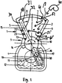
- the Fig. 1 is different from the Fig. 10 in that the housing 1 in the circular-arc-shaped wall 8 has a cooling opening 51 to the chamber 2, In addition, in contrast to the embodiment of Fig. 10 provided in the side wall 6 no inlet and outlet valves. Through the cooling opening 51, a cooling fluid, in the example shown air, flows into the chamber 2 and cools it. In addition, the piston 15 is convectively cooled by the air at least on one of the working surface 30 opposite side 32.
- the piston engine of Fig. 1 is designed as eg compressor and the cooling by means of the cooling opening can increase the efficiency of the compressor.
- a second cooling opening 51 ' may be provided in the side wall 6.
- the second cooling opening is formed, for example, as a cooling fluid outlet, through which the cooling fluid can flow.
- a flow direction of the cooling fluid is indicated in the figure by means of arrows.
- the piston engine of Fig. 2 differs from the embodiment of Fig. 10 in that a cooling opening 52 is provided centrally in the arcuate wall 8. While in the execution of Fig. 1 in one revolution of the crankshaft 19 two working cycles, namely suction and compression, are possible, it is in the embodiment of Fig. 2 four work cycles. Due to the central design of the cooling opening 52, the working chamber 2 can be alternately rinsed left and right with cooling fluid. Depending on the pivotal position of the piston 15, the working chamber 2 opens or closes the working chamber 2.
- the cooling opening 52 in the circular arc-shaped wall 8 is in both the Fig. 1 as well as in the Fig. 2 Defined by a center angle ⁇ , which is smaller than a pivot angle ⁇ of the piston 15.
- the opening 51 and 52 in the arcuate wall 8 extends over an entire axial extent of the arcuate wall 8. That is, the opening 51 and 52 is formed as an elongated groove in the arcuate wall and extending from the front end wall to the rear end wall 7. Alternatively, the cooling opening 51 and 52 may also have a smaller axial extent.
- the Fig. 3 is different from the Fig. 10 in that a cooling opening 53 is arranged in the rear end wall 7. Moreover, in contrast to the execution of the Fig. 10 provided in the side wall 6 no inlet and outlet valves. Furthermore, the piston 15 has only one working surface 30.
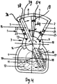
- the embodiment of the Fig. 4 differs from the embodiment of the Fig. 10 in that a cooling opening 54 is arranged centrally in the rear end wall 7. Like in the Fig. 2 Here, too, the opening 54 is arranged centrally. While the piston 15, the opening 53 of the Fig. 3 closes at a pivotal position of the piston 15 on the right side wall 6, the piston 15 closes the opening 54 at a central position of the piston 15 in the Fig. 4 , Both the opening 53 of the Fig. 3 as well as the opening 54 of the Fig. 4 extends over an entire radial extent of the end wall 7 from the bearing housing 3 to the circular arc-shaped wall 8. In both embodiments, the opening 53 and 54 in the front end wall (not shown) is provided. It may also be provided only one opening 53 and 54 in the front end wall or in the rear end wall 7.
- While the piston 15 of the FIGS. 1 and 3 has only one working surface 30, the piston 15 of the FIGS. 2 and 4 in addition to a first work surface 30, a second work surface 29.
- the cooling opening 52 and 54 of the FIGS. 2 and 4 separates a first working chamber from a second working chamber.
- the circular arc-shaped wall 8 of FIG. 2 and the end wall 7 of the FIG. 4 divided in two by the cooling opening 52 and the cooling opening 54.
- the piston engine of Fig. 5 differs from the embodiment of the Fig. 10 in that a cooling opening 55 is provided in the side wall 6. Moreover, in contrast to the execution of the Fig. 10 provided in the side wall 6 no inlet and outlet valves. As a result, the piston 15 has only one working surface 30.
- the cooling opening 55 in the side wall 6 extends over a total radial and axial extent of the side wall 6. That is, in the embodiment of Fig. 5 was dispensed with the entire side wall 6. As a result, a continuous convective cooling of the piston 15 on one of the working surface opposite side 32 is possible.
- the variable working chamber of Fig. 5 completed in each pivotal position of the piston 15.
- Fig. 6a The execution of Fig. 6a is different from the execution of Fig. 10 in that the side wall 6 is omitted altogether and that, moreover, an opening 51 is provided in the circular-arc-shaped wall 8. Moreover, in contrast to the execution of the Fig. 10 No inlet and outlet valves are provided in the side wall 6 and the piston 15 has only one working surface 30.
- the execution of Fig. 6a thus represents a mixed form of FIGS. 5 and 1
- the circular arc-shaped wall 8 of Fig. 6a defines a second center angle ⁇ of about 25 °, which is smaller than the previously described pivoting angle ⁇ of the piston 15.
- the opening 51 in the arcuate wall 8 is defined by the center angle ⁇ . In the Fig. 6a the angles ⁇ and ⁇ are equal. However, they may differ from each other in other embodiments. Thus, the center angle ⁇ may be larger or smaller than the center angle ⁇ .
- the execution of Fig. 6b is thus a hybrid form of the training of FIGS. 2 and 4 .
- the cooling opening 54 of the rear end wall 7 does not extend over an entire radial extent of the end wall 7, but approximately up to one third of the radial extent of the end wall 7.
- the cooling fluid is by means of a blower 60 through the formed as a cooling fluid inlet cooling opening 52 in the circular arc Wall 8 is inserted into the chamber 2.
- the cooling fluid is subsequently discharged from the chamber 2 through the cooling opening 54 formed as a cooling fluid outlet in the rear end wall 7.
- the flow direction of the cooling fluid is indicated by arrows.
- the chamber 2 can thus be flushed particularly well in this embodiment by means of the cooling fluid.
- a cooling opening in the front end wall (not shown) may be provided.
- a cooling opening 54 and 54 ' is provided in the rear end wall 7 and in the front end wall.
- a projection of the cooling opening 54 'of the front end wall on the rear end wall 7 is in the FIG. 6c indicated by dashed lines.
- Cooling fluid is introduced into the chamber 2 by means of an optional blower (not shown) through the cooling opening 54 formed as a cooling fluid inlet in the front end wall. After an effective rinsing and cooling of the chamber 2, the cooling fluid is subsequently discharged from the chamber 2 in the rear end wall 7 by the cooling opening 54 'designed as a cooling fluid outlet.
- the flow direction of the cooling fluid is indicated by an arrow.
- the chamber 2 can thus be flushed particularly well in this embodiment by means of the cooling fluid.
- the flow direction can also be reversed.
- a blower blows the cooling fluid into the chamber 2 through the cooling opening 54 of the rear end wall.
- the cooling fluid leaves the chamber 2 after flushing the chamber 2 through the cooling opening 54 'of the front end wall.
- variable working chamber is closed or opened depending on the pivot position of the piston.
- the piston engine of Fig. 6d differs from the embodiment of the Fig. 10 in that a cooling opening 55 is provided in the side wall 5.
- a second circular arc-shaped wall 70 is fixed, which is arranged on a smaller radius than a maximum radial extent of the piston 15 and engages in the cooling opening 55 of the side wall 5.
- the cooling opening 55 which is likewise designed as a passage for the second circular-arc-shaped wall 70, is provided above the second circular-arc-shaped wall 70 when viewed from the pivot axis 14. It can of course also be arranged below the second circular wall 70.
- a second variable working chamber is defined by the second arcuate wall 70, the piston 15, the side wall 5, the front wall and the rear wall 7 and is sealed off by these walls.
- Fig. 6d There are thus two variable working chambers which are closed in each pivotal position of the piston 15, whereby, for example, a two-stage compression is possible.
- the Figures 1-6d further differ from the FIG. 10 in that a size of the cooling openings 51, 51 ', 52, 53, 54 and 55 is in each case variably controllable or adjustable by means of a slide 61, 61', 62, 63, 64 and 65 arranged in a corresponding housing wall.
- the slide 61, 61 ', 62, 63, 64 and 65 is able to complete the chamber 2 flush and is each connected to an electronic control device, not shown, which is further connected to the piston 15, non-illustrated pressure sensor and temperature sensor is connected.
- the control device is configured to control the spool 61, 61 ', 62, 63, 64 and 65 to regulate the size of the cooling ports 51, 51', 52, 53, 54 and 55 during operation of the reciprocating engine or as needed to enlarge or reduce. From reaching a threshold value of a temperature and / or a pressure in the chamber 2, the cooling opening 51, 51 ', 52, 53, 54 and 55 for cooling the piston 15 and / or the chamber 2 can be opened or closed or its size can be increased or reduced in size. For example, when the temperature measured at the piston 15 is less than or more than a predetermined threshold, the cooling holes 51, 51 ', 52, 53, 54 and 55 may be closed or opened to increase a delivery volume of the reciprocating engine.
- the slide 61, 61 ', 62, 63, 64 and 65 may alternatively be actuated by means of a mechanical control device, for example a camshaft, to more or less close the cooling opening 51, 51', 52, 53, 54, 55 or to open.
- a mechanical control device for example a camshaft
- a throttle or other control device may be provided.
- Cooling fins 31 provided on one of the working surface 30 opposite side 32 of the piston 15 to increase the cooling. Furthermore, to improve the cooling effect in each case in the embodiments of Figures 1-6 an optional blower 60 or a cooling device provided (in the Figures 3 . 4 . 6c . 7 . 8th and 9 not shown), which blows air or another cooling fluid into the cooling opening 51, 52, 53, 54 and 55 as needed.
- the blower 60 is also connected to the said control device.
- the blower 60 is actuated by the control device, in particular, when the slide 61, 62, 63, 64 and 65 opens or closes the respective opening 51, 52, 53, 54 and 55. If no cooling device is provided, the cooling fluid can be sucked by the movement of the piston through the cooling opening 51, 52, 53, 54 and 55.
- a Venturi tube may be provided on the cooling air inlet opening shown in the figures. To increase the cooling effect may be provided on the outside of the housing cooling fins.
- FIGS. 11A, 11B and 12 Referenced.
- FIGS. 11A, 11B and 12 are views of cross sections of a piston engine according to the prior art of DE 10 2010 036 977 B3 shown, which are also included in the present application.
- Pistons 101 and 102 are connected to a rotary cylinder 106 rotatably mounted in the housing 103 about a rotation axis 104 via a bearing 105 and each have a guide groove 107 at one end, into which a crankshaft journal 108 engages a crankshaft 110 connected to a drive shaft 109.
- the guide groove 107 acts as a connecting rod loop or piston loop, which thus forms an integral part the piston 101 and 102 is.
- the two with the respective piston 101 and 102 operatively connected crankshafts 110 are, like the Fig.
- the integrally formed housing 103 comprises - indicated by a dashed line X - two, but rotated by 180 °, joined together housing parts 103a, 103b each having a substantially circular sector-shaped cross-section, in which once on the upper housing wall 111 and once on the lower housing wall 112 the Rotary cylinder 106 of the piston 101 and 102 are mounted.
- a chamber A1 and A2 enclosed by the housing thus has the form of two equal-sized, oppositely lying circular sectors.
- the housing 103 further comprises a housing rear wall 114 and a housing cover 113 and a first side wall 115 and a second side wall 116. The two in each position parallel to each other aligned double piston 101, 102 are in a starting position, as in Fig.
- the piston machine described above can also be operated as a compressor or as an expansion engine or as a combination of these.
- the medium-large working chamber A3 can operate as an expansion engine, while the two outer-small working chambers A1 and A2 operate as a compressor or as a pump and are driven by the expansion motor.
- the inner working chamber A3 and an outer (left) working chamber A1 as the first compressor stage and the other outer working chamber A2 as a second compressor stage could be operated.
- the working chambers A1, A2 and A3 can each fulfill different functions as compressor, pump or motor.
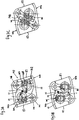
- the embodiment of the Figs. 7A-7C differs from the embodiment of the Fig. 11 in that cooling holes 151 are provided in the side walls 15 and 16, the cooling holes 151 in the side walls 115 and 116 extending over a total radial and axial extent of the side walls 115 and 116.
- the pistons 101 and 102 can be cooled by means of a cooling fluid at least convectively on each side of the piston opposite the working surface of the piston.
- the embodiments of the FIGS. 7a to 7c Incidentally, similar to the embodiment of the Fig. 5 , Instead of two cooling holes 151, as in the FIGS. 7a-c can also be seen in only one of the side walls 115 and 116, a cooling port 151 may be provided. In that case, only one piston 101, 102 is cooled.
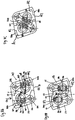
- the embodiment of the Figs. 8A-8C differs from the embodiment of the Fig. 11 in that two cooling openings 152 are provided in the circular arc-shaped wall. Like in the Fig. 11 includes the embodiment of the Fig. 8 also three working chambers A1, A2 and A3. A particularly good cooling effect can be achieved in the working chamber A3, since the cooling holes 152 are arranged opposite one another.
- a cooling fluid for example air, can thus flow in and out, for example, from one side to the other FIG. 8 indicated by arrows 130 and 131.
- the working chambers A1, A2 and A3 and the pistons 101 and 102 can thus be cooled at least convectively by means of a cooling fluid.
- the cooling opening 152 is designed to be just as large as an upper edge 140 of the pistons 101 and 102.
- the cooling opening 152 can also be smaller or larger than the upper edge 140 of the pistons 101 and 102.
- the Fig. 8c are working chambers A1 and A2 open, while in the pivot position of the Fig. 8a the working chamber A3 is largely open.
- the arrangement of the cooling holes 152 in the Fig. 8 Incidentally, the execution of the Fig. 2 , Alternatively, only one cooling opening 152 instead of two cooling openings 152 can be provided here as well.
- FIGS. 7 and 8th are mixed forms of FIGS. 7 and 8th shown, in analogy to the embodiment of the Fig. 6a .
- Fig. 9a is the circular arc in cross-section wall formed by two parts 111 'and 111 "and 112' and 112", which lie radially at different positions.
- the radial gap 140 extends in the pivoting direction over a center angle ⁇ and in the axial direction from the housing cover 113 to the housing rear wall 114.
- the dimensions of the gap 140 can be varied depending on the embodiment in the radial direction, in the axial direction or in the pivoting direction.
- the Fig. 9b is the circular arc-shaped wall 111 "and 112" only as large as the upper edge 140 of the piston 101 and 102.
- the dimensions of the circular arc wall 111 "and 112" may be smaller or larger.
- the piston 101 and 102 can be convectively cooled from several sides. A loss of chamber volume is thus in the FIGS. 9a and 9b compensated by an increased cooling effect.
- the Figures 7-9 further differ from the FIG. 11 in that a size of the cooling openings 151 and 152 is in each case variably controllable or adjustable by means of a slider, not shown, arranged in a corresponding housing wall.
- the slide is able to flush the chamber and is each connected to an electronic control device, not shown, which is further connected to the piston 101 and 102, not shown pressure sensor and temperature sensor.
- the control device is configured to control the slide to regulate or change the size of the cooling opening during operation of the reciprocating engine.
- the cooling apertures 151 and 152 may be more or less opened for cooling the piston 101 and 102 and / or the chamber.
- the slide may alternatively be actuated by means of a mechanical control device, for example a camshaft, to more or less close or open the cooling opening 151 and 152.
- a throttle or other control device may be provided.
- an optional blower or a cooling device provided (in the FIGS. 7 . 8th and 9 each not shown), which blows air or other cooling fluid into the cooling port 151 and 152 as needed.
- the fan is also connected to the mentioned control device.
- the blower is actuated by the control device, in particular, when the slide opens or closes the respective opening 151 and 152. If no cooling device is provided, the cooling fluid can be sucked by the movement of the piston through the cooling holes 151 and 152.
- a Venturi tube may be provided on the cooling air inlet opening shown in the figures. To increase the cooling effect may be provided on the outside of the housing cooling fins.
- FIGS. 7A to 9B can be extended by further side by side, but rotated by 180 ° to each other arranged housing parts with double piston plates.
- the drive or output of the piston engine is not on the illustrated embodiments of FIGS. 1 to 9B limited. It can be provided, for example, that the crank pin of the crankshaft engages in a connecting rod eye of a connecting rod pivotally connected to the piston.
- LIST OF REFERENCE NUMBERS 55 cooling opening 1 housing 60 blowers 2 working chamber 61 slides 3 bearing housing 61 'slide 4 crankcase 62 slides 5 Left sidewall 63 slides 6 right side wall 64 slides 7 front wall 65 slides 8 Circular wall 70 circular wall 9 rotary cylinder 101 piston 10 cups 102 pistons 11 crank radius 103 housing 12 ⁇ fsumpf 103a housing part 13 sealing strips 103b housing part 14 pivot axis 104 axis of rotation 15 pistons 105 bearings 16 connecting rod 106 rotary cylinder 17 guide groove 107 guide groove 18 crankpins 108 crankshaft journals 19 crankshaft 109 drive shaft 22 Left inlet valve 110 crankshaft 23 Left exhaust valve 111 housing wall 24 Right inlet valve 111 'circular arc-shaped wall 25
Landscapes
- Engineering & Computer Science (AREA)
- Mechanical Engineering (AREA)
- General Engineering & Computer Science (AREA)
- Compressor (AREA)
- Pistons, Piston Rings, And Cylinders (AREA)
- Reciprocating Pumps (AREA)
- Details Of Reciprocating Pumps (AREA)
Description
- Die Anmeldung betrifft eine Kolbenmaschine, welche ein Gehäuse mit einer Kammer, die einen im Wesentlichen kreissektorförmigen Querschnitt aufweist, einen als Schwenkelement ausgebildeten schwenkbaren und in dem Gehäuse angeordneten Kolben mit einer ersten Arbeitsfläche, wobei das Gehäuse und der Kolben mindestens eine erste variable Arbeitskammer definieren, einen mit dem Kolben verbundenen Antrieb oder Abtrieb sowie einen in der Arbeitskammer angeordneten Auslass zum Auslassen eines Arbeitsfluids aufweist.
- Kolbenmaschinen der eingangs erwähnten Art, die als Arbeitsmaschinen in Form von Kolbenpumpen und Kolbenverdichtern oder als Kraftmaschinen in Form von Verbrennungsmotoren, Druckgasmotoren oder Hydraulikmotoren zur Umsetzung von dem Arbeitsraum erzeugten Druck in Bewegung eingesetzt werden, sind aus dem Stand der Technik bekannt.
- Beispielsweise ist in der
DE 10 2008 04 05 74 A1 eine Kolbenmaschine offenbart, welche einen als Doppelschwenkplatte ausgebildeten Kolben aufweist. Der in einem etwa kreissektorförmigen Gehäuse angeordnete Kolben ist mittels eines an dieser ausgebildeten Drehzylinders verschwenkbar eingelagert und teilt das Gehäuse in zwei voneinander getrennte, jeweils mit Ein- und Auslassventilen versehene Arbeitskammern. - In der
DE 10 2010 036 977 B3 ist ebenfalls eine Kolbenmaschine offenbart. Die Kolbenmaschine ist mit zwei als Doppelschwenkplatten ausgebildeten Kolben ausgestattet. Ein Gehäuse der Kolbenmaschine ist gebildet aus zwei oder mehreren jeweils kreiszylindersegmentförmigen, jedoch um 180 Grad gedreht, einstückig aneinandergefügten, einen gemeinsamen Hohlraum bildenden Gehäuseteilen mit jedem Gehäuseteil zugeordneten, jeweils in entgegengesetzter Richtung synchron angetriebenen parallel zueinander angeordneten Kolben, die mit der jeweils benachbarten schrägen Seitenwand jeweils eine äußere Arbeitskammer und zwischen den Doppelkolbenplatten jeweils eine innere Arbeitskammer mit in einer Gehäuserückwand in Höhe einer gedachten Trennlinie zwischen den aneinander grenzenden Gehäuseteilen ausgebildeten dritten und vierten Ein- und Auslassventilen definieren. - Die Druckschriften
WO 95/08055 A1 US 3 408 991 A ,GB 486 745 A DE 37 05 313 A1 zeigen weitere Beispiele von Kolbenmaschinen. - Der Erfindung liegt die Aufgabe zugrunde, eine Kolbenmaschine der eingangs erwähnten Art so weiterzuentwickeln, dass sie mit größerer Effektivität betrieben werden kann. Die Aufgabe wird mit einer gemäß den Merkmalen des Hauptanspruchs ausgebildeten Kolbenmaschine gelöst. Zweckmäßige Weiterbildungen der Anmeldung sind Gegenstand der Unteransprüche und der Ausführungsbeispiele.
- Die Kolbenmaschine umfasst ein Gehäuse mit einer Kammer, die einen im Wesentlichen kreissektorförmigen Querschnitt aufweist, sowie einen als Schwenkelement ausgebildeten schwenkbaren und in dem Gehäuse angeordneten Kolben mit einer ersten Arbeitsfläche, wobei das Gehäuse und der Kolben mindestens eine erste variable Arbeitskammer definieren. Weiterhin umfasst die Kolbenmaschine einen mit dem Kolben verbundenen Antrieb oder Abtrieb sowie ein in der Arbeitskammer angeordnetes Auslassventil zum Auslassen eines Arbeitsfluids. Das Gehäuse weist in mindestens einer Gehäusewand eine Kühlöffnung zur Kammer auf zumindest zur konvektiven Kühlung einer der ersten Arbeitsfläche gegenüberliegenden Seite des Kolbens mittels eines Kühlfluids. Durch die Kühlöffnung kann ein Kühlfluid in die Kammer eingeführt werden, wodurch die Temperatur des Kolbens und/oder des Arbeitsfluids und/oder des Gehäuses und/oder der Kammer verringert werden kann. Hierdurch lässt sich der Wirkungsgrad der Kolbenmaschine steigern. Typischerweise wird durch die Kühlöffnung zwar ein Arbeitsvolumen der variablen Arbeitskammer verringert. Die Kolbenmaschine kann jedoch durch Kühlung mit einer größeren Effektivität betrieben werden. Je nach Lage der Kühlöffnung können neben der genannten Fläche des Kolbens z.B. auch weitere Flächen des Kolbens sowie eine oder mehrere Gehäusewände oder Teile der Kammer intensiv gekühlt werden.
- Die Kammer ist durch eine im Querschnitt kreisbogenförmige Wand begrenzt. Im Folgenden wird die im Querschnitt kreisbogenförmige Wand mit "kreisbogenförmiger Wand" bezeichnet. Die Kühlöffnung ist in der kreisbogenförmigen Wand vorgesehen. Durch die Öffnung in der kreisbogenförmigen Wand kann die Kammer mittels eines Kühlfluids gespült werden, wodurch eine effektive Kühlung der Kammer stattfinden kann. Beispielsweise können heiße Rückexpansionsgase nach Verdichtung in der Kammer durch einen Spülvorgang mittels des Kühlfluids aus der Kammer beseitigt werden. Hierdurch lässt sich der Wirkungsgrad der Kolbenmaschine weiter steigern.
- Ein Schwenkwinkel (vgl. z.B. Winkel α in den
Figuren 1-6 ) des Kolbens kann die maximale Auslenkung einer Schwenkbewegung des Kolbens von einem Totpunkt bis zum nächsten Totpunkt definieren. Vorzugsweise beträgt der Schwenkwinkel ≤ 90°, typischerweise ≤ 60°. Bevorzugt ist der Schwenkwinkel jedoch größer als 40°. Abhängig von den Druckverhältnissen können unterschiedliche Schwenkwinkel zum Einsatz kommen. Insbesondere für Dosierpumpen können auch kleinere Schwenkwinkel zum Einsatz kommen, beispielsweise ≤ 10°. - Typischerweise wird ein Mittelpunktswinkel in einem Kreis durch das Verhältnis eines Kreisbogens zum Radius r des zugehörigen Kreises angegeben. Es kann vorgesehen sein, dass die Öffnung in der kreisbogenförmigen Wand durch einen ersten Mittelpunktswinkel (vgl. z.B. Winkel β in der
Fig. 2 ) definiert ist, welcher höchstens so groß ist wie der Schwenkwinkel (α) des Kolbens. In einer Weiterbildung definiert die kreisbogenförmige Wand einen zweiten Mittelpunktswinkel (vgl. z.B. Winkel γ in derFig. 6 ), welcher z.B. höchstens so groß ist wie der Schwenkwinkel. Vorzugweise beträgt der zweite Mittelpunktswinkel weniger als 50% des Schwenkwinkels. Eine der kreisbogenförmigen Wand zugewandte Kolbenseite ist bevorzugt in einem Querschnitt kreisbogenförmig und kann einen dritten Mittelpunktswinkel (vgl. z.B. Winkel δ in derFig. 10 ) definieren. Der zweite Mittelpunktswinkel (γ) der kreisbogenförmigen Wand ist beispielsweise genau so groß wie der dritte Mittelpunktswinkel (6) der Kolbenseite. Der zweite Mittelpunktswinkel kann aber auch kleiner oder größer sein als der dritte Mittelpunktswinkel. Der erste Mittelpunktswinkel (β) kann größer oder kleiner als oder genauso groß sein wie der genannte zweite (γ) und/oder dritte Mittelpunktswinkel (δ). Die Abmessungen der genannten im Querschnitt kreisbogenförmigen Kolbenseite, der kreisbogenförmigen Wand und der Öffnung in der kreisbogenförmigen Wand können somit variiert und abgestimmt werden, je nachdem wieviel Kühlung benötigt ist oder je nachdem wie groß ein Förder- oder Arbeitsvolumen der Kolbenmaschine sein soll. - Typischerweise ist der Kolben um eine Schwenkachse schwenkbar. Die Schwenkachse kann hierbei eine axiale Richtung definieren. Senkrecht zur axialen Richtung und senkrecht zur Schwenkrichtung kann eine radiale Richtung definiert werden. Es kann z.B. vorgesehen sein, dass die Öffnung in der kreisbogenförmigen Wand sich über eine gesamte axiale Ausdehnung der kreisbogenförmigen Wand erstreckt.
- In einer Ausführung definiert eine Schwenkbewegung des Kolbens eine Schwenkebene. Die Kammer ist vorzugsweise durch eine Vorderwand und eine Rückwand begrenzt, wobei die Vorderwand und die Rückwand parallel zur Schwenkebene ausgebildet sein können. Es kann vorgesehen sein, dass die Kühlöffnung in der Vorderwand und/oder in der Rückwand ausgebildet ist. Mit dieser Ausbildung kann in ähnlicher Weise eine Kühlung erreicht werden, wie bei der oben beschriebenen Ausbildung der Kühlöffnung in der kreisbogenförmigen Wand. Die Kühlöffnung in der Rückwand und/oder Vorderwand erstreckt sich beispielsweise über eine gesamte radiale Ausdehnung der Rückwand und/oder der Vorderwand.
- Der An- oder Abtrieb umfasst typischerweise zumindest eine Kurbelwelle mit einem Kurbelzapfen. Der Kurbelzapfen greift beispielsweise in ein Pleuelauge einer mit dem Kolben verbundenen Pleuelstange oder in eine Führungsnut einer fest mit dem Kolben verbundenen Pleuelschlaufe ein. Einem Fachmann ist geläufig, dass es viele Möglichkeiten für die Konstruktion des Antriebs oder des Abtriebs gibt. Eine Drehzahl der Kurbelwelle beträgt typischerweise mehr als 1500 min-1. Die Drehzahl kann sogar bis zu 8000 min-1 oder mehr betragen.
- Die Arbeitsfläche des Kolbens ist typischerweise die Fläche des Kolbens, durch die oder an der Arbeit geleistet wird. Es kann weiter vorgesehen sein, dass der Kolben auf einer der ersten Arbeitsfläche gegenüberliegenden Seite eine zweite Arbeitsfläche aufweist und der Kolben und das Gehäuse eine zweite variable Arbeitskammer mit einem darin angeordneten zweiten Auslassventil definieren, wobei die Kühlöffnung die erste Arbeitskammer von der zweiten Arbeitskammer trennt oder zumindest auf einer Trennlinie zwischen der ersten Arbeitskammer und der zweiten Arbeitskammer liegt. Arbeit kann dann jeweils abwechselnd von der ersten Arbeitsfläche und von der zweiten Arbeitsfläche geleistet werden, je nach dem, welche variable Arbeitskammer gerade geschlossen und geöffnet ist. Die konvektive Kühlung mittels des Kühlfluids findet dann üblicherweise zumindest an der jeweils gegenüberliegenden Seite der Arbeitsfläche des Kolbens statt. Die Kühlöffnung liegt bevorzugt in der kreisbogenförmigen Wand, z.B. in der Mitte der kreisbogenförmigen Wand, und/oder in der Vorderwand und/oder in der Rückwand. Die beiden Arbeitskammern werden typischerweise während einer kompletten Schwenkbewegung oder einer Umdrehung der Kurbelwelle von 360° abwechselnd geöffnet und geschlossen. Die geöffnete Arbeitskammer wird z.B. mittels des Kühlfluids gespült, während bei der geschlossenen Arbeitskammer ein Arbeitsfluid gefördert oder komprimiert werden kann. Bei dieser Ausbildung der Kolbenmaschine lassen sich der genannte Spül- und Kühlvorgang somit besonders effektiv durchführen.
- In einer weiteren Ausbildung ist die Arbeitskammer je nach Schwenklage des Kolbens geöffnet oder geschlossen. Bei geöffneter Arbeitskammer strömt vorzugsweise das Kühlfluid in die Arbeitskammer und kühlt zumindest konvektiv die der Arbeitsfläche gegenüberliegende Seite des Kolbens und/oder spült die Arbeitskammer.
- Die Kammer kann weiterhin durch eine der ersten Arbeitsfläche abgewandte erste Seitenwand begrenzt sein, wobei die Kühlöffnung in der ersten Seitenwand vorgesehen ist. Typischerweise ist die Kammer durch eine der ersten Arbeitsfläche zugewandte zweite Seitenwand begrenzt. Ferner kann die variable Arbeitskammer durch den Kolben, die zweite Seitenwand, die kreisbogenförmige, die Vorderwand und die Rückwand begrenzt sein. Falls die Kühlöffnung lediglich in der der Arbeitsfläche abgewandten ersten Seitenwand vorgesehen ist, findet eine Spülung der Arbeitskammer mittels des Kühlfluids somit üblicherweise nicht statt. Stattdessen erlaubt diese Ausbildung eine permanente konvektive Kühlung der der Arbeitsfläche gegenüberliegenden Seite des Kolbens.
- Die Kühlöffnung in der ersten Seitenwand kann sich über eine gesamte radiale und/oder axiale Ausdehnung der Seitenwand erstrecken. Vorzugsweise erstreckt sich die Kühlöffnung sogar über die gesamte erste Seitenwand, d.h. die erste Seitenwand wird weggelassen. Hierdurch kann die Kühlwirkung weiter vergrößert werden.
- Zur Bildung der Kühlöffnung im Gehäuse können eine oder mehrere Gehäusewände ganz oder zum Teil entfernt sein, wodurch zwar ein Arbeitsvolumen der Kammer verringert wird, aber insgesamt die Arbeitsqualität der Kolbenmaschine verbessert werden kann.
- Es kann vorgesehen sein, dass die kreisbogenförmige Wand und/oder die Vorderwand und/oder die Rückwand und/oder die genannte Seitenwand durch die Kühlöffnung zweigeteilt ist/sind. Die Kühlöffnung kann insbesondere in einer Gehäusewand vorgesehen sein, wo Platz ist und eine gute Durchströmung des Kühlfluids gewährleistet ist. Die Kühlöffnung kann durch verschiedenste Formen in der Gehäusewand ausgebildet sein, wie z.B. eine Nut, einen Kreissektor oder einen Kreis oder eine andere Form. Es können auch mehrere Kühlöffnungen in jeweils verschiedenen Wänden vorgesehen sein, z.B. in der kreisbogenförmigen Wand und/oder der Vorderwand und/oder der Rückwand und/oder der Seitenwand. Die genannten Kühlöffnungen können miteinander kombiniert werden,
- Falls mehrere Kühlöffnungen vorgesehen sind, kann eine Kühlöffnung als Kühlfluideinlass und die andere Kühlöffnung als Kühlfluidauslass ausgebildet sein. Z.B. ist in einer Ausführung eine Kühlöffnung jeweils in der Rückwand und in der Vorderwand ausgebildet. Das Kühlfluid kann z.B. durch die Kühlöffnung der Rückwand oder der Vorderwand in die Kammer eingelassen werden und durch die Kühlöffnung der Vorderwand oder der Rückwand ausgelassen werden. Weiterhin kann die Kühlöffnung auch jeweils in der kreisbogenförmigen Wand und in der Rückwand und/oder in der Vorderwand vorgesehen sein. Das Kühlfluid kann in dieser Ausbildung z.B. durch die Kühlöffnung in der kreisbogenförmigen Wand in die Kammer eingelassen werden und durch die Kühlöffnung in der Rückwand und/oder in der Vorderwand ausgelassen werden. Auch andere Kombinationen von Kühlöffnungen in jeweils verschiedenen Gehäusewänden sind denkbar, bei denen das Kühlfluid durch eine Kühlöffnung in die Kammer eingelassen wird und durch die jeweils andere Kühlöffnung aus der Kammer ausgelassen wird. Die Kammer kann in diesen Ausführungen besonders gut mittels des Kühlfluids gespült werden.
- Falls mehrere Kühlöffnungen vorgesehen sind, können diese verschieden groß oder sogar geteilt sein. Die Kühlöffnungen können anders in der Breite und in der Länge gestaltet sein.
- Als Kühlfluid oder Arbeitsfluid können z.B. Luft, CO2 oder andere Gase oder eine Flüssigkeit wie z.B. Wasser verwendet werden. Für den Fachmann ist es ersichtlich, dass die Wahl des Kühlfluids und des Arbeitsfluids von der jeweiligen Ausführungsform der Kolbenmaschine abhängt. Die Kolbenmaschine kann beispielsweise als Pumpe, Vakuumpumpe, Verdichter oder Motor betreibbar sein.
- In einer weiteren Ausführungsform kann an dem Kolben eine zweite im Querschnitt kreisbogenförmige Wand befestigt sein, welche auf einem kleineren Radius als eine maximale radiale Ausdehnung des Kolbens angeordnet ist und zumindest in einer Schwenklage des Kolbens in einen Durchlass einer Seitenwand eingreift, wobei die Kühlöffnung bevorzugt ebenfalls in dieser Seitenwand vorgesehen ist. In einer Ausführung bildet die Kühlöffnung den Einlass für die zweite im Querschnitt kreisbogenförmige Wand. Die in der Seitenwand vorgesehene Kühlöffnung kann von der Schwenkachse aus gesehen oberhalb oder unterhalb der zweiten kreisbogenförmigen Wand vorgesehen sein. Vorzugsweise wird die zweite kreisbogenförmige Wand ebenfalls durch das Kühlfluid gekühlt. Eine zweite variable Arbeitskammer kann dann zumindest durch die zweite bogenförmige Wand, den Kolben und die Seitenwand definiert sein. Mit dieser Ausführung ist beispielsweise eine zweistufige Verdichtung möglich.
- In der Arbeitskammer ist ein Einlassventil angeordnet zumindest zum Einlassen des Arbeitsfluids in die Arbeitskammer. Typischerweise unterscheidet sich die Kühlöffnung von dem Einlassventil. Typischerweise unterscheidet sich die Kühlöffnung von dem Auslassventil. Es können somit in der Arbeitskammer ein Einlass- und ein Auslassventil angeordnet sein, beispielsweise in der Rückwand, Vorderwand, Seitenwand und/oder in der kreisbogenförmigen Wand. Bei geöffneter Kammer wird die Kammer und/oder des Kolbens mittels des Kühlfluids zumindest konvektiv gekühlt und/oder gespült. Bei fortschreitender Schwenkbewegung des Kolbens schließt sich die Kammer anschließend. Das noch in der Kammer verbleibende Kühlfluid kann dann durch das Auslassventil abtransportiert werden.
- In einer weiteren Ausbildung weist der Kolben zur konvektiven Kühlung Kühlrippen auf. Vorzugsweise liegen die Kühlrippen auf der der Arbeitsfläche gegenüberliegenden Seite des Kolbens. Der Kolben kann weiterhin als Hohlkörper ausgebildet sein. Durch die Kühlrippen und/oder die Ausbildung als Hohlkörper kann die Kühlung des Kolbens weiter verbessert werden.
- In einer weiteren Ausführungsform ist eine Größe der Kühlöffnung variabel steuerbar oder einstellbar, vorzugsweise mittels eines in einer Gehäusewand angeordneten Regelorgans, oder Schiebers oder Drosselklappe. Hierdurch kann eine Größe der Öffnung gesteuert oder verkleinert oder vergrößert werden, um einen Kühlluftdurchsatz zu beeinflussen oder regulieren. Die Kolbenmaschine kann somit an unterschiedliche Leistungsanforderungen angepasst werden, wobei die Kühlwirkung während des Betriebs gesteuert werden kann. Die variabel steuerbare Kühlöffnung kann mechanisch, beispielsweise über eine Bewegung einer Nockenwelle, je nach Bedarf mehr oder weniger geöffnet oder geschlossen werden. Die variabel steuerbare Kühlöffnung kann auch durch eine elektronische Steuervorrichtung gesteuert werden, um ein eine Größe der Kühlöffnung je nach Bedarf während des Betriebs der Kolbenmaschine zu variieren. In einer weiteren Ausführung sind in der Kammer und/oder im Kolben ein Drucksensor und/oder ein Temperatursensor vorgesehen, welche mit der Steuervorrichtung und/oder einer Auswertevorrichtung verbunden sein können. Bei Erreichen eines Schwellenwerts einer Temperatur und/oder eines Drucks in der Kammer und/oder im Kolben kann die Kühlöffnung mehr oder weniger geöffnet bzw. deren Größe kann vergrößert oder verkleinert werden. Somit können während des Betriebs der Kolbenmaschine mittels der variabel steuerbaren Kühlöffnung Fördervolumen der Kolbenmaschine, Kühlfluiddurchsatz, Druck und Temperatur beeinflusst werden, um die Effizienz der Kolbenmaschine zu erhöhen.
- Das Kühlfluid kann durch die Bewegung des Kolbens durch die Kühlöffnung gesaugt werden. Ferner kann eine Kühlvorrichtung, vorzugsweise ein Gebläse oder eine Pumpe, vorgesehen sein zur Förderung des Kühlfluids durch die Öffnung des Gehäuses und in die Kammer. Die Kühlung lässt sich hierdurch noch effizienter gestalten. Um den Kühlluftdurchsatz noch weiter zu erhöhen, kann an der Kühlöffnung ein Venturirohr vorgesehen sein, welches den Durchsatz erheblich zu steigern vermag.
- Für den Fachmann ist es ersichtlich, dass mehrere Kammern hintereinander oder nebeneinander geschaltet werden können. So weist das Gehäuse zwei oder mehrere jeweils kreissektorförmige, jedoch um 180 Grad gedreht aneinandergefügte, einen gemeinsamen Hohlraum bildende Gehäuseteile auf, wobei jeweils jedem Gehäuseteil ein Kolben zugeordnet ist. Zwei benachbarte Gehäuseteile definieren dann zusammen mit ihren Kolben mindestens eine variable Arbeitskammer. Weitere Einzelheiten befinden sich z.B. in der Druckschrift
DE 10 2010 036 977 B3 . Hierbei kann in mindestens einer Kammer eine Kühlöffnung vorgesehen sein. Es können jedoch auch mehrere oder sämtliche Kammern Kühlöffnungen aufweisen. - Mit einer als Verdichter ausgebildeten Kolbenmaschine ist z.B. eine Verdichtung auf 10 bar und höher, z.B. bis 20 bar, mit einstufiger Verdichtung möglich. Weiterhin erlaubt die Kolbenmaschine eine ölfreie Funktionsweise, welche insbesondere für eine Anwendung als Vakuumpumpe, Kompressor oder Expansionsmotor erwünscht ist.
- Ausführungsbeispiele der Erfindung werden anhand beigefügter Zeichnungen näher erläutert. Es zeigen
- Fig. 1
- eine Ansicht eines Querschnitts einer Kolbenmaschine mit einer Kühlöffnung in einer kreisbogenförmigen Wand;
- Fig. 2
- eine Ansicht eines Querschnitts einer Kolbenmaschine mit einer mittig in der kreisbogenförmigen Wand gelegenen Kühlöffnung;
- Fig. 3
- eine Ansicht eines Querschnitts einer Kolbenmaschine mit einer Kühlöffnung in einer Rückwand;
- Fig. 4
- eine Ansicht eines Querschnitts einer Kolbenmaschine mit einer Kühlöffnung, welche mittig in der Rückwand vorgesehen ist;
- Fig. 5
- eine Ansicht eines Querschnitts einer Kolbenmaschine mit einer Kühlöffnung in einer Seitenwand;
- Fign. 6a bis 6c
- Ansichten eines Querschnitts einer Kolbenmaschine mit zwei Kühlöffnungen in verschiedenen Wänden;
- Fig. 6d
- eine Ansicht eines Querschnitts einer Kolbenmaschine mit einer am Kolben befestigen zweiten im Querschnitt kreisbogenförmigen Wand;
- Fign. 7a bis 7c
- eine Ansicht eines Querschnitts einer Kolbenmaschine mit zwei in einem gemeinsamen Gehäuse angeordneten Kolben, wobei in jeder Seitenwand des Gehäuses eine Kühlöffnung vorgesehen;
- Fign. 8a bis 8c
- eine Ansicht eines Querschnitts einer Kolbenmaschine mit zwei in einem gemeinsamen Gehäuse angeordneten Kolben, wobei in jeweils einer kreisbogenförmigen Wand eine Öffnung vorgesehen ist;
- Fgn. 9a-9b
- eine Ansicht eines Querschnitts von zwei Kolbenmaschinen mit jeweils zwei in einem gemeinsamen Gehäuse angeordneten Kolben, wobei in jeder Seitenwand und in jeder kreisbogenförmigen Wand eine Kühlöffnung vorgesehen ist;
- Fig. 10
- eine Ansicht eines Querschnitts einer Kolbenmaschine gemäß dem Stand der Technik;
- Fign. 11a und 11b
- eine Ansicht eines Querschnitts einer weiteren Kolbenmaschine gemäß dem Stand der Technik und
- Fig. 12
- eine Seitenansicht eines Querschnitts der mit einem Antrieb dargestellten Kolbenmaschine gemäß der
Fig. 11 . - In den Figuren werden wiederkehrende Merkmale mit den gleichen Bezugszeichen versehen. Die Kolbenmaschinen der
Figuren 1-7c sowie 10-12 sind nicht im Schutzumfang des Anspruchs 1 enthalten. - Nachfolgend wird zunächst auf die
Fig. 10 Bezug genommen. In derFig. 10 ist eine Kolbenmaschine gemäß dem Stand der Technik derDE 10 2008 040 574 A1 gezeigt, die zum Bestandteil der vorliegenden Anmeldung gemacht wird. - Wie die
Fig. 10 zeigt, umfasst die Kolbenmaschine ein Gehäuse 1, das eine Kammer 2, ein Lagergehäuse 3 und ein Kurbelgehäuse 4 einschließt. Die Kammer 2 weist einen kreissektorförmigen Querschnitt auf und wird entsprechend der Form eines Zylindersektors durch zwei im Winkel α von etwa 53° zueinander angeordnete Seitenwände 5, 6 einer vorderen Stirnwand (nicht dargestellt) und einer hinteren Stirnwand 7 sowie einer im Querschnitt kreisbogenförmigen Wand 8 und einen Drehzylinder 9 begrenzt. An die der kreisbogenförmigen Wand 8 gegenüberliegenden Enden der Seitenwände 5, 6 schließt sich ein von zwei gegenüberliegenden Lagerschalen gebildetes Lagergehäuse 3 an. Weiterhin ist ein teilweise mit einem Ölsumpf 12 gefülltes Kurbelgehäuse 4 vorgesehen. In dem Lagergehäuse 3 ist der um eine Drehachse 14 drehbare Drehzylinder 9 gelagert. Die Kammer 2 ist gegenüber dem Kurbelgehäuse 4 hermetisch, beispielsweise mit in das Lagergehäuse 3 integrierten Dichtleisten 13, abgedichtet. An dem Drehzylinder 9 sind einander diametral gegenüberliegend ein als Schwenkplatte ausgebildeter Kolben 15 und eine Pleuelstange 16 starr befestigt oder einstückig angeformt. Die Pleuelstange 16 weist eine sich über deren gesamte Länge erstreckende Führungsnut 17 auf, in die ein Kurbelzapfen 18 einer in dem Kurbelgehäuse 4 drehbar gelagerten Kurbelwelle 19 eingreift. Der typischerweise als Hohlkörper ausgebildete Kolben 15 befindet sich in der Arbeitskammer 2 und liegt abdichtend mit einer Oberkante 28 an einer Innenfläche der gewölbten kreisbogenförmigen Wand 8 an. Die Oberkante 28 des Kolbens 15 ist im Querschnitt kreisbogenförmig und wird durch einen Mittelpunktswinkel δ von etwa 8° definiert. In beiden Seitenwänden 5, 6 der Kammer 2 sind jeweils Einlassventile 22, 24 und Auslassventile 23, 25 ausgebildet. Eine Schwenkbewegung des Kolbens 15 definiert eine Schwenkebene, wobei die hintere Stirnwand 7 und die vordere Stirnwand parallel zur Schwenkebene sind. Selbstverständlich können die genannten Winkel α und 6 auch größer oder kleiner als im gezeigten Beispiel sein. - Die zuvor beschriebene Kolbenmaschine kann wie folgt als Kolbenpumpe oder als Kolbenverdichter arbeiten, aber auch als hier in der Funktion nicht beschriebener Verbrennungsmotor mit innerer oder äußerer Verbrennung fungieren: Während einer Drehbewegung einer Kurbelwelle 19 gleitet ein sich auf einen Kurbelradius 11 bewegender Kurbelzapfen 18 in einer Führungsnut 17 einer Pleuelstange 16. Diese überträgt dabei eine Schwenkbewegung auf den Kolben 15. Bei einer Schwenkbewegung des Kolbens 15 von der in der
Fig. 10 gezeigten Position an der linken Seitenwand 5 der Kammer 2 zur rechten Seitenwand 6 sind das linke Einlassventil 22 und das rechte Auslassventil 25 geöffnet, während das linke Auslassventil 23 und das rechte Einlassventil 24 geschlossen sind. Ein zuvor angesaugtes Fluid wird somit aus der Kammer 2 über das rechte Auslassventil 25 ausgestoßen. Auf der anderen Seite wird über das linke Einlassventil 22 ein Arbeitsfluid angesaugt, das bei weiterer Drehbewegung der Kurbelwelle 19 bei geschlossenem linken Einlassventil 22 und offenem linken Auslassventil 23 wieder ausgestoßen wird, während auf der rechten Seite Fluid angesaugt wird über Einlassventil 24. - Der Kolben 15 arbeitet somit als Doppelkolben mit zwei Arbeitsflächen 29 und 30, der bei einer Umdrehung der Kurbelwelle 19 zwei Schwenkbewegungen, das heißt vom linken Totpunkt an der linken Seitenwand 5 zum rechten Totpunkt an der rechten Seitenwand 6 und zurück, ausführt. Der Ölsumpf 12 übernimmt die Schmierung des Kurbelgetriebes, das heißt der Führungsnut 17 und des in dieser gleitenden Kurbelzapfens 18, der im Übrigen auch mit Wälzlagern und Kulissensteinen ausgebildet sein kann.
- Wie aus der
DE 10 2008 040 574 A1 bekannt ist, kann die Führungsnut 17 auch in dem Kolben 15 angeordnet sein. Hiermit ist eine sehr kompakte Bauweise möglich. - Es kann alternativ auch vorgesehen sein, dass der Kurbelzapfen 18 der Kurbelwelle 19 in ein Pleuelauge einer gelenkig mit dem Kolben 15 verbundenen Pleuelstange eingreift. Der Antrieb oder Abtrieb der Kolbenmaschine ist somit nicht auf die dargestellten Ausführungsformen beschränkt.
- Die
Fig. 1 unterscheidet sich von derFig. 10 dadurch, dass das Gehäuse 1 in der kreisbogenförmigen Wand 8 eine Kühlöffnung 51 zur Kammer 2 aufweist, Außerdem sind im Gegensatz zu der Ausführung derFig. 10 in der Seitenwand 6 keine Ein- und Auslassventile vorgesehen. Durch die Kühlöffnung 51 strömt ein Kühlfluid, im gezeigten Beispiel Luft, in die Kammer 2 und kühlt diese. Außerdem wird der Kolben 15 durch die Luft zumindest an einer der Arbeitsfläche 30 gegenüberliegenden Seite 32 konvektiv gekühlt. Die Kolbenmaschine derFig. 1 ist als z.B. Verdichter ausgebildet und die Kühlung mittels der Kühlöffnung vermag den Wirkungsgrad des Verdichters zu erhöhen. Optional kann, wie in derFigur 1 dargestellt, eine zweite Kühlöffnung 51' in der Seitenwand 6 vorgesehen sein. Die zweite Kühlöffnung ist z.B. als Kühlfluidauslass ausgebildet, durch den das Kühlfluid ausströmen kann. Eine Strömungsrichtung des Kühlfluids ist in der Figur mittels Pfeile angedeutet. Hierdurch kann der Spülvorgang sowie der Kühlvorgang verbessert werden. - Die Kolbenmaschine der
Fig. 2 unterscheidet sich von dem Ausführungsbeispiel derFig. 10 darin, dass eine Kühlöffnung 52 mittig in der kreisbogenförmigen Wand 8 vorgesehen ist. Während bei der Ausführung derFig. 1 bei einer Umdrehung der Kurbelwelle 19 zwei Arbeitstakte, nämlich Ansaugen und Verdichten, möglich sind, sind es bei der Ausführungsform derFig. 2 vier Arbeitstakte. Durch die mittige Ausbildung der Kühlöffnung 52 kann die Arbeitskammer 2 abwechselnd links und rechts mit Kühlfluid gespült werden. Je nach Schwenklage des Kolbens 15 öffnet sich die Arbeitskammer 2 oder schließt sich die Arbeitskammer 2. Die Kühlöffnung 52 in der kreisbogenförmigen Wand 8 ist sowohl in derFig. 1 als auch in derFig. 2 durch einen Mittelpunktswinkel β definiert, welcher kleiner ist als ein Schwenkwinkel α des Kolbens 15. In denFign. 1 und2 erstreckt sich die Öffnung 51 und 52 in der kreisbogenförmigen Wand 8 über eine gesamte axiale Ausdehnung der kreisbogenförmigen Wand 8. Das heißt, die Öffnung 51 und 52 ist als längliche Nut in der kreisbogenförmigen Wand ausgebildet und erstreckt sich von der vorderen Stirnwand bis zur hinteren Stirnwand 7. Alternativ kann die Kühlöffnung 51 und 52 auch eine kleinere axiale Ausdehnung aufweisen. - Die
Fig. 3 unterscheidet sich von derFig. 10 dadurch, dass eine Kühlöffnung 53 in der hinteren Stirnwand 7 angeordnet ist. Außerdem sind im Gegensatz zu der Ausführung derFig. 10 in der Seitenwand 6 keine Ein- und Auslassventile vorgesehen. Weiterhin weist der Kolben 15 lediglich eine Arbeitsfläche 30 auf. - Die Ausführungsform der
Fig. 4 unterscheidet sich von der Ausführungsform derFig. 10 darin, dass eine Kühlöffnung 54 mittig in der hinteren Stirnwand 7 angeordnet ist. Wie in derFig. 2 ist auch hier die Öffnung 54 mittig angeordnet. Während der Kolben 15 die Öffnung 53 derFig. 3 bei einer Schwenklage des Kolbens 15 an der rechten Seitenwand 6 schließt, schließt der Kolben 15 die Öffnung 54 bei einer mittigen Position des Kolbens 15 in derFig. 4 . Sowohl die Öffnung 53 derFig. 3 als auch die Öffnung 54 derFig. 4 erstreckt sich über eine gesamte radiale Ausdehnung der Stirnwand 7 vom Lagergehäuse 3 bis zur kreisbogenförmigen Wand 8. In beiden Ausführungen ist die Öffnung 53 und 54 auch in der vorderen Stirnwand (nicht dargestellt) vorgesehen. Es kann auch nur eine Öffnung 53 und 54 in der vorderen Stirnwand oder in der hinteren Stirnwand 7 vorgesehen sein. - Während der Kolben 15 der
Fign. 1 und3 lediglich eine Arbeitsfläche 30 aufweist, umfasst der Kolben 15 derFign. 2 und4 neben einer ersten Arbeitsfläche 30 eine zweite Arbeitsfläche 29. Die Kühlöffnung 52 und 54 derFign. 2 und4 trennt eine erste Arbeitskammer von einer zweiten Arbeitskammer. Außerdem sind die kreisbogenförmige Wand 8 derFigur 2 sowie die Stirnwand 7 derFigur 4 durch die Kühlöffnung 52 bzw. Kühlöffnung 54 zweigeteilt. - Die Kolbenmaschine der
Fig. 5 unterscheidet sich von der Ausführungsform derFig. 10 dadurch, dass eine Kühlöffnung 55 in der Seitenwand 6 vorgesehen ist. Außerdem sind im Gegensatz zu der Ausführung derFig. 10 in der Seitenwand 6 keine Ein- und Auslassventile vorgesehen. Hierdurch weist der Kolben 15 lediglich eine Arbeitsfläche 30 auf. Die Kühlöffnung 55 in der Seitenwand 6 erstreckt sich über eine gesamte radiale und axiale Ausdehnung der Seitenwand 6. D.h., in der Ausführung derFig. 5 wurde auf die gesamte Seitenwand 6 verzichtet. Hierdurch ist eine stetige konvektive Kühlung des Kolbens 15 an einer der Arbeitsfläche gegenüberliegenden Seite 32 möglich. Im Gegensatz zu denFign. 1 bis 4 ist die variable Arbeitskammer derFig. 5 in jeder Schwenklage des Kolbens 15 abgeschlossen. - Die Ausführung der
Fig. 6a unterscheidet sich von der Ausführung derFig. 10 dadurch, dass die Seitenwand 6 gänzlich weggelassen ist und dass außerdem eine Öffnung 51 in der kreisbogenförmigen Wand 8 vorgesehen ist. Außerdem sind im Gegensatz zu der Ausführung derFig. 10 in der Seitenwand 6 keine Ein- und Auslassventile vorgesehen und weist der Kolben 15 lediglich eine Arbeitsfläche 30 auf. Die Ausführung derFig. 6a stellt somit eine Mischform derFign. 5 und1 dar. Die kreisbogenförmige Wand 8 derFig. 6a definiert einen zweiten Mittelpunktswinkel γ von etwa 25°, welcher kleiner ist als der zuvor beschriebene Schwenkwinkel α des Kolbens 15. Die Öffnung 51 in der kreisbogenförmigen Wand 8 ist durch den Mittelpunktswinkel β definiert. In derFig. 6a sind die Winkel β und γ gleich groß. Sie können aber in anderen Ausführungsformen auch voneinander abweichen. So kann der Mittelpunktswinkel β größer oder auch kleiner als der Mittelpunktswinkel γ sein. - In der Ausführung der
Fig. 6b ist jeweils eine Kühlöffnung 52 und 54 in der kreisbogenförmigen Wand 8 und in der hinteren Stirnwand 7 vorgesehen. Die Ausführung derFig. 6b ist somit eine Mischform der Ausbildungen derFign. 2 und4 . Im Gegensatz zu der Ausführungsform derFig. 4 erstreckt sich die Kühlöffnung 54 der hinteren Stirnwand 7 jedoch nicht über eine gesamte radiale Ausdehnung der Stirnwand 7, sondern etwa bis zu einem Drittel der radialen Ausdehnung der Stirnwand 7. Das Kühlfluid wird mittels eines Gebläses 60 durch die als Kühlfluideinlass ausgebildete Kühlöffnung 52 in der kreisbogenförmigen Wand 8 in die Kammer 2 eingelassen. Nach einer effektiven Spülung der Kammer 2 wird das Kühlfluid anschließend durch die als Kühlfluidauslass ausgebildete Kühlöffnung 54 in der hinteren Stirnwand 7 aus der Kammer 2 ausgelassen. Hierbei ist die Strömungsrichtung des Kühlfluids durch Pfeile angedeutet. Die Kammer 2 kann somit in dieser Ausführung besonders gut mittels des Kühlfluids gespült werden. Zusätzlich kann eine Kühlöffnung in der vorderen Stirnwand (nicht dargestellt) vorgesehen sein. - In der Ausführung der
Fig. 6c ist jeweils eine Kühlöffnung 54 und 54' in der hinteren Stirnwand 7 und in der vorderen Stirnwand vorgesehen. Eine Projektion der Kühlöffnung 54' der vorderen Stirnwand auf die hintere Stirnwand 7 ist in derFigur 6c durch gestrichelte Linien angedeutet. In ähnlicher Weise zu der Ausführung derFig. 6b wird Kühlfluid mittels eines optionalen Gebläses (nicht dargestellt) durch die als Kühlfluideinlass ausgebildete Kühlöffnung 54 in der vorderen Stirnwand in die Kammer 2 eingelassen. Nach einer effektiven Spülung und Kühlung der Kammer 2 wird das Kühlfluid anschließend durch die als Kühlfluidauslass ausgebildete Kühlöffnung 54' in der hinteren Stirnwand 7 aus der Kammer 2 ausgelassen. Hierbei ist die Strömungsrichtung des Kühlfluids durch einen Pfeil angedeutet. Die Kammer 2 kann somit in dieser Ausführung besonders gut mittels des Kühlfluids gespült werden. Selbstverständlich kann die Strömungsrichtung auch umgedreht werden. In diesem Fall bläst ein Gebläse das Kühlfluid durch die Kühlöffnung 54 der hinteren Stirnwand in die Kammer 2 hinein. Das Kühlfluid verlässt die Kammer 2 nach Spülung der Kammer 2 durch die Kühlöffnung 54' der vorderen Stirnwand. - Wie aus den
Figuren 1 ,2 ,4 und6 hervorgeht, ist die variable Arbeitskammer je nach Schwenklage des Kolbens geschlossen oder geöffnet. - Die Kolbenmaschine der
Fig. 6d unterscheidet sich von der Ausführungsform derFig. 10 dadurch, dass eine Kühlöffnung 55 in der Seitenwand 5 vorgesehen ist. Außerdem ist am Kolben 15 eine zweite im Querschnitt kreisbogenförmige Wand 70 befestigt, welche auf einem kleineren Radius als eine maximale radiale Ausdehnung des Kolbens 15 angeordnet ist und in die Kühlöffnung 55 der Seitenwand 5 eingreift. Hierdurch wird eine stetige konvexe Kühlung der zweiten kreisbogenförmigen Wand bewirkt. Die ebenfalls als Durchlass für die zweite kreisbogenförmige Wand 70 ausgebildete Kühlöffnung 55 ist von der Schwenkachse 14 aus gesehen oberhalb der zweiten kreisbogenförmigen Wand 70 vorgesehen. Sie kann selbstverständlich auch unterhalb der zweiten kreisbogenförmigen Wand 70 angeordnet sein. Eine zweite variable Arbeitskammer ist durch die zweite kreisbogenförmige Wand 70, den Kolben 15, die Seitenwand 5, die Vorderwand und die Rückwand 7 definiert und wird durch diese Wände abdichtend abgeschlossen. In der Ausführung derFig. 6d gibt es somit zwei variable Arbeitskammern, die in jeder Schwenklage des Kolbens 15 geschlossen sind, wodurch z.B. eine zweistufige Verdichtung möglich ist. - Die
Figuren 1-6d unterscheiden sich des Weiteren von derFigur 10 dadurch, dass eine Größe der Kühlöffnungen 51, 51', 52, 53, 54 und 55 jeweils mittels eines in einer entsprechenden Gehäusewand angeordneten Schiebers 61, 61', 62, 63, 64 und 65 variabel steuerbar oder einstellbar ist. Der Schieber 61, 61', 62, 63, 64 und 65 vermag die Kammer 2 bündig abzuschließen und ist jeweils mit einer nicht dargestellten elektronischen Steuervorrichtung verbunden, welche weiterhin mit im Kolben 15 angeordneten, nicht-dargestellten Drucksensor und Temperatursensor verbunden ist. Die Steuervorrichtung ist dazu ausgestaltet, den Schieber 61, 61', 62, 63, 64 und 65 anzusteuern, um die Größe der Kühlöffnung 51, 51', 52, 53, 54 und 55 während des Betriebs der Kolbenmaschine zu regulieren oder je nach Bedarf zu vergrößern oder zu verkleinern. Ab dem Erreichen eines Schwellenwerts einer Temperatur und/oder eines Drucks in der Kammer 2 kann die Kühlöffnung 51, 51', 52, 53, 54 und 55 zur Kühlung des Kolbens 15 und/oder der Kammer 2 geöffnet oder geschlossen oder deren Größe kann vergrößert oder verkleinert werden. Wenn die am Kolben 15 gemessene Temperatur z.B. weniger oder mehr als ein bestimmter Schwellenwert beträgt, kann die Kühlöffnung 51, 51', 52, 53, 54 und 55 geschlossen oder geöffnet werden, um ein Fördervolumen der Kolbenmaschine zu erhöhen. Somit können während des Betriebs der Kolbenmaschine Fördervolumen, Kühlfluiddurchsatz, Druck und Temperatur beeinflusst werden, um die Effizienz der Kolbenmaschine zu erhöhen. Der Schieber 61, 61', 62, 63, 64 und 65 kann alternativ auch mittels einer mechanischen Steuervorrichtung betätigt werden, beispielsweise einer Nockenwelle, um die Kühlöffnung 51, 51', 52, 53, 54, 55 mehr oder weniger weit zu schließen oder zu öffnen. Statt des Schiebers 61, 61', 62, 63, 64 und 65 kann z.B. auch eine Drosselklappe oder eine andere Regeleinrichtung vorgesehen sein. - Anders als bei der Kolbenmaschine der
Figur 10 sind in den Ausführungsformen derFiguren 1 ,3 ,5 ,6a und6d Kühlrippen 31 auf einer der Arbeitsfläche 30 gegenüberliegenden Seite 32 des Kolbens 15 zur Erhöhung der Kühlung vorgesehen. Weiterhin ist zur Verbesserung der Kühlwirkung jeweils in den Ausführungsbeispielen derFiguren 1-6 ein optionales Gebläse 60 oder eine Kühlvorrichtung vorgesehen (in denFiguren 3 ,4 ,6c ,7 ,8 und9 jeweils nicht dargestellt), welches je nach Bedarf Luft oder ein anderes Kühlfluid in die Kühlöffnung 51, 52, 53, 54 und 55 hineinbläst. Auch das Gebläse 60 ist mit der genannten Steuervorrichtung verbunden. Das Gebläse 60 wird insbesondere dann durch die Steuervorrichtung angesteuert, wenn der Schieber 61, 62, 63, 64 und 65 die jeweilige Öffnung 51, 52, 53, 54 und 55 öffnet oder schließt. Falls keine Kühlvorrichtung vorgesehen ist, kann das Kühlfluid durch die Bewegung des Kolbens durch die Kühlöffnung51, 52, 53, 54 und 55 angesaugt werden. Um den Kühlluftdurchsatz weiter zu erhöhen, kann an der in den Figuren gezeigten Kühllufteinlassöffnung ein Venturirohr vorgesehen sein. Zur Steigerung der Kühlwirkung können auf der Außenseite des Gehäuses Kühlrippen vorgesehen sein. - Nachfolgend wird auf die
Fign. 11A, 11B und12 Bezug genommen. In denFign. 11A, 11B und12 sind Ansichten von Querschnitten einer Kolbenmaschine gemäß dem Stand der Technik derDE 10 2010 036 977 B3 gezeigt, die ebenfalls zum Bestandteil der vorliegenden Anmeldung gemacht werden. - Gemäß den
Fign. 11A, 11B und12 sind Kolben 101 und 102 mit einem im Gehäuse 103 um eine Drehachse 104 über ein Lager 105 drehbar gelagerten Drehzylinder 106 verbunden und weisen an einer Stirnseite jeweils eine Führungsnut 107 auf, in die ein Kurbelwellenzapfen 108 einer mit einer Antriebswelle 109 verbundenen Kurbelwelle 110 eingreift. Die Führungsnut 107 fungiert als Pleuelschlaufe oder Kolbenschlaufe, die somit integraler Bestandteil der Kolben 101 und 102 ist. Die beiden mit dem jeweiligen Kolben 101 und 102 in Wirkverbindung stehenden Kurbelwellen 110 sind, wie dieFig. 12 zeigt, über ein Zahnradgetriebe 126 miteinander verbunden und synchronisiert, so dass die Kolben 101, 102 synchron und in jeweils parallel entgegengesetzter Richtung angetrieben und in den in Form eines Zylindersektors (Tortenstück) ausgebildeten Gehäuseteilen 103a und 103b bewegt werden können. - Das einstückig ausgebildete Gehäuse 103 umfasst - angedeutet durch eine gestrichelte Linie X - zwei, jedoch um 180° gedrehte, aneinandergefügte Gehäuseteile 103a, 103b mit jeweils im Wesentlichen kreissektorförmigen Querschnitt, in denen einmal an der oberen Gehäusewand 111 und einmal an der unteren Gehäusewand 112 die Drehzylinder 106 der Kolben 101 und 102 gelagert sind. Eine von dem Gehäuse umschlossene Kammer A1 und A2 hat somit die Form von zwei gleich großen entgegengesetzt nebeneinander liegenden Kreissektoren. Das Gehäuse 103 umfasst weiterhin eine Gehäuserückwand 114 und einen Gehäusedeckel 113 sowie eine erste Seitenwand 115 und eine zweite Seitenwand 116. Die beiden in jeder Position parallel zueinander ausgerichteten Doppelkolben 101, 102 liegen in einer Ausgangsstellung, wie in der
Fig. 11A gezeigt, an der jeweiligen Seitenwand 115, 116 und stoßen in der Entstellung an der Trennlinie X nahezu mit einem definierten Spalt aneinander. In den beiden Seitenwänden 115 und 116 und in der Gehäuserückwand 114 in Höhe der Trennlinie X sind Einlassventile 18a, 18b und 18c sowie Auslassventile 19a, 19b und 19c angeordnet. Durch eine synchrone, aber entgegengesetzt gerichtete Drehbewegung der beiden Kurbelwellenzapfen 108 gemäß Pfeil 17a, 17b werden die beiden Kolben 101 und 102 bis nahe an die Trennlinie X aufeinander zu bewegt und bis nahe an die Seitenwände 115 und 116 voneinander weg bewegt. Es kann auch nur eine Kurbelwelle zum Einsatz kommen, wobei die Kolben 101 und 102 z.B. über ein Zahnrad synchronisiert werden. Die so ausgebildete Kolbenmaschine gemäß derFig. 11 kann z.B. als Verdichter, Pumpe oder als Motor betrieben werden. - Beispielsweise bei der Funktion als Pumpe wird ein in der inneren großen Arbeitskammer A3 zwischen den beiden Doppelkolbenplatten 101 und 102 befindliches, zuvor über das Einlassventil 18c angesaugtes Fördermedium während der Schwenkbewegung der Doppelkolbenplatten 101 und 102 in Richtung der Trennlinie X gemäß wieder aus der Arbeitskammer A3 ausgestoßen. Während dieser Schwenkbewegung (Ausstoßen) wird gleichzeitig über die Einlassventile 18a und 18b ein Fördermedium in die beiden äußeren (kleinen), sich jeweils zwischen den Doppelkolbenplatten 101 und 102 und den Seitenwänden 115 und 116 bildenden Arbeitskammern A1 und A2 gesaugt. Bei der anschließenden Bewegung der beiden Doppelkolbenplatten 101 und 102 in Richtung der Seitenwände 115 und 116 wird das zuvor in den Arbeitskammern A1, A2 angesaugte Fördermedium durch die Auslassventile 19a, 19b ausgestoßen und gleichzeitig wird Fördermedium über das Einlassventil 18c in die große Arbeitskammer A3 gesaugt. Auf diese Weise ist mit zwei zusammenwirkenden Doppelkolbenplatten 101 und 102 und drei Arbeitskammern A1, A2 und A3 in ein und demselben Gehäuse 103 ein effektiver Förderbetrieb gewährleistet. Das Maximalvolumen der beiden kleinen äußeren Arbeitskammern A1 und A2 entspricht dem Maximalvolumen der großen, inneren Arbeitskammer A3. Mit gleichermaßen hoher Effektivität kann die oben beschriebene Kolbenmaschine auch als Verdichter oder als Expansionsmotor oder als Kombination von diesen betrieben werden. Beispielsweise kann die mittlere - große - Arbeitskammer A3 als Expansionsmotor arbeiten, während die beiden äußeren - kleinen - Arbeitskammern A1 und A2 als Verdichter oder als Pumpe arbeiten und von dem Expansionsmotor angetrieben werden. Beim Einsatz der beschriebenen Kolbenpumpe als Verdichter könnten die innere Arbeitskammer A3 und eine äußere (linke) Arbeitskammer A1 als erste Verdichterstufe und die andere äußere Arbeitskammer A2 als zweite Verdichterstufe betrieben werden. Somit können die Arbeitskammern A1, A2 und A3 jeweils unterschiedliche Funktionen als Verdichter, Pumpe oder Motor erfüllen.
- Die Ausführungsform der
Fig. 7A-7C unterscheidet sich von der Ausführungsform derFig. 11 dadurch, dass Kühlöffnungen 151 in den Seitenwänden 15 und 16 vorgesehen sind, wobei die Kühlöffnungen 151 in den Seitenwänden 115 und 116 sich über eine gesamte radiale und axiale Ausdehnung der Seitenwände 115 und 116 erstrecken. Durch die Kühlöffnungen 151 können die Kolben 101 und 102 jeweils an einer der Arbeitsfläche des Kolbens gegenüberliegenden Seite des Kolbens mittels eines Kühlfluids zumindest konvektiv gekühlt werden. Die Ausführungsformen derFign. 7a bis 7c ähneln im Übrigen der Ausführungsform derFig. 5 . Statt zwei Kühlöffnungen 151, wie in denFign. 7a-c zu erkennen ist, kann auch in lediglich einer der Seitenwände 115 und 116 eine Kühlöffnung 151 vorgesehen sein. In dem Fall wird nur ein Kolben 101, 102 gekühlt. - Die Ausführungsform der
Fig. 8A-8C unterscheidet sich von der Ausführungsform derFig. 11 dadurch, dass zwei Kühlöffnungen 152 in der kreisbogenförmigen Wand vorgesehen sind. Wie in derFig. 11 umfasst die Ausführungsform derFig. 8 auch drei Arbeitskammern A1, A2 und A3. Eine besonders gute Kühlwirkung kann bei der Arbeitskammer A3 erzielt werden, da die Kühlöffnungen 152 einander gegenüberliegend angeordnet sind. Ein Kühlfluid, beispielsweise Luft, kann somit z.B. von der einen bis zur anderen Seite herein- und herausströmen, was in derFigur 8 mittels Pfeilen 130 und 131 angedeutet ist. Durch die Kühlöffnungen 152 können die Arbeitskammern A1, A2 und A3 sowie die Kolben 101 und 102 somit zumindest konvektiv mittels eines Kühlfluids gekühlt werden. Die Kühlöffnung 152 ist hierbei genauso groß ausgebildet wie eine Oberkante 140 der Kolben 101 und 102. Die Kühlöffnung 152 kann aber auch kleiner oder größer als die Oberkante 140 der Kolben 101 und 102 sein. Wie in derFig. 8b zu erkennen ist, gibt es somit eine Schwenklage, in der sämtliche Arbeitskammern A1, A2 und A3 geschlossen sind. In der Schwenklage derFig. 8c sind Arbeitskammern A1 und A2 geöffnet, während in der Schwenklage derFig. 8a die Arbeitskammer A3 weitgehend geöffnet ist. Die Anordnung der Kühlöffnungen 152 in derFig. 8 ähnelt im Übrigen der Ausführung derFig. 2 . Alternativ kann auch hier lediglich eine Kühlöffnung 152 statt zweier Kühlöffnungen 152 vorgesehen sein. - In den
Fig. 9a und 9b sind bezüglich Kühlöffnungen 151 und 152 Mischformen derFign. 7 und8 gezeigt, in Analogie zu der Ausführungsform derFig. 6a . In derFig. 9a ist die im Querschnitt kreisbogenförmige Wand durch zwei Teile 111' und 111" bzw. 112' und 112" gebildet, welche radial auf unterschiedlichen Positionen liegen. Es gibt einen radialen Spalt 140 zwischen der Oberkante 140 des Kolbens und der kreisbogenförmigen Gehäusewand 111' und 112'. Der radiale Spalt 140 erstreckt sich in Schwenkrichtung über einen Mittelpunktswinkel ε und in axialer Richtung von dem Gehäusedeckel 113 bis zur Gehäuserückwand 114. Die Abmessungen des Spalts 140 können je nach Ausführungsform radialer Richtung, in axialer Richtung oder in Schwenkrichtung variiert werden. In derFig. 9b ist die kreisbogenförmige Wand 111" und 112" lediglich so groß wie die Oberkante 140 des Kolbens 101 und 102. Alternativ können auch die Abmessungen der kreisbogenförmigen Wand 111" und 112" kleiner oder größer sein. Im Vergleich zu der Ausführungsform derFig. 8 gibt es in denFig. 9a und 9b lediglich eine Arbeitskammer A3. In den Ausführungsformen derFign. 9a und 9b kann der Kolben 101 und 102 von mehreren Seiten konvektiv gekühlt werden. Ein Verlust an Kammervolumen wird also in denFign. 9a und 9b durch eine erhöhte Kühlwirkung kompensiert. - Die
Figuren 7-9 unterscheiden sich des Weiteren von derFigur 11 dadurch, dass eine Größe der Kühlöffnungen 151 und 152 jeweils mittels eines in einer entsprechenden Gehäusewand angeordneten, nicht dargestellten Schiebers variabel steuerbar oder einstellbar ist. Der Schieber vermag die Kammer bündig abzuschließen und ist jeweils mit einer nicht dargestellten elektronischen Steuervorrichtung verbunden, welche weiterhin mit im Kolben 101 und 102 angeordneten, nicht-dargestellten Drucksensor und Temperatursensor verbunden ist. Die Steuervorrichtung ist dazu ausgestaltet, den Schieber anzusteuern, um die Größe der Kühlöffnung während des Betriebs der Kolbenmaschine zu regulieren oder zu ändern. Ab dem Erreichen eines Schwellenwerts einer Temperatur und/oder eines Drucks in der Kammer kann die Kühlöffnung 151 und 152 zur Kühlung des Kolbens 101 und 102 und/oder der Kammer mehr oder weniger geöffnet werden. Somit können während des Betriebs der Kolbenmaschine Fördervolumen, Kühlfluiddurchsatz, Druck und Temperatur beeinflusst werden, um die Effizienz der Kolbenmaschine zu erhöhen. Der Schieber kann alternativ auch mittels einer mechanischen Steuervorrichtung betätigt werden, beispielsweise einer Nockenwelle, um die Kühlöffnung 151 und 152 mehr oder weniger weit zu schließen oder zu öffnen. Statt des Schiebers kann z.B. auch eine Drosselklappe oder eine andere Regeleinrichtung vorgesehen sein. - Weiterhin ist zur Verbesserung der Kühlwirkung jeweils in den Ausführungsbeispielen der
Figuren 7-9 ein optionales Gebläse oder eine Kühlvorrichtung vorgesehen (in denFiguren 7 ,8 und9 jeweils nicht dargestellt), welches je nach Bedarf Luft oder ein anderes Kühlfluid in die Kühlöffnung 151 und 152 hineinbläst. Auch das Gebläse ist mit der genannten Steuervorrichtung verbunden. Das Gebläse wird insbesondere dann durch die Steuervorrichtung angesteuert, wenn der Schieber die jeweilige Öffnung 151 und 152 öffnet oder schließt. Falls keine Kühlvorrichtung vorgesehen ist, kann das Kühlfluid durch die Bewegung des Kolbens durch die Kühlöffnung 151 und 152 angesaugt werden. Um den Kühlluftdurchsatz weiter zu erhöhen, kann an der in den Figuren gezeigten Kühllufteinlassöffnung ein Venturirohr vorgesehen sein. Zur Steigerung der Kühlwirkung können auf der Außenseite des Gehäuses Kühlrippen vorgesehen sein. - Die Ausführungsformen der
Figuren 7A bis 9B können durch weitere nebeneinander, jedoch um 180° gedreht zueinander angeordnete Gehäuseteile mit Doppelkolbenplatten beliebig erweitert werden. - Der Antrieb oder Abtrieb der Kolbenmaschine ist nicht auf die dargestellten Ausführungsformen der
Fign. 1 bis 9B beschränkt. Es kann z.B. vorgesehen sein, dass der Kurbelzapfen der Kurbelwelle in ein Pleuelauge einer gelenkig mit dem Kolben verbundenen Pleuelstange eingreift.Bezugszeichenliste 55 Kühlöffnung 1 Gehäuse 60 Gebläse 2 Arbeitskammer 61 Schieber 3 Lagergehäuse 61' Schieber 4 Kurbelgehäuse 62 Schieber 5 Linke Seitenwand 63 Schieber 6 Rechte Seitenwand 64 Schieber 7 Stirnwand 65 Schieber 8 Kreisbogenförmige Wand 70 kreisbogenförmige Wand 9 Drehzylinder 101 Kolben 10 Lagerschalen 102 Kolben 11 Kurbelradius 103 Gehäuse 12 Öfsumpf 103a Gehäuseteil 13 Dichtleisten 103b Gehäuseteil 14 Schwenkachse 104 Drehachse 15 Kolben 105 Lager 16 Pleuelstange 106 Drehzylinder 17 Führungsnut 107 Führungsnut 18 Kurbelzapfen 108 Kurbelwellenzapfen 19 Kurbelwelle 109 Antriebswelle 22 Linkes Einlassventil 110 Kurbelwelle 23 Linkes Auslassventil 111 Gehäusewand 24 Rechtes Einlassventil 111' kreisbogenförmige Wand 25 Rechtes Auslassventil 111" kreisbogenförmige Wand 28 Oberkante Kolben 112 Gehäusewand 29 Arbeitsfläche 112' kreisbogenförmige Wand 30 Arbeitsfläche 112"kreisbogenförmige Wand 31 Kühlrippen 113 Gehäusedeckel 32 Kolbenseite 114 Gehäuserückwand 51 Kühlöffnung 115 erste Seitenwand 51' Kühlöffnung 116 zweite Seitenwand 52 Kühlöffnung 17a Bewegung Kurbelzapfen 53 Kühlöffnung 17b Bewegung Kurbelzapfen 54 Kühlöffnung 18a Einlassventil 54' Kühlöffnung 18b Einlassventil 18c Einlassventil 160 Spalt 19a Auslassventil α Schwenkwinkel des Kolbens 19b Auslassventil β Mittelpunktswinkel 19c Auslassventil γ Mittelpunktswinkel 130 Strömungsrichtung δ Mittelpunktswinkel 131 Strömungsrichtung ε Mittelpunktswinkel 140 Oberkante Kolben A1 Arbeitskammer 151 Kühlöffnung A2 Arbeitskammer 152 Kühlöffnung A3 Arbeitskammer
Claims (14)
- Kolbenmaschine, umfassend- ein Gehäuse (103) mit einer Kammer, die einen im Wesentlichen kreissektorförmigen Querschnitt aufweist,- einen als Schwenkelement ausgebildeten schwenkbaren und in dem Gehäuse (103) angeordneten Kolben (101, 102) mit einer ersten Arbeitsfläche (29, 30),wobei das Gehäuse (103) und der Kolben (101, 102) mindestens eine erste variable Arbeitskammer (A1, A2, A3) definieren,- einen mit dem Kolben (101, 102) verbundenen Antrieb oder Abtrieb,- ein in der Arbeitskammer (A1, A2, A3) angeordnetes Auslassventil (19a, 19b, 19c) zum Auslassen eines Arbeitsfluids sowie ein in der Arbeitskammer angeordnetes Einlassventil (18a, 18b, 18c) zum Einlassen des Arbeitsfluids in die Arbeitskammer (A1, A2, A3),wobei das Gehäuse (103) zwei oder mehrere jeweils kreissektorförmige, jedoch um 180 Grad gedreht aneinandergefügte, einen gemeinsamen Hohlraum bildende Gehäuseteile (103a, 103b) aufweist, wobei jeweils jedem Gehäuseteil (103a, 103b) ein zuvor genannter Kolben (101, 102) zugeordnet ist, wobei zwei benachbarte Gehäuseteile (103a, 103b) zusammen mit ihren Kolben (101, 102) mindestens eine variable Arbeitskammer (A3) definieren, wobei zwei benachbarte Kolben (101, 102) zueinander um 180° gedreht in den jeweiligen Gehäuseteilen (103a, 103b) angeordnet sind,
dadurch gekennzeichnet, dass das Gehäuse (103) in mindestens einer Gehäusewand (111, 112) eine Kühlöffnung (152, 160) zur Kammer aufweist zur konvektiven Kühlung einer der ersten Arbeitsfläche gegenüberliegenden Seite eines der genannten Kolben (101, 102) mittels eines Kühlfluids,
wobei die zwei benachbarten Gehäuseteile jeweils eine im Querschnitt kreisbogenförmige, die Kammer begrenzende Wand (111, 112) aufweisen, und in beiden kreisbogenförmigen Wänden eine Kühlöffnung (152, 160) vorgesehen ist, wobei die Kühlöffnungen (152, 160) einander gegenüberliegend angeordnet sind, sodass das Kühlfluid von der einen bis zur anderen Seite herein- und herausströmen kann. - Kolbenmaschine nach Anspruch 1, dadurch gekennzeichnet, dass die Öffnung (152) in der kreisbogenförmigen Wand (111, 112) durch einen Mittelpunktswinkel (β) definiert ist, welcher höchstens so groß ist wie ein Schwenkwinkel (α) des Kolbens (101, 102).
- Kolbenmaschine nach einem der Ansprüche 1 oder 2, dadurch gekennzeichnet, dass die kreisbogenförmige Wand (111, 112) einen zweiten Mittelpunktswinkel (γ) definiert, wobei eine der kreisbogenförmigen Wand (111, 112) zugewandte Kolbenseite (140) im Querschnitt kreisbogenförmig ist und einen dritten Mittelpunktswinkel (δ) definiert, wobei der zweite Mittelpunktswinkel (γ) genau so groß ist wie der dritte Mittelpunktswinkel (δ) oder kleiner ist als der dritte Mittelpunktswinkel (δ).
- Kolbenmaschine nach einem der Ansprüche 1 oder 2, dadurch gekennzeichnet, dass die kreisbogenförmige Wand (111, 112) einen zweiten Mittelpunktswinkel (γ) definiert, wobei eine der kreisbogenförmigen Wand (111, 112) zugewandte Kolbenseite (140) im Querschnitt kreisbogenförmig ist und einen dritten Mittelpunktswinkel (δ) definiert, wobei der zweite Mittelpunktswinkel (γ) größer ist als der dritte Mittelpunktswinkel (δ).
- Kolbenmaschine nach einem der Ansprüche 1 bis 4, dadurch gekennzeichnet, dass die Öffnung (152) in der kreisbogenförmigen Wand (111, 112) sich über eine gesamte axiale Ausdehnung der kreisbogenförmigen wand (111, 112) erstreckt.
- Kolbenmaschine nach einem der vorangehenden Ansprüche, dadurch gekennzeichnet, dass eine Schwenkbewegung des Kolbens (101, 102) eine Schwenkebene definiert, und die Kammer durch eine Vorderwand (113) und eine Rückwand (114) begrenzt ist, wobei die Vorderwand (113) und die Rückwand (114) parallel zur Schwenkebene sind, und zusätzlich eine Kühlöffnung in der Vorderwand (113) oder in der Rückwand (114) vorgesehen ist, oder in der Vorderwand und in der Rückwand jeweils eine Kühlöffnung vorgesehen ist.
- Kolbenmaschine nach Anspruch 6, dadurch gekennzeichnet, dass die Öffnung in der Rückwand (114) und/oder Vorderwand (113) Wand sich über eine gesamte radiale Ausdehnung der Rückwand (114) und/oder Vorderwand (113) erstreckt.
- Kolbenmaschine nach einem der Ansprüche 1 bis 7, dadurch gekennzeichnet, dass der Kolben (101, 102) auf einer der ersten Arbeitsfläche gegenüberliegenden Seite eine zweite Arbeitsfläche aufweist, und der Kolben (15, 101, 102) und das Gehäuse (103) eine zweite variable Arbeitskammer (A1, A2) mit einem darin angeordneten zweiten Auslassventil (19a, 19b) definieren, wobei eine zusätzliche Kühlöffnung (152) auf einer Trennlinie zwischen der ersten Arbeitskammer (A3) und der zweiten Arbeitskammer (A1, A2) liegt.
- Kolbenmaschine nach einem der vorangehenden Ansprüche, dadurch gekennzeichnet, dass die Arbeitskammer (A1, A2, A3) je nach Schwenklage des Kolbens (101, 102) geöffnet oder geschlossen ist.
- Kolbenmaschine nach einem der vorangehenden Ansprüche, dadurch gekennzeichnet, dass die Kammer durch eine der ersten Arbeitsfläche abgewandte Seitenwand (115, 116) begrenzt ist, wobei zusätzlich eine Kühlöffnung (151) in der Seitenwand (115, 116) vorgesehen ist.
- Kolbenmaschine nach Anspruch 10, dadurch gekennzeichnet, dass die Kühlöffnung (51', 55, 151) in der Seitenwand (6, 115, 116) sich über eine gesamte radiale und/oder axiale Ausdehnung der Seitenwand (6, 115, 116) erstreckt.
- Kolbenmaschine nach einem der Ansprüche 5, 7 oder 11, dadurch gekennzeichnet, dass die kreisbogenförmige Wand (8, 111, 112) und/oder die Vorderwand (113) und/oder die Rückwand (7, 114) und/oder die Seitenwand (5, 6, 115, 116) durch die Kühlöffnung (51', 52, 54, 152) zweigeteilt ist.
- Kolbenmaschine nach einem der vorangehenden Ansprüche, dadurch gekennzeichnet, dass an dem Kolben (15) eine zweite im Querschnitt kreisbogenförmige Wand (70) befestigt ist, die auf einem kleineren Radius als eine maximale radiale Ausdehnung des Kolbens (15) angeordnet ist und zumindest in einer Schwenklage des Kolbens (15) in einen Durchlass (55) einer Seitenwand (5) eingreift, wobei eine zweite variable Arbeitskammer zumindest durch die zweite bogenförmige Wand (70), den Kolben (15) und die Seitenwand (5) definiert ist.
- Kolbenmaschine nach einem der vorangehenden Ansprüche, dadurch gekennzeichnet, dass der Kolben (101, 102) Kühlrippen aufweist und/oder
als Hohlkörper ausgebildet ist und/oder
dass eine Kühlvorrichtung, vorzugsweise ein Gebläse oder eine Pumpe, vorgesehen ist zur Förderung des Kühlfluids durch die Öffnung (151, 152, 160) des Gehäuses (103) und in die Kammer und/oder
dass eine Größe der Kühlöffnung (151, 152, 160) variabel steuerbar oder einstellbar ist, vorzugsweise mittels eines in einer Gehäusewand (111, 112, 114, 115, 116, 117) angeordneten Regelorgans oder Schiebers oder Drosselklappe.
Priority Applications (1)
| Application Number | Priority Date | Filing Date | Title |
|---|---|---|---|
| EP19205086.2A EP3660267B1 (de) | 2014-05-12 | 2015-05-12 | Kolbenmaschine |
Applications Claiming Priority (2)
| Application Number | Priority Date | Filing Date | Title |
|---|---|---|---|
| DE102014208939.5A DE102014208939A1 (de) | 2014-05-12 | 2014-05-12 | Kolbenmaschine |
| PCT/EP2015/060500 WO2015173255A1 (de) | 2014-05-12 | 2015-05-12 | Kolbenmaschine mit kühlung |
Related Child Applications (1)
| Application Number | Title | Priority Date | Filing Date |
|---|---|---|---|
| EP19205086.2A Division EP3660267B1 (de) | 2014-05-12 | 2015-05-12 | Kolbenmaschine |
Publications (2)
| Publication Number | Publication Date |
|---|---|
| EP3143258A1 EP3143258A1 (de) | 2017-03-22 |
| EP3143258B1 true EP3143258B1 (de) | 2019-10-30 |
Family
ID=53284203
Family Applications (2)
| Application Number | Title | Priority Date | Filing Date |
|---|---|---|---|
| EP15726873.1A Active EP3143258B1 (de) | 2014-05-12 | 2015-05-12 | Kolbenmaschine mit kühlung |
| EP19205086.2A Active EP3660267B1 (de) | 2014-05-12 | 2015-05-12 | Kolbenmaschine |
Family Applications After (1)
| Application Number | Title | Priority Date | Filing Date |
|---|---|---|---|
| EP19205086.2A Active EP3660267B1 (de) | 2014-05-12 | 2015-05-12 | Kolbenmaschine |
Country Status (6)
| Country | Link |
|---|---|
| US (1) | US10221850B2 (de) |
| EP (2) | EP3143258B1 (de) |
| CN (1) | CN106536856B (de) |
| DE (1) | DE102014208939A1 (de) |
| ES (2) | ES2950131T3 (de) |
| WO (1) | WO2015173255A1 (de) |
Cited By (2)
| Publication number | Priority date | Publication date | Assignee | Title |
|---|---|---|---|---|
| DE102022122759A1 (de) | 2022-05-31 | 2023-11-30 | Manfred Max Rapp | Luft-dampf-motor und dessen verwendung |
| WO2023232672A1 (de) | 2022-05-31 | 2023-12-07 | Manfred Rapp | Luft-dampf-motor und dessen verwendung |
Families Citing this family (3)
| Publication number | Priority date | Publication date | Assignee | Title |
|---|---|---|---|---|
| DE102016119985B3 (de) * | 2016-10-20 | 2018-05-17 | Nidec Gpm Gmbh | Pendelkolben-Vakuumpumpe |
| RU2700108C1 (ru) * | 2018-06-01 | 2019-09-12 | Федеральное государственное автономное образовательное учреждение высшего образования "Южно-Уральский государственный университет (национальный исследовательский университет)" ФГАОУ ВО "ЮУрГУ (НИУ)" | Лопастной двигатель |
| DE102018123409A1 (de) | 2018-09-24 | 2020-03-26 | Manfred Max Rapp | Kolbenmaschine, modulares Baukastenystem für eine Kolbenmaschine sowie Verfahren zur Herstellung einer Kolbenmaschine |
Citations (1)
| Publication number | Priority date | Publication date | Assignee | Title |
|---|---|---|---|---|
| DE102010036977B3 (de) * | 2010-08-13 | 2011-11-10 | Manfred Max Rapp | Kolbenmaschine |
Family Cites Families (14)
| Publication number | Priority date | Publication date | Assignee | Title |
|---|---|---|---|---|
| US1363423A (en) * | 1919-11-10 | 1920-12-28 | Pierre Auguste Marie Le | Rotary gas-engine |
| GB331545A (en) * | 1930-03-04 | 1930-07-04 | Paul Polizzi | Improvements in internal combustion engines of the oscillating vane type |
| GB486745A (en) * | 1937-02-23 | 1938-06-09 | Johann Haragsin | Improvements relating to internal combustion engines |
| US3408991A (en) * | 1967-07-12 | 1968-11-05 | William B Pritchett Jr | Oscillating machine |
| DE2353008A1 (de) | 1973-10-23 | 1975-04-24 | Heinrich Menge | Schwingkolbenmaschine |
| DE3705313A1 (de) * | 1987-02-19 | 1987-10-08 | Franz Josef Knott | Pendelkolbenmaschine |
| US5228414A (en) * | 1992-09-10 | 1993-07-20 | Robert D. Hall | Valveless two-stroke-cycle oscillating engine |
| KR100328600B1 (ko) * | 1993-09-16 | 2002-08-08 | 피벗탈 엔지니어링 리미티드 | 내연기관 |
| US5979163A (en) * | 1997-12-29 | 1999-11-09 | Circular Motion Controls, Inc. | Rotationally pivotal motion controller |
| AU2182299A (en) * | 1999-01-25 | 2000-08-07 | Klein, Benny | Expansion-compression engine with angularly reciprocating piston |
| DE10254162A1 (de) * | 2002-11-20 | 2004-06-03 | Renner, Bernt | Vorrichtung zum Fördern eines Fluids |
| DE102005010775B3 (de) * | 2005-02-25 | 2006-04-20 | Hüttlin, Herbert, Dr. h.c. | Schwenkkolbenmaschine |
| DE102006024321A1 (de) * | 2006-05-24 | 2007-11-29 | Mehdi Nabhani | Verbrennungsmotor |
| DE102008040574B4 (de) | 2008-07-21 | 2013-08-14 | Manfred Max Rapp | Kolbenmaschine |
-
2014
- 2014-05-12 DE DE102014208939.5A patent/DE102014208939A1/de not_active Withdrawn
-
2015
- 2015-05-12 EP EP15726873.1A patent/EP3143258B1/de active Active
- 2015-05-12 EP EP19205086.2A patent/EP3660267B1/de active Active
- 2015-05-12 US US15/309,676 patent/US10221850B2/en active Active
- 2015-05-12 ES ES19205086T patent/ES2950131T3/es active Active
- 2015-05-12 WO PCT/EP2015/060500 patent/WO2015173255A1/de not_active Ceased
- 2015-05-12 CN CN201580038189.6A patent/CN106536856B/zh active Active
- 2015-05-12 ES ES15726873T patent/ES2766473T3/es active Active
Patent Citations (1)
| Publication number | Priority date | Publication date | Assignee | Title |
|---|---|---|---|---|
| DE102010036977B3 (de) * | 2010-08-13 | 2011-11-10 | Manfred Max Rapp | Kolbenmaschine |
Cited By (3)
| Publication number | Priority date | Publication date | Assignee | Title |
|---|---|---|---|---|
| DE102022122759A1 (de) | 2022-05-31 | 2023-11-30 | Manfred Max Rapp | Luft-dampf-motor und dessen verwendung |
| WO2023232672A1 (de) | 2022-05-31 | 2023-12-07 | Manfred Rapp | Luft-dampf-motor und dessen verwendung |
| DE102022122759B4 (de) * | 2022-05-31 | 2026-02-12 | Max Rapp Motorenbau GmbH & Co. KG | Luft-dampf-motor und dessen verwendung |
Also Published As
| Publication number | Publication date |
|---|---|
| CN106536856A (zh) | 2017-03-22 |
| WO2015173255A1 (de) | 2015-11-19 |
| ES2766473T3 (es) | 2020-06-12 |
| CN106536856B (zh) | 2019-06-21 |
| DE102014208939A1 (de) | 2015-11-12 |
| ES2950131T3 (es) | 2023-10-05 |
| US20170138359A1 (en) | 2017-05-18 |
| EP3660267A1 (de) | 2020-06-03 |
| US10221850B2 (en) | 2019-03-05 |
| EP3143258A1 (de) | 2017-03-22 |
| EP3660267B1 (de) | 2023-04-26 |
Similar Documents
| Publication | Publication Date | Title |
|---|---|---|
| DE102008040574B4 (de) | Kolbenmaschine | |
| EP3660267B1 (de) | Kolbenmaschine | |
| EP2603667B1 (de) | Kolbenmaschine | |
| DE4333144C2 (de) | Kältemittelkompressor mit hin- und herbeweglichen Kolben | |
| DE923985C (de) | Kolbenkompressor fuer Luft und andere gasfoermige Medien | |
| EP1987233B1 (de) | Schwenkkolbenmaschine | |
| DE102005010775B3 (de) | Schwenkkolbenmaschine | |
| DE2332411C3 (de) | Rotationskolbenverdichter | |
| DE4011671A1 (de) | Regelbare fluegelzellenpumpe | |
| DE69800445T2 (de) | Ein- und Auslassventilvorrichtung für einen Kompressor | |
| WO2004088093A1 (de) | Drehkolbenmaschine | |
| DE3401064A1 (de) | Stroemungsmittelpumpe | |
| DE2248137B2 (de) | Kurbelschleifengetriebe für Kolbenkompressoren | |
| DE102005024751B4 (de) | Schwenkkolbenmaschine | |
| DE2613472A1 (de) | Trockenlaufender verdichter | |
| WO2017016644A1 (de) | Kompressionsvorrichtung | |
| EP3857026B1 (de) | Kolbenmaschine, modulares baukastensystem für eine kolbenmaschine sowie verfahren zur herstellung einer kolbenmaschine | |
| DE102007043674B4 (de) | Spiralverdichter mit Doppelspirale | |
| DE102014115573A1 (de) | Drehventilanordnung für eine Kolben-Zylinder-Einheit | |
| DE102005023721B3 (de) | Schwenkkolbenmaschine | |
| DE19500774A1 (de) | Rotationskolbenmaschine | |
| DE3923059A1 (de) | Rotationskolbenverdichter | |
| DE4318737C2 (de) | Drehkolbenkompressor | |
| DE202010013074U1 (de) | Rotierender Flügelzellen-Kompressor | |
| WO2006084649A1 (de) | Schwenkkolbenmaschine sowie schwenkkolbenmaschinenanordnung |
Legal Events
| Date | Code | Title | Description |
|---|---|---|---|
| STAA | Information on the status of an ep patent application or granted ep patent |
Free format text: STATUS: THE INTERNATIONAL PUBLICATION HAS BEEN MADE |
|
| PUAI | Public reference made under article 153(3) epc to a published international application that has entered the european phase |
Free format text: ORIGINAL CODE: 0009012 |
|
| STAA | Information on the status of an ep patent application or granted ep patent |
Free format text: STATUS: REQUEST FOR EXAMINATION WAS MADE |
|
| 17P | Request for examination filed |
Effective date: 20161115 |
|
| AK | Designated contracting states |
Kind code of ref document: A1 Designated state(s): AL AT BE BG CH CY CZ DE DK EE ES FI FR GB GR HR HU IE IS IT LI LT LU LV MC MK MT NL NO PL PT RO RS SE SI SK SM TR |
|
| AX | Request for extension of the european patent |
Extension state: BA ME |
|
| DAV | Request for validation of the european patent (deleted) | ||
| DAX | Request for extension of the european patent (deleted) | ||
| STAA | Information on the status of an ep patent application or granted ep patent |
Free format text: STATUS: EXAMINATION IS IN PROGRESS |
|
| 17Q | First examination report despatched |
Effective date: 20180416 |
|
| REG | Reference to a national code |
Ref country code: DE Ref legal event code: R079 Ref document number: 502015010796 Country of ref document: DE Free format text: PREVIOUS MAIN CLASS: F01C0021100000 Ipc: F01C0019000000 |
|
| GRAP | Despatch of communication of intention to grant a patent |
Free format text: ORIGINAL CODE: EPIDOSNIGR1 |
|
| STAA | Information on the status of an ep patent application or granted ep patent |
Free format text: STATUS: GRANT OF PATENT IS INTENDED |
|
| RIC1 | Information provided on ipc code assigned before grant |
Ipc: F01C 21/18 20060101ALI20190429BHEP Ipc: F04C 29/12 20060101ALI20190429BHEP Ipc: F04C 15/06 20060101ALI20190429BHEP Ipc: F01C 21/06 20060101ALI20190429BHEP Ipc: F01C 9/00 20060101ALI20190429BHEP Ipc: F04C 29/04 20060101ALI20190429BHEP Ipc: F01C 19/00 20060101AFI20190429BHEP Ipc: F04C 21/00 20060101ALI20190429BHEP Ipc: F04C 9/00 20060101ALI20190429BHEP Ipc: F01C 21/10 20060101ALI20190429BHEP Ipc: F04C 15/00 20060101ALI20190429BHEP |
|
| INTG | Intention to grant announced |
Effective date: 20190517 |
|
| GRAS | Grant fee paid |
Free format text: ORIGINAL CODE: EPIDOSNIGR3 |
|
| GRAA | (expected) grant |
Free format text: ORIGINAL CODE: 0009210 |
|
| STAA | Information on the status of an ep patent application or granted ep patent |
Free format text: STATUS: THE PATENT HAS BEEN GRANTED |
|
| AK | Designated contracting states |
Kind code of ref document: B1 Designated state(s): AL AT BE BG CH CY CZ DE DK EE ES FI FR GB GR HR HU IE IS IT LI LT LU LV MC MK MT NL NO PL PT RO RS SE SI SK SM TR |
|
| REG | Reference to a national code |
Ref country code: GB Ref legal event code: FG4D Free format text: NOT ENGLISH |
|
| REG | Reference to a national code |
Ref country code: CH Ref legal event code: EP |
|
| REG | Reference to a national code |
Ref country code: AT Ref legal event code: REF Ref document number: 1196338 Country of ref document: AT Kind code of ref document: T Effective date: 20191115 |
|
| REG | Reference to a national code |
Ref country code: DE Ref legal event code: R096 Ref document number: 502015010796 Country of ref document: DE |
|
| REG | Reference to a national code |
Ref country code: IE Ref legal event code: FG4D Free format text: LANGUAGE OF EP DOCUMENT: GERMAN |
|
| REG | Reference to a national code |
Ref country code: LT Ref legal event code: MG4D |
|
| PG25 | Lapsed in a contracting state [announced via postgrant information from national office to epo] |
Ref country code: SE Free format text: LAPSE BECAUSE OF FAILURE TO SUBMIT A TRANSLATION OF THE DESCRIPTION OR TO PAY THE FEE WITHIN THE PRESCRIBED TIME-LIMIT Effective date: 20191030 Ref country code: NL Free format text: LAPSE BECAUSE OF FAILURE TO SUBMIT A TRANSLATION OF THE DESCRIPTION OR TO PAY THE FEE WITHIN THE PRESCRIBED TIME-LIMIT Effective date: 20191030 Ref country code: PL Free format text: LAPSE BECAUSE OF FAILURE TO SUBMIT A TRANSLATION OF THE DESCRIPTION OR TO PAY THE FEE WITHIN THE PRESCRIBED TIME-LIMIT Effective date: 20191030 Ref country code: LT Free format text: LAPSE BECAUSE OF FAILURE TO SUBMIT A TRANSLATION OF THE DESCRIPTION OR TO PAY THE FEE WITHIN THE PRESCRIBED TIME-LIMIT Effective date: 20191030 Ref country code: NO Free format text: LAPSE BECAUSE OF FAILURE TO SUBMIT A TRANSLATION OF THE DESCRIPTION OR TO PAY THE FEE WITHIN THE PRESCRIBED TIME-LIMIT Effective date: 20200130 Ref country code: GR Free format text: LAPSE BECAUSE OF FAILURE TO SUBMIT A TRANSLATION OF THE DESCRIPTION OR TO PAY THE FEE WITHIN THE PRESCRIBED TIME-LIMIT Effective date: 20200131 Ref country code: BG Free format text: LAPSE BECAUSE OF FAILURE TO SUBMIT A TRANSLATION OF THE DESCRIPTION OR TO PAY THE FEE WITHIN THE PRESCRIBED TIME-LIMIT Effective date: 20200130 Ref country code: LV Free format text: LAPSE BECAUSE OF FAILURE TO SUBMIT A TRANSLATION OF THE DESCRIPTION OR TO PAY THE FEE WITHIN THE PRESCRIBED TIME-LIMIT Effective date: 20191030 Ref country code: FI Free format text: LAPSE BECAUSE OF FAILURE TO SUBMIT A TRANSLATION OF THE DESCRIPTION OR TO PAY THE FEE WITHIN THE PRESCRIBED TIME-LIMIT Effective date: 20191030 Ref country code: PT Free format text: LAPSE BECAUSE OF FAILURE TO SUBMIT A TRANSLATION OF THE DESCRIPTION OR TO PAY THE FEE WITHIN THE PRESCRIBED TIME-LIMIT Effective date: 20200302 |
|
| REG | Reference to a national code |
Ref country code: NL Ref legal event code: MP Effective date: 20191030 |
|
| PG25 | Lapsed in a contracting state [announced via postgrant information from national office to epo] |
Ref country code: RS Free format text: LAPSE BECAUSE OF FAILURE TO SUBMIT A TRANSLATION OF THE DESCRIPTION OR TO PAY THE FEE WITHIN THE PRESCRIBED TIME-LIMIT Effective date: 20191030 Ref country code: HR Free format text: LAPSE BECAUSE OF FAILURE TO SUBMIT A TRANSLATION OF THE DESCRIPTION OR TO PAY THE FEE WITHIN THE PRESCRIBED TIME-LIMIT Effective date: 20191030 Ref country code: IS Free format text: LAPSE BECAUSE OF FAILURE TO SUBMIT A TRANSLATION OF THE DESCRIPTION OR TO PAY THE FEE WITHIN THE PRESCRIBED TIME-LIMIT Effective date: 20200229 |
|
| REG | Reference to a national code |
Ref country code: ES Ref legal event code: FG2A Ref document number: 2766473 Country of ref document: ES Kind code of ref document: T3 Effective date: 20200612 |
|
| PG25 | Lapsed in a contracting state [announced via postgrant information from national office to epo] |
Ref country code: AL Free format text: LAPSE BECAUSE OF FAILURE TO SUBMIT A TRANSLATION OF THE DESCRIPTION OR TO PAY THE FEE WITHIN THE PRESCRIBED TIME-LIMIT Effective date: 20191030 |
|
| PG25 | Lapsed in a contracting state [announced via postgrant information from national office to epo] |
Ref country code: RO Free format text: LAPSE BECAUSE OF FAILURE TO SUBMIT A TRANSLATION OF THE DESCRIPTION OR TO PAY THE FEE WITHIN THE PRESCRIBED TIME-LIMIT Effective date: 20191030 Ref country code: CZ Free format text: LAPSE BECAUSE OF FAILURE TO SUBMIT A TRANSLATION OF THE DESCRIPTION OR TO PAY THE FEE WITHIN THE PRESCRIBED TIME-LIMIT Effective date: 20191030 Ref country code: EE Free format text: LAPSE BECAUSE OF FAILURE TO SUBMIT A TRANSLATION OF THE DESCRIPTION OR TO PAY THE FEE WITHIN THE PRESCRIBED TIME-LIMIT Effective date: 20191030 Ref country code: DK Free format text: LAPSE BECAUSE OF FAILURE TO SUBMIT A TRANSLATION OF THE DESCRIPTION OR TO PAY THE FEE WITHIN THE PRESCRIBED TIME-LIMIT Effective date: 20191030 |
|
| REG | Reference to a national code |
Ref country code: DE Ref legal event code: R097 Ref document number: 502015010796 Country of ref document: DE |
|
| PG25 | Lapsed in a contracting state [announced via postgrant information from national office to epo] |
Ref country code: SK Free format text: LAPSE BECAUSE OF FAILURE TO SUBMIT A TRANSLATION OF THE DESCRIPTION OR TO PAY THE FEE WITHIN THE PRESCRIBED TIME-LIMIT Effective date: 20191030 Ref country code: SM Free format text: LAPSE BECAUSE OF FAILURE TO SUBMIT A TRANSLATION OF THE DESCRIPTION OR TO PAY THE FEE WITHIN THE PRESCRIBED TIME-LIMIT Effective date: 20191030 |
|
| PLBE | No opposition filed within time limit |
Free format text: ORIGINAL CODE: 0009261 |
|
| STAA | Information on the status of an ep patent application or granted ep patent |
Free format text: STATUS: NO OPPOSITION FILED WITHIN TIME LIMIT |
|
| 26N | No opposition filed |
Effective date: 20200731 |
|
| PG25 | Lapsed in a contracting state [announced via postgrant information from national office to epo] |
Ref country code: SI Free format text: LAPSE BECAUSE OF FAILURE TO SUBMIT A TRANSLATION OF THE DESCRIPTION OR TO PAY THE FEE WITHIN THE PRESCRIBED TIME-LIMIT Effective date: 20191030 |
|
| PG25 | Lapsed in a contracting state [announced via postgrant information from national office to epo] |
Ref country code: CH Free format text: LAPSE BECAUSE OF NON-PAYMENT OF DUE FEES Effective date: 20200531 Ref country code: MC Free format text: LAPSE BECAUSE OF FAILURE TO SUBMIT A TRANSLATION OF THE DESCRIPTION OR TO PAY THE FEE WITHIN THE PRESCRIBED TIME-LIMIT Effective date: 20191030 Ref country code: LI Free format text: LAPSE BECAUSE OF NON-PAYMENT OF DUE FEES Effective date: 20200531 |
|
| REG | Reference to a national code |
Ref country code: BE Ref legal event code: MM Effective date: 20200531 |
|
| PG25 | Lapsed in a contracting state [announced via postgrant information from national office to epo] |
Ref country code: LU Free format text: LAPSE BECAUSE OF NON-PAYMENT OF DUE FEES Effective date: 20200512 |
|
| PG25 | Lapsed in a contracting state [announced via postgrant information from national office to epo] |
Ref country code: IE Free format text: LAPSE BECAUSE OF NON-PAYMENT OF DUE FEES Effective date: 20200512 |
|
| PG25 | Lapsed in a contracting state [announced via postgrant information from national office to epo] |
Ref country code: BE Free format text: LAPSE BECAUSE OF NON-PAYMENT OF DUE FEES Effective date: 20200531 |
|
| REG | Reference to a national code |
Ref country code: AT Ref legal event code: MM01 Ref document number: 1196338 Country of ref document: AT Kind code of ref document: T Effective date: 20200512 |
|
| PG25 | Lapsed in a contracting state [announced via postgrant information from national office to epo] |
Ref country code: AT Free format text: LAPSE BECAUSE OF NON-PAYMENT OF DUE FEES Effective date: 20200512 |
|
| PG25 | Lapsed in a contracting state [announced via postgrant information from national office to epo] |
Ref country code: TR Free format text: LAPSE BECAUSE OF FAILURE TO SUBMIT A TRANSLATION OF THE DESCRIPTION OR TO PAY THE FEE WITHIN THE PRESCRIBED TIME-LIMIT Effective date: 20191030 Ref country code: MT Free format text: LAPSE BECAUSE OF FAILURE TO SUBMIT A TRANSLATION OF THE DESCRIPTION OR TO PAY THE FEE WITHIN THE PRESCRIBED TIME-LIMIT Effective date: 20191030 Ref country code: CY Free format text: LAPSE BECAUSE OF FAILURE TO SUBMIT A TRANSLATION OF THE DESCRIPTION OR TO PAY THE FEE WITHIN THE PRESCRIBED TIME-LIMIT Effective date: 20191030 |
|
| PG25 | Lapsed in a contracting state [announced via postgrant information from national office to epo] |
Ref country code: MK Free format text: LAPSE BECAUSE OF FAILURE TO SUBMIT A TRANSLATION OF THE DESCRIPTION OR TO PAY THE FEE WITHIN THE PRESCRIBED TIME-LIMIT Effective date: 20191030 |
|
| PGFP | Annual fee paid to national office [announced via postgrant information from national office to epo] |
Ref country code: DE Payment date: 20250530 Year of fee payment: 11 |
|
| PGFP | Annual fee paid to national office [announced via postgrant information from national office to epo] |
Ref country code: GB Payment date: 20250521 Year of fee payment: 11 Ref country code: ES Payment date: 20250627 Year of fee payment: 11 |
|
| PGFP | Annual fee paid to national office [announced via postgrant information from national office to epo] |
Ref country code: IT Payment date: 20250527 Year of fee payment: 11 |
|
| PGFP | Annual fee paid to national office [announced via postgrant information from national office to epo] |
Ref country code: FR Payment date: 20250528 Year of fee payment: 11 |